EP1681378B1 - Metal fiber yarn and fabric comprising metal fiber yarn - Google Patents
Metal fiber yarn and fabric comprising metal fiber yarn Download PDFInfo
- Publication number
- EP1681378B1 EP1681378B1 EP06250221A EP06250221A EP1681378B1 EP 1681378 B1 EP1681378 B1 EP 1681378B1 EP 06250221 A EP06250221 A EP 06250221A EP 06250221 A EP06250221 A EP 06250221A EP 1681378 B1 EP1681378 B1 EP 1681378B1
- Authority
- EP
- European Patent Office
- Prior art keywords
- fabric
- metal
- fiber yarn
- metal fibers
- metal fiber
- Prior art date
- Legal status (The legal status is an assumption and is not a legal conclusion. Google has not performed a legal analysis and makes no representation as to the accuracy of the status listed.)
- Expired - Lifetime
Links
Images






Classifications
-
- B—PERFORMING OPERATIONS; TRANSPORTING
- B23—MACHINE TOOLS; METAL-WORKING NOT OTHERWISE PROVIDED FOR
- B23P—METAL-WORKING NOT OTHERWISE PROVIDED FOR; COMBINED OPERATIONS; UNIVERSAL MACHINE TOOLS
- B23P17/00—Metal-working operations, not covered by a single other subclass or another group in this subclass
- B23P17/04—Metal-working operations, not covered by a single other subclass or another group in this subclass characterised by the nature of the material involved or the kind of product independently of its shape
- B23P17/06—Making steel wool or the like
-
- D—TEXTILES; PAPER
- D02—YARNS; MECHANICAL FINISHING OF YARNS OR ROPES; WARPING OR BEAMING
- D02G—CRIMPING OR CURLING FIBRES, FILAMENTS, THREADS, OR YARNS; YARNS OR THREADS
- D02G3/00—Yarns or threads, e.g. fancy yarns; Processes or apparatus for the production thereof, not otherwise provided for
- D02G3/02—Yarns or threads characterised by the material or by the materials from which they are made
- D02G3/12—Threads containing metallic filaments or strips
-
- D—TEXTILES; PAPER
- D03—WEAVING
- D03D—WOVEN FABRICS; METHODS OF WEAVING; LOOMS
- D03D15/00—Woven fabrics characterised by the material, structure or properties of the fibres, filaments, yarns, threads or other warp or weft elements used
- D03D15/20—Woven fabrics characterised by the material, structure or properties of the fibres, filaments, yarns, threads or other warp or weft elements used characterised by the material of the fibres or filaments constituting the yarns or threads
- D03D15/242—Woven fabrics characterised by the material, structure or properties of the fibres, filaments, yarns, threads or other warp or weft elements used characterised by the material of the fibres or filaments constituting the yarns or threads inorganic, e.g. basalt
- D03D15/25—Metal
-
- F—MECHANICAL ENGINEERING; LIGHTING; HEATING; WEAPONS; BLASTING
- F23—COMBUSTION APPARATUS; COMBUSTION PROCESSES
- F23D—BURNERS
- F23D14/00—Burners for combustion of a gas, e.g. of a gas stored under pressure as a liquid
- F23D14/12—Radiant burners
- F23D14/14—Radiant burners using screens or perforated plates
- F23D14/149—Radiant burners using screens or perforated plates with wires, threads or gauzes as radiation intensifying means
-
- D—TEXTILES; PAPER
- D10—INDEXING SCHEME ASSOCIATED WITH SUBLASSES OF SECTION D, RELATING TO TEXTILES
- D10B—INDEXING SCHEME ASSOCIATED WITH SUBLASSES OF SECTION D, RELATING TO TEXTILES
- D10B2101/00—Inorganic fibres
- D10B2101/20—Metallic fibres
-
- D—TEXTILES; PAPER
- D10—INDEXING SCHEME ASSOCIATED WITH SUBLASSES OF SECTION D, RELATING TO TEXTILES
- D10B—INDEXING SCHEME ASSOCIATED WITH SUBLASSES OF SECTION D, RELATING TO TEXTILES
- D10B2505/00—Industrial
-
- F—MECHANICAL ENGINEERING; LIGHTING; HEATING; WEAPONS; BLASTING
- F23—COMBUSTION APPARATUS; COMBUSTION PROCESSES
- F23D—BURNERS
- F23D2212/00—Burner material specifications
- F23D2212/20—Burner material specifications metallic
- F23D2212/201—Fibres
Definitions
- the present invention relates to a metal fiber yarn, a fabric comprising the metal fiber yarn, a method for manufacturing the fabric, and a membrane for a surface combustion burner using the fabric. More particularly, the present invention pertains to a metal fiber yarn, which can be used for manufacturing a membrane for a surface combustion burner having a wide combustion range and high porosity, a fabric comprising the metal fiber yarn, a method for manufacturing the fabric, and the use of the fabric as a membrane for the surface combustion burner.
- a surface combustion burner is produced using a porous metal fiber membrane (media), and mixture gas of fuel and air is combusted on the surface of the porous metal fiber membrane.
- the membrane for the surface combustion burner is heated at a high temperature of 1000°C or more, thus it is produced using a heat-resistant metal or ceramic fiber.
- US 2003/138629 discloses a method of producing a gas burner membrane using yarns comprising metal fibers, and a fabric comprising the yarns.
- the machined metal fiber bundle is surrounded by polymers or natural fibers, and is consolidated with each other using a binding agent.
- the binding agent and the polymers or the natural fibers are removed from the fabric.
- the method of producing the yarns by surrounding the metal fibers using the binding agent and the polymers or the natural fibers as disclosed in the above PCT patent is frequently employed to produce a yarn using metal fibers produced through a machining process.
- the metal fibers which are mechanically processed using devices shown in FIGS. 3 to 4 , have a predetermined orientation after the machining is finished, and are a bundle of the metal fibers having a desired diameter due to a fine drafting process.
- US 7,053,014 discloses a burner membrane produced using a fabric which contains at least 60 wt% of machined metal fiber bundle having a bundle voluminousity in the range of 1 - 15 % and a torsion ratio of 10 - 80 turns/m.
- US 6,025,282 discloses a fabric and a membrane for a gas burner produced using the fabric.
- metal filaments which are produced through a machining process such as USP No. 4,930,199 and have an equivalent filament diameter of 15 - 150 ⁇ m, are parallelly combined with each other without a twisting operation using a binding agent to form bundles of filaments, and the bundles of filaments are woven or knitted to produce the fabric.
- the present inventors have conducted extensive studies into production of a metal fiber yarn having a unidirectional orientation from metal fibers, which have a nonuniform distribution or are randomly oriented, thereby accomplishing the present invention.
- An object of the present invention is to provide a metal fiber yarn having a unidirectional orientation, which is used as a membrane for a surface combustion burner having high porosity and a wide combustion range, and is produced using randomly oriented metal fibers manufactured by a melt extraction method.
- Another object of the present invention is .to provide a fabric produced using the metal fiber yarn.
- a further object of the present invention is to provide a method for manufacturing the fabric using the metal fiber yarn.
- Yet another object of the present invention is to provide the membrane for the surface combustion burner having uniform combustion efficiency and high porosity.
- a metal fiber yarn having a length of 0.45 -0.6 m/g and a torsion ratio of 1 - 9 turns/m.
- the metal fiber yarn comprises 50 - 100 unidirectionally oriented metal fibers, which are prepared by combing randomly oriented metal fibers as shown in Fig. 1(a) , manufactured by an apparatus used in a melt extraction method as shown in FIG. 2 .
- Each of the metal fibres has a crescent section, a length of 10 - 20 cm and a protrusion that protrudes by a height of 1 - 5 ⁇ m from a surface thereof.
- a method for manufacturing the fabric comprises combing randomly oriented metal fibers, which are produced through a melt extraction method, to prepare unidirectionally oriented metal fibers; producing a metal fiber yarn, and producing the fabric using the metal fiber yarn.
- the metal fiber yarn consists of 50 - 100 unidirectionally oriented metal fibers and has a length of 0.45 - 0.6 m/g and a torsion ratio of 1 - 9 turns/m and each of the metal fibres has a crescent section, a length of 10 - 20 cm and a protrusion that protrudes by a height of 1 - 5 ⁇ m from a surface thereof.
- a surface combustion burner membrane having high porosity and high combustion efficiency which is produced using the fabric.
- a metal fiber yarn according to the present invention comprises metal fibers which are produced through a melt extraction method and have a crescent section, a diameter of 20 - 70 ⁇ m and a length of 10 - 20 cm.
- the diameter is less than 20 ⁇ m, undesirably, the fibers are easily broken while they are combed.
- the diameter is more than 70 ⁇ m, it is impossible to desirably produce the yarn because the number of the fibers constituting the yarn is small.
- the length of the fiber is less than 10 cm, undesirably, it is difficult to produce the yarn because of the short length. It is difficult to produce a metal fiber that is longer than 20 cm and the diameter is 20 - 70 ⁇ m, through the melt extraction method.
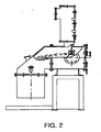
- a cylindrical rod having a diameter of 12 mm is provided at an induction coil as a melting unit and is melted at an end thereof using an apparatus of FIG. 2 according to the present invention.
- the molten portion of the rod comes into contact with a disk, which rotates at a high speed of 1 - 100 m/sec, to instantaneously produce metal fibers having a diameter of 20 - 70 ⁇ m.
- the metal fibers each have a crescent section as shown in FIG. 1b , and a plurality of protrusions which protrude by a height of 1 - 5 ⁇ m from a longitudinal surface thereof as shown in FIG.
- Each metal fiber, which is produced through the melt extraction method, has protrusions having heights of micron units, thus falling-out of the metal fiber is prevented in the course of producing the yarn. Accordingly, it is possible to easily produce the yarn using the metal fibers of the present invention in comparison with metal fibers produced through a conventional machining process.
- a cutting method and a drawing method are employed to produce a fine metal fiber through the machining process.
- a metal sheet is wound like a coil as shown in FIG. 3 , and a section of the wound metal sheet is cut to produce metal fibers.
- the drawing method after a plurality of surface-treated wires is firstly drawn, the firstly drawn wires are collected in a protection pipe 1 as shown in FIG. 4a , and secondly drawn as shown in FIG. 4b . The drawing is repeated a predetermine number of times, and the protection pipe is melted to produce metal fibers as shown in FIG. 4c .
- machining processes are different from the melt extraction method in that metal is repeatedly mechanically processed at a temperature that is lower than a melting point thereof to produce the fine fiber and each metal fiber manufactured by the.machining process has a smooth surface without the protrusions as shown in FIG. 5 .
- Improved Fecralloy ® which contains an iron-chromium-aluminum-based alloy as a main component, and 0.05 -0.5 wt%, preferably 0.1 - 0.3 wt%, Zr is used to produce the metal fibers of the present invention.
- a fabric which includes Fecralloy ® containing Zr in the above amount, is used as a membrane, an oxidation life is excellent.
- Typical Fecralloy ® is used in the present invention, and it comprises, for example, 70 - 83 wt% iron (Fe), 18 - 27 wt% chromium (Cr) , 3 - 7 wt% aluminum (Al) , and 0.05 -0.5 wt% zirconium (Zr).
- the metal fiber yarn according to the present invention is produced using randomly oriented metal fibers which are produced using Fecralloy ® through the melt extraction method.
- the fine metal fibers produced through the melt extraction method are randomly distributed with each other as shown in FIG. 1a , and it is necessary to orient the fibers to produce the yarn.
- the randomly oriented mental fibers may be continuously combed many times in order to arrange the metal fibers parallel to one another. The orientation is repeated until the one yarn consists of about 50 - 100.
- metal fibers When the number of fibers is less than 50, they become tangled because the number of fibers constituting the one yarn is small, thus it is difficult to desirably produce the yarn. When the number of fibers is more than 100, breathability is reduced and an intensity change range is narrow during combustion, thus gas is undesirably discharged. With respect to this, the metal fiber has a diameter of 20 - 70 ⁇ m and a length of 10 - 20 cm.
- the yarn is produced so as to have a' length of 0.45-0.6m/g (0.45-0.6 Nm) and a torsion ratio of 1 - 9 turns/m. If the length per gram is less than 0.45, the yarn is thick, and thus, undesirably, porosity is reduced. If the length per gram is more than 0.6, the yarn is thin, thus it is difficult to maintain the thickness of the yarn.
- the yarn when the yarn is used as a membrane for a burner, the yarn has a predetermined torsion ratio so that the metal fibers do not fall out from the yarn while gas fuel is easily discharged between the metal fibers.
- the torsion ratio is more than 9 turns/m the metal fibers are densely arranged in the metal fiber yarn due to a characteristic of the metal fibers produced through the melt extraction method, thus it is difficult to conduct the discharge of the fuel gas. If the torsion ratio is less than 1, turn/m, the metal fibers easily fall out of the yarn, thus it is difficult to desirably produce the yarn.
- the metal fiber yarn of the present invention is produce by means of a twisting operation and has the torsion ratio of 1 - 9 turns/m. Hence, the metal fibers are not removed from the yarn and the shape of the yarn is maintained, thus it is easy to produce a fabric using the yarn. Furthermore, in order to reinforce the maintenance of the shape of the yarn, the yarn can further comprise polymer or natural fibers, which are disposed in nearly parallel arrangement in the yarn.
- the polymer fibers may be polyamide fibers, polyester fibers, polyethylene fibers, polypropylene fibers, acrylic fibers and polyvinylalcohol polymers, etc. and natural fibers may be cotton or wool.
- the weight of polymer or natural fibers in the yarn is less than 15% by weight of the yarn, preferably even less than 10% by weight.
- the polymer or natural fibers can be removed easily by burning or any other appropriate means.
- the yarn in which the metal fibers produced through the melt extraction method are combed, is processed to form a fabric having a density of 1.0 - 4.0 kg/m 2 , and the fabric thus formed is used as the membrane for the porous surface combustion burner.
- the density of the fabric is less than 1.0 kg/m 2 since the fabric, in which the yarns having a predetermined thickness are arranged at a wide interval, is produced, discharge of fuel gas is large, thus combustion is insufficiently achieved. If the density is more than 4.0 kg/m 2 , since the interval between the yarns is too narrow, discharge of fuel gas is low, and thus, undesirably, combustion is scarcely achieved.
- the fabric produced so as to have a density of 1.0 - 4.0 kg/m 2 is 0.5 - 2.5 mm thick.
- the fibers produced through the melt extraction method of the present invention are oriented unidirectiionally and twisted to produce the yarn, the fibers do not fall out from the yarn, thus the shape of the yarn is stably maintained. Furthermore, the fabric is produced so that the interval between the yarns is constant, and it is possible to use the fabric as the membrane for the burner having excellent combustion efficiency, combustion range, and porosity.
- fabric used in the present invention is intended to include any fabric produced by weaving or knitting the yarns of the present invention.
- weft and warp are arranged perpendicular to each other, and flame holes, which each have two parallel warps and two parallel wefts as sides thereof, are formed on both sides of the fabric.
- the flame holes correspond to sparing recesses on the lower and upper sides of the fabric.
- the flame holes are formed in the shape of a slit in which a ratio of length to width is 10:1 or less, and preferably, 1:1 - 10:1. If the ratio of length to width is more than 10, since the flame holes must be formed using 3 - 4 lower yarns, undesirably, the fabric is slack. If the slit, in which the ratio of length to width is 10:1 or less, has desirable porosity, it is possible for the fabric including the slit to have any ratio of length to width.
- the fine pores between the fibers act as fine slit-type flame holes, thus a wide combustion characteristic ranging from a high intensity region to a low intensity region is realized.
- porosity is 70 - 95 %.
- the metal fiber is produced through the melt extraction method using Fecralloy ® containing Fe, Cr, Al, and Zr components, and randomly oriented as shown in FIG. 1a .
- a diameter and a length of the fiber are 20 - 70 ⁇ m and 10 - 20 cm, respectively, and a section and a longitudinal surface of the metal fiber are shown in FIGS. 1b and 1c , respectively.
- the metal fiber produced through the melt extraction method has a crescent section as shown in the picture of FIG. 1b , and the longitudinal surface, on which a plurality of protrusions are formed in a height of 1 - 5 ⁇ m, as shown in the picture of FIG. 1c .
- FIG. 5 longitudinal surfaces of metal fibers, which are produced through a machining process, are shown in FIG. 5 .
- the longitudinal surfaces of the metal fibers produced through the machining process are smooth without protrusions as shown in the picture of FIG. 5 .
- Transverse sections of metal fibers, which are produced through a cutting method belonging to the machining process are shown in FIG. 6 .
- FIG. 7 a transverse section of a protection pipe 1 including a plurality of metal fibers of FIG. 4b is shown in FIG. 7 .
- FIG. 7 when the metal fibers are produced through the drawing method, the metal fibers are surrounded by a plurality of protection pipes, which is shown in the form of dark boundary lines at the center of FIG. 7 .
- FIG. 8 illustrates the metal fiber yarn according to the present invention.
- the metal fibers 2 are continuously combed many times to be unidirectionally oriented, and 50 - 100 plies of metal fibers 2 are formed into one ply of yarn, thereby preparing the metal fiber yarn.
- the metal fiber yarn has a length of 0.45 - 0.6 m/g and a torsion ratio of 1 - 9 turns/m.
- the metal fibers 2 have not fallen out from the yarn and the shape of the yarn is maintained, thus the production of the fabric is easy.
- the fabric thus produced is used as a membrane for a combustion burner, the flow rate of gas in fine gaps between the metal fibers 2 increases even though a small amount of fuel is supplied, thus gas easily sprouts from the yarn and stable combustion is achieved.
- the metal fiber yarn of FIG. 8 is woven or knitted to produce the fabric, and the fabric thus produced is used as the porous membrane for the surface combustion burner.
- a picture of a fabric, which is produced through a weaving process according to the present invention is shown in FIG. 9
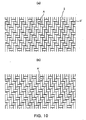
- lower and upper sides of the woven fabric (membrane) are shown in FIGS. 10a and 10b , respectively
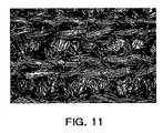
- a picture of a fabric, which is produced through a knitting process is shown in FIG. 11 .
- Lower and upper sides of the fabric have the same shape. For convenience of understanding, however, the side of the fabric that directly comes into contact with fuel gas is considered as the lower side ( FIG. 10a ), and the opposite side of the fabric is considered as the upper side ( FIG. 10b ).
- the fabric of the present invention which is produced through the weaving process, is produced by weaving the metal fiber yarns as warp 3 and weft 3' so that the warp and the weft are arranged perpendicular to each other. Furthermore, the woven fabric has a density of 1.0 - 4.0 kg/m 2 and a thickness of 0.5 - 2.5 mm.
- flame holes (A, A'), which each have two parallel warps and the two parallel wefts as sides thereof, are formed in the shape of a slit in which a ratio of length to width is 10:1 or less.
- a cylindrical rod having a diameter of 12 mm was provided at an induction coil as a melting unit, heated to 1600°C, and was melted at an end thereof using an apparatus of FIG. 2 according to the method of U.S. Pat. No. 6,604,570 .
- the molten portion of the rod came into contact with a disk, which rotated at a high circumferential speed of 20 m/sec, to instantaneously produce metal fibers having a diameter of 50 ⁇ m.
- the metal fibers were randomly arranged, and each had a crescent section and a length of about 10 - 18 cm.
- Components of each metal fiber were 22 wt% chromium, 5.5 wt% aluminum, 0.3 wt% zirconium, and the balance of iron (Fe).
- the randomly distributed metal fibers were continuously combed 100 times to be unidirectionally oriented to produce a metal fiber yarn consisting of 80 plies of metal fibers.
- the yarn thus produced had a length of 0.55 m/g and a torsion ratio of about 8 turns/m.
- the yarn which was produced using the metal fibers produced through the melt extraction method as Example 1, was woven to produce a fabric having a density of 1.5 kg/m 2 and a thickness of 1.5 mm as shown in FIG. 9 .
- flame holes were formed on both sides of the fabric in the shape of a slit in which a ratio of length to width was 5:1.
- the fabric included 14 yarns per inch (5.5 yarns/cm), which each consisted of 80 plies of metal fibers, and porosity of the fabric was 85 %.
- the calorific value of 200 - 2,000 kW/m 2 was assured using burners of 20,000 and 50,000 kcal/h. Therefore, it was possible to produce a combustion membrane having the wide combustion intensity range, in which the ratio of minimum calorific value to maximum calorific value was 1:10.
- a heat capacity (kcal/h) and an intensity capacity (kW/m 2 ) of the burner were easily controlled using parts constituting the burner.
- Metal fibers were produced through a cutting method disclosed in U.S. Pat. No. 4,930,199 .
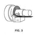
- a metal sheet which consisted of 22 wt% chromium, 5.5 wt% aluminum, 0.3 wt% zirconium, and the balance of iron (Fe), and had a thickness of 0.1 mm, was wound around a rotatable shaft like a cylinder as shown in FIG. 3 .
- the metal sheet was cut using a cutter, which moved at a speed of 0.10 mm/min and had a width of 20 mm, at a cutting speed of 72 m/min so that a face angle ( ) between the cutter and the shaft was 32 degree, thereby creating the metal fibers, which each had a rectangular shape having a length of 50 ⁇ m and a width of 20 ⁇ m.
- the metal fibers which were produced through the cutting method disclosed in the above U.S. Pat. No. 4,930,199 , included fibers having a length of 20 cm or more, and longitudinal surfaces of the fibers were smooth. Accordingly, it was impossible to produce yarn having a low torsion ratio according to the present invention.
- the metal fibers produced through the melt extraction method were used to produce the yarn, the metal fibers did not fall out from the yarn due to the plurality of protrusions formed on the longitudinal surfaces of the metal fibers.
- the metal fibers produced through a machining process the metal fibers easily fall out of the yarn because the surfaces of the fibers were smooth, thus the shape of the yarn was not maintained.
- the yarns produced according to the present invention may be woven or knitted to produce a fabric.
- fuel uniformly flows from a lower side of the membrane to an upper side of the membrane due to pores formed on lower and upper sides of the fabric, and fine pores between the metal fiber yarns having unidirectional orientation and a predetermined torsion ratio. Accordingly, it is possible to produce a combustion membrane having a wide combustion range in which the ratio of the minimum calorific value to the maximum calorific value is 1:10. Additionally, the membrane of the present invention has excellent combustion efficiency and porosity.
Landscapes
- Engineering & Computer Science (AREA)
- Mechanical Engineering (AREA)
- Textile Engineering (AREA)
- Chemical & Material Sciences (AREA)
- Inorganic Chemistry (AREA)
- Combustion & Propulsion (AREA)
- General Engineering & Computer Science (AREA)
- Woven Fabrics (AREA)
- Yarns And Mechanical Finishing Of Yarns Or Ropes (AREA)
Abstract
Description
- The present invention relates to a metal fiber yarn, a fabric comprising the metal fiber yarn, a method for manufacturing the fabric, and a membrane for a surface combustion burner using the fabric. More particularly, the present invention pertains to a metal fiber yarn, which can be used for manufacturing a membrane for a surface combustion burner having a wide combustion range and high porosity, a fabric comprising the metal fiber yarn, a method for manufacturing the fabric, and the use of the fabric as a membrane for the surface combustion burner.
- Generally, a surface combustion burner is produced using a porous metal fiber membrane (media), and mixture gas of fuel and air is combusted on the surface of the porous metal fiber membrane. The membrane for the surface combustion burner is heated at a high temperature of 1000°C or more, thus it is produced using a heat-resistant metal or ceramic fiber.
- With respect to a conventional technology, which relates to a metal fiber used for a porous gas burner membrane and to the membrane produced using the metal fiber,
US 2003/138629 discloses a method of producing a gas burner membrane using yarns comprising metal fibers, and a fabric comprising the yarns. The machined metal fiber bundle is surrounded by polymers or natural fibers, and is consolidated with each other using a binding agent. After the fabric is produced using the metal fiber yarn, the binding agent and the polymers or the natural fibers are removed from the fabric. The method of producing the yarns by surrounding the metal fibers using the binding agent and the polymers or the natural fibers as disclosed in the above PCT patent is frequently employed to produce a yarn using metal fibers produced through a machining process. As known in the art, the metal fibers, which are mechanically processed using devices shown inFIGS. 3 to 4 , have a predetermined orientation after the machining is finished, and are a bundle of the metal fibers having a desired diameter due to a fine drafting process. -
US 7,053,014 discloses a burner membrane produced using a fabric which contains at least 60 wt% of machined metal fiber bundle having a bundle voluminousity in the range of 1 - 15 % and a torsion ratio of 10 - 80 turns/m. - Furthermore,
US 6,025,282 discloses a fabric and a membrane for a gas burner produced using the fabric. In the patent, metal filaments, which are produced through a machining process such asUSP No. 4,930,199 and have an equivalent filament diameter of 15 - 150 µm, are parallelly combined with each other without a twisting operation using a binding agent to form bundles of filaments, and the bundles of filaments are woven or knitted to produce the fabric. - However, the above PCT patent is problematic in that, since metal fibers, which are produced through a machining process according to
U.S. Pat. Nos. 4,930,199 and5,071,713 , are unidirectionally oriented and the bundle of metal fibers includes the predetermined number of metal fibers, it is difficult to produce a porous membrane for a combustion burner when lengths of the fibers are short or fiber distribution is unparallel or nonuniform. - Therefore, the present inventors have conducted extensive studies into production of a metal fiber yarn having a unidirectional orientation from metal fibers, which have a nonuniform distribution or are randomly oriented, thereby accomplishing the present invention.
- An object of the present invention is to provide a metal fiber yarn having a unidirectional orientation, which is used as a membrane for a surface combustion burner having high porosity and a wide combustion range, and is produced using randomly oriented metal fibers manufactured by a melt extraction method.
- Another object of the present invention is .to provide a fabric produced using the metal fiber yarn.
- A further object of the present invention is to provide a method for manufacturing the fabric using the metal fiber yarn.
- Yet another object of the present invention is to provide the membrane for the surface combustion burner having uniform combustion efficiency and high porosity.
- According to an aspect of the present invention, there is provided a metal fiber yarn having a length of 0.45 -0.6 m/g and a torsion ratio of 1 - 9 turns/m. The metal fiber yarn comprises 50 - 100 unidirectionally oriented metal fibers, which are prepared by combing randomly oriented metal fibers as shown in
Fig. 1(a) , manufactured by an apparatus used in a melt extraction method as shown inFIG. 2 . Each of the metal fibres has a crescent section, a length of 10 - 20 cm and a protrusion that protrudes by a height of 1 - 5 µm from a surface thereof. - According to another aspect of the present invention, there is provided a fabric produced using the metal fiber yarn.
- According to a further aspect of the present invention, there is provided a method for manufacturing the fabric. The method comprises combing randomly oriented metal fibers, which are produced through a melt extraction method, to prepare unidirectionally oriented metal fibers; producing a metal fiber yarn, and producing the fabric using the metal fiber yarn. The metal fiber yarn consists of 50 - 100 unidirectionally oriented metal fibers and has a length of 0.45 - 0.6 m/g and a torsion ratio of 1 - 9 turns/m and each of the metal fibres has a crescent section, a length of 10 - 20 cm and a protrusion that protrudes by a height of 1 - 5 µm from a surface thereof.
- According to still another aspect of the present invention, there is provided a surface combustion burner membrane having high porosity and high combustion efficiency, which is produced using the fabric.
- The above and other objects, features and other advantages of the present invention will be more clearly understood from the following detailed description taken in conjunction with the accompanying drawings, in which:
-
FIG. 1a is a picture showing randomly oriented metal fibers produced through a melt extraction method,FIG. 1b is a SEM (Scanning Electron Microscope) picture (200 X magnification) showing transverse sections, of the metal fibers produced through the melt extraction method, andFIG. 1c is a SEM picture (600 X magnification) showing the longitudinal surface of one metal fiber produced through the melt extraction method; -
FIG. 2 schematically illustrates an apparatus used in the melt extraction method; -
FIG. 3 schematically illustrates a device used in a cutting method belonging to a conventional machining process; -
FIGS. 4a to 4c schematically illustrates a drawing method belonging to the conventional machining process; -
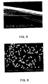
FIG. 5 is a SEM picture (500 X magnification) showing longitudinal surfaces of metal fibers produced through the conventional machining method; -
FIG. 6 is a SEM picture (50 X magnification) showing transverse sections of metal fibers produced through the conventional cutting method; -
FIG. 7 is a SEM picture (1000 X magnification) showing transverse sections of metal fibers produced through the conventional drawing method; -
FIG. 8 illustrates a metal fiber yarn according to the present invention; -
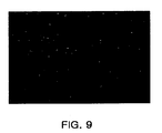
FIG. 9 is a picture of a fabric produced by weaving the metal fiber yarns according to the present invention; -
FIGS. 10a and 10b illustrate lower and upper sides, respectively, of a fabric in which slit-type flame holes are formed, according to the present invention; -
FIG. 11 is a picture of a fabric produced by knitting metal fiber yarns according to the present invention; -
FIG. 12 illustrates pictures of flames having a calorific value of 418 KW/m2 during combustion using a membrane for a combustion burner according to the present invention; and -
FIG. 13 illustrates pictures of flames having a calorific value of 1063 KW/m2 during combustion using the membrane for the combustion burner according to the present invention. - Hereinafter, a detailed description will be given of the present invention.
- A metal fiber yarn according to the present invention comprises metal fibers which are produced through a melt extraction method and have a crescent section, a diameter of 20 - 70 µm and a length of 10 - 20 cm. When the diameter is less than 20 µm, undesirably, the fibers are easily broken while they are combed. When the diameter is more than 70 µm, it is impossible to desirably produce the yarn because the number of the fibers constituting the yarn is small. When the length of the fiber is less than 10 cm, undesirably, it is difficult to produce the yarn because of the short length. It is difficult to produce a metal fiber that is longer than 20 cm and the diameter is 20 - 70 µm, through the melt extraction method.
- In the melt extraction method as described in
U.S. Pat. No. 6,604,570 , which has been made by the applicant of the present invention, a cylindrical rod having a diameter of 12 mm is provided at an induction coil as a melting unit and is melted at an end thereof using an apparatus ofFIG. 2 according to the present invention. The molten portion of the rod comes into contact with a disk, which rotates at a high speed of 1 - 100 m/sec, to instantaneously produce metal fibers having a diameter of 20 - 70 µm. The metal fibers each have a crescent section as shown inFIG. 1b , and a plurality of protrusions which protrude by a height of 1 - 5 µm from a longitudinal surface thereof as shown inFIG. 1c . Each metal fiber, which is produced through the melt extraction method, has protrusions having heights of micron units, thus falling-out of the metal fiber is prevented in the course of producing the yarn. Accordingly, it is possible to easily produce the yarn using the metal fibers of the present invention in comparison with metal fibers produced through a conventional machining process. - Typically, a cutting method and a drawing method are employed to produce a fine metal fiber through the machining process. In the cutting method, a metal sheet is wound like a coil as shown in
FIG. 3 , and a section of the wound metal sheet is cut to produce metal fibers. In the drawing method, after a plurality of surface-treated wires is firstly drawn, the firstly drawn wires are collected in a protection pipe 1 as shown inFIG. 4a , and secondly drawn as shown inFIG. 4b . The drawing is repeated a predetermine number of times, and the protection pipe is melted to produce metal fibers as shown inFIG. 4c . However, these machining processes are different from the melt extraction method in that metal is repeatedly mechanically processed at a temperature that is lower than a melting point thereof to produce the fine fiber and each metal fiber manufactured by the.machining process has a smooth surface without the protrusions as shown inFIG. 5 . - Improved Fecralloy®, which contains an iron-chromium-aluminum-based alloy as a main component, and 0.05 -0.5 wt%, preferably 0.1 - 0.3 wt%, Zr is used to produce the metal fibers of the present invention. When a fabric, which includes Fecralloy® containing Zr in the above amount, is used as a membrane, an oxidation life is excellent. Typical Fecralloy® is used in the present invention, and it comprises, for example, 70 - 83 wt% iron (Fe), 18 - 27 wt% chromium (Cr) , 3 - 7 wt% aluminum (Al) , and 0.05 -0.5 wt% zirconium (Zr).
- The metal fiber yarn according to the present invention is produced using randomly oriented metal fibers which are produced using Fecralloy® through the melt extraction method.
- The fine metal fibers produced through the melt extraction method are randomly distributed with each other as shown in
FIG. 1a , and it is necessary to orient the fibers to produce the yarn. The randomly oriented mental fibers may be continuously combed many times in order to arrange the metal fibers parallel to one another. The orientation is repeated until the one yarn consists of about 50 - 100. metal fibers. When the number of fibers is less than 50, they become tangled because the number of fibers constituting the one yarn is small, thus it is difficult to desirably produce the yarn. When the number of fibers is more than 100, breathability is reduced and an intensity change range is narrow during combustion, thus gas is undesirably discharged. With respect to this, the metal fiber has a diameter of 20 - 70 µm and a length of 10 - 20 cm. - Furthermore, the yarn is produced so as to have a' length of 0.45-0.6m/g (0.45-0.6 Nm) and a torsion ratio of 1 - 9 turns/m. If the length per gram is less than 0.45, the yarn is thick, and thus, undesirably, porosity is reduced. If the length per gram is more than 0.6, the yarn is thin, thus it is difficult to maintain the thickness of the yarn.
- Additionally, when the yarn is used as a membrane for a burner, the yarn has a predetermined torsion ratio so that the metal fibers do not fall out from the yarn while gas fuel is easily discharged between the metal fibers. In other words, if the torsion ratio is more than 9 turns/m the metal fibers are densely arranged in the metal fiber yarn due to a characteristic of the metal fibers produced through the melt extraction method, thus it is difficult to conduct the discharge of the fuel gas. If the torsion ratio is less than 1, turn/m, the metal fibers easily fall out of the yarn, thus it is difficult to desirably produce the yarn.
- The metal fiber yarn of the present invention is produce by means of a twisting operation and has the torsion ratio of 1 - 9 turns/m. Hence, the metal fibers are not removed from the yarn and the shape of the yarn is maintained, thus it is easy to produce a fabric using the yarn. Furthermore, in order to reinforce the maintenance of the shape of the yarn, the yarn can further comprise polymer or natural fibers, which are disposed in nearly parallel arrangement in the yarn. The polymer fibers may be polyamide fibers, polyester fibers, polyethylene fibers, polypropylene fibers, acrylic fibers and polyvinylalcohol polymers, etc. and natural fibers may be cotton or wool. The weight of polymer or natural fibers in the yarn is less than 15% by weight of the yarn, preferably even less than 10% by weight. The polymer or natural fibers can be removed easily by burning or any other appropriate means.
- As well, since fuel gas is easily discharged between the fibers, it is possible to produce the fabric for a surface combustion burner membrane having high porosity and excellent combustion efficiency.
- The yarn, in which the metal fibers produced through the melt extraction method are combed, is processed to form a fabric having a density of 1.0 - 4.0 kg/m2, and the fabric thus formed is used as the membrane for the porous surface combustion burner.
- If the density of the fabric is less than 1.0 kg/m 2 since the fabric, in which the yarns having a predetermined thickness are arranged at a wide interval, is produced, discharge of fuel gas is large, thus combustion is insufficiently achieved. If the density is more than 4.0 kg/m2, since the interval between the yarns is too narrow, discharge of fuel gas is low, and thus, undesirably, combustion is scarcely achieved. The fabric produced so as to have a density of 1.0 - 4.0 kg/m2 is 0.5 - 2.5 mm thick.
- Since the fibers produced through the melt extraction method of the present invention are oriented unidirectiionally and twisted to produce the yarn, the fibers do not fall out from the yarn, thus the shape of the yarn is stably maintained. Furthermore, the fabric is produced so that the interval between the yarns is constant, and it is possible to use the fabric as the membrane for the burner having excellent combustion efficiency, combustion range, and porosity.
- It should be understood that the term "fabric" used in the present invention is intended to include any fabric produced by weaving or knitting the yarns of the present invention.
- Furthermore, according to the present invention, in the fabric, weft and warp are arranged perpendicular to each other, and flame holes, which each have two parallel warps and two parallel wefts as sides thereof, are formed on both sides of the fabric.
- The flame holes correspond to sparing recesses on the lower and upper sides of the fabric. The flame holes are formed in the shape of a slit in which a ratio of length to width is 10:1 or less, and preferably, 1:1 - 10:1. If the ratio of length to width is more than 10, since the flame holes must be formed using 3 - 4 lower yarns, undesirably, the fabric is slack. If the slit, in which the ratio of length to width is 10:1 or less, has desirable porosity, it is possible for the fabric including the slit to have any ratio of length to width.
- When the fabric of the present invention is used as the membrane for the surface combustion burner, fuel flows through the slit-type flame holes, which are formed by the yarn of the lower side of the membrane, and through fine pores of the fabric into the upper side of the membrane, and combusted at the slit-type flame holes of the upper side. Accordingly, mixture gas is further uniformly distributed. In other words, fuel gas, which is fed to the lower side of the membrane, is divided by the yarns of the lower side of the membrane, and flows through the slit-type flame holes, the fine pores of the fabric, and fine pores between the metal fibers constituting the yarn to the yarn of the upper side of the membrane. At this time, gas spouts through the pores of the membrane and the yarn and through the slit-type flame holes of the upper side of the membrane, and is combusted, thus fuel is uniformly discharged and combusted.
- Particularly, since fuel gas spouts little by little through the pores formed between the metal fibers, the flow rate of gas between the metal fibers increases even though a small amount of fuel is fed, thus the combustion is stably achieved. In other words, the fine pores between the fibers act as fine slit-type flame holes, thus a wide combustion characteristic ranging from a high intensity region to a low intensity region is realized. When the density of the fabric is 1.0 - 4.0 kg/m2, porosity is 70 - 95 %.
- Hereinafter, a detailed description will be given of the present invention, with reference to the accompanying drawings.
- Used as a raw material in the present invention, the metal fiber is produced through the melt extraction method using Fecralloy® containing Fe, Cr, Al, and Zr components, and randomly oriented as shown in
FIG. 1a . A diameter and a length of the fiber are 20 - 70 µm and 10 - 20 cm, respectively, and a section and a longitudinal surface of the metal fiber are shown inFIGS. 1b and 1c , respectively. The metal fiber produced through the melt extraction method has a crescent section as shown in the picture ofFIG. 1b , and the longitudinal surface, on which a plurality of protrusions are formed in a height of 1 - 5 µm, as shown in the picture ofFIG. 1c . - Meanwhile, longitudinal surfaces of metal fibers, which are produced through a machining process, are shown in
FIG. 5 . The longitudinal surfaces of the metal fibers produced through the machining process are smooth without protrusions as shown in the picture ofFIG. 5 . Transverse sections of metal fibers, which are produced through a cutting method belonging to the machining process, are shown inFIG. 6 . Additionally, during the production of metal fibers through a drawing method, a transverse section of a protection pipe 1 including a plurality of metal fibers ofFIG. 4b is shown inFIG. 7 . In other words, as shown inFIG. 7 , when the metal fibers are produced through the drawing method, the metal fibers are surrounded by a plurality of protection pipes, which is shown in the form of dark boundary lines at the center ofFIG. 7 . - In the metal fibers produced through the melt extraction method of the present invention, removal of the metal fibers from the metal fiber yarn is prevented due to a plurality of protrusions formed on surfaces of the metal fibers as shown in a picture of
FIG. 1c , thus it is possible to easily produce the yarn without using a separate binding agent and/or surrounding or enveloped polymer. -
FIG. 8 illustrates the metal fiber yarn according to the present invention. In order to produce the metal fiber yarn of the present invention, themetal fibers 2 are continuously combed many times to be unidirectionally oriented, and 50 - 100 plies ofmetal fibers 2 are formed into one ply of yarn, thereby preparing the metal fiber yarn. The metal fiber yarn has a length of 0.45 - 0.6 m/g and a torsion ratio of 1 - 9 turns/m. In the metal fiber yarn (FIG. 8 ) of the present invention having the above torsion ratio range, themetal fibers 2 have not fallen out from the yarn and the shape of the yarn is maintained, thus the production of the fabric is easy. When the fabric thus produced is used as a membrane for a combustion burner, the flow rate of gas in fine gaps between themetal fibers 2 increases even though a small amount of fuel is supplied, thus gas easily sprouts from the yarn and stable combustion is achieved. - The metal fiber yarn of
FIG. 8 is woven or knitted to produce the fabric, and the fabric thus produced is used as the porous membrane for the surface combustion burner. Particularly, a picture of a fabric, which is produced through a weaving process according to the present invention, is shown inFIG. 9 , lower and upper sides of the woven fabric (membrane) are shown inFIGS. 10a and 10b , respectively, and a picture of a fabric, which is produced through a knitting process, is shown inFIG. 11 . Lower and upper sides of the fabric have the same shape. For convenience of understanding, however, the side of the fabric that directly comes into contact with fuel gas is considered as the lower side (FIG. 10a ), and the opposite side of the fabric is considered as the upper side (FIG. 10b ). - As shown in
FIGS. 10a and 10b , the fabric of the present invention, which is produced through the weaving process, is produced by weaving the metal fiber yarns as warp 3 and weft 3' so that the warp and the weft are arranged perpendicular to each other. Furthermore, the woven fabric has a density of 1.0 - 4.0 kg/m2 and a thickness of 0.5 - 2.5 mm. - During the weaving process, flame holes (A, A'), which each have two parallel warps and the two parallel wefts as sides thereof, are formed in the shape of a slit in which a ratio of length to width is 10:1 or less.
- A better understanding of the present invention may be obtained through the following examples and a comparative example which are set forth to illustrate, but are not to be construed as the limit of the present invention.
- A cylindrical rod having a diameter of 12 mm was provided at an induction coil as a melting unit, heated to 1600°C, and was melted at an end thereof using an apparatus of
FIG. 2 according to the method ofU.S. Pat. No. 6,604,570 . The molten portion of the rod came into contact with a disk, which rotated at a high circumferential speed of 20 m/sec, to instantaneously produce metal fibers having a diameter of 50 µm. The metal fibers were randomly arranged, and each had a crescent section and a length of about 10 - 18 cm. Components of each metal fiber were 22 wt% chromium, 5.5 wt% aluminum, 0.3 wt% zirconium, and the balance of iron (Fe). - The randomly distributed metal fibers were continuously combed 100 times to be unidirectionally oriented to produce a metal fiber yarn consisting of 80 plies of metal fibers. The yarn thus produced had a length of 0.55 m/g and a torsion ratio of about 8 turns/m.
- The yarn, which was produced using the metal fibers produced through the melt extraction method as Example 1, was woven to produce a fabric having a density of 1.5 kg/m2 and a thickness of 1.5 mm as shown in
FIG. 9 . As shown inFIGS. 10a and 10b , flame holes were formed on both sides of the fabric in the shape of a slit in which a ratio of length to width was 5:1. Furthermore, the fabric included 14 yarns per inch (5.5 yarns/cm), which each consisted of 80 plies of metal fibers, and porosity of the fabric was 85 %. - Mixture gas, in which fuel gas was mixed with air in a variable mixing ratio of the following λ, was fed into the fabric, and combustion was conducted. When the combustion was carried out so that the ratio of air to fuel gas (λ: air/fuel gas) was 1.05, 1.25, and 1.42, a calorific value was 418 kW/m2. Furthermore, when combustion was implemented so that the ratio of air to fuel gas (λ) was 1.03, 1.22, 1.41, and 1.69, the calorific value was 1,063 kW/m 2 Pictures of flames, which changed according to changes in the ratio of air to fuel gas during combustion, are shown in
FIGS. 12 and13 . When the fabric of the present invention was used as a membrane for a surface combustion burner, a wide combustion intensity range, at which the ratio of minimum combustion intensity to maximum combustion intensity was 1:2.5, was assured, and it was possible to realize both radiation and transition modes. - For example, when the combustion membrane of the present invention was subjected to combustion characteristic analysis, the calorific value of 200 - 2,000 kW/m2 was assured using burners of 20,000 and 50,000 kcal/h. Therefore, it was possible to produce a combustion membrane having the wide combustion intensity range, in which the ratio of minimum calorific value to maximum calorific value was 1:10. A heat capacity (kcal/h) and an intensity capacity (kW/m2) of the burner were easily controlled using parts constituting the burner.
- Metal fibers were produced through a cutting method disclosed in
U.S. Pat. No. 4,930,199 . A metal sheet, which consisted of 22 wt% chromium, 5.5 wt% aluminum, 0.3 wt% zirconium, and the balance of iron (Fe), and had a thickness of 0.1 mm, was wound around a rotatable shaft like a cylinder as shown inFIG. 3 . The metal sheet was cut using a cutter, which moved at a speed of 0.10 mm/min and had a width of 20 mm, at a cutting speed of 72 m/min so that a face angle () between the cutter and the shaft was 32 degree, thereby creating the metal fibers, which each had a rectangular shape having a length of 50 µm and a width of 20 µm. However, the metal fibers, which were produced through the cutting method disclosed in the above
U.S. Pat. No. 4,930,199 , included fibers having a length of 20 cm or more, and longitudinal surfaces of the fibers were smooth. Accordingly, it was impossible to produce yarn having a low torsion ratio according to the present invention. - When the metal fibers produced through the melt extraction method were used to produce the yarn, the metal fibers did not fall out from the yarn due to the plurality of protrusions formed on the longitudinal surfaces of the metal fibers. On the other hand, when using the metal fibers produced through a machining process, the metal fibers easily fall out of the yarn because the surfaces of the fibers were smooth, thus the shape of the yarn was not maintained.
- Since a plurality of protrusions are formed on surfaces of randomly oriented metal fibers, which are produced through a melt extraction method, falling out of the metal fibers from a metal fiber yarn is prevented, thus it is possible to easily produce the yarn. Furthermore, the yarns produced according to the present invention may be woven or knitted to produce a fabric. Particularly, when the yarn is used as a membrane for a burner, fuel uniformly flows from a lower side of the membrane to an upper side of the membrane due to pores formed on lower and upper sides of the fabric, and fine pores between the metal fiber yarns having unidirectional orientation and a predetermined torsion ratio. Accordingly, it is possible to produce a combustion membrane having a wide combustion range in which the ratio of the minimum calorific value to the maximum calorific value is 1:10. Additionally, the membrane of the present invention has excellent combustion efficiency and porosity.
Claims (17)
- A metal fiber yarn comprising 50 - 100 unidirectionally oriented metal fibers, wherein said unidirectionally oriented metal fibers are prepared by combing randomly oriented metal fibers manufactured by a melt extraction method, characterised in that each of the metal fibers has a crescent section, a length of 10 - 20 cm and a protrusion that protrudes by a height of 1 - 5 µm from a surface thereof; and said metal fiber yarn has a length of 0.45 -0.6 m/g and a torsion ratio of 1 - 9 turns/m.
- The metal fiber yarn as set forth in claim 1, wherein the metal fibers are made of an iron-chromium-aluminum-based alloy containing 0.05 - 0.5 wt% zirconium.
- The metal fiber yarn as set forth in claim 2, wherein the metal fibers are made of an iron-chromium-aluminum-based alloy containing 0.1 -0.3 wt% zirconium.
- The metal fiber yarn as set forth in claim 2, wherein the metal fibers are made of an iron-chromium-aluminum-based alloy containing 70 - 83 wt% iron, 18 - 27 wt% chromium, 3 - 7 wt% aluminum, and 0.05 0.5 wt% zirconium.
- The metal fiber yarn as set forth in claim 1, wherein a cylindrical rod having a diameter of 12 mm is provided at an induction coil of a melting unit and melted at an end thereof, and a molten portion of the cylindrical rod comes into contact with a disk, which rotates at a high speed of 1 - 100 m/sec, to instantaneously produce the metal fibers having a crescent section in the melt extraction method.
- The metal fiber yarn as set forth in claim 1, wherein the metal fiber yarn further comprises polymer or natural fibers, which are disposed in nearly parallel arrangement in the yarn.
- A fabric comprising the metal fiber yarn according to any one of claims 1 to 6.
- The fabric as set forth in claim 7, wherein the fabric has a density of 1.0 - 4.0 kg/m2.
- The fabric as set forth in claim 7, wherein the fabric is a woven fabric or a knitted fabric.
- The fabric as set forth in claim 7, wherein the fabric has porosity of 75 - 95 %.
- The fabric as set forth in claim 7, wherein flame holes are formed in a slit shape, a ratio of length to width of which is 10:1 or less, on lower and upper sides of the fabric.
- A method for manufacturing a fabric, comprising:combing randomly oriented metal fibers, which are produced through a melt extraction method, to prepare unidirectionally oriented metal fibers;producing a metal fiber yarn, which consists of 50-100 unidirectionally oriented metal fibers and has a length of 0.45 - 0.6 m/g; andproducing the fabric using the metal fiber yarn; characterised in that the fiber yarn has a torsion ratio of 1 - 9 turns/m, obtained by means of a twisting operation and each of the metal fibers has a crescent section, a length of 10 - 20 cm and a protrusion that protrudes by a height of 1 - 5 µm from a surface thereof.
- The method as set forth in claim 12, wherein the metal fibers are made of an iron-chromium-aluminum-based alloy containing 0.05 - 0.5 wt% zirconium.
- The method as set forth in claim 12, wherein a cylindrical rod having a diameter of 12 mm is provided at an induction coil as a melting unit and melted at an end thereof, and a molten portion of the cylindrical rod comes into contact with a disk, which rotates at a high speed of 1 - 100 m/sec, to instantaneously produce the metal fibers having a crescent section in the melt extraction method.
- The method as set forth in claim 12, wherein the metal fiber yarn further comprises polymer or natural fibers, which are disposed in nearly parallel arrangement in the yarn.
- The method as set forth in claim 12, wherein the fabric is a woven fabric or a knitted fabric.
- A membrane for a surface combustion burner using the fabric according to any one of claims 7 to 11.
Applications Claiming Priority (1)
| Application Number | Priority Date | Filing Date | Title |
|---|---|---|---|
| KR1020050004249A KR100613869B1 (en) | 2005-01-17 | 2005-01-17 | Metal fiber yarns, fabrics prepared therefrom, methods of making the fabrics and uses thereof |
Publications (3)
| Publication Number | Publication Date |
|---|---|
| EP1681378A2 EP1681378A2 (en) | 2006-07-19 |
| EP1681378A3 EP1681378A3 (en) | 2007-05-09 |
| EP1681378B1 true EP1681378B1 (en) | 2008-12-31 |
Family
ID=36129020
Family Applications (1)
| Application Number | Title | Priority Date | Filing Date |
|---|---|---|---|
| EP06250221A Expired - Lifetime EP1681378B1 (en) | 2005-01-17 | 2006-01-17 | Metal fiber yarn and fabric comprising metal fiber yarn |
Country Status (5)
| Country | Link |
|---|---|
| US (1) | US20060156708A1 (en) |
| EP (1) | EP1681378B1 (en) |
| KR (1) | KR100613869B1 (en) |
| AT (1) | ATE419414T1 (en) |
| DE (1) | DE602006004480D1 (en) |
Families Citing this family (16)
| Publication number | Priority date | Publication date | Assignee | Title |
|---|---|---|---|---|
| US20070220856A1 (en) * | 2006-03-23 | 2007-09-27 | Fiber Tech Co., Ltd. | Metal fiber media, filter for exhaust gas purifier using the same as filter member, and method for manufacturing the filter |
| KR100810748B1 (en) | 2007-03-20 | 2008-03-10 | 화이버텍 (주) | Filter for flue gas purification device having low density part |
| KR100885088B1 (en) * | 2007-02-09 | 2009-02-25 | 화이버텍 (주) | Fume collector |
| GB2446667B (en) * | 2007-05-18 | 2009-04-01 | Keramos Technology Ltd | Gas fire ember element |
| WO2009015508A1 (en) * | 2007-07-27 | 2009-02-05 | Fu-Biau Hsu | Fabric used as a burner cover |
| KR100985489B1 (en) * | 2007-11-22 | 2010-10-06 | 존슨매티카탈리스트코리아 주식회사 | Metal fiber filter for reducing particulate matter having a slotted bi-passing unit and an exhaust gas purifying apparatus including the same |
| KR100955356B1 (en) * | 2008-01-29 | 2010-04-27 | (주)한국기복 | Fever yarn and manufacturing method |
| KR101052556B1 (en) * | 2008-11-05 | 2011-07-29 | 화이버텍 (주) | Thermal barrier curtains in the furnace |
| GB2470889A (en) * | 2009-03-02 | 2010-12-15 | Asphalt Re Lay Ltd | Apparatus for supplying a source of infra-red heat to a surface or substance |
| KR101136126B1 (en) * | 2009-09-04 | 2012-04-17 | 그린화이어주식회사 | Metal Fiber, Metal Fiber Yarn and Fabric Comprising the Same, Method for Preparing the Fabric and Use Thereof |
| KR101335553B1 (en) * | 2011-01-25 | 2013-12-03 | 그린화이어주식회사 | Manufacturing Method of Seamless Cylindrical Metal Fiber Mat |
| CN102242446A (en) * | 2011-07-07 | 2011-11-16 | 上海斯尔丽服饰有限公司 | Jacquard dyed fabric containing metal filaments |
| KR101446688B1 (en) * | 2013-04-11 | 2014-10-07 | (주)칩타시너지코리아 | Iron-chromium-aluminum alloy showing durability and corrosion resistance in high temperature and wire and metalfiber manufactured by the alloy |
| KR101429936B1 (en) | 2013-05-13 | 2014-08-18 | 주식회사 지비엠 | Metal Filament Bundle with Durability and Torsion, Metal Fabric Prepared with the Bundle, and Combustion Media with the Fabric |
| IT202100026435A1 (en) * | 2021-10-15 | 2023-04-15 | Beckett Thermal Solutions S R L | COMBUSTION MEMBRANE FOR A GAS BURNER |
| IT202200003048U1 (en) * | 2022-07-20 | 2024-01-20 | Beckett Thermal Solutions S R L | Combustion membrane for a gas burner, made of continuous fiber threads |
Family Cites Families (10)
| Publication number | Priority date | Publication date | Assignee | Title |
|---|---|---|---|---|
| US3992161A (en) * | 1973-01-22 | 1976-11-16 | The International Nickel Company, Inc. | Iron-chromium-aluminum alloys with improved high temperature properties |
| JPS5547335A (en) * | 1978-09-27 | 1980-04-03 | Sumitomo Chem Co Ltd | Manufacturing method of fiber reinforced metal based composite material |
| DE3880451T2 (en) | 1987-12-09 | 1993-11-25 | Nibex Co | Process and device for fiber production. |
| US5447785A (en) * | 1993-03-02 | 1995-09-05 | Toray Industries, Inc. | Cloth prepreg, process for producing the same and reinforcing fabric |
| JPH081698A (en) * | 1994-06-15 | 1996-01-09 | Sumitomo Chem Co Ltd | Method for producing fiber-reinforced thermoplastic resin molding and mold used therefor |
| BE1009485A3 (en) * | 1995-07-14 | 1997-04-01 | Bekaert Sa Nv | TEXTILE FABRIC INCLUDING MULTIPLE SCRAPED METAL filaments. |
| US5851588A (en) * | 1996-11-21 | 1998-12-22 | Eaton Corporation | Method for making open-mesh carbon-fiber-reinforced carbon composite material |
| BE1012976A3 (en) * | 1998-03-18 | 2001-07-03 | Bekaert Sa Nv | HETEROGENEOUS THIN KNIT FABRIC COMPREHENSIVE metal fibers. |
| WO2002099173A1 (en) * | 2001-06-01 | 2002-12-12 | N.V. Bekaert S.A. | Burner membrane comprising machined metal fiber bundles |
| US6604570B1 (en) * | 2002-05-10 | 2003-08-12 | Fiber Tech Co., Ltd. | Apparatus and method for manufacturing metal filaments |
-
2005
- 2005-01-17 KR KR1020050004249A patent/KR100613869B1/en not_active Expired - Lifetime
-
2006
- 2006-01-17 EP EP06250221A patent/EP1681378B1/en not_active Expired - Lifetime
- 2006-01-17 AT AT06250221T patent/ATE419414T1/en not_active IP Right Cessation
- 2006-01-17 DE DE602006004480T patent/DE602006004480D1/en not_active Expired - Fee Related
- 2006-01-17 US US11/333,572 patent/US20060156708A1/en not_active Abandoned
Also Published As
| Publication number | Publication date |
|---|---|
| KR100613869B1 (en) | 2006-09-19 |
| KR20060083999A (en) | 2006-07-21 |
| EP1681378A3 (en) | 2007-05-09 |
| US20060156708A1 (en) | 2006-07-20 |
| ATE419414T1 (en) | 2009-01-15 |
| EP1681378A2 (en) | 2006-07-19 |
| DE602006004480D1 (en) | 2009-02-12 |
Similar Documents
| Publication | Publication Date | Title |
|---|---|---|
| EP1681378A2 (en) | Metal fiber yarn and fabric comprising metal fiber yarn | |
| CA2226990C (en) | Textile fabric comprising bundles of machined metal filaments | |
| KR101136126B1 (en) | Metal Fiber, Metal Fiber Yarn and Fabric Comprising the Same, Method for Preparing the Fabric and Use Thereof | |
| EP1274959B1 (en) | Gas burner membrane | |
| AU2002238632B2 (en) | Method and device for forming mineral wool | |
| JP4824732B2 (en) | Polytetrafluoroethylene fiber | |
| RU2119819C1 (en) | Thread containing at least one threadlike member, joining of threads, catalysts, means for recovering particles of precious metals and their alloys, and means for catching particles of precious metals and their alloys | |
| US7053014B2 (en) | Burner membrane comprising machined metal fiber bundles | |
| JP4776076B2 (en) | Steel fiber knitted fabric with increased stitches | |
| US6381826B1 (en) | Process for producing high quality metallic fiber mesh | |
| EP2789911A1 (en) | Gas premix burner | |
| JP2008081872A (en) | Carbon fiber nonwoven fabric and method for producing the same | |
| JP4231797B2 (en) | Method for producing polytetrafluoroethylene fiber | |
| KR20120024922A (en) | Metal fiber, metal fiber yarn and fabric comprising the same, method for preparing the fabric and use thereof | |
| HK1015426A (en) | Textile fabric comprising bundles of machined metal filaments | |
| CN121407239A (en) | Polyphenylene sulfide fibers and their products | |
| JP2006124899A (en) | Polytetrafluoroethylene fiber and method for producing the same | |
| MXPA01006857A (en) | Knitted fabric of steel fibres with increased number of stitches | |
| JPH01230910A (en) | Manufacture of combustion apparatus wick |
Legal Events
| Date | Code | Title | Description |
|---|---|---|---|
| PUAI | Public reference made under article 153(3) epc to a published international application that has entered the european phase |
Free format text: ORIGINAL CODE: 0009012 |
|
| AK | Designated contracting states |
Kind code of ref document: A2 Designated state(s): AT BE BG CH CY CZ DE DK EE ES FI FR GB GR HU IE IS IT LI LT LU LV MC NL PL PT RO SE SI SK TR |
|
| AX | Request for extension of the european patent |
Extension state: AL BA HR MK YU |
|
| RIN1 | Information on inventor provided before grant (corrected) |
Inventor name: WON, JUN HEE Inventor name: HYUN, JIN GOOK Inventor name: JUNG, JIN IK Inventor name: PARK, MAN HO Inventor name: LEE, DECK YUI |
|
| PUAL | Search report despatched |
Free format text: ORIGINAL CODE: 0009013 |
|
| AK | Designated contracting states |
Kind code of ref document: A3 Designated state(s): AT BE BG CH CY CZ DE DK EE ES FI FR GB GR HU IE IS IT LI LT LU LV MC NL PL PT RO SE SI SK TR |
|
| AX | Request for extension of the european patent |
Extension state: AL BA HR MK YU |
|
| 17P | Request for examination filed |
Effective date: 20070713 |
|
| 17Q | First examination report despatched |
Effective date: 20070912 |
|
| AKX | Designation fees paid |
Designated state(s): AT BE BG CH CY CZ DE DK EE ES FI FR GB GR HU IE IS IT LI LT LU LV MC NL PL PT RO SE SI SK TR |
|
| GRAP | Despatch of communication of intention to grant a patent |
Free format text: ORIGINAL CODE: EPIDOSNIGR1 |
|
| GRAS | Grant fee paid |
Free format text: ORIGINAL CODE: EPIDOSNIGR3 |
|
| GRAA | (expected) grant |
Free format text: ORIGINAL CODE: 0009210 |
|
| AK | Designated contracting states |
Kind code of ref document: B1 Designated state(s): AT BE BG CH CY CZ DE DK EE ES FI FR GB GR HU IE IS IT LI LT LU LV MC NL PL PT RO SE SI SK TR |
|
| REG | Reference to a national code |
Ref country code: GB Ref legal event code: FG4D Ref country code: CH Ref legal event code: EP |
|
| REF | Corresponds to: |
Ref document number: 602006004480 Country of ref document: DE Date of ref document: 20090212 Kind code of ref document: P |
|
| REG | Reference to a national code |
Ref country code: IE Ref legal event code: FG4D |
|
| PG25 | Lapsed in a contracting state [announced via postgrant information from national office to epo] |
Ref country code: FI Free format text: LAPSE BECAUSE OF FAILURE TO SUBMIT A TRANSLATION OF THE DESCRIPTION OR TO PAY THE FEE WITHIN THE PRESCRIBED TIME-LIMIT Effective date: 20081231 Ref country code: LV Free format text: LAPSE BECAUSE OF FAILURE TO SUBMIT A TRANSLATION OF THE DESCRIPTION OR TO PAY THE FEE WITHIN THE PRESCRIBED TIME-LIMIT Effective date: 20081231 Ref country code: NL Free format text: LAPSE BECAUSE OF FAILURE TO SUBMIT A TRANSLATION OF THE DESCRIPTION OR TO PAY THE FEE WITHIN THE PRESCRIBED TIME-LIMIT Effective date: 20081231 Ref country code: SI Free format text: LAPSE BECAUSE OF FAILURE TO SUBMIT A TRANSLATION OF THE DESCRIPTION OR TO PAY THE FEE WITHIN THE PRESCRIBED TIME-LIMIT Effective date: 20081231 Ref country code: PL Free format text: LAPSE BECAUSE OF FAILURE TO SUBMIT A TRANSLATION OF THE DESCRIPTION OR TO PAY THE FEE WITHIN THE PRESCRIBED TIME-LIMIT Effective date: 20081231 |
|
| NLV1 | Nl: lapsed or annulled due to failure to fulfill the requirements of art. 29p and 29m of the patents act | ||
| PG25 | Lapsed in a contracting state [announced via postgrant information from national office to epo] |
Ref country code: RO Free format text: LAPSE BECAUSE OF FAILURE TO SUBMIT A TRANSLATION OF THE DESCRIPTION OR TO PAY THE FEE WITHIN THE PRESCRIBED TIME-LIMIT Effective date: 20081231 Ref country code: EE Free format text: LAPSE BECAUSE OF FAILURE TO SUBMIT A TRANSLATION OF THE DESCRIPTION OR TO PAY THE FEE WITHIN THE PRESCRIBED TIME-LIMIT Effective date: 20081231 Ref country code: LT Free format text: LAPSE BECAUSE OF FAILURE TO SUBMIT A TRANSLATION OF THE DESCRIPTION OR TO PAY THE FEE WITHIN THE PRESCRIBED TIME-LIMIT Effective date: 20081231 Ref country code: BE Free format text: LAPSE BECAUSE OF FAILURE TO SUBMIT A TRANSLATION OF THE DESCRIPTION OR TO PAY THE FEE WITHIN THE PRESCRIBED TIME-LIMIT Effective date: 20081231 Ref country code: ES Free format text: LAPSE BECAUSE OF FAILURE TO SUBMIT A TRANSLATION OF THE DESCRIPTION OR TO PAY THE FEE WITHIN THE PRESCRIBED TIME-LIMIT Effective date: 20090411 |
|
| PG25 | Lapsed in a contracting state [announced via postgrant information from national office to epo] |
Ref country code: PT Free format text: LAPSE BECAUSE OF FAILURE TO SUBMIT A TRANSLATION OF THE DESCRIPTION OR TO PAY THE FEE WITHIN THE PRESCRIBED TIME-LIMIT Effective date: 20090601 Ref country code: CZ Free format text: LAPSE BECAUSE OF FAILURE TO SUBMIT A TRANSLATION OF THE DESCRIPTION OR TO PAY THE FEE WITHIN THE PRESCRIBED TIME-LIMIT Effective date: 20081231 Ref country code: IS Free format text: LAPSE BECAUSE OF FAILURE TO SUBMIT A TRANSLATION OF THE DESCRIPTION OR TO PAY THE FEE WITHIN THE PRESCRIBED TIME-LIMIT Effective date: 20090430 Ref country code: SE Free format text: LAPSE BECAUSE OF FAILURE TO SUBMIT A TRANSLATION OF THE DESCRIPTION OR TO PAY THE FEE WITHIN THE PRESCRIBED TIME-LIMIT Effective date: 20090331 Ref country code: AT Free format text: LAPSE BECAUSE OF FAILURE TO SUBMIT A TRANSLATION OF THE DESCRIPTION OR TO PAY THE FEE WITHIN THE PRESCRIBED TIME-LIMIT Effective date: 20081231 Ref country code: MC Free format text: LAPSE BECAUSE OF NON-PAYMENT OF DUE FEES Effective date: 20090131 |
|
| PG25 | Lapsed in a contracting state [announced via postgrant information from national office to epo] |
Ref country code: SK Free format text: LAPSE BECAUSE OF FAILURE TO SUBMIT A TRANSLATION OF THE DESCRIPTION OR TO PAY THE FEE WITHIN THE PRESCRIBED TIME-LIMIT Effective date: 20081231 |
|
| PG25 | Lapsed in a contracting state [announced via postgrant information from national office to epo] |
Ref country code: DK Free format text: LAPSE BECAUSE OF FAILURE TO SUBMIT A TRANSLATION OF THE DESCRIPTION OR TO PAY THE FEE WITHIN THE PRESCRIBED TIME-LIMIT Effective date: 20081231 Ref country code: DE Free format text: LAPSE BECAUSE OF NON-PAYMENT OF DUE FEES Effective date: 20090801 |
|
| PLBE | No opposition filed within time limit |
Free format text: ORIGINAL CODE: 0009261 |
|
| STAA | Information on the status of an ep patent application or granted ep patent |
Free format text: STATUS: NO OPPOSITION FILED WITHIN TIME LIMIT |
|
| REG | Reference to a national code |
Ref country code: FR Ref legal event code: ST Effective date: 20091030 |
|
| 26N | No opposition filed |
Effective date: 20091001 |
|
| PG25 | Lapsed in a contracting state [announced via postgrant information from national office to epo] |
Ref country code: IE Free format text: LAPSE BECAUSE OF NON-PAYMENT OF DUE FEES Effective date: 20090117 Ref country code: BG Free format text: LAPSE BECAUSE OF FAILURE TO SUBMIT A TRANSLATION OF THE DESCRIPTION OR TO PAY THE FEE WITHIN THE PRESCRIBED TIME-LIMIT Effective date: 20090331 |
|
| PG25 | Lapsed in a contracting state [announced via postgrant information from national office to epo] |
Ref country code: FR Free format text: LAPSE BECAUSE OF NON-PAYMENT OF DUE FEES Effective date: 20090302 |
|
| REG | Reference to a national code |
Ref country code: CH Ref legal event code: PL |
|
| PG25 | Lapsed in a contracting state [announced via postgrant information from national office to epo] |
Ref country code: LI Free format text: LAPSE BECAUSE OF NON-PAYMENT OF DUE FEES Effective date: 20100131 Ref country code: CH Free format text: LAPSE BECAUSE OF NON-PAYMENT OF DUE FEES Effective date: 20100131 Ref country code: GR Free format text: LAPSE BECAUSE OF FAILURE TO SUBMIT A TRANSLATION OF THE DESCRIPTION OR TO PAY THE FEE WITHIN THE PRESCRIBED TIME-LIMIT Effective date: 20090401 |
|
| PG25 | Lapsed in a contracting state [announced via postgrant information from national office to epo] |
Ref country code: IT Free format text: LAPSE BECAUSE OF NON-PAYMENT OF DUE FEES Effective date: 20100117 |
|
| PG25 | Lapsed in a contracting state [announced via postgrant information from national office to epo] |
Ref country code: LU Free format text: LAPSE BECAUSE OF NON-PAYMENT OF DUE FEES Effective date: 20090117 |
|
| PG25 | Lapsed in a contracting state [announced via postgrant information from national office to epo] |
Ref country code: HU Free format text: LAPSE BECAUSE OF FAILURE TO SUBMIT A TRANSLATION OF THE DESCRIPTION OR TO PAY THE FEE WITHIN THE PRESCRIBED TIME-LIMIT Effective date: 20090701 |
|
| PGRI | Patent reinstated in contracting state [announced from national office to epo] |
Ref country code: IT Effective date: 20110616 |
|
| PG25 | Lapsed in a contracting state [announced via postgrant information from national office to epo] |
Ref country code: TR Free format text: LAPSE BECAUSE OF FAILURE TO SUBMIT A TRANSLATION OF THE DESCRIPTION OR TO PAY THE FEE WITHIN THE PRESCRIBED TIME-LIMIT Effective date: 20081231 |
|
| PG25 | Lapsed in a contracting state [announced via postgrant information from national office to epo] |
Ref country code: CY Free format text: LAPSE BECAUSE OF FAILURE TO SUBMIT A TRANSLATION OF THE DESCRIPTION OR TO PAY THE FEE WITHIN THE PRESCRIBED TIME-LIMIT Effective date: 20081231 |
|
| PGFP | Annual fee paid to national office [announced via postgrant information from national office to epo] |
Ref country code: IT Payment date: 20230124 Year of fee payment: 18 |
|
| PGFP | Annual fee paid to national office [announced via postgrant information from national office to epo] |
Ref country code: GB Payment date: 20250116 Year of fee payment: 20 |
|
| REG | Reference to a national code |
Ref country code: GB Ref legal event code: PE20 Expiry date: 20260116 |