EP1681024B1 - Knochenverankerungselement - Google Patents
Knochenverankerungselement Download PDFInfo
- Publication number
- EP1681024B1 EP1681024B1 EP06005740A EP06005740A EP1681024B1 EP 1681024 B1 EP1681024 B1 EP 1681024B1 EP 06005740 A EP06005740 A EP 06005740A EP 06005740 A EP06005740 A EP 06005740A EP 1681024 B1 EP1681024 B1 EP 1681024B1
- Authority
- EP
- European Patent Office
- Prior art keywords
- anchoring element
- head
- element according
- screw
- thread
- Prior art date
- Legal status (The legal status is an assumption and is not a legal conclusion. Google has not performed a legal analysis and makes no representation as to the accuracy of the status listed.)
- Expired - Lifetime
Links
Images


Classifications
-
- A—HUMAN NECESSITIES
- A61—MEDICAL OR VETERINARY SCIENCE; HYGIENE
- A61B—DIAGNOSIS; SURGERY; IDENTIFICATION
- A61B17/00—Surgical instruments, devices or methods, e.g. tourniquets
- A61B17/56—Surgical instruments or methods for treatment of bones or joints; Devices specially adapted therefor
- A61B17/58—Surgical instruments or methods for treatment of bones or joints; Devices specially adapted therefor for osteosynthesis, e.g. bone plates, screws, setting implements or the like
- A61B17/68—Internal fixation devices, including fasteners and spinal fixators, even if a part thereof projects from the skin
- A61B17/84—Fasteners therefor or fasteners being internal fixation devices
- A61B17/86—Pins or screws or threaded wires; nuts therefor
-
- A—HUMAN NECESSITIES
- A61—MEDICAL OR VETERINARY SCIENCE; HYGIENE
- A61B—DIAGNOSIS; SURGERY; IDENTIFICATION
- A61B17/00—Surgical instruments, devices or methods, e.g. tourniquets
- A61B17/16—Bone cutting, breaking or removal means other than saws, e.g. Osteoclasts; Drills or chisels for bones; Trepans
- A61B17/1659—Surgical rasps, files, planes, or scrapers
-
- A—HUMAN NECESSITIES
- A61—MEDICAL OR VETERINARY SCIENCE; HYGIENE
- A61B—DIAGNOSIS; SURGERY; IDENTIFICATION
- A61B17/00—Surgical instruments, devices or methods, e.g. tourniquets
- A61B17/16—Bone cutting, breaking or removal means other than saws, e.g. Osteoclasts; Drills or chisels for bones; Trepans
- A61B17/1662—Bone cutting, breaking or removal means other than saws, e.g. Osteoclasts; Drills or chisels for bones; Trepans for particular parts of the body
- A61B17/1671—Bone cutting, breaking or removal means other than saws, e.g. Osteoclasts; Drills or chisels for bones; Trepans for particular parts of the body for the spine
-
- A—HUMAN NECESSITIES
- A61—MEDICAL OR VETERINARY SCIENCE; HYGIENE
- A61B—DIAGNOSIS; SURGERY; IDENTIFICATION
- A61B17/00—Surgical instruments, devices or methods, e.g. tourniquets
- A61B17/16—Bone cutting, breaking or removal means other than saws, e.g. Osteoclasts; Drills or chisels for bones; Trepans
- A61B17/17—Guides or aligning means for drills, mills, pins or wires
- A61B17/1739—Guides or aligning means for drills, mills, pins or wires specially adapted for particular parts of the body
- A61B17/1757—Guides or aligning means for drills, mills, pins or wires specially adapted for particular parts of the body for the spine
-
- A—HUMAN NECESSITIES
- A61—MEDICAL OR VETERINARY SCIENCE; HYGIENE
- A61B—DIAGNOSIS; SURGERY; IDENTIFICATION
- A61B17/00—Surgical instruments, devices or methods, e.g. tourniquets
- A61B17/56—Surgical instruments or methods for treatment of bones or joints; Devices specially adapted therefor
- A61B17/58—Surgical instruments or methods for treatment of bones or joints; Devices specially adapted therefor for osteosynthesis, e.g. bone plates, screws, setting implements or the like
- A61B17/68—Internal fixation devices, including fasteners and spinal fixators, even if a part thereof projects from the skin
- A61B17/70—Spinal positioners or stabilisers ; Bone stabilisers comprising fluid filler in an implant
-
- A—HUMAN NECESSITIES
- A61—MEDICAL OR VETERINARY SCIENCE; HYGIENE
- A61B—DIAGNOSIS; SURGERY; IDENTIFICATION
- A61B17/00—Surgical instruments, devices or methods, e.g. tourniquets
- A61B17/56—Surgical instruments or methods for treatment of bones or joints; Devices specially adapted therefor
- A61B17/58—Surgical instruments or methods for treatment of bones or joints; Devices specially adapted therefor for osteosynthesis, e.g. bone plates, screws, setting implements or the like
- A61B17/68—Internal fixation devices, including fasteners and spinal fixators, even if a part thereof projects from the skin
- A61B17/84—Fasteners therefor or fasteners being internal fixation devices
- A61B17/86—Pins or screws or threaded wires; nuts therefor
- A61B17/864—Pins or screws or threaded wires; nuts therefor hollow, e.g. with socket or cannulated
-
- A—HUMAN NECESSITIES
- A61—MEDICAL OR VETERINARY SCIENCE; HYGIENE
- A61B—DIAGNOSIS; SURGERY; IDENTIFICATION
- A61B17/00—Surgical instruments, devices or methods, e.g. tourniquets
- A61B17/56—Surgical instruments or methods for treatment of bones or joints; Devices specially adapted therefor
- A61B17/58—Surgical instruments or methods for treatment of bones or joints; Devices specially adapted therefor for osteosynthesis, e.g. bone plates, screws, setting implements or the like
- A61B17/68—Internal fixation devices, including fasteners and spinal fixators, even if a part thereof projects from the skin
- A61B17/84—Fasteners therefor or fasteners being internal fixation devices
- A61B17/86—Pins or screws or threaded wires; nuts therefor
- A61B17/8685—Pins or screws or threaded wires; nuts therefor comprising multiple separate parts
-
- A—HUMAN NECESSITIES
- A61—MEDICAL OR VETERINARY SCIENCE; HYGIENE
- A61B—DIAGNOSIS; SURGERY; IDENTIFICATION
- A61B17/00—Surgical instruments, devices or methods, e.g. tourniquets
- A61B17/16—Bone cutting, breaking or removal means other than saws, e.g. Osteoclasts; Drills or chisels for bones; Trepans
- A61B17/1613—Component parts
- A61B17/1622—Drill handpieces
- A61B17/1624—Drive mechanisms therefor
-
- A—HUMAN NECESSITIES
- A61—MEDICAL OR VETERINARY SCIENCE; HYGIENE
- A61B—DIAGNOSIS; SURGERY; IDENTIFICATION
- A61B17/00—Surgical instruments, devices or methods, e.g. tourniquets
- A61B17/16—Bone cutting, breaking or removal means other than saws, e.g. Osteoclasts; Drills or chisels for bones; Trepans
- A61B17/1613—Component parts
- A61B17/1628—Motors; Power supplies
-
- A—HUMAN NECESSITIES
- A61—MEDICAL OR VETERINARY SCIENCE; HYGIENE
- A61B—DIAGNOSIS; SURGERY; IDENTIFICATION
- A61B17/00—Surgical instruments, devices or methods, e.g. tourniquets
- A61B17/16—Bone cutting, breaking or removal means other than saws, e.g. Osteoclasts; Drills or chisels for bones; Trepans
- A61B17/1662—Bone cutting, breaking or removal means other than saws, e.g. Osteoclasts; Drills or chisels for bones; Trepans for particular parts of the body
-
- A—HUMAN NECESSITIES
- A61—MEDICAL OR VETERINARY SCIENCE; HYGIENE
- A61B—DIAGNOSIS; SURGERY; IDENTIFICATION
- A61B17/00—Surgical instruments, devices or methods, e.g. tourniquets
- A61B17/32—Surgical cutting instruments
- A61B17/320068—Surgical cutting instruments using mechanical vibrations, e.g. ultrasonic
-
- A—HUMAN NECESSITIES
- A61—MEDICAL OR VETERINARY SCIENCE; HYGIENE
- A61B—DIAGNOSIS; SURGERY; IDENTIFICATION
- A61B17/00—Surgical instruments, devices or methods, e.g. tourniquets
- A61B17/56—Surgical instruments or methods for treatment of bones or joints; Devices specially adapted therefor
- A61B17/58—Surgical instruments or methods for treatment of bones or joints; Devices specially adapted therefor for osteosynthesis, e.g. bone plates, screws, setting implements or the like
- A61B17/68—Internal fixation devices, including fasteners and spinal fixators, even if a part thereof projects from the skin
- A61B17/70—Spinal positioners or stabilisers ; Bone stabilisers comprising fluid filler in an implant
- A61B17/7001—Screws or hooks combined with longitudinal elements which do not contact vertebrae
- A61B17/7041—Screws or hooks combined with longitudinal elements which do not contact vertebrae with single longitudinal rod offset laterally from single row of screws or hooks
-
- A—HUMAN NECESSITIES
- A61—MEDICAL OR VETERINARY SCIENCE; HYGIENE
- A61B—DIAGNOSIS; SURGERY; IDENTIFICATION
- A61B17/00—Surgical instruments, devices or methods, e.g. tourniquets
- A61B2017/0046—Surgical instruments, devices or methods, e.g. tourniquets with a releasable handle; with handle and operating part separable
-
- A—HUMAN NECESSITIES
- A61—MEDICAL OR VETERINARY SCIENCE; HYGIENE
- A61B—DIAGNOSIS; SURGERY; IDENTIFICATION
- A61B17/00—Surgical instruments, devices or methods, e.g. tourniquets
- A61B2017/00477—Coupling
-
- A—HUMAN NECESSITIES
- A61—MEDICAL OR VETERINARY SCIENCE; HYGIENE
- A61B—DIAGNOSIS; SURGERY; IDENTIFICATION
- A61B17/00—Surgical instruments, devices or methods, e.g. tourniquets
- A61B2017/00535—Surgical instruments, devices or methods, e.g. tourniquets pneumatically or hydraulically operated
- A61B2017/00544—Surgical instruments, devices or methods, e.g. tourniquets pneumatically or hydraulically operated pneumatically
-
- A—HUMAN NECESSITIES
- A61—MEDICAL OR VETERINARY SCIENCE; HYGIENE
- A61B—DIAGNOSIS; SURGERY; IDENTIFICATION
- A61B17/00—Surgical instruments, devices or methods, e.g. tourniquets
- A61B2017/00681—Aspects not otherwise provided for
- A61B2017/00734—Aspects not otherwise provided for battery operated
-
- A—HUMAN NECESSITIES
- A61—MEDICAL OR VETERINARY SCIENCE; HYGIENE
- A61B—DIAGNOSIS; SURGERY; IDENTIFICATION
- A61B17/00—Surgical instruments, devices or methods, e.g. tourniquets
- A61B17/02—Surgical instruments, devices or methods, e.g. tourniquets for holding wounds open; Tractors
- A61B17/025—Joint distractors
- A61B2017/0256—Joint distractors for the spine
-
- A—HUMAN NECESSITIES
- A61—MEDICAL OR VETERINARY SCIENCE; HYGIENE
- A61B—DIAGNOSIS; SURGERY; IDENTIFICATION
- A61B17/00—Surgical instruments, devices or methods, e.g. tourniquets
- A61B17/32—Surgical cutting instruments
- A61B2017/320004—Surgical cutting instruments abrasive
-
- A—HUMAN NECESSITIES
- A61—MEDICAL OR VETERINARY SCIENCE; HYGIENE
- A61B—DIAGNOSIS; SURGERY; IDENTIFICATION
- A61B17/00—Surgical instruments, devices or methods, e.g. tourniquets
- A61B17/32—Surgical cutting instruments
- A61B17/320068—Surgical cutting instruments using mechanical vibrations, e.g. ultrasonic
- A61B2017/320084—Irrigation sleeves
-
- A—HUMAN NECESSITIES
- A61—MEDICAL OR VETERINARY SCIENCE; HYGIENE
- A61B—DIAGNOSIS; SURGERY; IDENTIFICATION
- A61B90/00—Instruments, implements or accessories specially adapted for surgery or diagnosis and not covered by any of the groups A61B1/00 - A61B50/00, e.g. for luxation treatment or for protecting wound edges
- A61B90/03—Automatic limiting or abutting means, e.g. for safety
- A61B2090/033—Abutting means, stops, e.g. abutting on tissue or skin
-
- A—HUMAN NECESSITIES
- A61—MEDICAL OR VETERINARY SCIENCE; HYGIENE
- A61B—DIAGNOSIS; SURGERY; IDENTIFICATION
- A61B2217/00—General characteristics of surgical instruments
- A61B2217/002—Auxiliary appliance
- A61B2217/005—Auxiliary appliance with suction drainage system
-
- A—HUMAN NECESSITIES
- A61—MEDICAL OR VETERINARY SCIENCE; HYGIENE
- A61B—DIAGNOSIS; SURGERY; IDENTIFICATION
- A61B2217/00—General characteristics of surgical instruments
- A61B2217/002—Auxiliary appliance
- A61B2217/007—Auxiliary appliance with irrigation system
-
- A—HUMAN NECESSITIES
- A61—MEDICAL OR VETERINARY SCIENCE; HYGIENE
- A61F—FILTERS IMPLANTABLE INTO BLOOD VESSELS; PROSTHESES; DEVICES PROVIDING PATENCY TO, OR PREVENTING COLLAPSING OF, TUBULAR STRUCTURES OF THE BODY, e.g. STENTS; ORTHOPAEDIC, NURSING OR CONTRACEPTIVE DEVICES; FOMENTATION; TREATMENT OR PROTECTION OF EYES OR EARS; BANDAGES, DRESSINGS OR ABSORBENT PADS; FIRST-AID KITS
- A61F2/00—Filters implantable into blood vessels; Prostheses, i.e. artificial substitutes or replacements for parts of the body; Appliances for connecting them with the body; Devices providing patency to, or preventing collapsing of, tubular structures of the body, e.g. stents
- A61F2/02—Prostheses implantable into the body
- A61F2/30—Joints
- A61F2/44—Joints for the spine, e.g. vertebrae, spinal discs
- A61F2/442—Intervertebral or spinal discs, e.g. resilient
-
- A—HUMAN NECESSITIES
- A61—MEDICAL OR VETERINARY SCIENCE; HYGIENE
- A61F—FILTERS IMPLANTABLE INTO BLOOD VESSELS; PROSTHESES; DEVICES PROVIDING PATENCY TO, OR PREVENTING COLLAPSING OF, TUBULAR STRUCTURES OF THE BODY, e.g. STENTS; ORTHOPAEDIC, NURSING OR CONTRACEPTIVE DEVICES; FOMENTATION; TREATMENT OR PROTECTION OF EYES OR EARS; BANDAGES, DRESSINGS OR ABSORBENT PADS; FIRST-AID KITS
- A61F2/00—Filters implantable into blood vessels; Prostheses, i.e. artificial substitutes or replacements for parts of the body; Appliances for connecting them with the body; Devices providing patency to, or preventing collapsing of, tubular structures of the body, e.g. stents
- A61F2/02—Prostheses implantable into the body
- A61F2/30—Joints
- A61F2/46—Special tools or methods for implanting or extracting artificial joints, accessories, bone grafts or substitutes, or particular adaptations therefor
- A61F2/4603—Special tools or methods for implanting or extracting artificial joints, accessories, bone grafts or substitutes, or particular adaptations therefor for insertion or extraction of endoprosthetic joints or of accessories thereof
- A61F2/4611—Special tools or methods for implanting or extracting artificial joints, accessories, bone grafts or substitutes, or particular adaptations therefor for insertion or extraction of endoprosthetic joints or of accessories thereof of spinal prostheses
Definitions
- the invention relates to an anchoring element with a shaft having a bone threaded portion and a head having screw and a receiving part for connecting the screw with a rod according to the preamble of claim 1.
- Such anchoring element is used in particular in spinal surgery, but also in traumatology.
- An anchoring element is for example from the DE 43 07 576 C1 known.
- One known method of treatment for treating bone defects, particularly osteoporotic fractures involves injecting bone cement and / or drug Active ingredients, in particular of growth-promoting substances, in the bones. Especially in the area of the spine, this requires an exact positioning of the material to be injected in the vortex. Furthermore, in many cases it is necessary to additionally stabilize or fix the defective vertebrae relative to one another.
- the US 5,658,285 discloses a bone joint propeller, especially for stabilizing at least two vertebrae, which includes a one-piece tubular body with a thread on its outside.
- the tubular body is provided on its inside with elongated grooves, so that openings are formed in the thread root, which connect the outside of the body with the interior of the body.
- the preamble of claim 1 is based on this anchoring element.
- a bone screw having a tubular, threaded portion having a plurality of openings provided in the wall of the threaded portion.
- the object of the invention is to improve an anchoring element of the type described above so that it can be used in particular in the treatment of osteoporotic fractures.
- the anchoring element has a cylindrically shaped receiving part 1 with a first end 2 and an opposite second end 3.
- the two ends extend perpendicular to a symmetry or longitudinal axis 4.
- a first coaxial bore 5 extending from the first end 2 is provided which extends up to a predetermined distance from the second end 3 .
- a second bore 6 is provided whose diameter is smaller than the diameter of the first bore.
- the second bore is formed as an opening, the edge of which is formed as a hollow spherical segment-shaped portion, the center of which is directed towards the first end 2.
- the receiving part 1 starting from the first end 2, has a U-shaped recess 7 extending perpendicularly to the longitudinal axis 3 with two free legs 8, 9 ending at the first end 2. Adjacent to the first end 2, the legs have an internal thread 10 , The internal thread is for Example as a flat thread with thread flanks, which each extend at an angle of 90 ° to the axis of symmetry 4, formed. The bottom of the U-shaped recess extends up to a predetermined distance from the second end 3.
- the co-operating with the receiving part 1 screw 12 has a screw shaft 13 with a threaded portion and one in the in Fig. 2 shown assembled representation connected to the screw shaft spherical segment-shaped head 14 and a tip 15.
- the screw shaft 13 is tubular and has a first, the head 14 facing end 16 and an opposite end 17 on this.
- the tubular screw shaft 13 has a plurality of recesses 18, which are formed diamond-shaped in the example shown. The orientation of the diamonds is such that each axis of symmetry extends parallel to the axis of symmetry of the tube. In the axial direction, the recesses 18 are arranged offset from one another such that in each case an opening between the openings of the preceding circumferentially arranged row of openings.
- a so-called bone thread 19 is provided which corresponds in shape to the bone threads of conventional bone screws.
- the tubular screw shaft 13 further has, in the example shown, adjacent to the first end 16 a portion 20 in which no bone thread 19 is formed and whose surface is formed substantially smooth. Furthermore, 16 are provided for screwing the front side at the first end 16 Schlitz'21 for a screwdriver.
- the tip 15 comprises the actual tip portion and a shaft 22 which in the example shown has a male metric thread.
- a shaft 22 which in the example shown has a male metric thread.
- On its inner wall adjacent to the second end 17 of the tubular screw shaft 13 has a portion with a corresponding metric internal thread, and the tip is in the assembled state by screwing firmly connected to the tubular screw shaft.
- the head 14 is formed as a flattened at its the first end 2 of the receiving part 1 end flattened ball and has a first to the longitudinal axis 4 coaxial through hole 23 having a diameter which is smaller than the diameter of the tubular Screw shaft 13.
- a coaxial second bore 24 which extends from the end of the head 14 facing the second end 3 of the receiving member to a predetermined distance in the head and whose diameter is equal to the outer diameter of the tubular screw shaft 13 is in the section 20, so that the portion 20 of the screw shaft is frictionally inserted into the bore 24.
- the thus formed hollow spherical segment-shaped head 14 is provided on its side opposite the flattened side with circumferentially spaced from each other and extending parallel to the longitudinal axis 4 and extending to the flattened side opposite end recesses 25 provided. This ensures that the end facing away from the first end 2 of the receiving part in the inserted state edge 26 for insertion of the screw shaft 13 is formed resiliently outwardly nachgebbar.
- a pressure element 30 which is cylindrical and has an outer diameter, which is just so large that the pressure element in the first bore 5 is inserted and in this back and forth in the axial direction.
- the pressure element 30 On its bottom side facing the second end 3, the pressure element 30 has a hollow spherical-segment-shaped section 31 which is symmetrical to the longitudinal axis 4 and whose radius corresponds to the radius of the head 14.
- the pressure element furthermore has a U-shaped recess 32 extending transversely to the longitudinal axis 4, the free legs of which extend to the first end 2 and which forms a channel for a rod 40 to be received.
- the depth of the U-shaped recess is greater than the diameter of the rod 40 to be inserted, so that in the assembled state, the legs of the Drukkelements 30 project beyond the inserted rod 40 addition.
- a coaxial bore 33 connects, which serves for engagement with a screwing tool.
- screwed nut 50 For fixing the position of the head 14 with the inserted screw shaft 13 relative to the receiving part 1 between the legs 8, 9 of the receiving part screwed nut 50 is provided with an external thread 51 which cooperates with the internal thread 11 of the legs.
- the nut has at its one end slots 52 for engaging with a screwing tool.
- an internal screw 60 is provided for screwing into the nut 50, which has an external thread, which cooperates with the internal thread of the nut 50.
- the internal screw 60 has a recess 61 for engagement with a screwing tool.
- the screw 12 is screwed into the bone or the vertebra. Then, via a syringe, bone cement or another filler material and / or agent injected into the tubular shaft. Subsequently, the receiving part 1 is placed with the second bore 6 on the shaft 13 and the head 14 is guided from the first end 2 ago on the shaft 13, so that the shaft 13 is inserted with its bone thread-free portion 20 into the bore 24 and the head the shaft in the in Fig. 2 includes manner shown. The head 14 and the shaft 13 are frictionally connected with each other.
- the pressure element 30 is inserted and pressed by screwing the nut 50 on the provided with the slots 25 head 14, that this is on the one hand connected to the shaft 13 immovably or jammed and pressed simultaneously against the hollow spherical segment-shaped portion in the receiving part and thus in its rotational position is locked.
- the rod 40 is still free to move. This is then fixed by screwing the inner screw 60.
- the anchoring element thus makes it possible to treat a defective bone with an active substance and / or to stabilize it by fusion with surrounding bone material and at the same time to position and fix bone pieces or vertebrae over the rod.
- the in the FIG. 3 The modification shown differs from that in the Figures 1 and 2 Example shown in that the inner wall of the bore 24 of the head 14 is formed with circumferentially provided shafts 27 and the portion 20 of the shaft 13 with corresponding shafts 27 'is provided.
- the screw shaft 13 may also have other means by which it can be screwed into the bone.
- the screw shaft 13 can also have an internal thread adjacent to its first end or an internal thread extending over the entire axial length.
- the shaft can be screwed in via a head to be screwed in or another auxiliary instrument, which is removed after screwing in again.
- the screw shaft 13 adjacent to its first end is formed inside a hexagonal shape for engagement with an Allen wrench.
- the screw shaft 13 is filled prior to screwing with bone material, which then grows with the bone surrounding the screw after screwing.
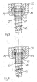
- FIGS. 5 and 6 example shown differs from that in the Figures 1 and 2 shown substantially by the formation of the screw head 140 and its connection to the screw shaft 13th
- the screw head 140 is formed spherical segment having a spherical radius which is substantially equal to the radius of the hollow spherical segment-shaped portion of the receiving part.
- the head further has a recess 141 for engagement with a screwdriver at its flat end facing the first end 2 of the receiving part 1.
- the screw head 140 has a cylindrical neck 142 with an outer diameter that corresponds to the outer diameter of the tubular screw shaft 13. From the neck extends a shoulder 143 with an external thread with which the screw head in the tubular screw shaft 13 is screwed, which is adjacent thereto at its first end 16 on the inner wall has an internal thread 131.
- the connection of the head to the screw shaft is such that the head engages the shaft, while in the first example the head engages around the shaft.
- the screw head 140 in this example may conveniently have a continuous coaxial bore, which is not shown in the figures, and which serves as a channel for introducing active ingredients.
- an internal thread for screwing in the tip 15 is likewise provided on the inner wall, as in the first example.
- the internal thread over the entire length of the tubular threaded shaft may be formed, which is favorable in terms of manufacturing technology and also allows the shortening of the tubular screw shaft to a desired length.
- slots 132 may be provided for engagement with a screwdriver.
- the pressure element 150 has, in contrast to the pressure element 50 of the first example, only short legs 151, 152, which do not protrude laterally beyond the inserted rod 40. Otherwise, as in the first example, the pressure element has a spherical countersink 153 on its head-facing side and a coaxial bore 154.
- an internal screw 160 with an external thread 161 which is the internal thread of the legs corresponds to the receiving part, and provided with a recess for engaging with a screwdriver.
- lock nut 170 is provided.
- the tip is first screwed onto the screw shaft 13. Subsequently, if necessary, bone material is filled into the tubular screw shaft and the head 140 is screwed. Then, the bolt 13 screwed together from each other, tip 15 and head 140 is inserted like a known polyaxial screw in the receiving part 1 and screwed into the bone. If a cannulated head 140 is used, an agent or filler may be injected. Finally, the pressure element is used and the receiving part with the rod by screwing the inner screw 160 and the lock nut 170 firmly connected and thus fixed the angular position of the head in the receiving part.
- the screw shaft has the slits 132 for engaging with a screwdriver, first the screw shaft 13 with screwed-on tip 15 without the head 140 can be screwed. Subsequently, the active ingredient can be filled and placed the receiving part and the screw head are screwed. The connection with the rod then takes place as described above.
- the head and rod fixation is not limited to the variants described. It can be used in the first example, the head and rod fixation of the second example and vice versa. Furthermore, other embodiments, such as the provision of only one acting on the rod inner screw can be provided.
- any shape having openings may be provided.
- the openings may also extend over the entire axial length of the screw shank.
- the head 14 of the first example may be slit at one location throughout in the axial direction. Due to the elasticity thus generated, the head is somewhat compressible, so that it can be introduced from the second end 3 of the receiving part.
- the tip 15 may be self-tapping. Further, the tip may have a coaxially extending through channel for passage of active ingredients.
- the tubular screw shaft 13 may have a suitable length for the particular application, which is optionally produced by cutting a pipe section of desired length of a longer pipe section, and a diameter corresponding to the application.
- the screw can also be designed as a pedicle screw.
- the anchoring element may be combined to stabilize the spine or bone generally via the rod with known anchoring elements.
- the polyaxial connection with the rod 40 is not in the direction of the screw axis, as in the previous examples, but offset laterally to the screw axis.
- the anchoring element comprises a consisting of the tubular screw shaft 13, a tip and the spherical segment 140 head screw member and the head 140 receiving two-piece socket 70 with a screw shaft facing the lower part 71 and a screw shaft facing away upper part 72, which together comprise the rod 40.
- the lower part 71 and the upper part 72 are identical and arranged in mirror image to each other. They each have a central bore 73, 74, which is provided with an internal thread and on which the other part 71, 72 opposite surface has a counterbore. Laterally of the bore 73, 74 is provided at a distance from this one to the other part 71, 72 out of the cylinder segment-shaped recess 75, 76 for holding the rod 40.
- Lower part 71 and upper part 72 of the socket are connected to each other by a screw 81, which is insertable into the internal thread of the upper part, and in the internal thread of the lower part can be screwed.
- the screw 81 In its guided through the upper part 72, the screw 81 has a diameter which is smaller than the diameter of the internal thread of the upper part and has in its guided through the lower part a cooperating with the internal thread of the lower part of external thread.
- the cylinder-segment-shaped recesses 75, 76 and the spherical segment-shaped recesses 77, 78 are dimensioned and arranged to each other that in the state in which the rod 40 and the head 140 are held, the lower part 71 and the upper part 72 are aligned parallel to each other and spaced from each other.
- the implant is particularly suitable for the fixation of fractures on the pelvis and long bones.
- FIG. 7b This in Fig. 7b ) example differs from that in Fig. 7a ) example in that the socket 70 'for detecting two bars 40, 40' has a symmetrically formed in itself lower part 71 'and upper part 72'.
- the lower part 71 'and the upper part 72' are formed symmetrically to a plane defined by the center line of the rods 40, 40 'and the center of the spherical segment-shaped head 140 of the screw and each have two holes 73, 73' and 74, 74 ' , two cylinder segment-shaped recesses 75, 75 'and 76, 76' on.
- the anchoring element consists of a screw element which is formed by the tubular screw shaft 13 with a tip connected to the latter, and of a screw element monoaxially connectable receiving part 90 for receiving a rod 40.
- the receiving part 90 is formed substantially cylindrical and has a recess 91 of U-shaped cross section, which is just sized so large that the rod 40 is inserted and fits into the bottom of the recess.
- two free legs 92, 93 are formed. Adjacent to the free end, the legs 92, 93 on an internal thread 94, which cooperates with a corresponding external thread of a screwed between the legs of the inner screw 95 for fixing the rod 40.
- the receiving part 90 has a threaded shaft 96 for screwing into the tubular shaft 13.
- the anchoring element is first fully assembled, with the tubular shaft filled with active ingredients or bone material when required. Subsequently, the anchoring element is screwed into the bone like a known monoaxial screw. Then the connection via the rod to one or more other anchoring elements. In the correct position, the rod is then fixed over the inner screw.
- the recesses 18 are partially arranged to break the helical tip of the bone thread. As a result, teeth or sharp edges are formed on the bone thread, which have a milling effect when screwed into the bone. However, for certain applications, smooth screwing is desired or required.
- the tubular screw shaft 113 consists of a cylindrical tube having a first end 114 and a second end 115 opposite thereto.
- the tube has, as in the examples of FIGS. 1 to 8 on its outer wall a bone threaded portion 116 with a bone thread for screwing into the bone.
- the bone thread is formed as a self-tapping thread and has in a known manner thread flanks 117, a spiral tip 118, a thread base 119 with a width B and a pitch P.
- the wall of the tubular shaft has a plurality of recesses 120 with a circular Cross-section on.
- the recesses 120 are arranged so that their center lies in the thread root 119 and the diameter D of each recess 120 is smaller than the pitch P and in particular not greater than the width B of the thread base, so that in the in FIGS. 9 and 10 illustrated example, the recesses 120 are completely in the thread root 119 and do not extend into the flanks 117.
- Fig. 9 has the tubular shaft 113 adjacent to the first end 115 a bone thread-free portion 121 with a smooth outer wall, in which no recesses are formed. Further, in the example shown, adjacent to the first end 114 and adjacent to the second end 115 of the tube, there is formed a female threaded portion 122 which serves to connect to the headed and female part, as described in the previous embodiments.
- FIG. 11 shown further modified example differs from that in the FIGS. 9 and 10 Example shown in that the diameter D 'of the recess 120' is greater than the width B of the thread root 119, so that the recesses 120 'hineinerumblen into the flanks 117 of the bone thread, but without breaking the coil tip 118.
- all or a part of the recesses 120, 120 ' are provided on the outside of the wall with a countersink, which forms a surface roughness, which facilitates an ingrowth or growth.
- the diameter of this countersink in the screw axis direction is smaller than the thread pitch P, so that the helical tip 118 is intact.
- the recesses are oval or diamond-shaped. It is crucial that they are arranged in the thread root and that their dimensions are such that the cutting tip of the bone thread is not damaged. Furthermore, it is not necessary to provide recesses in each thread.
- the bone thread portion 116 extends over the entire length of the shaft 113.
- the internal thread 122 may also extend over the entire length.
- the internal thread 122 may also be provided only at one end in a section or not at all. The connection with the other parts of the anchoring element takes place in the case that no internal thread is provided, e.g. over snug fit.
- the tubular screw shaft 125 is not formed as a whole cylindrical, but has a conical bone thread portion 126 which tapers in the direction of the end 127 to be connected to the tip. Adjacent to the conical bone thread portion 126 extends on both sides in each case to the opposite ends 127, 128 each have a cylindrical portion 129, 130 with an internal thread for connection to the tip at one end or with a head or a receiving part, as described above, on other end.
- the cylindrical portion 129 to be connected to the tip is not provided, but the free end of the conical bone thread portion 126 acts as a tip itself.
Landscapes
- Health & Medical Sciences (AREA)
- Orthopedic Medicine & Surgery (AREA)
- Surgery (AREA)
- Life Sciences & Earth Sciences (AREA)
- Heart & Thoracic Surgery (AREA)
- Veterinary Medicine (AREA)
- Engineering & Computer Science (AREA)
- Biomedical Technology (AREA)
- Nuclear Medicine, Radiotherapy & Molecular Imaging (AREA)
- Medical Informatics (AREA)
- Molecular Biology (AREA)
- Animal Behavior & Ethology (AREA)
- General Health & Medical Sciences (AREA)
- Public Health (AREA)
- Neurology (AREA)
- Dentistry (AREA)
- Oral & Maxillofacial Surgery (AREA)
- Surgical Instruments (AREA)
- Prostheses (AREA)
Applications Claiming Priority (2)
| Application Number | Priority Date | Filing Date | Title |
|---|---|---|---|
| DE10246177A DE10246177A1 (de) | 2002-10-02 | 2002-10-02 | Verankerungselement |
| EP02795258A EP1443866B1 (de) | 2002-10-02 | 2002-12-20 | Knochenverankerungselement |
Related Parent Applications (1)
| Application Number | Title | Priority Date | Filing Date |
|---|---|---|---|
| EP02795258A Division EP1443866B1 (de) | 2002-10-02 | 2002-12-20 | Knochenverankerungselement |
Publications (2)
| Publication Number | Publication Date |
|---|---|
| EP1681024A1 EP1681024A1 (de) | 2006-07-19 |
| EP1681024B1 true EP1681024B1 (de) | 2008-06-25 |
Family
ID=37252235
Family Applications (2)
| Application Number | Title | Priority Date | Filing Date |
|---|---|---|---|
| EP02795258A Expired - Lifetime EP1443866B1 (de) | 2002-10-02 | 2002-12-20 | Knochenverankerungselement |
| EP06005740A Expired - Lifetime EP1681024B1 (de) | 2002-10-02 | 2002-12-20 | Knochenverankerungselement |
Family Applications Before (1)
| Application Number | Title | Priority Date | Filing Date |
|---|---|---|---|
| EP02795258A Expired - Lifetime EP1443866B1 (de) | 2002-10-02 | 2002-12-20 | Knochenverankerungselement |
Country Status (7)
| Country | Link |
|---|---|
| US (1) | US9848892B2 (ko) |
| EP (2) | EP1443866B1 (ko) |
| JP (2) | JP4437086B2 (ko) |
| KR (1) | KR100996240B1 (ko) |
| AU (1) | AU2002360070A1 (ko) |
| DE (3) | DE10246177A1 (ko) |
| WO (1) | WO2004032774A1 (ko) |
Families Citing this family (218)
| Publication number | Priority date | Publication date | Assignee | Title |
|---|---|---|---|---|
| US7833250B2 (en) | 2004-11-10 | 2010-11-16 | Jackson Roger P | Polyaxial bone screw with helically wound capture connection |
| US20060025771A1 (en) * | 2000-08-23 | 2006-02-02 | Jackson Roger P | Helical reverse angle guide and advancement structure with break-off extensions |
| US20060083603A1 (en) * | 2000-08-23 | 2006-04-20 | Jackson Roger P | Reverse angled threadform with anti-splay clearance |
| US7837716B2 (en) * | 2000-08-23 | 2010-11-23 | Jackson Roger P | Threadform for medical implant closure |
| US6726689B2 (en) * | 2002-09-06 | 2004-04-27 | Roger P. Jackson | Helical interlocking mating guide and advancement structure |
| US8377100B2 (en) * | 2000-12-08 | 2013-02-19 | Roger P. Jackson | Closure for open-headed medical implant |
| US8292926B2 (en) | 2005-09-30 | 2012-10-23 | Jackson Roger P | Dynamic stabilization connecting member with elastic core and outer sleeve |
| US10729469B2 (en) | 2006-01-09 | 2020-08-04 | Roger P. Jackson | Flexible spinal stabilization assembly with spacer having off-axis core member |
| US8353932B2 (en) | 2005-09-30 | 2013-01-15 | Jackson Roger P | Polyaxial bone anchor assembly with one-piece closure, pressure insert and plastic elongate member |
| US7862587B2 (en) | 2004-02-27 | 2011-01-04 | Jackson Roger P | Dynamic stabilization assemblies, tool set and method |
| US10258382B2 (en) | 2007-01-18 | 2019-04-16 | Roger P. Jackson | Rod-cord dynamic connection assemblies with slidable bone anchor attachment members along the cord |
| US6740086B2 (en) | 2002-04-18 | 2004-05-25 | Spinal Innovations, Llc | Screw and rod fixation assembly and device |
| US8282673B2 (en) | 2002-09-06 | 2012-10-09 | Jackson Roger P | Anti-splay medical implant closure with multi-surface removal aperture |
| US8876868B2 (en) * | 2002-09-06 | 2014-11-04 | Roger P. Jackson | Helical guide and advancement flange with radially loaded lip |
| US8257402B2 (en) * | 2002-09-06 | 2012-09-04 | Jackson Roger P | Closure for rod receiving orthopedic implant having left handed thread removal |
| US20060009773A1 (en) * | 2002-09-06 | 2006-01-12 | Jackson Roger P | Helical interlocking mating guide and advancement structure |
| DE10260222B4 (de) * | 2002-12-20 | 2008-01-03 | Biedermann Motech Gmbh | Rohrförmiges Element für ein in der Wirbelsäulen- oder der Knochenchirurgie zu verwendendes Implantat und Implantat mit einem solchen Element |
| US7621918B2 (en) | 2004-11-23 | 2009-11-24 | Jackson Roger P | Spinal fixation tool set and method |
| US8540753B2 (en) | 2003-04-09 | 2013-09-24 | Roger P. Jackson | Polyaxial bone screw with uploaded threaded shank and method of assembly and use |
| US6716214B1 (en) * | 2003-06-18 | 2004-04-06 | Roger P. Jackson | Polyaxial bone screw with spline capture connection |
| US7354442B2 (en) * | 2003-05-05 | 2008-04-08 | Warsaw Orthopedic, Inc. | Bone anchor and methods of using the same |
| US7377923B2 (en) * | 2003-05-22 | 2008-05-27 | Alphatec Spine, Inc. | Variable angle spinal screw assembly |
| US8137386B2 (en) | 2003-08-28 | 2012-03-20 | Jackson Roger P | Polyaxial bone screw apparatus |
| US8398682B2 (en) | 2003-06-18 | 2013-03-19 | Roger P. Jackson | Polyaxial bone screw assembly |
| US7776067B2 (en) * | 2005-05-27 | 2010-08-17 | Jackson Roger P | Polyaxial bone screw with shank articulation pressure insert and method |
| US8257398B2 (en) | 2003-06-18 | 2012-09-04 | Jackson Roger P | Polyaxial bone screw with cam capture |
| US7967850B2 (en) | 2003-06-18 | 2011-06-28 | Jackson Roger P | Polyaxial bone anchor with helical capture connection, insert and dual locking assembly |
| US8366753B2 (en) * | 2003-06-18 | 2013-02-05 | Jackson Roger P | Polyaxial bone screw assembly with fixed retaining structure |
| US8926670B2 (en) | 2003-06-18 | 2015-01-06 | Roger P. Jackson | Polyaxial bone screw assembly |
| US8092500B2 (en) | 2007-05-01 | 2012-01-10 | Jackson Roger P | Dynamic stabilization connecting member with floating core, compression spacer and over-mold |
| US8377102B2 (en) | 2003-06-18 | 2013-02-19 | Roger P. Jackson | Polyaxial bone anchor with spline capture connection and lower pressure insert |
| US7766915B2 (en) | 2004-02-27 | 2010-08-03 | Jackson Roger P | Dynamic fixation assemblies with inner core and outer coil-like member |
| US7179261B2 (en) | 2003-12-16 | 2007-02-20 | Depuy Spine, Inc. | Percutaneous access devices and bone anchor assemblies |
| US11419642B2 (en) | 2003-12-16 | 2022-08-23 | Medos International Sarl | Percutaneous access devices and bone anchor assemblies |
| US7527638B2 (en) | 2003-12-16 | 2009-05-05 | Depuy Spine, Inc. | Methods and devices for minimally invasive spinal fixation element placement |
| US9050148B2 (en) | 2004-02-27 | 2015-06-09 | Roger P. Jackson | Spinal fixation tool attachment structure |
| US7160300B2 (en) | 2004-02-27 | 2007-01-09 | Jackson Roger P | Orthopedic implant rod reduction tool set and method |
| US8152810B2 (en) | 2004-11-23 | 2012-04-10 | Jackson Roger P | Spinal fixation tool set and method |
| JP2007525274A (ja) | 2004-02-27 | 2007-09-06 | ロジャー・ピー・ジャクソン | 整形外科インプラントロッド整復器具セット及び方法 |
| US11241261B2 (en) | 2005-09-30 | 2022-02-08 | Roger P Jackson | Apparatus and method for soft spinal stabilization using a tensionable cord and releasable end structure |
| US8475495B2 (en) * | 2004-04-08 | 2013-07-02 | Globus Medical | Polyaxial screw |
| US7503924B2 (en) * | 2004-04-08 | 2009-03-17 | Globus Medical, Inc. | Polyaxial screw |
| US8728132B2 (en) * | 2004-04-20 | 2014-05-20 | James L. Chappuis | Internal pedicle insulator apparatus and method of use |
| US20180228621A1 (en) | 2004-08-09 | 2018-08-16 | Mark A. Reiley | Apparatus, systems, and methods for the fixation or fusion of bone |
| US7186255B2 (en) * | 2004-08-12 | 2007-03-06 | Atlas Spine, Inc. | Polyaxial screw |
| US7651502B2 (en) | 2004-09-24 | 2010-01-26 | Jackson Roger P | Spinal fixation tool set and method for rod reduction and fastener insertion |
| US8926672B2 (en) | 2004-11-10 | 2015-01-06 | Roger P. Jackson | Splay control closure for open bone anchor |
| EP1811911A4 (en) | 2004-11-10 | 2012-01-11 | Roger P Jackson | SPIRAL GUIDANCE AND ADVANCE FLANGE WITH CANCEL EXTENSIONS |
| US7572279B2 (en) * | 2004-11-10 | 2009-08-11 | Jackson Roger P | Polyaxial bone screw with discontinuous helically wound capture connection |
| US8308782B2 (en) | 2004-11-23 | 2012-11-13 | Jackson Roger P | Bone anchors with longitudinal connecting member engaging inserts and closures for fixation and optional angulation |
| US9980753B2 (en) | 2009-06-15 | 2018-05-29 | Roger P Jackson | pivotal anchor with snap-in-place insert having rotation blocking extensions |
| US7875065B2 (en) * | 2004-11-23 | 2011-01-25 | Jackson Roger P | Polyaxial bone screw with multi-part shank retainer and pressure insert |
| US9216041B2 (en) | 2009-06-15 | 2015-12-22 | Roger P. Jackson | Spinal connecting members with tensioned cords and rigid sleeves for engaging compression inserts |
| US8444681B2 (en) | 2009-06-15 | 2013-05-21 | Roger P. Jackson | Polyaxial bone anchor with pop-on shank, friction fit retainer and winged insert |
| US9393047B2 (en) | 2009-06-15 | 2016-07-19 | Roger P. Jackson | Polyaxial bone anchor with pop-on shank and friction fit retainer with low profile edge lock |
| US9168069B2 (en) | 2009-06-15 | 2015-10-27 | Roger P. Jackson | Polyaxial bone anchor with pop-on shank and winged insert with lower skirt for engaging a friction fit retainer |
| US8172855B2 (en) | 2004-11-24 | 2012-05-08 | Abdou M S | Devices and methods for inter-vertebral orthopedic device placement |
| US7722620B2 (en) | 2004-12-06 | 2010-05-25 | Dfine, Inc. | Bone treatment systems and methods |
| US20060155286A1 (en) * | 2005-01-11 | 2006-07-13 | Chao-Jan Wang | Bone securing bolt |
| US7901437B2 (en) | 2007-01-26 | 2011-03-08 | Jackson Roger P | Dynamic stabilization member with molded connection |
| US10076361B2 (en) | 2005-02-22 | 2018-09-18 | Roger P. Jackson | Polyaxial bone screw with spherical capture, compression and alignment and retention structures |
| US8167913B2 (en) * | 2005-03-03 | 2012-05-01 | Altus Partners, Llc | Spinal stabilization using bone anchor and anchor seat with tangential locking feature |
| WO2006096381A2 (en) * | 2005-03-03 | 2006-09-14 | Accelerated Innovation Llc | Spinal stabilization using bone anchor seat and cross coupling with improved locking feature |
| US20060241593A1 (en) * | 2005-04-08 | 2006-10-26 | Sdgi Holdings, Inc. | Multi-piece vertebral attachment device |
| US8221472B2 (en) | 2005-04-25 | 2012-07-17 | Synthes Usa, Llc | Bone anchor with locking cap and method of spinal fixation |
| US7951198B2 (en) * | 2005-05-10 | 2011-05-31 | Acumed Llc | Bone connector with pivotable joint |
| US20070055257A1 (en) * | 2005-06-30 | 2007-03-08 | Alex Vaccaro | Cannulated screw access system |
| KR101147452B1 (ko) * | 2005-07-08 | 2012-05-21 | 비이더만 모테크 게엠베하 & 코. 카게 | 뼈 고정 장치 |
| DE602005016791D1 (de) | 2005-07-08 | 2009-11-05 | Biedermann Motech Gmbh | Knochenverankerungsvorrichtung |
| KR101145415B1 (ko) * | 2005-07-08 | 2012-05-15 | 비이더만 모테크 게엠베하 & 코. 카게 | 뼈 고정 요소 |
| DE602005002477T2 (de) * | 2005-07-12 | 2008-01-17 | Biedermann Motech Gmbh | Knochenverankerungsvorrichtung |
| CN1907240B (zh) | 2005-08-03 | 2011-03-16 | 比德曼莫泰赫有限公司 | 骨锚固件 |
| US8105368B2 (en) | 2005-09-30 | 2012-01-31 | Jackson Roger P | Dynamic stabilization connecting member with slitted core and outer sleeve |
| US8002806B2 (en) * | 2005-10-20 | 2011-08-23 | Warsaw Orthopedic, Inc. | Bottom loading multi-axial screw assembly |
| US8100946B2 (en) | 2005-11-21 | 2012-01-24 | Synthes Usa, Llc | Polyaxial bone anchors with increased angulation |
| US7704271B2 (en) | 2005-12-19 | 2010-04-27 | Abdou M Samy | Devices and methods for inter-vertebral orthopedic device placement |
| US20090204155A1 (en) * | 2005-12-19 | 2009-08-13 | Felix Aschmann | Polyaxial bone anchor with headless pedicle screw |
| US20080015576A1 (en) * | 2006-04-28 | 2008-01-17 | Whipple Dale E | Large diameter bone anchor assembly |
| US20080015596A1 (en) * | 2006-04-28 | 2008-01-17 | Whipple Dale E | Large diameter multiple piece bone anchor assembly |
| US8361129B2 (en) | 2006-04-28 | 2013-01-29 | Depuy Spine, Inc. | Large diameter bone anchor assembly |
| US8133262B2 (en) * | 2006-04-28 | 2012-03-13 | Depuy Spine, Inc. | Large diameter bone anchor assembly |
| US8821506B2 (en) | 2006-05-11 | 2014-09-02 | Michael David Mitchell | Bone screw |
| WO2007138659A1 (ja) | 2006-05-26 | 2007-12-06 | National University Corporation Nagoya University | 創外固定器 |
| US20070288014A1 (en) * | 2006-06-06 | 2007-12-13 | Shadduck John H | Spine treatment devices and methods |
| US20080021465A1 (en) * | 2006-07-20 | 2008-01-24 | Shadduck John H | Spine treatment devices and methods |
| US8894661B2 (en) * | 2007-08-16 | 2014-11-25 | Smith & Nephew, Inc. | Helicoil interference fixation system for attaching a graft ligament to a bone |
| ES2453196T3 (es) * | 2006-08-24 | 2014-04-04 | Biedermann Technologies Gmbh & Co. Kg | Dispositivo de anclaje óseo |
| US8167910B2 (en) | 2006-10-16 | 2012-05-01 | Innovative Delta Technology Llc | Bone screw and associated assembly and methods of use thereof |
| KR101538135B1 (ko) * | 2006-11-10 | 2015-07-29 | 비이더만 테크놀로지스 게엠베하 & 코. 카게 | 뼈 고정 네일 |
| DE602006007475D1 (de) | 2006-11-10 | 2009-08-06 | Biedermann Motech Gmbh | Knochenverankerungsnagel |
| EP2272451B1 (en) * | 2006-11-22 | 2012-04-04 | BIEDERMANN MOTECH GmbH | Bone anchoring device |
| JP2010512178A (ja) * | 2006-12-08 | 2010-04-22 | ロジャー・ピー・ジャクソン | 動的脊椎インプラントのためのツールシステム |
| US7794478B2 (en) | 2007-01-15 | 2010-09-14 | Innovative Delta Technology, Llc | Polyaxial cross connector and methods of use thereof |
| US9962194B2 (en) | 2007-01-15 | 2018-05-08 | Innovative Delta Technology, Llc | Polyaxial spinal stabilizer connector and methods of use thereof |
| US9451989B2 (en) | 2007-01-18 | 2016-09-27 | Roger P Jackson | Dynamic stabilization members with elastic and inelastic sections |
| US8366745B2 (en) | 2007-05-01 | 2013-02-05 | Jackson Roger P | Dynamic stabilization assembly having pre-compressed spacers with differential displacements |
| US8475498B2 (en) | 2007-01-18 | 2013-07-02 | Roger P. Jackson | Dynamic stabilization connecting member with cord connection |
| US10792074B2 (en) | 2007-01-22 | 2020-10-06 | Roger P. Jackson | Pivotal bone anchor assemly with twist-in-place friction fit insert |
| US8012177B2 (en) | 2007-02-12 | 2011-09-06 | Jackson Roger P | Dynamic stabilization assembly with frusto-conical connection |
| US20080208260A1 (en) * | 2007-02-22 | 2008-08-28 | Csaba Truckai | Spine treatment devices and methods |
| US8894685B2 (en) | 2007-04-13 | 2014-11-25 | DePuy Synthes Products, LLC | Facet fixation and fusion screw and washer assembly and method of use |
| US7922725B2 (en) | 2007-04-19 | 2011-04-12 | Zimmer Spine, Inc. | Method and associated instrumentation for installation of spinal dynamic stabilization system |
| US10383660B2 (en) | 2007-05-01 | 2019-08-20 | Roger P. Jackson | Soft stabilization assemblies with pretensioned cords |
| US8197517B1 (en) | 2007-05-08 | 2012-06-12 | Theken Spine, Llc | Frictional polyaxial screw assembly |
| US7942909B2 (en) | 2009-08-13 | 2011-05-17 | Ortho Innovations, Llc | Thread-thru polyaxial pedicle screw system |
| US7942910B2 (en) | 2007-05-16 | 2011-05-17 | Ortho Innovations, Llc | Polyaxial bone screw |
| US7951173B2 (en) * | 2007-05-16 | 2011-05-31 | Ortho Innovations, Llc | Pedicle screw implant system |
| US7947065B2 (en) | 2008-11-14 | 2011-05-24 | Ortho Innovations, Llc | Locking polyaxial ball and socket fastener |
| US8197518B2 (en) | 2007-05-16 | 2012-06-12 | Ortho Innovations, Llc | Thread-thru polyaxial pedicle screw system |
| US7942911B2 (en) | 2007-05-16 | 2011-05-17 | Ortho Innovations, Llc | Polyaxial bone screw |
| WO2008153827A1 (en) | 2007-05-31 | 2008-12-18 | Jackson Roger P | Dynamic stabilization connecting member with pre-tensioned solid core |
| US20090012572A1 (en) * | 2007-07-02 | 2009-01-08 | Ming-Chau Chang | Cannular Bolt |
| US9439681B2 (en) | 2007-07-20 | 2016-09-13 | DePuy Synthes Products, Inc. | Polyaxial bone fixation element |
| US9597118B2 (en) * | 2007-07-20 | 2017-03-21 | Dfine, Inc. | Bone anchor apparatus and method |
| US9044333B2 (en) | 2007-07-27 | 2015-06-02 | R Tree Innovations, Llc | Inter-body implantation system and method |
| US8894651B2 (en) * | 2007-09-11 | 2014-11-25 | Kamran Aflatoon | Method of lateral facet approach, decompression and fusion using screws and staples as well as arthroplasty |
| US8323322B2 (en) * | 2007-10-05 | 2012-12-04 | Zimmer Spine, Inc. | Medical implant formed from porous metal and method |
| US8911477B2 (en) | 2007-10-23 | 2014-12-16 | Roger P. Jackson | Dynamic stabilization member with end plate support and cable core extension |
| US9579126B2 (en) | 2008-02-02 | 2017-02-28 | Globus Medical, Inc. | Spinal rod link reducer |
| US8007522B2 (en) | 2008-02-04 | 2011-08-30 | Depuy Spine, Inc. | Methods for correction of spinal deformities |
| US9277940B2 (en) * | 2008-02-05 | 2016-03-08 | Zimmer Spine, Inc. | System and method for insertion of flexible spinal stabilization element |
| CA2739997C (en) | 2008-08-01 | 2013-08-13 | Roger P. Jackson | Longitudinal connecting member with sleeved tensioned cords |
| ES2387512T3 (es) * | 2008-09-05 | 2012-09-25 | Biedermann Technologies Gmbh & Co. Kg | Dispositivo de estabilización para huesos, en particular para la columna vertebral |
| KR20110073438A (ko) | 2008-09-12 | 2011-06-29 | 신세스 게엠바하 | 척추 안정화 및 안내 고정 시스템 |
| EP2339975B1 (en) | 2008-09-29 | 2015-03-25 | Synthes GmbH | Polyaxial bottom-loading screw and rod assembly |
| US20100114174A1 (en) | 2008-10-30 | 2010-05-06 | Bryan Jones | Systems and Methods for Delivering Bone Cement to a Bone Anchor |
| EP3682828B1 (en) | 2008-11-03 | 2024-01-24 | Synthes GmbH | Uni-planar bone fixation assembly |
| JP4919120B2 (ja) | 2009-03-03 | 2012-04-18 | 株式会社デンソー | バッテリの状態検出装置 |
| EP2419031B1 (en) | 2009-04-15 | 2016-11-30 | Synthes GmbH | Revision connector for spinal constructs |
| CA2759445A1 (en) * | 2009-04-20 | 2010-10-28 | Osteo Innovations Llc | System and method for self filling bone screws |
| US11229457B2 (en) | 2009-06-15 | 2022-01-25 | Roger P. Jackson | Pivotal bone anchor assembly with insert tool deployment |
| US8998959B2 (en) | 2009-06-15 | 2015-04-07 | Roger P Jackson | Polyaxial bone anchors with pop-on shank, fully constrained friction fit retainer and lock and release insert |
| US9668771B2 (en) | 2009-06-15 | 2017-06-06 | Roger P Jackson | Soft stabilization assemblies with off-set connector |
| EP2757988A4 (en) | 2009-06-15 | 2015-08-19 | Jackson Roger P | POLYAXIAL BONE ANCHORING DEVICE WITH PRESSURE-INPUT ROD AND FRICTION-ADJUSTING COMPRESSION-SIZE CLAMP FIN |
| US8236035B1 (en) | 2009-06-16 | 2012-08-07 | Bedor Bernard M | Spinal fixation system and method |
| CA2764841A1 (en) | 2009-06-17 | 2010-12-23 | Synthes Usa, Llc | Revision connector for spinal constructs |
| JP5643305B2 (ja) * | 2009-07-09 | 2014-12-17 | アール ツリー イノベーションズ エルエルシー | 可撓性を有する椎体間装置 |
| US8574273B2 (en) | 2009-09-09 | 2013-11-05 | Innovision, Inc. | Bone screws and methods of use thereof |
| EP2485654B1 (en) | 2009-10-05 | 2021-05-05 | Jackson P. Roger | Polyaxial bone anchor with non-pivotable retainer and pop-on shank, some with friction fit |
| US8361123B2 (en) | 2009-10-16 | 2013-01-29 | Depuy Spine, Inc. | Bone anchor assemblies and methods of manufacturing and use thereof |
| EP2329780B1 (en) * | 2009-12-03 | 2013-02-20 | Biedermann Technologies GmbH & Co. KG | Bone screw |
| EP2329781B1 (en) * | 2009-12-03 | 2015-03-04 | Biedermann Technologies GmbH & Co. KG | Bone screw |
| US8764806B2 (en) | 2009-12-07 | 2014-07-01 | Samy Abdou | Devices and methods for minimally invasive spinal stabilization and instrumentation |
| EP2361574B1 (en) | 2010-02-26 | 2014-01-08 | Biedermann Technologies GmbH & Co. KG | Bone screw |
| US9084634B1 (en) | 2010-07-09 | 2015-07-21 | Theken Spine, Llc | Uniplanar screw |
| US10603083B1 (en) | 2010-07-09 | 2020-03-31 | Theken Spine, Llc | Apparatus and method for limiting a range of angular positions of a screw |
| US9044277B2 (en) | 2010-07-12 | 2015-06-02 | DePuy Synthes Products, Inc. | Pedicular facet fusion screw with plate |
| WO2012030712A1 (en) | 2010-08-30 | 2012-03-08 | Zimmer Spine, Inc. | Polyaxial pedicle screw |
| CA2822964A1 (en) * | 2010-11-02 | 2012-05-10 | Roger P. Jackson | Polyaxial bone anchor with pop-on shank and pivotable retainer |
| EP2460484A1 (de) * | 2010-12-01 | 2012-06-06 | FACET-LINK Inc. | Winkelvariable Knochenschauben-Fixationsanordnung |
| US20120215263A1 (en) * | 2011-02-23 | 2012-08-23 | Choon Sung Lee | Extensible pedicle screw coupling device |
| WO2012128825A1 (en) | 2011-03-24 | 2012-09-27 | Jackson Roger P | Polyaxial bone anchor with compound articulation and pop-on shank |
| US9131962B2 (en) | 2011-05-24 | 2015-09-15 | Globus Medical, Inc. | Bone screw assembly |
| US9198694B2 (en) | 2011-07-15 | 2015-12-01 | Globus Medical, Inc. | Orthopedic fixation devices and methods of installation thereof |
| US9358047B2 (en) | 2011-07-15 | 2016-06-07 | Globus Medical, Inc. | Orthopedic fixation devices and methods of installation thereof |
| US9186187B2 (en) | 2011-07-15 | 2015-11-17 | Globus Medical, Inc. | Orthopedic fixation devices and methods of installation thereof |
| US9993269B2 (en) | 2011-07-15 | 2018-06-12 | Globus Medical, Inc. | Orthopedic fixation devices and methods of installation thereof |
| US8888827B2 (en) | 2011-07-15 | 2014-11-18 | Globus Medical, Inc. | Orthopedic fixation devices and methods of installation thereof |
| US9155580B2 (en) | 2011-08-25 | 2015-10-13 | Medos International Sarl | Multi-threaded cannulated bone anchors |
| US8845728B1 (en) | 2011-09-23 | 2014-09-30 | Samy Abdou | Spinal fixation devices and methods of use |
| WO2013106217A1 (en) | 2012-01-10 | 2013-07-18 | Jackson, Roger, P. | Multi-start closures for open implants |
| US20130226240A1 (en) | 2012-02-22 | 2013-08-29 | Samy Abdou | Spinous process fixation devices and methods of use |
| US10363140B2 (en) | 2012-03-09 | 2019-07-30 | Si-Bone Inc. | Systems, device, and methods for joint fusion |
| IN2014DN06946A (ko) | 2012-03-09 | 2015-04-10 | Si Bone Inc | |
| BR112014027319A2 (pt) | 2012-05-04 | 2017-06-27 | Si Bone Inc | implante fenestrado |
| EP2910210B1 (en) | 2012-06-18 | 2018-03-07 | Biedermann Technologies GmbH & Co. KG | Bone anchor |
| US9198767B2 (en) | 2012-08-28 | 2015-12-01 | Samy Abdou | Devices and methods for spinal stabilization and instrumentation |
| US9782204B2 (en) | 2012-09-28 | 2017-10-10 | Medos International Sarl | Bone anchor assemblies |
| US9320617B2 (en) | 2012-10-22 | 2016-04-26 | Cogent Spine, LLC | Devices and methods for spinal stabilization and instrumentation |
| US8911478B2 (en) | 2012-11-21 | 2014-12-16 | Roger P. Jackson | Splay control closure for open bone anchor |
| US10058354B2 (en) | 2013-01-28 | 2018-08-28 | Roger P. Jackson | Pivotal bone anchor assembly with frictional shank head seating surfaces |
| US8852239B2 (en) | 2013-02-15 | 2014-10-07 | Roger P Jackson | Sagittal angle screw with integral shank and receiver |
| US10342582B2 (en) | 2013-03-14 | 2019-07-09 | DePuy Synthes Products, Inc. | Bone anchor assemblies and methods with improved locking |
| US20140277153A1 (en) | 2013-03-14 | 2014-09-18 | DePuy Synthes Products, LLC | Bone Anchor Assemblies and Methods With Improved Locking |
| US9775660B2 (en) | 2013-03-14 | 2017-10-03 | DePuy Synthes Products, Inc. | Bottom-loading bone anchor assemblies and methods |
| US9724145B2 (en) | 2013-03-14 | 2017-08-08 | Medos International Sarl | Bone anchor assemblies with multiple component bottom loading bone anchors |
| US9259247B2 (en) | 2013-03-14 | 2016-02-16 | Medos International Sarl | Locking compression members for use with bone anchor assemblies and methods |
| US9936983B2 (en) | 2013-03-15 | 2018-04-10 | Si-Bone Inc. | Implants for spinal fixation or fusion |
| DE102014219270A1 (de) | 2013-10-01 | 2015-04-16 | Silony Medical International AG | Polyaxialknochenschraube für chirurgisch medizinische Zwecke und Osteosynthesevorrichtung |
| EP2859856B1 (en) | 2013-10-11 | 2017-12-13 | Biedermann Technologies GmbH & Co. KG | Bone screw with self-constrained flexibility |
| US9566092B2 (en) | 2013-10-29 | 2017-02-14 | Roger P. Jackson | Cervical bone anchor with collet retainer and outer locking sleeve |
| US9717533B2 (en) | 2013-12-12 | 2017-08-01 | Roger P. Jackson | Bone anchor closure pivot-splay control flange form guide and advancement structure |
| US9451993B2 (en) | 2014-01-09 | 2016-09-27 | Roger P. Jackson | Bi-radial pop-on cervical bone anchor |
| US9597119B2 (en) | 2014-06-04 | 2017-03-21 | Roger P. Jackson | Polyaxial bone anchor with polymer sleeve |
| US10064658B2 (en) | 2014-06-04 | 2018-09-04 | Roger P. Jackson | Polyaxial bone anchor with insert guides |
| WO2016044731A1 (en) | 2014-09-18 | 2016-03-24 | Si-Bone Inc. | Implants for bone fixation or fusion |
| US9579123B2 (en) * | 2014-09-19 | 2017-02-28 | Globus Medical, Inc. | Orthopedic stabilization devices and methods for installation thereof |
| DE102015008036A1 (de) | 2015-06-09 | 2016-12-15 | Signus Medizintechnik Gmbh | Pedikelschraube mit Tulpe |
| EP3115008B1 (de) | 2015-07-09 | 2019-06-19 | Silony Medical International AG | Knochenverankerungselement |
| US9895169B2 (en) * | 2015-08-21 | 2018-02-20 | Globus Medical, Inc. | Self in-fusing pedicle screw implant |
| RU2018116877A (ru) * | 2015-10-09 | 2019-11-07 | Линкспайн, Инк. | Спинальная многоуровневая система стабилизации фасеточного сустава |
| US10857003B1 (en) | 2015-10-14 | 2020-12-08 | Samy Abdou | Devices and methods for vertebral stabilization |
| AU2016247221B2 (en) * | 2015-10-23 | 2021-03-11 | K2M, Inc. | Semi-constrained bone screw and insertion instrument |
| US10383663B2 (en) | 2016-03-29 | 2019-08-20 | Globus Medical, Inc. | Revision connectors, systems and methods thereof |
| US10624679B2 (en) | 2016-03-29 | 2020-04-21 | Globus Medical, Inc. | Revision connectors, systems and methods thereof |
| US9980755B2 (en) | 2016-03-29 | 2018-05-29 | Globus Medical, Inc. | Revision connectors, systems, and methods thereof |
| US10307185B2 (en) | 2016-03-29 | 2019-06-04 | Globus Medical, Inc. | Revision connectors, systems, and methods thereof |
| WO2018039485A1 (en) | 2016-08-24 | 2018-03-01 | Integrity Implants, Inc. | Adjustable bone fixation systems |
| US10744000B1 (en) | 2016-10-25 | 2020-08-18 | Samy Abdou | Devices and methods for vertebral bone realignment |
| US10973648B1 (en) | 2016-10-25 | 2021-04-13 | Samy Abdou | Devices and methods for vertebral bone realignment |
| KR101911081B1 (ko) * | 2016-12-07 | 2018-10-23 | 박지훈 | 치과용 임플란트 |
| WO2019067584A1 (en) | 2017-09-26 | 2019-04-04 | Si-Bone Inc. | SYSTEMS AND METHODS FOR DECORTICATING SACROILITIC JOINT |
| US10507043B1 (en) | 2017-10-11 | 2019-12-17 | Seaspine Orthopedics Corporation | Collet for a polyaxial screw assembly |
| US10631905B2 (en) | 2017-10-31 | 2020-04-28 | Sicage Llc | Bone cage with helically arranged fenestrations |
| EP3563784B1 (en) * | 2018-05-03 | 2022-02-16 | K2M, Inc. | Head to head transverse connector |
| WO2020008309A1 (en) * | 2018-07-01 | 2020-01-09 | Petric Zoran Lee | A bone implant |
| EP4008283A1 (en) | 2018-08-24 | 2022-06-08 | Blue Sky Technologies, LLC | Surgical fastener |
| JP6979051B2 (ja) * | 2018-08-27 | 2021-12-08 | グローバス メディカル インコーポレイティッド | 骨固定のためのねじインプラント |
| US11179248B2 (en) | 2018-10-02 | 2021-11-23 | Samy Abdou | Devices and methods for spinal implantation |
| WO2020168269A1 (en) | 2019-02-14 | 2020-08-20 | Si-Bone Inc. | Implants for spinal fixation and or fusion |
| US11369419B2 (en) | 2019-02-14 | 2022-06-28 | Si-Bone Inc. | Implants for spinal fixation and or fusion |
| US20220160400A1 (en) * | 2019-03-12 | 2022-05-26 | Carbofix Spine Inc. | Composite material spinal implant |
| EP4065015A4 (en) | 2019-11-27 | 2024-01-03 | Si Bone Inc | BONE STABILIZATION IMPLANTS AND METHODS OF PLACEMENT THROUGH IF JOINTS |
| WO2021127251A1 (en) * | 2019-12-17 | 2021-06-24 | Jackson Roger P | Bone anchor assembly with closed ring retainer and internal snap ring |
| US20240041499A1 (en) * | 2020-10-23 | 2024-02-08 | Carbofix Spine Inc. | Composite material devices for connecting an orthopedic rod to a pedicle screw and supplemental tools |
| JP2023553120A (ja) | 2020-12-09 | 2023-12-20 | エスアイ-ボーン・インコーポレイテッド | 仙腸関節安定化インプラントおよびインプラント方法 |
| CN113768603A (zh) * | 2021-09-16 | 2021-12-10 | 右江民族医学院附属医院 | 万向椎弓根螺钉固定装置及其安装工具 |
| US11690652B1 (en) | 2022-08-17 | 2023-07-04 | Zavation Medical Products Llc | Modular screw assembly |
Family Cites Families (67)
| Publication number | Priority date | Publication date | Assignee | Title |
|---|---|---|---|---|
| US1394608A (en) * | 1920-04-29 | 1921-10-25 | Frederick E Buchser | Tool |
| US2293950A (en) | 1939-07-13 | 1942-08-25 | Westinghouse Electric & Mfg Co | Electric protective device |
| US2292102A (en) * | 1940-09-30 | 1942-08-04 | John P Cluett | Insulating bushing |
| US2993950A (en) * | 1959-06-17 | 1961-07-25 | Formar Ind Inc | Self-tapping non-conductive fastener |
| US3057285A (en) * | 1960-06-13 | 1962-10-09 | Everett T Wheeler | Ventilating fastener for fastening weather-protecting boards to walls |
| CH648197A5 (de) * | 1980-05-28 | 1985-03-15 | Synthes Ag | Implantat und zu dessen befestigung an einem knochen dienende schrauben. |
| CH672058A5 (ko) * | 1986-08-05 | 1989-10-31 | Synthes Ag | |
| US5330536A (en) | 1987-09-18 | 1994-07-19 | Howmedica Gmbh | Femur portion of a hip |
| US5015247A (en) | 1988-06-13 | 1991-05-14 | Michelson Gary K | Threaded spinal implant |
| US6120502A (en) | 1988-06-13 | 2000-09-19 | Michelson; Gary Karlin | Apparatus and method for the delivery of electrical current for interbody spinal arthrodesis |
| CA1333209C (en) | 1988-06-28 | 1994-11-29 | Gary Karlin Michelson | Artificial spinal fusion implants |
| US4961740B1 (en) | 1988-10-17 | 1997-01-14 | Surgical Dynamics Inc | V-thread fusion cage and method of fusing a bone joint |
| US5458638A (en) | 1989-07-06 | 1995-10-17 | Spine-Tech, Inc. | Non-threaded spinal implant |
| DE3936703A1 (de) * | 1989-11-03 | 1991-05-08 | Lutz Biedermann | Knochenschraube |
| SE9001521D0 (sv) | 1990-04-26 | 1990-04-26 | Per Ingvar Branemark | System och metod foer rekonstruktion av leder, i synnerhet handleder |
| US5246458A (en) | 1992-10-07 | 1993-09-21 | Graham Donald V | Artificial disk |
| DE4307576C1 (de) * | 1993-03-10 | 1994-04-21 | Biedermann Motech Gmbh | Knochenschraube |
| CA2093900C (en) | 1993-04-13 | 1996-12-10 | Norman H. K. Kwan | Dental implant having cutting means |
| US5584831A (en) * | 1993-07-09 | 1996-12-17 | September 28, Inc. | Spinal fixation device and method |
| JPH0751292A (ja) | 1993-08-16 | 1995-02-28 | Yoshihiro Kishigami | 骨内留置用骨ネジ |
| US5507817A (en) | 1994-02-22 | 1996-04-16 | Kirschner Medical Corporation | Modular humeral prosthesis for reconstruction of the humerus |
| US5885299A (en) | 1994-09-15 | 1999-03-23 | Surgical Dynamics, Inc. | Apparatus and method for implant insertion |
| WO1996008205A1 (en) | 1994-09-15 | 1996-03-21 | Surgical Dynamics, Inc. | Conically-shaped anterior fusion cage and method of implantation |
| FR2726171B1 (fr) | 1994-10-28 | 1997-01-24 | Jbs Sa | Dispositif de vis de liaison rehabitable pour articulation osseuse, destine notamment a la stabilisation d'au moins deux vertebres |
| AU708384B2 (en) | 1994-12-12 | 1999-08-05 | Howmedica Osteonics Corp. | Conically-shaped fusion cage and method of implantation |
| US6758849B1 (en) | 1995-02-17 | 2004-07-06 | Sdgi Holdings, Inc. | Interbody spinal fusion implants |
| EP0727188B1 (de) * | 1995-02-17 | 1998-11-11 | Sulzer Orthopädie AG | Verbindungssystem für Pedikelschrauben |
| DE19507141B4 (de) | 1995-03-01 | 2004-12-23 | Harms, Jürgen, Prof. Dr.med. | Arretierwerkzeug |
| DE19509332C1 (de) * | 1995-03-15 | 1996-08-14 | Harms Juergen | Verankerungselement |
| US5520690A (en) * | 1995-04-13 | 1996-05-28 | Errico; Joseph P. | Anterior spinal polyaxial locking screw plate assembly |
| US5683391A (en) | 1995-06-07 | 1997-11-04 | Danek Medical, Inc. | Anterior spinal instrumentation and method for implantation and revision |
| FR2737968B1 (fr) | 1995-08-23 | 1997-12-05 | Biomat | Implant pour osteosynthese d'epiphyse femorale superieure |
| DE29600879U1 (de) | 1996-01-19 | 1996-03-28 | Howmedica Gmbh | Wirbelsäulenimplantat |
| US5868749A (en) * | 1996-04-05 | 1999-02-09 | Reed; Thomas M. | Fixation devices |
| US5667508A (en) * | 1996-05-01 | 1997-09-16 | Fastenetix, Llc | Unitary locking cap for use with a pedicle screw |
| US5800435A (en) * | 1996-10-09 | 1998-09-01 | Techsys, Llc | Modular spinal plate for use with modular polyaxial locking pedicle screws |
| US5968098A (en) | 1996-10-22 | 1999-10-19 | Surgical Dynamics, Inc. | Apparatus for fusing adjacent bone structures |
| US5871548A (en) | 1996-12-07 | 1999-02-16 | Johnson & Johnson Professional, Inc. | Modular acetabular reinforcement system |
| ATE234046T1 (de) * | 1996-12-12 | 2003-03-15 | Synthes Ag | Vorrichtung zur verbindung eines langstragers mit einer pedikelschraube |
| US6485494B1 (en) * | 1996-12-20 | 2002-11-26 | Thomas T. Haider | Pedicle screw system for osteosynthesis |
| JP3575208B2 (ja) | 1997-01-31 | 2004-10-13 | 三菱マテリアル株式会社 | 骨接合用螺子 |
| ES2150405T1 (es) | 1997-04-25 | 2000-12-01 | Stryker France Sa | Implantes intersomaticos en dos partes. |
| US6248105B1 (en) * | 1997-05-17 | 2001-06-19 | Synthes (U.S.A.) | Device for connecting a longitudinal support with a pedicle screw |
| ATE224679T1 (de) * | 1997-06-12 | 2002-10-15 | Sulzer Orthopaedie Ag | Befestigungssystem für metallische stützschalen |
| US5964767A (en) | 1997-09-12 | 1999-10-12 | Tapia; Eduardo Armando | Hollow sealable device for temporary or permanent surgical placement through a bone to provide a passageway into a cavity or internal anatomic site in a mammal |
| EP0933065A1 (de) | 1998-02-02 | 1999-08-04 | Sulzer Orthopädie AG | Schwenkbares Befestigungssystem an einer Knochenschraube |
| HU220232B (hu) * | 1998-03-11 | 2001-11-28 | METRIMED Orvosi Műszergyártó Kft. | Implantátum csontok egymáshoz történő rögzítésére |
| CA2343327C (en) * | 1998-09-11 | 2003-02-11 | Synthes (U.S.A.) | Variable angle spinal fixation system |
| US6214012B1 (en) | 1998-11-13 | 2001-04-10 | Harrington Arthritis Research Center | Method and apparatus for delivering material to a desired location |
| JP2000223915A (ja) | 1999-02-02 | 2000-08-11 | Taira Denki Kk | 携帯電話機 |
| US6053916A (en) | 1999-02-17 | 2000-04-25 | Moore; Michael R. | Sacroiliac implant |
| US6048343A (en) | 1999-06-02 | 2000-04-11 | Mathis; John M. | Bone screw system |
| US6517542B1 (en) | 1999-08-04 | 2003-02-11 | The Cleveland Clinic Foundation | Bone anchoring system |
| ATE243472T1 (de) * | 1999-08-14 | 2003-07-15 | Aesculap Ag & Co Kg | Knochenschraube |
| AUPQ246799A0 (en) * | 1999-08-26 | 1999-09-16 | Australian Surgical Design And Manufacture Pty Limited | Surgical screw and guidewire |
| US6280442B1 (en) * | 1999-09-01 | 2001-08-28 | Sdgi Holdings, Inc. | Multi-axial bone screw assembly |
| DE19949285C2 (de) | 1999-10-12 | 2002-08-14 | Impag Gmbh Medizintechnik | Knochenschraube |
| US6500205B1 (en) | 2000-04-19 | 2002-12-31 | Gary K. Michelson | Expandable threaded arcuate interbody spinal fusion implant with cylindrical configuration during insertion |
| US6899716B2 (en) | 2000-02-16 | 2005-05-31 | Trans1, Inc. | Method and apparatus for spinal augmentation |
| AR027685A1 (es) | 2000-03-22 | 2003-04-09 | Synthes Ag | Forma de tejido y metodo para realizarlo |
| US6565572B2 (en) * | 2000-04-10 | 2003-05-20 | Sdgi Holdings, Inc. | Fenestrated surgical screw and method |
| DE10055891A1 (de) | 2000-11-10 | 2002-06-06 | Biedermann Motech Gmbh | Knochenschraube |
| WO2002054966A2 (en) | 2001-01-12 | 2002-07-18 | Depuy Acromed, Inc. | Polyaxial screw with improved locking |
| FR2820630A1 (fr) * | 2001-02-15 | 2002-08-16 | Karim Benazzouz | Dispositif pour vehiculer un substitut osseux ou du ciment au niveau d'une instabilite osseuse, et instrument pour la mise en oeuvre de ce dispositif |
| DE10115014A1 (de) | 2001-03-27 | 2002-10-24 | Biedermann Motech Gmbh | Verankerungselement |
| WO2003034930A1 (de) | 2001-10-23 | 2003-05-01 | Biedermann Motech Gmbh | Knochenfixationseinrichtung und schraube für eine solche |
| DE10260222B4 (de) | 2002-12-20 | 2008-01-03 | Biedermann Motech Gmbh | Rohrförmiges Element für ein in der Wirbelsäulen- oder der Knochenchirurgie zu verwendendes Implantat und Implantat mit einem solchen Element |
-
2002
- 2002-10-02 DE DE10246177A patent/DE10246177A1/de not_active Withdrawn
- 2002-12-20 EP EP02795258A patent/EP1443866B1/de not_active Expired - Lifetime
- 2002-12-20 DE DE50212417T patent/DE50212417D1/de not_active Expired - Lifetime
- 2002-12-20 DE DE50206171T patent/DE50206171D1/de not_active Expired - Lifetime
- 2002-12-20 AU AU2002360070A patent/AU2002360070A1/en not_active Abandoned
- 2002-12-20 KR KR1020047006260A patent/KR100996240B1/ko active IP Right Grant
- 2002-12-20 EP EP06005740A patent/EP1681024B1/de not_active Expired - Lifetime
- 2002-12-20 US US10/494,456 patent/US9848892B2/en active Active
- 2002-12-20 JP JP2004542245A patent/JP4437086B2/ja not_active Expired - Lifetime
- 2002-12-20 WO PCT/EP2002/014676 patent/WO2004032774A1/de active IP Right Grant
-
2009
- 2009-09-11 JP JP2009210882A patent/JP5138648B2/ja not_active Expired - Lifetime
Also Published As
| Publication number | Publication date |
|---|---|
| DE10246177A1 (de) | 2004-04-22 |
| KR20050058992A (ko) | 2005-06-17 |
| DE50206171D1 (de) | 2006-05-11 |
| DE50212417D1 (de) | 2008-08-07 |
| JP4437086B2 (ja) | 2010-03-24 |
| EP1443866B1 (de) | 2006-03-22 |
| KR100996240B1 (ko) | 2010-11-23 |
| JP5138648B2 (ja) | 2013-02-06 |
| EP1443866A1 (de) | 2004-08-11 |
| JP2006501908A (ja) | 2006-01-19 |
| US20050055026A1 (en) | 2005-03-10 |
| JP2010012292A (ja) | 2010-01-21 |
| WO2004032774A1 (de) | 2004-04-22 |
| US9848892B2 (en) | 2017-12-26 |
| AU2002360070A1 (en) | 2004-05-04 |
| EP1681024A1 (de) | 2006-07-19 |
Similar Documents
| Publication | Publication Date | Title |
|---|---|---|
| EP1681024B1 (de) | Knochenverankerungselement | |
| EP1430846B1 (de) | Knochenschraube für die Wirbelsäulen- oder Knochenchirurgie | |
| EP3117787B1 (de) | Pedikelschraube mit tulpe | |
| DE10319781B3 (de) | Knochenverankerungselement zum Verankern einer externen Vorrichtung in einem Knochen | |
| DE10246386B4 (de) | Knochenschraube, Knochenfixationseinrichtung und Halteelement | |
| EP1372502B1 (de) | Verankerungselement | |
| EP1261288B1 (de) | Verbindungselement für knochen- oder wirbelstäbe | |
| EP1568329B1 (de) | Knochenverankerungselement | |
| EP1684652B1 (de) | Knochenverankerungselement und stabilisierungseinrichtung mit einem derartigen knochenverankerungselement | |
| EP1219255B1 (de) | Schraube zum Verbinden mit einem Stab | |
| EP1339335B1 (de) | Vorrichtung zur fixation von knochen, insbesondere von wirbelkörpern relativ zueinander | |
| EP2976031B1 (de) | Wirbelsäulenstabilisierungssystem und chirurgisches befestigungselement für ein wirbelsäulenstabilisierungssystem | |
| EP1408859B1 (de) | Verbindungselement | |
| EP3742993B1 (de) | Intravertebrale schraube | |
| DE202004009073U1 (de) | Knochenschraube und Osteosynthesevorrichtung | |
| WO2003053265A1 (de) | Modularer knochennagel | |
| EP2029037A1 (de) | Femurkopf-implantat | |
| WO2016083355A1 (de) | Befestigungselement | |
| AT500081A1 (de) | Implantat zur gegenseitigen fixierung zweier knochenfragmente |
Legal Events
| Date | Code | Title | Description |
|---|---|---|---|
| PUAI | Public reference made under article 153(3) epc to a published international application that has entered the european phase |
Free format text: ORIGINAL CODE: 0009012 |
|
| AC | Divisional application: reference to earlier application |
Ref document number: 1443866 Country of ref document: EP Kind code of ref document: P |
|
| AK | Designated contracting states |
Kind code of ref document: A1 Designated state(s): CH DE FR GB LI |
|
| 17P | Request for examination filed |
Effective date: 20070119 |
|
| AKX | Designation fees paid |
Designated state(s): CH DE FR GB LI |
|
| 17Q | First examination report despatched |
Effective date: 20070510 |
|
| GRAP | Despatch of communication of intention to grant a patent |
Free format text: ORIGINAL CODE: EPIDOSNIGR1 |
|
| GRAS | Grant fee paid |
Free format text: ORIGINAL CODE: EPIDOSNIGR3 |
|
| GRAA | (expected) grant |
Free format text: ORIGINAL CODE: 0009210 |
|
| AC | Divisional application: reference to earlier application |
Ref document number: 1443866 Country of ref document: EP Kind code of ref document: P |
|
| AK | Designated contracting states |
Kind code of ref document: B1 Designated state(s): CH DE FR GB LI |
|
| REG | Reference to a national code |
Ref country code: GB Ref legal event code: FG4D Free format text: NOT ENGLISH |
|
| REG | Reference to a national code |
Ref country code: CH Ref legal event code: EP Ref country code: CH Ref legal event code: NV Representative=s name: NOVAGRAAF INTERNATIONAL SA |
|
| REF | Corresponds to: |
Ref document number: 50212417 Country of ref document: DE Date of ref document: 20080807 Kind code of ref document: P |
|
| PLBE | No opposition filed within time limit |
Free format text: ORIGINAL CODE: 0009261 |
|
| STAA | Information on the status of an ep patent application or granted ep patent |
Free format text: STATUS: NO OPPOSITION FILED WITHIN TIME LIMIT |
|
| 26N | No opposition filed |
Effective date: 20090326 |
|
| REG | Reference to a national code |
Ref country code: CH Ref legal event code: PFA Owner name: BIEDERMANN MOTECH GMBH Free format text: BIEDERMANN MOTECH GMBH#BERTHA-VON-SUTTNER-STRASSE 23#78054 VS-SCHWENNINGEN (DE) -TRANSFER TO- BIEDERMANN MOTECH GMBH#BERTHA-VON-SUTTNER-STRASSE 23#78054 VS-SCHWENNINGEN (DE) |
|
| REG | Reference to a national code |
Ref country code: DE Ref legal event code: R082 Ref document number: 50212417 Country of ref document: DE Representative=s name: PRUEFER & PARTNER GBR, DE |
|
| REG | Reference to a national code |
Ref country code: DE Ref legal event code: R082 Ref document number: 50212417 Country of ref document: DE Representative=s name: PRUEFER & PARTNER GBR, DE Effective date: 20121128 Ref country code: DE Ref legal event code: R081 Ref document number: 50212417 Country of ref document: DE Owner name: BIEDERMANN TECHNOLOGIES GMBH & CO. KG, DE Free format text: FORMER OWNER: BIEDERMANN MOTECH GMBH, 78054 VILLINGEN-SCHWENNINGEN, DE Effective date: 20121128 Ref country code: DE Ref legal event code: R082 Ref document number: 50212417 Country of ref document: DE Representative=s name: PRUEFER & PARTNER MBB PATENTANWAELTE RECHTSANW, DE Effective date: 20121128 |
|
| REG | Reference to a national code |
Ref country code: CH Ref legal event code: PUE Owner name: BIEDERMANN TECHNOLOGIES GMBH AND CO. KG, DE Free format text: FORMER OWNER: BIEDERMANN MOTECH GMBH AND CO. KG, DE Ref country code: CH Ref legal event code: PFA Owner name: BIEDERMANN MOTECH GMBH AND CO. KG, DE Free format text: FORMER OWNER: BIEDERMANN MOTECH GMBH, DE |
|
| REG | Reference to a national code |
Ref country code: CH Ref legal event code: PFA Owner name: BIEDERMANN MOTECH GMBH AND CO. KG, DE Free format text: FORMER OWNER: BIEDERMANN MOTECH GMBH, DE Ref country code: CH Ref legal event code: PUE Owner name: BIEDERMANN TECHNOLOGIES GMBH AND CO. KG, DE Free format text: FORMER OWNER: BIEDERMANN MOTECH GMBH AND CO. KG, DE |
|
| REG | Reference to a national code |
Ref country code: GB Ref legal event code: 732E Free format text: REGISTERED BETWEEN 20130307 AND 20130313 |
|
| REG | Reference to a national code |
Ref country code: FR Ref legal event code: CD Owner name: BIEDERMANN TECHNOLOGIES GMBH & CO.KG, DE Effective date: 20130329 Ref country code: FR Ref legal event code: TP Owner name: BIEDERMANN TECHNOLOGIES GMBH & CO.KG, DE Effective date: 20130329 |
|
| REG | Reference to a national code |
Ref country code: FR Ref legal event code: PLFP Year of fee payment: 14 |
|
| REG | Reference to a national code |
Ref country code: FR Ref legal event code: PLFP Year of fee payment: 15 |
|
| REG | Reference to a national code |
Ref country code: FR Ref legal event code: PLFP Year of fee payment: 16 |
|
| PGFP | Annual fee paid to national office [announced via postgrant information from national office to epo] |
Ref country code: DE Payment date: 20211222 Year of fee payment: 20 Ref country code: FR Payment date: 20211220 Year of fee payment: 20 Ref country code: GB Payment date: 20211222 Year of fee payment: 20 |
|
| PGFP | Annual fee paid to national office [announced via postgrant information from national office to epo] |
Ref country code: CH Payment date: 20211222 Year of fee payment: 20 |
|
| REG | Reference to a national code |
Ref country code: DE Ref legal event code: R071 Ref document number: 50212417 Country of ref document: DE |
|
| REG | Reference to a national code |
Ref country code: CH Ref legal event code: PL |
|
| REG | Reference to a national code |
Ref country code: GB Ref legal event code: PE20 Expiry date: 20221219 |
|
| PG25 | Lapsed in a contracting state [announced via postgrant information from national office to epo] |
Ref country code: GB Free format text: LAPSE BECAUSE OF EXPIRATION OF PROTECTION Effective date: 20221219 |
|
| P01 | Opt-out of the competence of the unified patent court (upc) registered |
Effective date: 20230525 |