EP1680629B1 - Ventilator - Google Patents
Ventilator Download PDFInfo
- Publication number
- EP1680629B1 EP1680629B1 EP03751547A EP03751547A EP1680629B1 EP 1680629 B1 EP1680629 B1 EP 1680629B1 EP 03751547 A EP03751547 A EP 03751547A EP 03751547 A EP03751547 A EP 03751547A EP 1680629 B1 EP1680629 B1 EP 1680629B1
- Authority
- EP
- European Patent Office
- Prior art keywords
- ventilator
- indoor air
- outdoor air
- heat exchanger
- casing
- Prior art date
- Legal status (The legal status is an assumption and is not a legal conclusion. Google has not performed a legal analysis and makes no representation as to the accuracy of the status listed.)
- Expired - Lifetime
Links
- 238000007599 discharging Methods 0.000 claims abstract description 23
- 239000000428 dust Substances 0.000 claims abstract description 16
- 238000007664 blowing Methods 0.000 claims description 65
- 238000007789 sealing Methods 0.000 claims description 13
- 238000001914 filtration Methods 0.000 claims description 6
- 238000005192 partition Methods 0.000 claims description 6
- 239000000126 substance Substances 0.000 abstract description 11
- 238000001816 cooling Methods 0.000 description 3
- 238000010438 heat treatment Methods 0.000 description 3
- 238000009434 installation Methods 0.000 description 3
- CURLTUGMZLYLDI-UHFFFAOYSA-N Carbon dioxide Chemical compound O=C=O CURLTUGMZLYLDI-UHFFFAOYSA-N 0.000 description 2
- 230000029058 respiratory gaseous exchange Effects 0.000 description 2
- 238000000638 solvent extraction Methods 0.000 description 2
- 229910002092 carbon dioxide Inorganic materials 0.000 description 1
- 239000001569 carbon dioxide Substances 0.000 description 1
- 230000007423 decrease Effects 0.000 description 1
- 230000001627 detrimental effect Effects 0.000 description 1
- 230000001050 lubricating effect Effects 0.000 description 1
- 238000005461 lubrication Methods 0.000 description 1
- 239000000463 material Substances 0.000 description 1
- 238000000034 method Methods 0.000 description 1
- 238000012986 modification Methods 0.000 description 1
- 230000004048 modification Effects 0.000 description 1
- 238000012856 packing Methods 0.000 description 1
- 229920005989 resin Polymers 0.000 description 1
- 239000011347 resin Substances 0.000 description 1
- 229920003002 synthetic resin Polymers 0.000 description 1
- 239000000057 synthetic resin Substances 0.000 description 1
Images



Classifications
-
- F—MECHANICAL ENGINEERING; LIGHTING; HEATING; WEAPONS; BLASTING
- F24—HEATING; RANGES; VENTILATING
- F24F—AIR-CONDITIONING; AIR-HUMIDIFICATION; VENTILATION; USE OF AIR CURRENTS FOR SCREENING
- F24F12/00—Use of energy recovery systems in air conditioning, ventilation or screening
- F24F12/001—Use of energy recovery systems in air conditioning, ventilation or screening with heat-exchange between supplied and exhausted air
- F24F12/006—Use of energy recovery systems in air conditioning, ventilation or screening with heat-exchange between supplied and exhausted air using an air-to-air heat exchanger
-
- F—MECHANICAL ENGINEERING; LIGHTING; HEATING; WEAPONS; BLASTING
- F24—HEATING; RANGES; VENTILATING
- F24F—AIR-CONDITIONING; AIR-HUMIDIFICATION; VENTILATION; USE OF AIR CURRENTS FOR SCREENING
- F24F1/00—Room units for air-conditioning, e.g. separate or self-contained units or units receiving primary air from a central station
- F24F1/0007—Indoor units, e.g. fan coil units
- F24F1/0059—Indoor units, e.g. fan coil units characterised by heat exchangers
- F24F1/0067—Indoor units, e.g. fan coil units characterised by heat exchangers by the shape of the heat exchangers or of parts thereof, e.g. of their fins
-
- F—MECHANICAL ENGINEERING; LIGHTING; HEATING; WEAPONS; BLASTING
- F24—HEATING; RANGES; VENTILATING
- F24F—AIR-CONDITIONING; AIR-HUMIDIFICATION; VENTILATION; USE OF AIR CURRENTS FOR SCREENING
- F24F12/00—Use of energy recovery systems in air conditioning, ventilation or screening
- F24F12/001—Use of energy recovery systems in air conditioning, ventilation or screening with heat-exchange between supplied and exhausted air
- F24F2012/007—Use of energy recovery systems in air conditioning, ventilation or screening with heat-exchange between supplied and exhausted air using a by-pass for bypassing the heat-exchanger
-
- Y—GENERAL TAGGING OF NEW TECHNOLOGICAL DEVELOPMENTS; GENERAL TAGGING OF CROSS-SECTIONAL TECHNOLOGIES SPANNING OVER SEVERAL SECTIONS OF THE IPC; TECHNICAL SUBJECTS COVERED BY FORMER USPC CROSS-REFERENCE ART COLLECTIONS [XRACs] AND DIGESTS
- Y02—TECHNOLOGIES OR APPLICATIONS FOR MITIGATION OR ADAPTATION AGAINST CLIMATE CHANGE
- Y02B—CLIMATE CHANGE MITIGATION TECHNOLOGIES RELATED TO BUILDINGS, e.g. HOUSING, HOUSE APPLIANCES OR RELATED END-USER APPLICATIONS
- Y02B30/00—Energy efficient heating, ventilation or air conditioning [HVAC]
- Y02B30/56—Heat recovery units
Definitions
- the present invention relates to a ventilator for ventilating an indoor space by externally discharging indoor air and internally sucking outdoor air.
- a ventilator is used to exchange contaminated indoor air for fresh outdoor air especially in a narrow space where a number of people stay such as an office or vehicle.
- the ventilator includes an air blower for forcibly blowing indoor air and outdoor air, and repeats a process of externally discharging contaminated indoor air and internally sucking fresh outdoor air.
- the ventilator further includes a heat exchanger for exchanging heat between indoor air and outdoor air.
- an outdoor air suction hole 4 a for sucking outdoor a ir and an indoor air discharge hole 6b for discharging indoor air are formed on one surface of a rectangular casing 2
- an outdoor air discharge hole 4b for discharging outdoor air and an indoor air suction hole 6a for sucking indoor air are formed on the other surface of the casing 2
- a heat exchanger 8 for forming passages for separately flowing indoor air and outdoor air, and exchanging heat is installed in the center of the casing 2 to cross the casing 2
- an air supply fan 10 and an air exhaust fan 20 are installed in both edges of the casing 2 to be positioned inside the outdoor air discharge hole 4b and the indoor air discharge hole 6b.
- an air path for guiding outdoor air sucked from the outdoor air suction hole 4a to the heat exchanger 8 to be discharged to the outdoor air discharge hole 4b, and an air path for guiding indoor air sucked from the indoor air suction hole 6a to the heat exchanger 8 to be discharged to the indoor air discharge hole 6b are formed in the casing 2.
- the heat exchanger 8 is installed to be connected or disconnected through a checking hole 2a formed in the center of one surface of the casing 2.
- an outdoor air suction hole 34a for sucking outdoor air and an indoor air discharge hole 3 6b for discharging indoor air are formed on one surface of a rectangular casing 32
- an outdoor air discharge hole 34b for discharging outdoor air and an indoor air suction hole 36a for sucking indoor air are formed on the other surface of the casing 32
- a heat exchanger 38 for forming passages for separately flowing outdoor air and indoor air is installed in the center of the casing 32 to cross the casing 32
- an air supply fan 40 for sucking outdoor air and an air exhaust fan 45 for discharging indoor air are installed in the center of one surface of the casing 32 and the center of the other surface of the casing 32, respectively.
- partitioning units 37a and 37b for guiding outdoor air sucked from the outdoor air suction hole 34a to the heat exchanger 38, or guiding indoor air sucked from the indoor air suction hole 36a to the heat exchanger 38 are installed in the casing 32, and ducts 39a and 39b for guiding outdoor air passing through the heat exchanger 38 to be discharged to the outdoor air discharge hole 34b, or guiding indoor air passing through the heat exchanger 38 to be discharged to the indoor air discharge hole 36b are installed in the casing 32, to form air paths for separately flowing outdoor air and indoor air.
- the h eat exchanger 38 is installed in the casing 32 to be connected or disconnected through a checking hole 32a formed in the center of one surface of the casing 32.
- the edges of the heat exchanger 38 are slidably fixed into rails 35 formed in both ends of the partitioning units 37a and 37b and the top and bottom inside surfaces of the casing 32.
- a filter is built in the ventilator to filter alien substances of outdoor air such as dust before outdoor air is sucked to the heat exchanger.
- the ventilator is installed on a ceiling or inner wall of a building, and thus the filter is not cleaned.
- An object of the present invention is to provide a ventilator which can appropriately control an outdoor air suction amount or indoor air discharge amount on the basis of the indoor environment, and maximize the outdoor air suction amount or indoor air discharge amount.
- Another object of the present invention is to provide a ventilator which can consult users' convenience and improve air flow efficiency and heat exchange efficiency, by automatically discharging alien substances of outdoor air such as dust.
- a ventilator including: a casing having an indoor air suction hole and an outdoor air discharge hole connected to the indoor side, and an indoor air discharge hole and an outdoor air suction hole connected to the outdoor side; a heat exchanger installed in the casing, for forming first and second passages for separately flowing indoor air and outdoor air, and exchanging heat between indoor air and outdoor air; a first air blowing means installed on passages formed between the indoor air suction hole and the indoor air discharge hole, for discharging indoor air or alternatively sucking outdoor air according to the rotation direction; and a second air blowing means installed on passages formed between the outdoor air suction hole and the outdoor air discharge hole, for sucking outdoor air or alternatively discharging indoor air according to the rotation direction.
- each of the first and second air blowing means includes a spiral fan rotated in the forward or alternatively backward direction, for forcibly flowing air in the axial direction or facing direction.
- the first air blowing means is installed inside the indoor air discharge hole
- the second air blowing means is installed inside the outdoor air suction hole.
- the spiral fan includes a cylindrical hub, and spiral blades being spirally twisted from one end to the other end of the hub on the outer circumference of the hub, and having a predetermined width in the axial direction.
- each of the first and second air blowing means further includes a motor which a rotation axis protruded from the rear end of the spiral fan is coupled to, the motor rotating the rotation axis in the forward or backward direction, and at least one fan supporting member for supporting the spiral fan and the motor in the casing.
- the fan supporting member includes a first supporting member for rotatably supporting the front end of the rotation axis protruded from the front end of the spiral fan, and a second supporting member for supporting the motor in the rear end of the spiral fan.
- the first supporting member includes a bearing unit which the front end of the rotation axis is rotatably coupled to, a plurality of supporting bars externally extended from the bearing unit, and fixing units fixedly formed in the outside ends of the supporting bars, and fixed to the inner walls of the casing
- the second supporting member includes a motor mounting unit which the rear end of the motor is fixed to, a plurality of supporting bars externally extended from the motor mounting unit, and fixing units fixedly formed in the outside ends of the supporting bars, and fixed to the inner walls of the casing.
- each of the first and second air blowing means further includes a fan housing installed to surround the blades of the spiral fan, for guiding air flow.
- extended units having their diameter increased from the middle part to the front end and the rear end of the fan housing are formed in the fan housing, the middle part of the fan housing between the extended units is formed in the straight line shape, and the fan housing is symmetrically divided into first and second fan housings from the spiral fan.
- the front end of the motor is inserted into the hub of the spiral fan to restrict air flow resistance and reduce an installation space.
- a checking hole is formed on the casing so that the heat exchanger can be connected or disconnected to/from the casing.
- the heat exchanger is installed in the casing to be level with one surface of the casing where the indoor air suction hole and the outdoor air discharge hole have been formed, and the checking hole is formed on one side surface of the casing vertical to one surface where the indoor air suction hole and the outdoor air discharge hole have been formed.
- the ventilator further includes an indoor air passage guide installed in one side of the casing where the indoor air suction hole has been formed from the heat exchanger, for guiding indoor air or outdoor air along the first passages of the heat exchanger, and an outdoor air passage guide installed in the other side of the casing where the outdoor air suction hole has been formed from the heat exchanger, for guiding indoor air or outdoor air along the second passages of the heat exchanger.
- Guide protrusions are formed long in the length direction in both ends of the heat exchanger, and guide grooves are formed long in the length direction in the ends of the indoor air passage guide and the outdoor air passage guide, so that the guide protrusions of the heat exchanger can be slidably inserted into the guide grooves.
- the ventilator further includes a filter installed between the end of the outdoor air passage guide and the second passages of the heat exchanger, for filtering dust of outdoor air.
- a first bypass damper for opening the passages between the indoor air suction hole and the indoor air discharge hole is installed to be opened or closed between the heat exchanger and the casing.
- a second bypass damper for opening the passages between the outdoor air suction hole and the outdoor air discharge hole is installed to be opened or closed between the heat exchanger and the casing.
- the heat exchanger is installed vertically to one surface of the casing where the indoor air suction hole and the outdoor air discharge hole have been formed, and the checking hole is formed on the bottom surface of the casing.
- the ventilator further includes an indoor air passage guide installed in one side of the casing where the indoor air suction hole has been formed from the heat exchanger, for guiding indoor air or outdoor air along the first passages of the heat exchanger, a nd an outdoor a ir passage guide installed in the other side of the casing where the outdoor air discharge hole has been formed from the heat exchanger, for guiding indoor air or outdoor air along the second passages of the heat exchanger.
- guide protrusions are formed long in the height direction in the front and rear ends of the heat exchanger, and guide grooves are formed long in the height direction on one surface of the casing between the indoor air suction hole and the outdoor air discharge hole and on a partition installed between the first and second air blowing means, so that the guide protrusions can be slidably inserted into the guide grooves.
- Sealing guide protrusions are formed long in the length direction in both ends of the heat exchanger to contact the indoor air passage guide and the outdoor air passage guide, and sealing elastic members protruded long in the length direction are fixed to the ends of the indoor air passage guide and the outdoor air passage guide, so that the sealing guide protrusions can be closely adhered to the sealing elastic members.
- the ventilator further includes a filter installed between the end of the outdoor air passage guide and the second passages of the heat exchanger, for filtering dust of outdoor air.
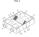
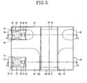
- Figs 4 and 5 are a perspective view and a plan view illustrating a ventilator in accordance with a first embodiment of the present invention
- Figs. 6 and 7 are cross-sectional views taken a long lines A-A a nd B-B of Fig. 5
- Fig. 8 is a perspective view illustrating disassembly of an air blowing means of the ventilator in accordance with the present invention.
- the ventilator of the first embodiment includes a casing 50 having an indoor air suction hole 52 and an outdoor air discharge hole 54 connected to the indoor side by ducts on its one surface, and an indoor air discharge hole 56 and an outdoor air suction hole 58 connected to the outdoor side by ducts on the facing surface to the surface where the indoor air suction hole 52 and the outdoor air discharge hole 54 have been formed, passages for flowing indoor air and passages for flowing outdoor air being formed inside the casing 50, a heat exchanger 60 installed to cross the center of the casing 50, for exchanging heat between indoor air and outdoor air, a first air blowing means 70 installed inside the indoor air discharge hole 56, for discharging indoor air or sucking outdoor air according to the rotation direction of a spiral fan 72, and a second air blowing means 80 installed inside the outdoor air suction hole 58, for discharging outdoor air or sucking indoor air according to the rotation direction of a spiral fan 82.
- the casing 50 is formed in the rectangular shape.
- the indoor air suction hole 52 and the outdoor air discharge hole 54 are formed on one surface of the casing 50 side by side, and the indoor air discharge hole 56 and the outdoor air suction hole 58 are formed on the facing surface of the casing 50 side by side.
- the heat exchanger 60 is installed to cross the casing 50, and level with one surface of the casing 50 where the indoor air suction hole 52 and the outdoor air discharge hole 54 have been formed.
- the indoor air suction hole 52 and the outdoor air suction hole 58 can be formed on one surface of the casing 50, and the outdoor air discharge hole 54 and the indoor air discharge hole 56 can be formed on the facing surface thereof.
- the heat exchanger 60 is installed by stacking first and second heat exchange units 62 and 64 to form first and second passages for separately flowing indoor air and outdoor air.
- the first and second heat exchange units 62 and 64 are formed by installing a plurality of guide ribs 60b on one side surfaces of rectangular or hexagonal thin heat exchange films 60a.
- the first and second passages for guiding indoor air or outdoor air are determined according to installation directions of the guide ribs 60b.
- a checking hole 50h is formed on one side surface of the casing 50, namely one side surface vertical to one surface of the casing where the indoor air suction hole 52 and the outdoor air discharge hole 54 have been formed to connect or disconnect the heat exchanger 60, and a checking cover 51 is installed to be opened or closed on the checking hole 50h.
- Guide grooves 55 are formed long in the width direction on the top and bottom surfaces of the casing 50 inside the checking hole 50h, so that the top and bottom ends of the heat exchanger 60 can be slidably inserted into the guide grooves 55. Accordingly, the heat exchanger 60 can be slidably connected or disconnected to/from the casing 50.
- the ventilator further includes an indoor air passage guide 92 installed in one side of the casing 50 where the indoor air suction hole 52 and the outdoor air discharge hole 54 have been formed from the heat exchanger 60, for guiding indoor air sucked from the indoor air suction hole 52 to the bottom of one side surface of the heat exchanger 60, and an outdoor air passage guide 94 installed in the other side of the casing 50 where the indoor air discharge hole 56 and the outdoor air suction hole 58 have been formed from the heat exchanger 60, for guiding outdoor air sucked from the outdoor air suction hole 58 to the bottom of the other side surface of the heat exchanger 60.
- the indoor air passage guide 92 is upwardly protruded to guide indoor air sucked from the indoor air suction hole 52 to the bottom of one side surface of the heat exchanger 60, and downwardly protruded to guide outdoor air discharged to the top of one side surface of the heat exchanger 60 to the outdoor air discharge hole 54.
- a guide groove 68a is formed long in the length direction in the end of the indoor air passage guide 92, so that a guide protrusion 66a formed long in the length direction on one side surface of the heat exchanger 60 can be slidably inserted into the guide groove 68a.
- the outdoor air passage guide 94 is upwardly protruded to guide outdoor air sucked from the outdoor air suction hole 58 to the bottom of the other s ide surface of the heat exchanger 60, and downwardly protruded to guide indoor air discharged to the top of the other side surface of the heat exchanger 60 to the indoor air discharge hole 56.
- a guide groove 68b is formed long in the length direction in the end of the outdoor a ir passage guide 94, so that a guide protrusion 66b formed long in the length direction on the other side surface of the heat exchanger 60 can be slidably inserted into the guide groove 68b.
- a filter 95 for filtering alien substances such as dust of outdoor air guided by the outdoor air passage guide 94 is installed in the end of the outdoor air passage guide 94.
- the filter 95 is positioned over the whole bottom of the other side surface of the heat exchanger 60.
- the first air blowing means 70 is installed inside the indoor air discharge hole 56, discharges indoor air when the built-in spiral fan 72 is rotated in the forward direction, and sucks outdoor air when the spiral fan 72 is rotated in the backward direction
- the second air blowing means 80 is installed inside the outdoor a ir suction hole 58, sucks outdoor air when the built-in spiral fan 82 is rotated in the forward direction, and discharges indoor air when the spiral fan 82 is rotated in the backward direction.
- the first air blowing means 70 can be installed inside the indoor air suction hole 52, and the second air blowing means 80 can be installed inside the outdoor air discharge hole 54.
- the indoor air suction hole 52 and the outdoor air discharge hole 54 a re connected to indoor side ducts, and thus vibrations a nd noises generated in the first and second air blowing means 70 and 80 are easily transmitted thereto.
- the first and second air blowing means 70 and 80 are installed inside the indoor air discharge hole 56 and the outdoor air suction hole 58.
- the spiral fan 72 of the first air blowing means 70 is rotated in the backward direction, and the spiral fan 82 of the second air blowing means 80 is rotated in the forward direction, to suck outdoor air from the indoor air discharge hole 56 and the outdoor air suction hole 58, and when an indoor air discharge amount must increase according to the using environment, the spiral fan 72 of the first air blowing means 70 is rotated in the forward direction, and the spiral fan 82 of the second air blowing means 80 is rotated in the backward direction, to discharge indoor air to the indoor air suction hole 52 and the outdoor air discharge hole 56.
- the spiral fan 72 of the first air blowing means 70 and the spiral fan 82 of the second air blowing means 80 can be rotated in the forward direction, to discharge indoor air and suck outdoor air at the same time.
- the spiral fan 72 of the first air blowing means 70 and the spiral fan 82 of the second air blowing means 80 can be rotated in the backward direction, to suck outdoor air and discharge indoor air at the same time.
- a first bypass damper 96 is installed between one end of the heat exchanger 60 and the casing 50 to open or close the passages, so that indoor air sucked from the indoor air suction hole 52 can be discharged to the indoor air discharge hole 56 not via the heat exchanger 60.
- the open/close status of the first bypass damper 96 is controlled.
- a second bypass damper 98 is installed between the other end of the heat exchanger 60 and the casing 50 to open or close the passages, so that indoor air sucked from the outdoor air discharge hole 54 can be discharged to the outdoor air suction hole 58 not via the heat exchanger 60.
- the open/close status of the second bypass damper 98 is controlled.
- the first and second air blowing means 70 and 80 include spiral fans 72 and 82 for forcibly sucking air and discharging sucked air in the axial direction, motors 74 and 84 for driving the spiral fans 72 and 82 in the forward or backward direction, fan housings 76 and 86 installed separately from the circumferences of the spiral fans 72 and 82, for guiding air flow, and supporting members 77, 78, 87.and 88 for rotatably fixing the spiral fans 72 and 82 and the motors 74 and 84 to the indoor air discharge hole 56 or the outdoor air suction hole 58 of the casing 50.
- the spiral fan 72 which is also called Yin-Yang fan includes a rotation axis 721' vertically coupled to the motor 74 and rotated, a long cylindrical hub 722 fixedly coupled to the rotation axis 721, and a pair of blades 723 spirally twisted in the axial direction from the front end to the rear end of the hub 722 on the outer circumference of the hub 722.
- Each of the blades 723 has a constant width from the front end to the rear end of the hub 722.
- the two blades 723 are formed in the facing positions, namely 180° separated positions, but more blades can be formed at regular intervals.
- the angle of twisting the blades 723 from the front end to the rear end of the hub 722 is not limited, but the spiral fan 72 is formed at an angle equal to or smaller than 180° in the axial direction of the hub 722 to prevent overlapping.
- the motor 74 is connected to the rotation axis 721 positioned in the bottom side of the hub 722, for rotating the spiral fan 72 in the forward or backward direction.
- the motor 74 is inserted into the hub 722, to reduce the whole fan size and flow resistance.
- the fan housing 76 is formed in the cylindrical shape having its top and bottom ends opened, and installed outside the spiral fan 72 to surround the spiral fan 72. When air is blown by rotation of the spiral fan 72, the fan housing 76 is operated as a path for increasing a constant pressure and maintaining constant air flow.
- the fan housing 76 can be incorporated or divided into a first fan housing 761 and a second fan housing 762 symmetric from the rotation axis 721.
- the middle parts 761 a and 762a are formed approximately in the straight line shape, and the front end and the rear end for sucking and discharging air compose extended units 761 b and 762b gradually externally extended.
- Each of the extended units 761 b and 762b is curved in a predetermined curvature.
- the first and second fan housings 761 and 762 have higher radius of curvature in the inlet sides for sucking air than the outlet sides for discharging air.
- Fixing members 75 can be installed to fix the first and second fan housings 761 and 762 to the casing 50.
- the supporting member includes a first supporting member 77 for rotatably supporting the rotation axis 721 protruded from the front end of the spiral fan 72, and a second supporting member 78 for supporting the motor 74 in the rear end of the spiral fan 72.
- the first supporting member 77 is comprised of a bearing unit 771 for rotatably supporting the front end of the rotation axis 721, four supporting bars 772a ⁇ 772d externally extended from both sides of the bearing unit 7 71, a first fixing bracket 773a formed to connect the outside ends of the two supporting bars 772a and 772b in one side, and fixed to the inner wall of the casing 50, and a second fixing bracket 773b formed to connect the outside ends of the two supporting bars 772c and 772d in the facing side to the first fixing bracket 773a, and fixed to the inner wall of the casing 50.
- the bearing unit 771, the two supporting bars 772a and 772b or 772c and 772d, and the fixing bracket 773a or 773b for connecting the supporting bars form a triangle when seen from the front or rear end.
- bearings (not shown) can be installed in the bearing unit 771, or the bearing unit 771 can be made of a magnetic lubricating material of high lubrication.
- each supporting bar 772a ⁇ 772d of the first supporting member 77 is upwardly inclined from the bearing unit 771 to the outside, to reduce noises when air is discharged through the spiral fan 72.
- the first and second fixing brackets 773a and 773b of the first supporting member 77 can be directly fixed to the inner walls of the casing 50 by using fastening means such as bolts and nuts, or the first supporting member 77 can be fixed to the inner walls of the casing 50 by using special supporting members 75.
- the second supporting member 78 includes a motor mounting unit 781 having a concave motor fixing groove 782 in its center so that the rear end of the motor 74 can be inserted into the groove 782, four supporting bars 784a ⁇ 784d extended from both ends of the motor mounting unit 781 as in the first supporting member 77, and first and second fixing brackets 785a and 785b for respectively connecting the outside ends of the supporting bars 784a ⁇ 784d.
- the motor mounting unit 781, the two supporting bars 784a and 784b or 784c and 784d and the fixing bracket 785a or 785b of the second supporting member 78 form a triangle when seen from the front or rear end.
- a vibration adsorbing packing member 783 which is made of flexible resin or synthetic resin and which the rear end of the motor 74 is inserted into is installed on the inner circumference of the motor fixing groove 782 in order to reduce vibrations when the motor 74 is driven.
- the second air blowing means 80 is formed in the same manner as the first air blowing means 70.
- air sucked from the indoor air discharge hole 56 and the outdoor air suction hole 58 is filtered by the filter 95 to remove alien substances such as dust, and sucked to the indoor side.
- Figs. 9 and 10 are a perspective view and a plan view illustrating a ventilator in accordance with a second embodiment of the present invention, and Figs. 11 and 12 are cross-sectional views taken along lines C-C and D-D of Fig. 10.
- an indoor air suction hole 152 and an outdoor air discharge hole 154 connected to the indoor side by ducts are formed on one surface of a rectangular casing 150
- an indoor air discharge hole 156 and an outdoor air suction hole 158 connected to the outdoor side by ducts are formed on the facing surface of the casing 150
- a heat exchanger 160 for forming passages for separately flowing outdoor air and indoor air in the casing 150, and exchanging heat between outdoor air and indoor air is installed vertically to one surface of the casing 150 where the indoor air suction hole 152 and the outdoor air discharge hole 154 have been formed.
- a checking hole 150h is formed on the bottom surface of the casing 150 to connect or disconnect the heat exchanger 160, and a checking cover 151 is installed to be connected or disconnected to/from the checking hole 150h.
- a first air blowing means 170 for discharging indoor air or sucking outdoor air is formed inside the indoor air discharge hole 156, and a second air blowing means 180 for sucking outdoor air or discharging indoor air is formed inside the outdoor air suction hole 158.
- a partition 161 is formed between the first and second air blowing means 170 and 180 to partition outdoor air or indoor air.
- An indoor air passage guide 192 for guiding indoor air or outdoor air to first passages of the heat exchanger 160 is installed in one side of the casing 150 where the indoor air suction hole 152 has been formed from the heat exchanger 160, and an outdoor air passage guide 194 for guiding indoor air or outdoor air to second passages of the heat exchanger 160 is installed in the other side of the casing 150 where the outdoor air discharge hole 154 has been formed.
- a filter (not shown) for filtering dust of outdoor air is installed between the end of the outdoor air passage guide 194 and the second passages of the heat exchanger 160.
- the heat exchanger 160 is installed by stacking first and second heat exchange units 162 and 164 for separately flowing indoor air and outdoor air.
- the first and second heat exchange units 162 and 164 are formed by installing a plurality of guide ribs 160b on one side surfaces of rectangular or hexagonal thin heat exchange films 160a.
- the first and second heat exchange units 162 and 164 are distinguished according to installation directions of the guide ribs 160b.
- sealing guide protrusions 166a and 166b are formed long in the length direction in both ends of the heat exchanger 160, and sealing elastic members 167a and 167b which the sealing guide protrusions 166a and 166b are closely adhered to are installed in the ends of the indoor air passage guide 192 and the outdoor air passage guide 194 to partition indoor air or outdoor air.
- Guide protrusions 168a and 168b are formed long in the height direction in the front and rear ends of the heat exchanger 160, and guide grooves 169a and 169b are formed long in the height direction on one surface of the casing 150 between the indoor air suction hole 152 and the outdoor air discharge hole 154 and on the partition 161 installed between the first and second air blowing means 170 and 180, so that the guide protrusions 168a and 168b can be slidably inserted into the guide grooves 169a and 169b.
- the guide protrusions 168a and 168b of the heat exchanger 160 are slidably inserted into the guide grooves 169a and 169b, and when the heat exchanger 160 is completely inserted into the casing 150, the sealing guide protrusions 166a and 166b of the heat exchanger 160 are closely adhered to the sealing elastic members 167a and 167b.
- the heat exchanger 160 can be fixed by using a special fixing means, or supported by fixing the checking cover 151 to the checking hole 150h.
- the first and second air blowing means 170 and 180 are fixed in fan housings 175 and 185, and include spiral fans 172 and 182 for sucking and discharging air in the axial direction, a pair of blades being spirally installed on the outer circumferences of hubs, motors 174 and 184 for driving the spiral fans 172 and 182 in the forward or reverse direction, and first and second supporting members 177, 178, 187 and 188 for respectively fixing the front ends of the spiral fans 172 and 182 and the rear ends of the motors 174 and 184 to the fan housings 175 and 185 or the inside of the casing 150. That is, the first and second air blowing means 170 and 180 are formed as described in the first embodiment of the invention.
- the ventilator of the second embodiment is operated in the same manner as the ventilator of the first embodiment.
- the spiral fan 172 of the first air blowing means 170 is rotated in the forward direction and the spiral fan 182 of the second air blowing means 180 is rotated in the forward direction, indoor air sucked from the indoor air suction hole 152 and outdoor air sucked from the outdoor air suction hole 158 exchange heat through the heat exchanger 160, and are discharged to the indoor air discharge hole 156 and the outdoor air discharge hole 154, respectively.
- outdoor air sucked from the outdoor air suction hole 158 is filtered by the filter to remove alien substances such as dust, and sucked to the heat exchanger 160.
- air sucked from the indoor air discharge hole 156 and the outdoor air suction hole 158 is filtered by the filter to remove alien substances such as dust, and sucked to the indoor side.
- Alien substances such as dust filtered by the filter are automatically discharged with indoor air to the indoor air discharge hole 156 and the outdoor air suction hole 158. Therefore, the user does not have to clean the filter.
Landscapes
- Engineering & Computer Science (AREA)
- Chemical & Material Sciences (AREA)
- Combustion & Propulsion (AREA)
- Mechanical Engineering (AREA)
- General Engineering & Computer Science (AREA)
- Physics & Mathematics (AREA)
- Thermal Sciences (AREA)
- Air-Conditioning Room Units, And Self-Contained Units In General (AREA)
- Duct Arrangements (AREA)
- Ventilation (AREA)
Abstract
Description
- The present invention relates to a ventilator for ventilating an indoor space by externally discharging indoor air and internally sucking outdoor air.
- In general, the carbon dioxide content of a ir increases in a hermetically sealed space with the passage of time because of breathing of living objects, and has detrimental effects on breathing. Accordingly, a ventilator is used to exchange contaminated indoor air for fresh outdoor air especially in a narrow space where a number of people stay such as an office or vehicle.
- The ventilator includes an air blower for forcibly blowing indoor air and outdoor air, and repeats a process of externally discharging contaminated indoor air and internally sucking fresh outdoor air.
- However, when cooling and ventilating operations are performed indoors at the same time, cooled indoor air is exhausted and hot outdoor air is sucked. Thus, a temperature of indoor air is higher than a cooling temperature, to reduce cooling efficiency. In the case that heating and ventilating operations are simultaneously performed indoors, heated indoor air is exhausted and cooled outdoor air is sucked. As a result, the temperature of indoor air is lower than a heating temperature, to reduce heating efficiency.
- Therefore, the ventilator further includes a heat exchanger for exchanging heat between indoor air and outdoor air.
- In detail, according to
Japanese Laid-Open Patent Application 11-287492 air suction hole 4 a for sucking outdoor a ir and an indoorair discharge hole 6b for discharging indoor air are formed on one surface of arectangular casing 2, an outdoorair discharge hole 4b for discharging outdoor air and an indoorair suction hole 6a for sucking indoor air are formed on the other surface of thecasing 2, aheat exchanger 8 for forming passages for separately flowing indoor air and outdoor air, and exchanging heat is installed in the center of thecasing 2 to cross thecasing 2, and anair supply fan 10 and anair exhaust fan 20 are installed in both edges of thecasing 2 to be positioned inside the outdoorair discharge hole 4b and the indoorair discharge hole 6b. - In addition, an air path for guiding outdoor air sucked from the outdoor
air suction hole 4a to theheat exchanger 8 to be discharged to the outdoorair discharge hole 4b, and an air path for guiding indoor air sucked from the indoorair suction hole 6a to theheat exchanger 8 to be discharged to the indoorair discharge hole 6b are formed in thecasing 2. - Here, the
heat exchanger 8 is installed to be connected or disconnected through a checking hole 2a formed in the center of one surface of thecasing 2. - On the other hand, as disclosed in
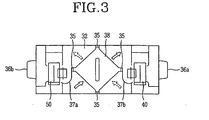
Japanese Laid-Open Patent Application 09-137984 air suction hole 34a for sucking outdoor air and an indoor air discharge hole 3 6b for discharging indoor air are formed on one surface of arectangular casing 32, an outdoorair discharge hole 34b for discharging outdoor air and an indoorair suction hole 36a for sucking indoor air are formed on the other surface of thecasing 32, aheat exchanger 38 for forming passages for separately flowing outdoor air and indoor air is installed in the center of thecasing 32 to cross thecasing 32, and anair supply fan 40 for sucking outdoor air and an air exhaust fan 45 for discharging indoor air are installed in the center of one surface of thecasing 32 and the center of the other surface of thecasing 32, respectively. - In addition, partitioning
units air suction hole 34a to theheat exchanger 38, or guiding indoor air sucked from the indoorair suction hole 36a to theheat exchanger 38 are installed in thecasing 32, andducts heat exchanger 38 to be discharged to the outdoorair discharge hole 34b, or guiding indoor air passing through theheat exchanger 38 to be discharged to the indoorair discharge hole 36b are installed in thecasing 32, to form air paths for separately flowing outdoor air and indoor air. - The h eat
exchanger 38 is installed in thecasing 32 to be connected or disconnected through a checking hole 32a formed in the center of one surface of thecasing 32. The edges of theheat exchanger 38 are slidably fixed intorails 35 formed in both ends of thepartitioning units casing 32. - However, in the conventional ventilator, when the air supply fan is operated, outdoor air is sucked through the passages formed between the outdoor air suction hole and the outdoor air discharge hole, and when the air exhaust fan is operated, indoor air is discharged through the passages formed between the indoor air suction hole and the indoor air discharge hole. Accordingly, an outdoor air suction amount and an indoor air discharge amount are controlled merely by the rotation speed of the air supply fan and the air exhaust fan, and thus limited.
- Moreover, a filter is built in the ventilator to filter alien substances of outdoor air such as dust before outdoor air is sucked to the heat exchanger. However, the ventilator is installed on a ceiling or inner wall of a building, and thus the filter is not cleaned.
- Furthermore, when the filter is covered with alien substances such as dust, suction flow of outdoor air decreases. As a result, air flow efficiency and heat exchange efficiency are reduced.
- An object of the present invention is to provide a ventilator which can appropriately control an outdoor air suction amount or indoor air discharge amount on the basis of the indoor environment, and maximize the outdoor air suction amount or indoor air discharge amount.
- Another object of the present invention is to provide a ventilator which can consult users' convenience and improve air flow efficiency and heat exchange efficiency, by automatically discharging alien substances of outdoor air such as dust.
- In order to achieve the above-described objects of the invention, there is provided a ventilator including: a casing having an indoor air suction hole and an outdoor air discharge hole connected to the indoor side, and an indoor air discharge hole and an outdoor air suction hole connected to the outdoor side; a heat exchanger installed in the casing, for forming first and second passages for separately flowing indoor air and outdoor air, and exchanging heat between indoor air and outdoor air; a first air blowing means installed on passages formed between the indoor air suction hole and the indoor air discharge hole, for discharging indoor air or alternatively sucking outdoor air according to the rotation direction; and a second air blowing means installed on passages formed between the outdoor air suction hole and the outdoor air discharge hole, for sucking outdoor air or alternatively discharging indoor air according to the rotation direction.
- According to one aspect of the invention, each of the first and second air blowing means includes a spiral fan rotated in the forward or alternatively backward direction, for forcibly flowing air in the axial direction or facing direction.
- Here, the first air blowing means is installed inside the indoor air discharge hole, and the second air blowing means is installed inside the outdoor air suction hole.
- According to another aspect of the invention, the spiral fan includes a cylindrical hub, and spiral blades being spirally twisted from one end to the other end of the hub on the outer circumference of the hub, and having a predetermined width in the axial direction.
- According to yet another aspect of the invention, each of the first and second air blowing means further includes a motor which a rotation axis protruded from the rear end of the spiral fan is coupled to, the motor rotating the rotation axis in the forward or backward direction, and at least one fan supporting member for supporting the spiral fan and the motor in the casing.
- The fan supporting member includes a first supporting member for rotatably supporting the front end of the rotation axis protruded from the front end of the spiral fan, and a second supporting member for supporting the motor in the rear end of the spiral fan. The first supporting member includes a bearing unit which the front end of the rotation axis is rotatably coupled to, a plurality of supporting bars externally extended from the bearing unit, and fixing units fixedly formed in the outside ends of the supporting bars, and fixed to the inner walls of the casing, and the second supporting member includes a motor mounting unit which the rear end of the motor is fixed to, a plurality of supporting bars externally extended from the motor mounting unit, and fixing units fixedly formed in the outside ends of the supporting bars, and fixed to the inner walls of the casing.
- According to yet another aspect of the invention, each of the first and second air blowing means further includes a fan housing installed to surround the blades of the spiral fan, for guiding air flow.
- Here, extended units having their diameter increased from the middle part to the front end and the rear end of the fan housing are formed in the fan housing, the middle part of the fan housing between the extended units is formed in the straight line shape, and the fan housing is symmetrically divided into first and second fan housings from the spiral fan.
- According to yet another aspect of the invention, the front end of the motor is inserted into the hub of the spiral fan to restrict air flow resistance and reduce an installation space.
- According to yet another aspect of the invention, a checking hole is formed on the casing so that the heat exchanger can be connected or disconnected to/from the casing.
- The heat exchanger is installed in the casing to be level with one surface of the casing where the indoor air suction hole and the outdoor air discharge hole have been formed, and the checking hole is formed on one side surface of the casing vertical to one surface where the indoor air suction hole and the outdoor air discharge hole have been formed.
- The ventilator further includes an indoor air passage guide installed in one side of the casing where the indoor air suction hole has been formed from the heat exchanger, for guiding indoor air or outdoor air along the first passages of the heat exchanger, and an outdoor air passage guide installed in the other side of the casing where the outdoor air suction hole has been formed from the heat exchanger, for guiding indoor air or outdoor air along the second passages of the heat exchanger. Guide protrusions are formed long in the length direction in both ends of the heat exchanger, and guide grooves are formed long in the length direction in the ends of the indoor air passage guide and the outdoor air passage guide, so that the guide protrusions of the heat exchanger can be slidably inserted into the guide grooves.
- Here, the ventilator further includes a filter installed between the end of the outdoor air passage guide and the second passages of the heat exchanger, for filtering dust of outdoor air.
- According to yet another aspect of the invention, a first bypass damper for opening the passages between the indoor air suction hole and the indoor air discharge hole is installed to be opened or closed between the heat exchanger and the casing. When the spiral fan of the first air blowing means is rotated to suck indoor air, the open/close status of the first bypass damper is controlled.
- According to yet another aspect of the invention, a second bypass damper for opening the passages between the outdoor air suction hole and the outdoor air discharge hole is installed to be opened or closed between the heat exchanger and the casing. When the spiral fan of the second air blowing means is rotated to suck indoor air, the open/close status of the second bypass damper is controlled.
- On the other hand, the heat exchanger is installed vertically to one surface of the casing where the indoor air suction hole and the outdoor air discharge hole have been formed, and the checking hole is formed on the bottom surface of the casing.
- The ventilator further includes an indoor air passage guide installed in one side of the casing where the indoor air suction hole has been formed from the heat exchanger, for guiding indoor air or outdoor air along the first passages of the heat exchanger, a nd an outdoor a ir passage guide installed in the other side of the casing where the outdoor air discharge hole has been formed from the heat exchanger, for guiding indoor air or outdoor air along the second passages of the heat exchanger.
- Here, guide protrusions are formed long in the height direction in the front and rear ends of the heat exchanger, and guide grooves are formed long in the height direction on one surface of the casing between the indoor air suction hole and the outdoor air discharge hole and on a partition installed between the first and second air blowing means, so that the guide protrusions can be slidably inserted into the guide grooves. Sealing guide protrusions are formed long in the length direction in both ends of the heat exchanger to contact the indoor air passage guide and the outdoor air passage guide, and sealing elastic members protruded long in the length direction are fixed to the ends of the indoor air passage guide and the outdoor air passage guide, so that the sealing guide protrusions can be closely adhered to the sealing elastic members.
- The ventilator further includes a filter installed between the end of the outdoor air passage guide and the second passages of the heat exchanger, for filtering dust of outdoor air.
- The present invention will become better understood with reference to the accompanying drawings which are given only by way of illustration and thus are not limitative of the present invention, wherein:
- Fig. 1 is a perspective view illustrating one example of a conventional ventilator;
- Fig. 2 is a perspective view illustrating another example of the conventional ventilator;
- Fig. 3 is a cross-sectional view illustrating another example of the conventional ventilator;
- Fig. 4 is a perspective view illustrating a ventilator in accordance with a first embodiment of the present invention;
- Fig. 5 is a plan view illustrating the ventilator in accordance with the first embodiment of the present invention;
- Fig. 6 is a cross-sectional view taken along line A-A of Fig. 5;
- Fig. 7 is a cross-sectional view taken along line B-B of Fig. 5;
- Fig. 8 is a perspective view illustrating disassembly of an air blowing means of the ventilator in accordance with the present invention;
- Fig. 9 is a perspective view illustrating a ventilator in accordance with a second embodiment of the present invention;
- Fig. 10 is a plan view illustrating the ventilator in accordance with the second embodiment of the present invention;
- Fig. 11 is a cross-sectional view taken along line C-C of Fig. 10; and
- Fig. 12 is a cross-sectional view taken along line D-D of Fig. 10.
- Preferred embodiments of the present invention will now be described in detail with reference to the accompanying drawings.
- Figs 4 and 5 are a perspective view and a plan view illustrating a ventilator in accordance with a first embodiment of the present invention, Figs. 6 and 7 are cross-sectional views taken a long lines A-A a nd B-B of Fig. 5, and Fig. 8 is a perspective view illustrating disassembly of an air blowing means of the ventilator in accordance with the present invention.
- Referring to Figs. 4 to 7, the ventilator of the first embodiment includes a
casing 50 having an indoorair suction hole 52 and an outdoorair discharge hole 54 connected to the indoor side by ducts on its one surface, and an indoorair discharge hole 56 and an outdoorair suction hole 58 connected to the outdoor side by ducts on the facing surface to the surface where the indoorair suction hole 52 and the outdoorair discharge hole 54 have been formed, passages for flowing indoor air and passages for flowing outdoor air being formed inside thecasing 50, aheat exchanger 60 installed to cross the center of thecasing 50, for exchanging heat between indoor air and outdoor air, a first air blowing means 70 installed inside the indoorair discharge hole 56, for discharging indoor air or sucking outdoor air according to the rotation direction of aspiral fan 72, and a second air blowing means 80 installed inside the outdoorair suction hole 58, for discharging outdoor air or sucking indoor air according to the rotation direction of aspiral fan 82. - The
casing 50 is formed in the rectangular shape. The indoorair suction hole 52 and the outdoorair discharge hole 54 are formed on one surface of thecasing 50 side by side, and the indoorair discharge hole 56 and the outdoorair suction hole 58 are formed on the facing surface of thecasing 50 side by side. Theheat exchanger 60 is installed to cross thecasing 50, and level with one surface of thecasing 50 where the indoorair suction hole 52 and the outdoorair discharge hole 54 have been formed. - The indoor
air suction hole 52 and the outdoorair suction hole 58 can be formed on one surface of thecasing 50, and the outdoorair discharge hole 54 and the indoorair discharge hole 56 can be formed on the facing surface thereof. - Here, the
heat exchanger 60 is installed by stacking first and secondheat exchange units heat exchange units guide ribs 60b on one side surfaces of rectangular or hexagonal thinheat exchange films 60a. The first and second passages for guiding indoor air or outdoor air are determined according to installation directions of theguide ribs 60b. - A checking
hole 50h is formed on one side surface of thecasing 50, namely one side surface vertical to one surface of the casing where the indoorair suction hole 52 and the outdoorair discharge hole 54 have been formed to connect or disconnect theheat exchanger 60, and a checkingcover 51 is installed to be opened or closed on thechecking hole 50h.Guide grooves 55 are formed long in the width direction on the top and bottom surfaces of thecasing 50 inside the checkinghole 50h, so that the top and bottom ends of theheat exchanger 60 can be slidably inserted into theguide grooves 55. Accordingly, theheat exchanger 60 can be slidably connected or disconnected to/from thecasing 50. - The ventilator further includes an indoor
air passage guide 92 installed in one side of thecasing 50 where the indoorair suction hole 52 and the outdoorair discharge hole 54 have been formed from theheat exchanger 60, for guiding indoor air sucked from the indoorair suction hole 52 to the bottom of one side surface of theheat exchanger 60, and an outdoorair passage guide 94 installed in the other side of thecasing 50 where the indoorair discharge hole 56 and the outdoorair suction hole 58 have been formed from theheat exchanger 60, for guiding outdoor air sucked from the outdoorair suction hole 58 to the bottom of the other side surface of theheat exchanger 60. - The indoor
air passage guide 92 is upwardly protruded to guide indoor air sucked from the indoorair suction hole 52 to the bottom of one side surface of theheat exchanger 60, and downwardly protruded to guide outdoor air discharged to the top of one side surface of theheat exchanger 60 to the outdoorair discharge hole 54. Aguide groove 68a is formed long in the length direction in the end of the indoorair passage guide 92, so that aguide protrusion 66a formed long in the length direction on one side surface of theheat exchanger 60 can be slidably inserted into theguide groove 68a. - Identical to the indoor
air passage guide 92, the outdoorair passage guide 94 is upwardly protruded to guide outdoor air sucked from the outdoorair suction hole 58 to the bottom of the other s ide surface of theheat exchanger 60, and downwardly protruded to guide indoor air discharged to the top of the other side surface of theheat exchanger 60 to the indoorair discharge hole 56. Aguide groove 68b is formed long in the length direction in the end of the outdoor air passage guide 94, so that aguide protrusion 66b formed long in the length direction on the other side surface of theheat exchanger 60 can be slidably inserted into theguide groove 68b. - A
filter 95 for filtering alien substances such as dust of outdoor air guided by the outdoorair passage guide 94 is installed in the end of the outdoorair passage guide 94. Thefilter 95 is positioned over the whole bottom of the other side surface of theheat exchanger 60. - The first air blowing means 70 is installed inside the indoor
air discharge hole 56, discharges indoor air when the built-inspiral fan 72 is rotated in the forward direction, and sucks outdoor air when thespiral fan 72 is rotated in the backward direction, and the second air blowing means 80 is installed inside the outdoor air suction hole 58, sucks outdoor air when the built-inspiral fan 82 is rotated in the forward direction, and discharges indoor air when thespiral fan 82 is rotated in the backward direction. - The first air blowing means 70 can be installed inside the indoor
air suction hole 52, and the second air blowing means 80 can be installed inside the outdoorair discharge hole 54. However, the indoorair suction hole 52 and the outdoor air discharge hole 54 a re connected to indoor side ducts, and thus vibrations a nd noises generated in the first and second air blowing means 70 and 80 are easily transmitted thereto. Preferably, the first and second air blowing means 70 and 80 are installed inside the indoorair discharge hole 56 and the outdoorair suction hole 58. - Therefore, when an outdoor air suction amount must increase according to the using environment, the
spiral fan 72 of the first air blowing means 70 is rotated in the backward direction, and thespiral fan 82 of the second air blowing means 80 is rotated in the forward direction, to suck outdoor air from the indoorair discharge hole 56 and the outdoorair suction hole 58, and when an indoor air discharge amount must increase according to the using environment, thespiral fan 72 of the first air blowing means 70 is rotated in the forward direction, and thespiral fan 82 of the second air blowing means 80 is rotated in the backward direction, to discharge indoor air to the indoorair suction hole 52 and the outdoorair discharge hole 56. - The
spiral fan 72 of the first air blowing means 70 and thespiral fan 82 of the second air blowing means 80 can be rotated in the forward direction, to discharge indoor air and suck outdoor air at the same time. In addition, thespiral fan 72 of the first air blowing means 70 and thespiral fan 82 of the second air blowing means 80 can be rotated in the backward direction, to suck outdoor air and discharge indoor air at the same time. - In the case that the
spiral fan 72 of the first air blowing means 70 is rotated in the forward direction to discharge indoor air, afirst bypass damper 96 is installed between one end of theheat exchanger 60 and thecasing 50 to open or close the passages, so that indoor air sucked from the indoorair suction hole 52 can be discharged to the indoorair discharge hole 56 not via theheat exchanger 60. When thespiral fan 72 of the first air blowing means 70 is operated to suck indoor air, the open/close status of thefirst bypass damper 96 is controlled. - When the
spiral fan 82 of the second air blowing means 80 is rotated in the backward direction to discharge indoor air, asecond bypass damper 98 is installed between the other end of theheat exchanger 60 and thecasing 50 to open or close the passages, so that indoor air sucked from the outdoorair discharge hole 54 can be discharged to the outdoorair suction hole 58 not via theheat exchanger 60. When thespiral fan 82 of the second air blowing means 80 is operated to suck indoor air, the open/close status of thesecond bypass damper 98 is controlled. - On the other hand, the first and second air blowing means 70 and 80 include
spiral fans motors spiral fans fan housings spiral fans members spiral fans motors air discharge hole 56 or the outdoorair suction hole 58 of thecasing 50. - The structure of the first air blowing means 70 w ill now be explained i n detail with reference to Fig. 8. The
spiral fan 72 which is also called Yin-Yang fan includes a rotation axis 721' vertically coupled to themotor 74 and rotated, a long cylindrical hub 722 fixedly coupled to therotation axis 721, and a pair ofblades 723 spirally twisted in the axial direction from the front end to the rear end of the hub 722 on the outer circumference of the hub 722. Each of theblades 723 has a constant width from the front end to the rear end of the hub 722. - Here, the two
blades 723 are formed in the facing positions, namely 180° separated positions, but more blades can be formed at regular intervals. - In addition, the angle of twisting the
blades 723 from the front end to the rear end of the hub 722 is not limited, but thespiral fan 72 is formed at an angle equal to or smaller than 180° in the axial direction of the hub 722 to prevent overlapping. - Because the
blades 723 of thespiral fan 72 are spirally twisted in the vertical axial direction, when thespiral fan 72 is rotated in the forward direction, air passes through thespiral fan 72 in the axial direction along the surfaces of theblades 723, and when thespiral fan 72 is rotated in the backward direction, air passes through thespiral fan 72 in the facing direction. Here, air flow and air pressure are almost identical in the same external conditions. - The
motor 74 is connected to therotation axis 721 positioned in the bottom side of the hub 722, for rotating thespiral fan 72 in the forward or backward direction. Here, themotor 74 is inserted into the hub 722, to reduce the whole fan size and flow resistance. - The
fan housing 76 is formed in the cylindrical shape having its top and bottom ends opened, and installed outside thespiral fan 72 to surround thespiral fan 72. When air is blown by rotation of thespiral fan 72, thefan housing 76 is operated as a path for increasing a constant pressure and maintaining constant air flow. - The
fan housing 76 can be incorporated or divided into afirst fan housing 761 and asecond fan housing 762 symmetric from therotation axis 721. - In the first and
second fan housings middle parts extended units extended units second fan housings - Each edge of the front end and the rear end of the first and
second fan housings casing 50. Fixingmembers 75 can be installed to fix the first andsecond fan housings casing 50. - The supporting member includes a first supporting
member 77 for rotatably supporting therotation axis 721 protruded from the front end of thespiral fan 72, and a second supportingmember 78 for supporting themotor 74 in the rear end of thespiral fan 72. - Here, the first supporting
member 77 is comprised of abearing unit 771 for rotatably supporting the front end of therotation axis 721, four supportingbars 772a~772d externally extended from both sides of the bearing unit 7 71, afirst fixing bracket 773a formed to connect the outside ends of the two supportingbars casing 50, and asecond fixing bracket 773b formed to connect the outside ends of the two supportingbars first fixing bracket 773a, and fixed to the inner wall of thecasing 50. Thebearing unit 771, the two supportingbars bracket - In order to smoothly rotate the
spiral fan 72, bearings (not shown) can be installed in thebearing unit 771, or thebearing unit 771 can be made of a magnetic lubricating material of high lubrication. - Preferably, each supporting
bar 772a~772d of the first supportingmember 77 is upwardly inclined from thebearing unit 771 to the outside, to reduce noises when air is discharged through thespiral fan 72. - That is, when air from the
spiral fan 72 passes through the supportingbars 772a~772d of the upper supportingmember 77, vortexes are generated. Such vortexes generate frequencies. If the supportingbars 772a~772d are formed in the same height, the same frequencies are generated by the vortexes in every point of the supportingbars 772a~772d, which amplifies noises. - However, as described above, when the supporting
bars 772a~772d are inclined, different frequencies are generated by the vortexes in each point of the supportingbars 772a-772d, thereby reducing noises. - The first and
second fixing brackets member 77 can be directly fixed to the inner walls of thecasing 50 by using fastening means such as bolts and nuts, or the first supportingmember 77 can be fixed to the inner walls of thecasing 50 by using special supportingmembers 75. - The second supporting
member 78 includes amotor mounting unit 781 having a concavemotor fixing groove 782 in its center so that the rear end of themotor 74 can be inserted into thegroove 782, four supporting bars 784a~784d extended from both ends of themotor mounting unit 781 as in the first supportingmember 77, and first andsecond fixing brackets - Identically to the first supporting
member 77, themotor mounting unit 781, the two supportingbars bracket member 78 form a triangle when seen from the front or rear end. - Preferably, a vibration
adsorbing packing member 783 which is made of flexible resin or synthetic resin and which the rear end of themotor 74 is inserted into is installed on the inner circumference of themotor fixing groove 782 in order to reduce vibrations when themotor 74 is driven. - The second air blowing means 80 is formed in the same manner as the first air blowing means 70.
- Accordingly, when the spiral f an 7 2 of the first air blowing means 7 0 is rotated in the forward direction, indoor air sucked from the indoor
air suction hole 52 exchanges heat with outdoor air through theheat exchanger 60, and is discharged to the indoorair discharge hole 56, and when thespiral fan 82 of the second air blowing means 80 is rotated in the forward direction, outdoor air sucked from the outdoorair suction hole 58 is filtered by thefilter 95 to remove alien substances such as dust, exchanges heat with indoor air through theheat exchanger 60, and is discharged to the outdoorair discharge hole 54. - Here, when the
first bypass damper 96 is opened, indoor air sucked from the indoorair suction hole 52 can be discharged to the indoorair discharge hole 56 not via theheat exchanger 60. - On the other hand, when the
spiral fan 72 of the first air blowing means 70 is rotated in the backward direction and thespiral fan 82 of the second air blowing means 80 is rotated in the forward direction, outdoor air is sucked from the indoorair discharge hole 56 and the outdoorair suction hole 58 at the same time, and discharged to the indoorair suction hole 52 and the outdoorair discharge hole 54, to increase the outdoor air suction amount. - Here, air sucked from the indoor
air discharge hole 56 and the outdoorair suction hole 58 is filtered by thefilter 95 to remove alien substances such as dust, and sucked to the indoor side. - In addition, when the
spiral fan 72 of the first air blowing means 70 is rotated in the forward direction and thespiral fan 8 2 of the second a ir blowing means 80 is rotated in the backward direction, indoor air is sucked from the indoorair suction hole 52 and the outdoorair discharge hole 54 at the same time, and discharged to the indoorair discharge hole 56 and the outdoorair suction hole 58, to increase the indoor air discharge amount. - In the case that the
first bypass damper 96 and thesecond bypass damper 98 are simultaneously opened, indoor air sucked from the indoorair suction hole 52 and the outdoorair discharge hole 54 can be discharged to the indoorair discharge hole 56 and the outdoorair suction hole 58 not via theheat exchanger 60. - When the ventilator is operated, alien substances such as dust filtered by the
filter 95 are automatically discharged with indoor air to the indoorair discharge hole 56 and the outdoorair suction hole 58. Therefore, thefilter 95 needs not to be cleaned. - Figs. 9 and 10 are a perspective view and a plan view illustrating a ventilator in accordance with a second embodiment of the present invention, and Figs. 11 and 12 are cross-sectional views taken along lines C-C and D-D of Fig. 10.
- As illustrated in Figs. 9 to 12, in the ventilator of the second embodiment, an indoor
air suction hole 152 and an outdoorair discharge hole 154 connected to the indoor side by ducts are formed on one surface of arectangular casing 150, an indoorair discharge hole 156 and an outdoorair suction hole 158 connected to the outdoor side by ducts are formed on the facing surface of thecasing 150, and aheat exchanger 160 for forming passages for separately flowing outdoor air and indoor air in thecasing 150, and exchanging heat between outdoor air and indoor air is installed vertically to one surface of thecasing 150 where the indoorair suction hole 152 and the outdoorair discharge hole 154 have been formed. Achecking hole 150h is formed on the bottom surface of thecasing 150 to connect or disconnect theheat exchanger 160, and a checkingcover 151 is installed to be connected or disconnected to/from thechecking hole 150h. - A first air blowing means 170 for discharging indoor air or sucking outdoor air is formed inside the indoor
air discharge hole 156, and a second air blowing means 180 for sucking outdoor air or discharging indoor air is formed inside the outdoorair suction hole 158. Apartition 161 is formed between the first and second air blowing means 170 and 180 to partition outdoor air or indoor air. - An indoor
air passage guide 192 for guiding indoor air or outdoor air to first passages of theheat exchanger 160 is installed in one side of thecasing 150 where the indoorair suction hole 152 has been formed from theheat exchanger 160, and an outdoorair passage guide 194 for guiding indoor air or outdoor air to second passages of theheat exchanger 160 is installed in the other side of thecasing 150 where the outdoorair discharge hole 154 has been formed. A filter (not shown) for filtering dust of outdoor air is installed between the end of the outdoorair passage guide 194 and the second passages of theheat exchanger 160. - As described in the first embodiment of the present invention, the
heat exchanger 160 is installed by stacking first and secondheat exchange units heat exchange units guide ribs 160b on one side surfaces of rectangular or hexagonal thinheat exchange films 160a. The first and secondheat exchange units guide ribs 160b. - Especially, sealing
guide protrusions heat exchanger 160, and sealingelastic members guide protrusions air passage guide 192 and the outdoorair passage guide 194 to partition indoor air or outdoor air. -
Guide protrusions heat exchanger 160, and guidegrooves casing 150 between the indoorair suction hole 152 and the outdoorair discharge hole 154 and on thepartition 161 installed between the first and second air blowing means 170 and 180, so that theguide protrusions guide grooves - When the
heat exchanger 160 is installed in the upward direction through thechecking hole 150h formed on the bottom surface of thecasing 150, theguide protrusions heat exchanger 160 are slidably inserted into theguide grooves heat exchanger 160 is completely inserted into thecasing 150, the sealingguide protrusions heat exchanger 160 are closely adhered to the sealingelastic members heat exchanger 160 can be fixed by using a special fixing means, or supported by fixing the checkingcover 151 to thechecking hole 150h. - On the other hand, the first and second air blowing means 170 and 180 are fixed in
fan housings spiral fans motors spiral fans members spiral fans motors fan housings casing 150. That is, the first and second air blowing means 170 and 180 are formed as described in the first embodiment of the invention. - Accordingly, the ventilator of the second embodiment is operated in the same manner as the ventilator of the first embodiment. When the
spiral fan 172 of the first air blowing means 170 is rotated in the forward direction and thespiral fan 182 of the second air blowing means 180 is rotated in the forward direction, indoor air sucked from the indoorair suction hole 152 and outdoor air sucked from the outdoorair suction hole 158 exchange heat through theheat exchanger 160, and are discharged to the indoorair discharge hole 156 and the outdoorair discharge hole 154, respectively. - Here, outdoor air sucked from the outdoor
air suction hole 158 is filtered by the filter to remove alien substances such as dust, and sucked to theheat exchanger 160. - When the
spiral fan 172 of the first air blowing means 170 is rotated in the backward direction and thespiral fan 182 of the first air blowing means 180 is rotated in the forward direction, outdoor air is sucked from the indoorair discharge hole 156 and the outdoorair suction hole 158 at the same time, and discharged to the indoorair suction hole 152 and the outdoorair discharge hole 154, to increase the outdoor air suction amount. - Here, air sucked from the indoor
air discharge hole 156 and the outdoorair suction hole 158 is filtered by the filter to remove alien substances such as dust, and sucked to the indoor side. - In addition, when the
spiral fan 172 of the first air blowing means 170 is rotated-in the forward direction and thespiral fan 182 of the second air blowing means 180 is rotated in the backward direction, indoor air is sucked from the indoorair suction hole 152 and the outdoorair discharge hole 154 at the same time, and discharged to the indoorair discharge hole 156 and the outdoorair suction hole 158, to increase the indoor air discharge amount. - Alien substances such as dust filtered by the filter are automatically discharged with indoor air to the indoor
air discharge hole 156 and the outdoorair suction hole 158. Therefore, the user does not have to clean the filter. - The ventilator has been explained in detail on the basis of the embodiments and accompanying drawings of the present invention. However, it is understood that the present invention should not be limited to these preferred embodiments but various changes and modifications can be made by one skilled in the art within the scope of the present invention as hereinafter claimed.
Claims (30)
- A ventilator, comprising:a casing having an indoor air suction hole and an outdoor air discharge hole connected to the indoor side, and an indoor air discharge hole and an outdoor air suction hole connected to the outdoor side;a heat exchanger installed in the casing, for forming first and second passages for separately flowing indoor air and outdoor air, and exchanging heat between indoor air and outdoor air;a first air blowing means installed on passages formed between the indoor air suction hole and the indoor air discharge hole, for discharging indoor air or alternatively sucking outdoor air according to the rotation direction; anda second air blowing means installed on passages formed between the outdoor air suction hole and the outdoor air discharge hole, for sucking outdoor air or alternatively discharging indoor air according to the rotation direction.
- The ventilator of claim 1, wherein each of the first and second air blowing means comprises a spiral fan rotated in the forward or backward direction, for forcibly flowing air in the axial direction or alternatively facing direction.
- The ventilator of claim 2, wherein the first air blowing means is installed inside the indoor air discharge hole.
- The ventilator of claim 2, wherein the second air blowing means is installed inside the outdoor air suction hole.
- The ventilator of claim 2, wherein the spiral fan comprises a cylindrical hub, and spiral blades being spirally twisted from one end to the other end of the hub on the outer circumference of the hub, and having a predetermined width in the axial direction.
- The ventilator of claim 5, wherein each of the first and second air blowing means further comprises a motor which a rotation axis protruded from the rear end of the spiral fan is coupled to, the motor rotating the rotation axis in the forward or backward direction, and at least one fan supporting member for supporting the spiral fan and the motor in the casing.
- The ventilator of claim 6, wherein the fan supporting member comprises a first supporting member for rotatably supporting the front end of the rotation axis protruded from the front end of the spiral fan, and a second supporting member for supporting the motor in the rear end of the spiral fan.
- The ventilator of claim 7, wherein the first supporting member comprises a bearing unit which the front end of the rotation axis is rotatably coupled to, a plurality of supporting bars externally extended from the bearing unit, and fixing units fixedly formed in the outside ends of the supporting bars, and fixed to the inner walls of the casing.
- The ventilator of claim 7, wherein the second supporting member comprises a motor mounting unit which the rear end of the motor is fixed to, a plurality of supporting bars externally extended from the motor mounting unit, and fixing units fixedly formed in the outside ends of the supporting bars, and fixed to the inner walls of the casing.
- The ventilator of claim 6, wherein each of the first and second air blowing means further comprises a fan housing installed to surround the blades of the spiral fan, for guiding air flow.
- The ventilator of claim 10, wherein extended units having their diameter increased from the middle part to the front end and the rear end of the fan housing are formed in the fan housing.
- The ventilator of claim 11, wherein the middle part of the fan housing between the extended units is formed in the straight line shape.
- The ventilator of claim 10 or 11, wherein the fan housing is symmetrically divided into first and second fan housings from the spiral fan.
- The ventilator of claim 6, wherein the front end of the motor is inserted into the hub of the spiral fan.
- The ventilator of claim 2, wherein a checking hole is formed on the casing so that the heat exchanger can be connected or disconnected to/from the casing.
- The ventilator of claim 15, wherein the heat exchanger is installed in the casing to be level with one surface of the casing where the indoor air suction hole and the outdoor air discharge hole have been formed, and the checking hole is formed on one side surface of the casing vertical to one surface where the indoor air suction hole and the outdoor air discharge hole have been formed.
- The ventilator of claim 16, further comprising an indoor air passage guide installed in one side of the casing where the indoor air suction hole has been formed from the heat exchanger, for guiding indoor air or outdoor air along the first passages of the heat exchanger.
- The ventilator of claim 17, further comprising an outdoor air passage guide installed in the other side of the casing where the outdoor air suction hole has been formed from the heat exchanger, for guiding indoor air or outdoor air along the second passages of the heat exchanger.
- The ventilator of claim 18, wherein guide protrusions are formed long in the length direction in both ends of the heat exchanger, and guide grooves are formed long in the length direction in the ends of the indoor air passage guide and the outdoor air passage guide, so that the guide protrusions of the heat exchanger can be slidably inserted into the guide grooves.
- The ventilator of claim 18, further comprising a filter installed between the end of the outdoor air passage guide and the second passages of the heat exchanger, for filtering dust of outdoor air.
- The ventilator of claim 16, wherein a first bypass damper for opening the passages between the indoor air suction hole and the indoor air discharge hole is installed to be opened or closed between the heat exchanger and the casing.
- The ventilator of claim 21, wherein, when the spiral fan of the first air blowing means is rotated to suck indoor air, the open/close status of the first bypass damper is controlled.
- The ventilator of claim 16, wherein a second bypass damper for opening the passages between the outdoor air suction hole and the outdoor air discharge hole is installed to be opened or closed between the heat exchanger and the casing.
- The ventilator of claim 23, wherein, when the spiral fan of the second air blowing means is rotated to suck indoor air, the open/close status of the second bypass damper is controlled.
- The ventilator of claim 15, wherein the heat exchanger is installed vertically to one surface of the casing where the indoor air suction hole and the outdoor air discharge hole have been formed, and the checking hole is formed on the bottom surface of the casing.
- The ventilator of claim 25, further comprising an indoor air passage guide installed in one side of the casing where the indoor air suction hole has been formed from the heat exchanger, for guiding indoor air or outdoor air along the first passages of the heat exchanger.
- The ventilator of claim 26, further comprising an outdoor air passage guide installed in the other side of the casing where the outdoor air discharge hole has been formed from the heat exchanger, for guiding indoor air or outdoor air along the second passages of the heat exchanger.
- The ventilator of claim 27, wherein guide protrusions are formed long in the height direction in the front and rear ends of the heat exchanger, and guide grooves are formed long in the height direction on one surface of the casing between the indoor air suction hole and the outdoor air discharge hole and on a partition installed between the first and second air blowing means, so that the guide protrusions can be slidably inserted into the guide grooves.
- The ventilator of claim 28, wherein sealing guide protrusions are formed long in the length direction in both ends of the heat exchanger to contact the indoor air passage guide and the outdoor air passage guide, and sealing elastic members protruded long in the length direction are fixed to the ends of the indoor air passage guide and the outdoor air passage guide, so that the sealing guide protrusions can be closely adhered to the sealing elastic members.
- The ventilator of claim 27, further comprising a filter installed between the end of the outdoor air passage guide and the second passages of the heat exchanger, for filtering dust of outdoor air.
Applications Claiming Priority (1)
| Application Number | Priority Date | Filing Date | Title |
|---|---|---|---|
| PCT/KR2003/002131 WO2005036069A1 (en) | 2003-10-14 | 2003-10-14 | Ventilator |
Publications (2)
| Publication Number | Publication Date |
|---|---|
| EP1680629A1 EP1680629A1 (en) | 2006-07-19 |
| EP1680629B1 true EP1680629B1 (en) | 2008-01-02 |
Family
ID=34431675
Family Applications (1)
| Application Number | Title | Priority Date | Filing Date |
|---|---|---|---|
| EP03751547A Expired - Lifetime EP1680629B1 (en) | 2003-10-14 | 2003-10-14 | Ventilator |
Country Status (5)
| Country | Link |
|---|---|
| EP (1) | EP1680629B1 (en) |
| AT (1) | ATE382832T1 (en) |
| AU (1) | AU2003269540A1 (en) |
| DE (1) | DE60318501D1 (en) |
| WO (1) | WO2005036069A1 (en) |
Families Citing this family (3)
| Publication number | Priority date | Publication date | Assignee | Title |
|---|---|---|---|---|
| JP5541043B2 (en) * | 2010-09-28 | 2014-07-09 | パナソニック株式会社 | Heat exchanger |
| CN102205331A (en) * | 2011-01-25 | 2011-10-05 | 北京博纳睿思环保科技有限公司 | Air exhaust purification dedusting workbench |
| US11435109B2 (en) | 2017-03-24 | 2022-09-06 | Mitsubishi Electric Corporation | Ventilator |
Family Cites Families (3)
| Publication number | Priority date | Publication date | Assignee | Title |
|---|---|---|---|---|
| JPS63210544A (en) * | 1987-02-27 | 1988-09-01 | Mitsubishi Electric Corp | Ventilator with heat exchanger |
| JP4390897B2 (en) * | 1999-03-04 | 2009-12-24 | 三菱電機株式会社 | Heat exchange ventilator |
| JP4656777B2 (en) * | 2001-08-31 | 2011-03-23 | 三菱電機株式会社 | Ventilation equipment |
-
2003
- 2003-10-14 AT AT03751547T patent/ATE382832T1/en not_active IP Right Cessation
- 2003-10-14 DE DE60318501T patent/DE60318501D1/en not_active Expired - Lifetime
- 2003-10-14 EP EP03751547A patent/EP1680629B1/en not_active Expired - Lifetime
- 2003-10-14 AU AU2003269540A patent/AU2003269540A1/en not_active Abandoned
- 2003-10-14 WO PCT/KR2003/002131 patent/WO2005036069A1/en not_active Ceased
Also Published As
| Publication number | Publication date |
|---|---|
| WO2005036069A1 (en) | 2005-04-21 |
| ATE382832T1 (en) | 2008-01-15 |
| DE60318501D1 (en) | 2008-02-14 |
| AU2003269540A1 (en) | 2005-04-27 |
| EP1680629A1 (en) | 2006-07-19 |
Similar Documents
| Publication | Publication Date | Title |
|---|---|---|
| EP0507107B1 (en) | Heat recovery ventilator | |
| CN1707170B (en) | Air conditioner | |
| US20050287945A1 (en) | Ventilating system | |
| US5775125A (en) | Integrated air conditioner | |
| US20050269057A1 (en) | Ventilator | |
| CN212390490U (en) | Air conditioner | |
| CN100417868C (en) | Ventilation equipment | |
| CN1231716C (en) | Air conditioning system | |
| CN114502886A (en) | Air conditioner and ventilation equipment thereof | |
| JP4599771B2 (en) | Air conditioner indoor unit | |
| EP2436996B1 (en) | Ventilating apparatus | |
| CN212511463U (en) | Fresh air module and air conditioner | |
| CN1598414B (en) | Integral air conditioner | |
| US20060199520A1 (en) | Ventilation system and pressure intensifying apparatus | |
| KR100867953B1 (en) | Air conditioner | |
| EP1621824B1 (en) | Ventilating system | |
| CN110914599A (en) | Air conditioner | |
| KR20020026725A (en) | The air conditioner attached a ventilation device | |
| CN113446241A (en) | Air supply device and air conditioner indoor unit | |
| EP1680629A1 (en) | Ventilator | |
| CN114087664B (en) | Air Conditioner | |
| CN114811722B (en) | Indoor unit and air conditioner | |
| KR100573056B1 (en) | Ventilation | |
| CN211146687U (en) | Indoor unit and air conditioner with same | |
| KR100673733B1 (en) | Ventilation |
Legal Events
| Date | Code | Title | Description |
|---|---|---|---|
| PUAI | Public reference made under article 153(3) epc to a published international application that has entered the european phase |
Free format text: ORIGINAL CODE: 0009012 |
|
| 17P | Request for examination filed |
Effective date: 20060509 |
|
| AK | Designated contracting states |
Kind code of ref document: A1 Designated state(s): AT BE BG CH CY CZ DE DK EE ES FI FR GB GR HU IE IT LI LU MC NL PT RO SE SI SK TR |
|
| DAX | Request for extension of the european patent (deleted) | ||
| GRAP | Despatch of communication of intention to grant a patent |
Free format text: ORIGINAL CODE: EPIDOSNIGR1 |
|
| GRAS | Grant fee paid |
Free format text: ORIGINAL CODE: EPIDOSNIGR3 |
|
| GRAA | (expected) grant |
Free format text: ORIGINAL CODE: 0009210 |
|
| AK | Designated contracting states |
Kind code of ref document: B1 Designated state(s): AT BE BG CH CY CZ DE DK EE ES FI FR GB GR HU IE IT LI LU MC NL PT RO SE SI SK TR |
|
| REG | Reference to a national code |
Ref country code: GB Ref legal event code: FG4D |
|
| REG | Reference to a national code |
Ref country code: IE Ref legal event code: FG4D |
|
| REG | Reference to a national code |
Ref country code: CH Ref legal event code: EP |
|
| REF | Corresponds to: |
Ref document number: 60318501 Country of ref document: DE Date of ref document: 20080214 Kind code of ref document: P |
|
| PG25 | Lapsed in a contracting state [announced via postgrant information from national office to epo] |
Ref country code: NL Free format text: LAPSE BECAUSE OF FAILURE TO SUBMIT A TRANSLATION OF THE DESCRIPTION OR TO PAY THE FEE WITHIN THE PRESCRIBED TIME-LIMIT Effective date: 20080102 Ref country code: SI Free format text: LAPSE BECAUSE OF FAILURE TO SUBMIT A TRANSLATION OF THE DESCRIPTION OR TO PAY THE FEE WITHIN THE PRESCRIBED TIME-LIMIT Effective date: 20080102 |
|
| NLV1 | Nl: lapsed or annulled due to failure to fulfill the requirements of art. 29p and 29m of the patents act | ||
| PG25 | Lapsed in a contracting state [announced via postgrant information from national office to epo] |
Ref country code: ES Free format text: LAPSE BECAUSE OF FAILURE TO SUBMIT A TRANSLATION OF THE DESCRIPTION OR TO PAY THE FEE WITHIN THE PRESCRIBED TIME-LIMIT Effective date: 20080413 Ref country code: FI Free format text: LAPSE BECAUSE OF FAILURE TO SUBMIT A TRANSLATION OF THE DESCRIPTION OR TO PAY THE FEE WITHIN THE PRESCRIBED TIME-LIMIT Effective date: 20080102 Ref country code: CH Free format text: LAPSE BECAUSE OF FAILURE TO SUBMIT A TRANSLATION OF THE DESCRIPTION OR TO PAY THE FEE WITHIN THE PRESCRIBED TIME-LIMIT Effective date: 20080102 Ref country code: LI Free format text: LAPSE BECAUSE OF FAILURE TO SUBMIT A TRANSLATION OF THE DESCRIPTION OR TO PAY THE FEE WITHIN THE PRESCRIBED TIME-LIMIT Effective date: 20080102 |
|
| REG | Reference to a national code |
Ref country code: CH Ref legal event code: PL |
|
| PG25 | Lapsed in a contracting state [announced via postgrant information from national office to epo] |
Ref country code: BG Free format text: LAPSE BECAUSE OF FAILURE TO SUBMIT A TRANSLATION OF THE DESCRIPTION OR TO PAY THE FEE WITHIN THE PRESCRIBED TIME-LIMIT Effective date: 20080402 Ref country code: AT Free format text: LAPSE BECAUSE OF FAILURE TO SUBMIT A TRANSLATION OF THE DESCRIPTION OR TO PAY THE FEE WITHIN THE PRESCRIBED TIME-LIMIT Effective date: 20080102 |
|
| PG25 | Lapsed in a contracting state [announced via postgrant information from national office to epo] |
Ref country code: BE Free format text: LAPSE BECAUSE OF FAILURE TO SUBMIT A TRANSLATION OF THE DESCRIPTION OR TO PAY THE FEE WITHIN THE PRESCRIBED TIME-LIMIT Effective date: 20080102 Ref country code: PT Free format text: LAPSE BECAUSE OF FAILURE TO SUBMIT A TRANSLATION OF THE DESCRIPTION OR TO PAY THE FEE WITHIN THE PRESCRIBED TIME-LIMIT Effective date: 20080602 |
|
| EN | Fr: translation not filed | ||
| PG25 | Lapsed in a contracting state [announced via postgrant information from national office to epo] |
Ref country code: SE Free format text: LAPSE BECAUSE OF FAILURE TO SUBMIT A TRANSLATION OF THE DESCRIPTION OR TO PAY THE FEE WITHIN THE PRESCRIBED TIME-LIMIT Effective date: 20080402 Ref country code: SK Free format text: LAPSE BECAUSE OF FAILURE TO SUBMIT A TRANSLATION OF THE DESCRIPTION OR TO PAY THE FEE WITHIN THE PRESCRIBED TIME-LIMIT Effective date: 20080102 Ref country code: DK Free format text: LAPSE BECAUSE OF FAILURE TO SUBMIT A TRANSLATION OF THE DESCRIPTION OR TO PAY THE FEE WITHIN THE PRESCRIBED TIME-LIMIT Effective date: 20080102 Ref country code: CZ Free format text: LAPSE BECAUSE OF FAILURE TO SUBMIT A TRANSLATION OF THE DESCRIPTION OR TO PAY THE FEE WITHIN THE PRESCRIBED TIME-LIMIT Effective date: 20080102 |
|
| PLBE | No opposition filed within time limit |
Free format text: ORIGINAL CODE: 0009261 |
|
| STAA | Information on the status of an ep patent application or granted ep patent |
Free format text: STATUS: NO OPPOSITION FILED WITHIN TIME LIMIT |
|
| PG25 | Lapsed in a contracting state [announced via postgrant information from national office to epo] |
Ref country code: RO Free format text: LAPSE BECAUSE OF FAILURE TO SUBMIT A TRANSLATION OF THE DESCRIPTION OR TO PAY THE FEE WITHIN THE PRESCRIBED TIME-LIMIT Effective date: 20080102 |
|
| 26N | No opposition filed |
Effective date: 20081003 |
|
| PG25 | Lapsed in a contracting state [announced via postgrant information from national office to epo] |
Ref country code: DE Free format text: LAPSE BECAUSE OF FAILURE TO SUBMIT A TRANSLATION OF THE DESCRIPTION OR TO PAY THE FEE WITHIN THE PRESCRIBED TIME-LIMIT Effective date: 20080403 |
|
| PG25 | Lapsed in a contracting state [announced via postgrant information from national office to epo] |
Ref country code: EE Free format text: LAPSE BECAUSE OF FAILURE TO SUBMIT A TRANSLATION OF THE DESCRIPTION OR TO PAY THE FEE WITHIN THE PRESCRIBED TIME-LIMIT Effective date: 20080102 Ref country code: FR Free format text: LAPSE BECAUSE OF FAILURE TO SUBMIT A TRANSLATION OF THE DESCRIPTION OR TO PAY THE FEE WITHIN THE PRESCRIBED TIME-LIMIT Effective date: 20081024 |
|
| PG25 | Lapsed in a contracting state [announced via postgrant information from national office to epo] |
Ref country code: MC Free format text: LAPSE BECAUSE OF NON-PAYMENT OF DUE FEES Effective date: 20081031 |
|
| PG25 | Lapsed in a contracting state [announced via postgrant information from national office to epo] |
Ref country code: CY Free format text: LAPSE BECAUSE OF FAILURE TO SUBMIT A TRANSLATION OF THE DESCRIPTION OR TO PAY THE FEE WITHIN THE PRESCRIBED TIME-LIMIT Effective date: 20080102 |
|
| PG25 | Lapsed in a contracting state [announced via postgrant information from national office to epo] |
Ref country code: IE Free format text: LAPSE BECAUSE OF NON-PAYMENT OF DUE FEES Effective date: 20081014 |
|
| PG25 | Lapsed in a contracting state [announced via postgrant information from national office to epo] |
Ref country code: HU Free format text: LAPSE BECAUSE OF FAILURE TO SUBMIT A TRANSLATION OF THE DESCRIPTION OR TO PAY THE FEE WITHIN THE PRESCRIBED TIME-LIMIT Effective date: 20080703 Ref country code: LU Free format text: LAPSE BECAUSE OF NON-PAYMENT OF DUE FEES Effective date: 20081014 |
|
| PG25 | Lapsed in a contracting state [announced via postgrant information from national office to epo] |
Ref country code: TR Free format text: LAPSE BECAUSE OF FAILURE TO SUBMIT A TRANSLATION OF THE DESCRIPTION OR TO PAY THE FEE WITHIN THE PRESCRIBED TIME-LIMIT Effective date: 20080102 |
|
| PG25 | Lapsed in a contracting state [announced via postgrant information from national office to epo] |
Ref country code: GR Free format text: LAPSE BECAUSE OF FAILURE TO SUBMIT A TRANSLATION OF THE DESCRIPTION OR TO PAY THE FEE WITHIN THE PRESCRIBED TIME-LIMIT Effective date: 20080403 |
|
| PGFP | Annual fee paid to national office [announced via postgrant information from national office to epo] |
Ref country code: GB Payment date: 20180906 Year of fee payment: 16 |
|
| PGFP | Annual fee paid to national office [announced via postgrant information from national office to epo] |
Ref country code: IT Payment date: 20181011 Year of fee payment: 16 |
|
| GBPC | Gb: european patent ceased through non-payment of renewal fee |
Effective date: 20191014 |
|
| PG25 | Lapsed in a contracting state [announced via postgrant information from national office to epo] |
Ref country code: IT Free format text: LAPSE BECAUSE OF NON-PAYMENT OF DUE FEES Effective date: 20191014 Ref country code: GB Free format text: LAPSE BECAUSE OF NON-PAYMENT OF DUE FEES Effective date: 20191014 |