EP1680326B1 - Container and method for storing or transporting spent nuclear fuel - Google Patents
Container and method for storing or transporting spent nuclear fuel Download PDFInfo
- Publication number
- EP1680326B1 EP1680326B1 EP04809885A EP04809885A EP1680326B1 EP 1680326 B1 EP1680326 B1 EP 1680326B1 EP 04809885 A EP04809885 A EP 04809885A EP 04809885 A EP04809885 A EP 04809885A EP 1680326 B1 EP1680326 B1 EP 1680326B1
- Authority
- EP
- European Patent Office
- Prior art keywords
- tubes
- rods
- adjacent
- tube
- recesses
- Prior art date
- Legal status (The legal status is an assumption and is not a legal conclusion. Google has not performed a legal analysis and makes no representation as to the accuracy of the status listed.)
- Expired - Lifetime
Links
- 239000002915 spent fuel radioactive waste Substances 0.000 title claims abstract description 32
- 238000000034 method Methods 0.000 title claims abstract description 20
- 238000004519 manufacturing process Methods 0.000 claims description 2
- 238000003860 storage Methods 0.000 description 14
- 230000007246 mechanism Effects 0.000 description 8
- 239000000446 fuel Substances 0.000 description 4
- 239000003758 nuclear fuel Substances 0.000 description 4
- 230000008901 benefit Effects 0.000 description 3
- 238000012986 modification Methods 0.000 description 3
- 230000004048 modification Effects 0.000 description 3
- 239000002250 absorbent Substances 0.000 description 2
- 230000000712 assembly Effects 0.000 description 2
- 238000000429 assembly Methods 0.000 description 2
- 230000033228 biological regulation Effects 0.000 description 2
- 230000001419 dependent effect Effects 0.000 description 2
- 238000010586 diagram Methods 0.000 description 2
- 238000009826 distribution Methods 0.000 description 2
- 239000000463 material Substances 0.000 description 2
- 239000002574 poison Substances 0.000 description 2
- 231100000614 poison Toxicity 0.000 description 2
- 230000008569 process Effects 0.000 description 2
- XLYOFNOQVPJJNP-UHFFFAOYSA-N water Substances O XLYOFNOQVPJJNP-UHFFFAOYSA-N 0.000 description 2
- 235000019892 Stellar Nutrition 0.000 description 1
- 230000015572 biosynthetic process Effects 0.000 description 1
- 230000008878 coupling Effects 0.000 description 1
- 238000010168 coupling process Methods 0.000 description 1
- 238000005859 coupling reaction Methods 0.000 description 1
- 230000007423 decrease Effects 0.000 description 1
- 230000000694 effects Effects 0.000 description 1
- 238000001125 extrusion Methods 0.000 description 1
- 230000004992 fission Effects 0.000 description 1
- 230000004907 flux Effects 0.000 description 1
- 230000002093 peripheral effect Effects 0.000 description 1
- 230000005855 radiation Effects 0.000 description 1
- 238000005096 rolling process Methods 0.000 description 1
- 238000003466 welding Methods 0.000 description 1
Images



Classifications
-
- G—PHYSICS
- G21—NUCLEAR PHYSICS; NUCLEAR ENGINEERING
- G21C—NUCLEAR REACTORS
- G21C19/00—Arrangements for treating, for handling, or for facilitating the handling of, fuel or other materials which are used within the reactor, e.g. within its pressure vessel
- G21C19/02—Details of handling arrangements
- G21C19/06—Magazines for holding fuel elements or control elements
- G21C19/07—Storage racks; Storage pools
-
- G—PHYSICS
- G21—NUCLEAR PHYSICS; NUCLEAR ENGINEERING
- G21F—PROTECTION AGAINST X-RADIATION, GAMMA RADIATION, CORPUSCULAR RADIATION OR PARTICLE BOMBARDMENT; TREATING RADIOACTIVELY CONTAMINATED MATERIAL; DECONTAMINATION ARRANGEMENTS THEREFOR
- G21F5/00—Transportable or portable shielded containers
- G21F5/005—Containers for solid radioactive wastes, e.g. for ultimate disposal
- G21F5/008—Containers for fuel elements
- G21F5/012—Fuel element racks in the containers
-
- Y—GENERAL TAGGING OF NEW TECHNOLOGICAL DEVELOPMENTS; GENERAL TAGGING OF CROSS-SECTIONAL TECHNOLOGIES SPANNING OVER SEVERAL SECTIONS OF THE IPC; TECHNICAL SUBJECTS COVERED BY FORMER USPC CROSS-REFERENCE ART COLLECTIONS [XRACs] AND DIGESTS
- Y02—TECHNOLOGIES OR APPLICATIONS FOR MITIGATION OR ADAPTATION AGAINST CLIMATE CHANGE
- Y02E—REDUCTION OF GREENHOUSE GAS [GHG] EMISSIONS, RELATED TO ENERGY GENERATION, TRANSMISSION OR DISTRIBUTION
- Y02E30/00—Energy generation of nuclear origin
- Y02E30/30—Nuclear fission reactors
Definitions
- the present invention relates to containers for storing or transporting spent nuclear fuel.
- spent nuclear fuel discharged from fission reactors is stored in deep pools filled with water to dissipate heat and to attenuate the gamma and neutron radiation generated by the fuel.
- This is called a wet storage system.
- An alternative method to storing the spent nuclear fuel is a dry storage system that uses a horizontal or vertical configuration having either a heavy wall protected vessel referred to as a cask or over-pack, or a thin walled vessel called a canister. Dry storage systems can also be used to transport spent fuel between storage locations. For dry storage system, the canister can be separately placed into the cask or over-pack.
- the structure that provides support for the spent nuclear fuel for dry storage and transportation systems is referred to as a fuel basket.
- the fuel baskets are designed to meet the compressive loads criteria contained within regulations, codes, and standards, particularly conditions for storing and transporting nuclear spent fuel.
- Dry storage and transportation basket designs include a tube and disk flux trap configuration, an egg crate interlocking plate configuration, a developed cell configuration and a stacked tube configuration.
- WO 00/72326 A1 discloses a container for the storage and transport of nuclear fuel elements wherein a plurality of elongated compartments or channels are built by a plurality of straight plates arranged in a cross-like pattern with intersecting plates. The plates are interconnected by a joint built with a locking pin extending through a passage formed through and parallel to adjacent longitudinal edges of the plates.
- the container disclosed in US 4,652,422 is built with tubes having a circular cross-section.
- Adjacent tubes carry rigid lugs extending in radial outward direction from the tubes.
- the lugs are arranged in the respective cross-sectional plane in stellar fashion at an angular spacing of 90° from one another.
- the rigid lugs have slots having an axial or radial direction.
- Adjacent tubes are connected with each other by a screw extending through the slots. The length of the lugs defines the minimal distance of adjacent tubes.
- US 4,630,738 discloses a rack for storing nuclear fuel elements built with square tubes wherein the square tubes are built with two angled plates welded with each other. Two of the four edges of the tube are in the form of a bend while the tow other edges are in the form of a weld.
- neutron-absorbent plates are fitted on the four sides of each of the square tubes.
- a square surrounding additional tube encloses the unit defined by the aforementioned square tube and the neutron-absorbent plates. Also the surrounding tube is welded from two angled plates. The resulting "double-walled" tubes are connected with each other by joints laterally securing the adjacent tubes.
- the joints are built by L-shaped bars extending in outward directions from the corners of the surrounding tubes wherein the L-shaped bars are welded with the surrounding tube.
- the bars have bores for screwing adjacent double-walled tubes with each other. Also for this embodiment the distance of adjacent tubes in the assembled state correlates with the extension of the connecting elements, here the bars.
- the bars have to be screwed in horizontal direction wherein the screws are accessed through the intermediate space built between adjacent double-walled tubes.
- US 4,034,227 discloses a nuclear fuel storage rack for high density nuclear fuel storage inside a fuel pool.
- the rack is located in a pool having a concrete enclosure or well constituted offside walls and a bottom floor housing a pool of water.
- square enclosures define an internal channels as well as external channels with neighbouring enclosures or with an additional side enclosure panel for the peripheral enclosures.
- the enclosures are built with U-shaped members joint with each other at their front surfaces to form a rectangle.
- an elongated side enclosure panel is suggested.
- the enclosure walls contain a series of oppositely-directed projecting portions wherein the outwardly-directed projecting portion is offset laterally from an inwardly-directed portion.
- each of the corners is provided with a continuous longitudinal groove for receiving slot connector bars or side panel ends for interconnecting corners of adjacent enclosures to each other to form the rigid rack assembly.
- the complex contours of the members and panels are formed by extrusion, rolling and/or forming.
- slot connector bars or X-shaped bars For the connection of adjacent square enclosures at corner grooves the document suggests using slot connector bars or X-shaped bars.
- the slot connector bar protrusions extend from the corners of the enclosures.
- Two abutting protrusions build a longitudinal slot having a barbell-shaped cross-section.
- the slot connector bar also having a barbell shaped outer contour is introduced in longitudinal direction into the opening positively connecting the adjacent tubes with each other.
- the tubes build a cross-like pattern wherein adjacent channels are separated by one single side wall and every second channel is not defined by one single tube but by side walls of four adjacent tubes.
- FR 2 482 354 discloses a supporting frame wherein aligned bosses or through holes of adjacent elements of the supporting frame are interconnected by a bold extending through the bosses or holes.
- An apparatus for the storage and transport of spent nuclear fuel according to the invention is defined in independent claim 1.
- Dependent claims 2 to 4 define further embodiments of the invention.
- a method for the storage and transport of spent nuclear fuel is defined in independent claim 5. Further embodiments of such method are defined in dependent claims 6 to 9.
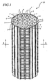
- FIG. 1 is a perspective view of an embodiment of a container with the tube assembly inside the container.
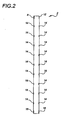
- FIG. 2 is a side view of an embodiment of tube 2 shown in FIG. 1 .
- FIG. 3 is a side view of an embodiment of tube 4 shown in FIG. 1 .
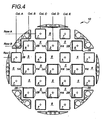
- FIG. 4 is an exploded cross section view along line AA of the container shown in FIG. 1 .
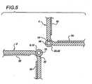
- FIG. 5 is a partial top view of an embodiment of adjacent tubes in the container shown in FIG. 1 .
- FIG. 6 is a partial side view at the top corners of an embodiment of adjacent tubes in the container shown in FIG. 1 .
- FIG. 7 is a partial side view at the bottom corners of an embodiment of adjacent tubes in the container shown in FIG. 1 .
- FIG. 8 is a partial cross section exploded view of adjacent tubes shown in FIG. 1 at the corners of the adjacent tubes.
- FIG. 9 is a partial cross section exploded view of adjacent tubes shown in FIG. 1 at the corners of the adjacent tubes when the tubes are linked together.
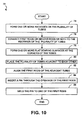
- FIG. 10 is a flow diagram that illustrates an embodiment of the process of making the container.
- the apparatus and methods can be used in both the wet and dry storage or transportation systems.
- the spent nuclear fuel is stored in a container that includes a plurality of tubes being adjacent to each other.
- Exemplary containers are discussed with reference to the figures. Although the exemplary containers are described in detail, they are provided for purposes of illustration only and various modifications are feasible. After the exemplary containers have been described, examples of operation are provided to explain the manner in which the containers are made.
- FIG. 1 is a perspective view of an embodiment of a container 10 with a tube assembly inside the container 10 that stores spent nuclear fuel.
- the container 10 includes a plurality of elongated tubes 2, 4, 6, 7 that links together to form a tube assembly.
- the elongated tubes 2, 4, 6, 7 include four sidewalls and four corners that can be arranged to form a square-like or rectangular-like cross section.
- the tubes can be arranged in other geometric shapes, e.g., circle, triangle, heptagon, hexagon and octagon.
- the tubes are mounted with first rods (not shown) or second rods (not shown) or both.
- the first rods are cylindrical and have openings that are located about the center diameter and along the length of the first rods.
- the second rods are cylindrical and have no openings.
- the first rods enable the tubes 2, 4, 6, 7 to be linked together.
- the first rods and the second rods facilitate horizontal design load transfer through the tube assembly and provide structural stability during the tube assembling and handling activities.
- the first rods and second rods can be in other geometric shapes, e.g., triangle, hexagon, and octagon. The first rods and second rods are further discussed with reference to FIGS. 2-7 .
- the tubes are referenced differently because the tubes 2 are mounted with the first rods and second rods at the four corners of the tubes 2.
- the tubes 4 are mounted with the first rods at the corners of the tubes 4 but are not mounted with the second rods.
- the tubes 6 are mounted with the first rods and second rods at the three corners that are adjacent to the tubes 4, 7.
- the fourth corners of the tubes 6 that are adjacent to the wall of the container 10 are not mounted with the first rods and second rods.
- the tubes 7 are mounted with the first rods and second rods at the two corners that are adjacent to tubes 2, 6.
- the other two corners of the tubes 7 are not mounted with the first rods and second rods.
- the first and second rods are preferred to be mounted in recesses at the corners of one tube and engage the recesses of the adjacent tube. The recesses and rods are further discussed with reference to FIGS. 5-7 .
- the tubes 2, 4, 6, 7 are linked at the corners of the tubes in alternating patterns to form a developed cell 5.
- the tubes 2, 4, 6, 7 can be linked in series along a row or column wherein the sidewalls of the tubes 2, 4, 6, 7 are adjacent to each other.
- the tubes are in another geometric shape, e.g., a hexagon, the tubes can be linked to form a honeycomb-shaped tube assembly wherein the sidewalls of the tubes are adjacent to each other.
- FIG. 2 is a side view of the tube 2 shown in FIG. 1 .
- the tube 2 includes first rods 8, 12, 16, 18. It should be noted that the tube 2 has four more first rods on the other side of the tube 2 that are not shown. Thus, the tube 2 includes four first rods adjacent to the top corners of the tube 2 and four first rods adjacent to the bottom corners of the tube 2.
- the tube 2 further includes at least one second rod 14 between the top and bottom corners of the tube 2.
- sixteen second rods 14 are mounted along the two corners of the tube 2 shown in FIG. 2 .
- the two corners of the tube 2 not shown in FIG. 2 can be mounted with second rods 14, sixteen in this example.
- the first and second rods are preferred to be mounted in the recesses at the corners of the tube 2 and engage the recesses at the corners of the adjacent tubes 4, 7.
- FIG. 3 is a side view of the tube 4 shown in FIG. 1 .
- the tube 4 includes first rods 20, 22, 24, 26. It should be noted that the tube 4 has four more first rods on the other side of the tube 4 that are not shown.
- the tube 4 includes four first rods adjacent to the top corners of the tube 4 and four first rods adjacent to the bottom corners of the tube 4.
- the tube 4 does not include any second rods between the top and bottom corners of the tube 4.
- the first rods are preferably mounted in the recesses adjacent to the top and bottom corners of the tube 4. The recesses along the corners of the tube 4 engage the first and second rods mounted on the adjacent tubes 2, 6.
- the tubes 6, 7 are not shown in the FIGS. 2 and 3 .
- the tube 6 includes first rods at the three corners adjacent to the tubes 4, 7.
- the tube 6 includes three first rods adjacent to the top corners of the tube 6 and three first rods adjacent to the bottom corners of the tube 6.
- the tube 6 further includes second rods 28 (shown in FIG. 4 ) along the three corners of the tube 6.
- the fourth corner of the tube 6 that is adjacent to the wall of the container 10 is not mounted with any first and second rods.
- the first and second rods are preferred to be mounted in the recesses at corners of the tube 6 and engage the recesses at the corners of the adjacent tubes 4, 7.
- the tube 7 includes first rods at the two corners adjacent to the tubes 2, 6.
- the tube 7 includes two first rods adjacent to the top corners of the tube 7 and two first rods adjacent to the bottom corners of the tube 7. No first rods are mounted on the two corners of the tube 7 that are not adjacent to the tubes 2, 6. Further, no second rods are mounted on the tube 7.
- the first rods are mounted in the recesses adjacent to the top and bottom corners of the tube 7. The recesses along the corners of the tube 7 engage the first and second rods mounted on the adjacent tubes 2, 6.
- first rods can be mounted not only at the corners adjacent to the top and bottom of the tubes 2, 4, 6, 7 but anywhere along the corners of the tubes.
- the first rods can further be mounted on the sidewalls of the tubes.
- the second rods can be mounted on any tubes 2, 4, 6, 7, and anywhere along the corners of the tubes and/or to the sidewalls of the tubes.
- FIG. 4 is an exploded cross section view along line AA of the container 10 shown in FIG. 1 having a plurality of tubes 2, 4, 6, 7.
- the tubes are not adjacent to each other to illustrate the tubes mounted with and without second rods.
- the tubes 2 include one or more second rod 14 at the corners of the tube 2.
- the tubes 4, 7 do not include any second rods at the corners of the tubes 4.
- the tubes 6 include one or more second rod 28 at three corners of the tubes 6.
- the fourth corners of tubes 6 adjacent to the wall of the container 10 do not include any second rods.
- one set of tubes 4, 7 are not mounted with second rods and the other set of tubes 2, 6 are mounted with second rods.
- the second rods mounted on the tubes 2, 6 engage the corners of the tubes 4, 7.
- the second rods are mounted in the recesses of the tubes 2, 6 and engage the recesses of the tubes 4, 7 when the tubes are linked together.
- the second rods can be mounted on any of the tubes 2, 4, 6, 7 anywhere along the corners of the tubes.
- the second rod is mounted on a first tube at a first location along the corner of the first tube.
- Another second rod is mounted on a second tube at a second location along the corner of the second tube.
- the tubes 2, 4, 6, 7 are arranged in alternating patterns to be linked at the corners of the tubes 2, 4, 6, 7 creating a developed cell 5.
- the tube 4 in column C, row C is adjacent at two corners to a corner of the tube 6 in column B, row B and to a corner of the tube 2 in column D, row B.
- the tube 7 in column C, row A is adjacent at two corners to another corner of the tube 6 and to another corner of the tube 2.
- This arrangement of the tubes can be linked together at the corners of the tubes 2, 4, 6, 7 to create the developed cell 5 in column C, row B.
- the linking of the tubes is further discussed with reference to Figs. 5-7 .
- the tubes 2, 4, 6, 7 can be arranged such that the sidewalls of the tubes 2, 4, 6, 7 are adjacent to each other.
- the tubes can be arranged in series along a row or a column in the container 10. Referring to FIG. 4 , the tube 7 in column C, row A can be adjacent to another tube (not shown) in column D, row A, which in turn is adjacent to the tube 7 in column E, row A.
- the tubes can be in a hexagonal shape in which the tubes can be linked to form a honeycomb-shaped tube assembly wherein the sidewalls of the tubes are adjacent to each other.
- the first rods linking the tubes 2, 4, 6, 7 can be mounted on the corners or the sidewalls of the tubes.
- FIG. 5 is a partial top view of the tubes 2, 4.
- the tubes 2, 4 include one or more poison materials 30 that are attached to the inner sidewalls of the tubes 2, 4.
- a recess 32 is formed at the corner adjacent to the top of the tube 2 and a recess 34 is formed at the corner adjacent to the top of the tube 4.
- the recesses 32, 34 are mounted with first rods 8, 12, 20, 22.
- the first rod 8, 12 is mounted in the recess 32 of the tube 2 slightly above the first rod 20, 22 mounted in the recess 34 of the tube 4 such that the openings 36, 38 of the first rods 8, 12, 20, 22 are axially aligned.
- a pin (not shown) is inserted through the openings 36, 38 of the first rods 8, 12, 20, 22 of the adjacent tubes 2, 4 to link the tubes together.
- the first rod 8, 12 of the tube 2 engages the recess 34 of the tube 4 and the first rod 20, 22 of the tube 4 engages the recess 32 of the tube 2.
- the first-rod-and-pin arrangement is further discussed with reference to Figs. 6 and 7 .
- first rods 16, 18, 24, 26 are mounted in the recesses formed adjacent to the bottom corners of the tubes 2, 4.
- the first rod 16, 18 is mounted in the recess 46 of the tube 2 slightly above the first rod 24, 26 mounted in the recess 48 of the tube 4 such that the openings 52, 54 of the first rods 16, 18, 24, 26 are axially aligned.
- a pin is inserted through the openings 52, 54 of the first rods 16, 18, 24, 26 of the adjacent tubes 2, 4 to link the tubes together.
- the first rod 16, 18 of the tube 2 engages the recess 48 of the tube 4 and the first rod 24, 26 of the tube 4 engages the recess 46 of the tube 2.
- tubes 2 are further linked to the adjacent tubes 7 and tubes 4 are further linked to adjacent tubes 6 in the same manner as described above.
- the tubes 6, 7 include the features that were mentioned above with reference to FIG. 5 .
- the tube 6 includes recesses at the three corners adjacent to the tubes 4, 7.
- three first rods are mounted in the recesses at the three corners adjacent to the top of the tube 6 and three first rods are mounted in the recesses at the three corners adjacent to the bottom of the tube 6.
- the fourth corner of the tube 6 that is adjacent to the wall of the container 10 does not include any recesses and first rods.
- the first rods of the tubes 6, 4, 7 include openings that can be axially aligned so that a pin extends through the openings of the first rods linking the tube 6 to the adjacent tubes 4, 7 together.
- the tube 7 includes recesses at two corners adjacent to the tubes 2, 6, preferably two first rods are mounted in the recesses at the two corners adjacent to the top of the tube 7 and two first rods are mounted in the recesses at the two corners adjacent to the bottom of the tube 7.
- the other two corners not adjacent to the tubes 2, 6 do not include any recesses and first rods.
- the first rods of the tubes 2, 6, 7 include openings that can be axially aligned so that a pin extends through the openings of the first rods linking the tubes 7 to the adjacent tubes 2, 6 together.
- the recesses can be formed anywhere along the corners of the tubes 2, 4, 6, 7 and can be mounted with first rods and/or second rods. Preferably, the recesses adjacent to the top and bottom corners of the tubes 2, 4, 6, 7 are mounted with the first rods as mentioned above.
- the recesses between the top and bottom corners of the tubes 2, 6 receives the second rods 14, 28. When the tubes 2, 4, 6, 7 are linked together, the second rods 14, 28 mounted on the tubes 2, 6 engage the recesses of the tubes 4, 7.
- the sidewalls of the tubes can be aligned in a substantially straight line to the sidewalls of the tubes. This enables the tube assembly to distribute the horizontal bearing load transfer through the sidewalls of the tubes to the container walls.
- An advantage, among others, is that the distribution of load to the sidewalls decreases the use of welding and tube wall materials needed to bear the large compressive loads set forth in the regulations and codes for spent nuclear fuel containers. The distribution of the load to the sidewalls eliminates the stress and high moments directly on the welds that could be used to join the adjacent tubes because the sidewalls, rods, and recesses transmit the compressive loads.
- the recesses are semi-circular to receive the cylindrical shaped first and second rods.
- the recesses can be formed to receive the different geometric shapes of the first rods and the second rods.
- the recesses can be formed to receive three of the six sidewalls of the hexagonal rods.
- the recesses can be formed on the sidewalls of the tubes 2, 4, 6, 7 and are mounted with first rods and/or second rods.
- FIG. 6 is a partial side view that shows an attachment mechanism of the tube assembly at the top corners of the tubes 2, 4.
- the attachment mechanism includes first rods 8, 12, 20, 22 and a pin 40.
- the first rods 8, 12, 20, 22 can be mounted in the recesses 32, 34 that are formed at the corners adjacent to the top of the tubes 2, 4.
- the first rods 8, 12, 20, 22 are positioned along the recesses 32, 34 of the tubes 2, 4 so that the first rods can be aligned to extend the pin 40 through the openings 36, 38 of the aligned first rods to link the adjacent tubes 2, 4.
- the pin 40 can include a head portion 42 and a body portion 44.
- the body portion 44 of the pin 40 extends through openings 36, 28 of the first rods 8, 12, 20, 22.
- the head portion 42 is placed adjacent to the first rod 8, 12 and the recess 32 of the tube 2, and can be welded to or otherwise captured by the first rod 8, 12 and the recess 32 of the tube 2.
- the pin 40 may be captured by one tube, which in this example, is tube 2.
- FIG. 7 is a partial side view that shows an attachment mechanism at the bottom corners of the tubes 2, 4.
- the attachment mechanism includes first rods 16, 18, 24, 26 and a pin 50.
- the first rods can be mounted in the recesses 46, 48 that are formed at the corners adjacent to the bottom of the tubes 2, 6.
- the first rods 16, 18, 24, 26 are positioned along the recesses 46, 48 of tubes 2, 4 so that the first rods can be aligned to extend the pin 50 through the openings 52, 54 of the aligned first rods to link the adjacent tubes 2, 4.
- the pin 50 can include a head portion 56 and a body portion 58.
- the body portion 58 of the pin 50 extends through openings 52, 54 of the first rods 16, 18, 24, 26.
- the head portion 56 is placed adjacent to the first rod 24, 26 and the recess 48 of the tube 4, and can be welded to or otherwise captured by the first rod 24, 26 and the recess 48 of the tube 4.
- the pin 50 may be captured by one tube, which in this example, is tube 4.
- the attachment mechanism discussed with reference to FIGS. 6 and 7 can be placed anywhere along the corners of the tubes 2, 4 and can link the tubes to each other to form a tube assembly.
- the attachment mechanism facilitates horizontal bearing load transfer through the tube assembly to the container walls and provides the flexibility for linking the tubes 2, 4, 6, 7 in a continuous array across the tube assembly. Further, the tube assembly can be handled external to the container 10 as a unit rather than as individual pieces.
- FIG. 8 is a partial cross section view of the tubes 2, 4 that includes flat bearing surfaces 60, 62 formed along the corners of the tubes 2, 4 where the recesses 32, 34, 46, 48 are not formed. The tubes are not adjacent to each other to better illustrate the flat bearing surfaces 60, 62.
- FIG. 9 is a partial cross section view that shows the flat bearing surface 60 of the tubes 2 engaging the flat bearing surface 62 of the tubes 4 when the tubes 2, 4 are linked.
- the flat bearing surfaces 60, 62 can facilitate aligning the sidewalls of the tube 2 in a substantially straight line to the sidewalls of the tube 4.
- sidewall 64 of the tube 4 is aligned in a substantially straight line with sidewall 66 of the tube 2.
- Sidewall 70 of the tube 4 is aligned in a substantially straight line with sidewall 68 of the tube 2. This facilitates horizontal bearing load transfer through the tube assembly to the container walls.
- the tubes 2, 4, 6, 7 include flat bearing surfaces at the corners of the respective tubes.
- FIG. 10 is a flow diagram that illustrates an embodiment of the process 72 of making the container for storing spent nuclear fuel. Beginning with block 74, one or more recesses are formed on the plurality of tubes, preferably at the corners of the tubes. In an alternative embodiment, the recesses can be formed on the sidewalls of the tubes.
- the recesses can be mounted with the first rods or second rods or both.
- the second rods are mounted on one set of tubes and no second rods are mounted on another set of tubes.
- one or more flat bearing surfaces are formed along the corners of the tubes, preferably where the recesses are not formed. The flat bearing surfaces of the tubes are adjacent and can engage each other when the tubes are linked.
- a plurality of tubes is placed adjacent to each other, preferably along the corners of the tubes such that the sidewalls of the tubes are aligned in a substantially straight line. Further, it is also preferable to place four tubes in alternating patterns to create a developed cell.
- the tubes can be arranged such that the sidewalls of the tubes are adjacent to each other. For example, if the tubes are shaped in a rectangular cross section, the rectangular tubes can be arranged in series. If the tubes are shaped in a hexagonal cross section, the hexagonal tubes can be arranged in a honeycomb formation.
- the first rods of the adjacent tubes are aligned.
- one or more pins are inserted through the openings of the aligned first rods.
- the pin can be welded to or otherwise captured by the first rods of one of the adjacent tubes.
- a container for storing spent nuclear fuel comprises a plurality of elongated tubes that receives spent nuclear fuel rods. Each tube has four sidewalls and four corners defining a rectangular cross section. The plurality of tubes is arranged in an alternating pattern. An attachment means attaches together the plurality of tubes at the corners so that two adjacent sidewalls of adjacent tubes are substantially aligned.
- a container for storing spent nuclear fuel comprises a plurality of tubes, a plurality of first rods, and one or more pins.
- the plurality of tubes receives spent nuclear fuel assemblies.
- the plurality of first rods has openings and is mounted on the plurality of tubes. The first rods are aligned so that one or more pins extend through the openings of the first rods linking the tubes together.
- a container for storing or transporting spent nuclear fuel comprises a plurality of tubes and a plurality of first rods.
- the plurality of tubes receives nuclear spent fuel assemblies and the tubes are adjacent to each other.
- the plurality of tubes has a plurality of recesses that receives the plurality of first rods. Some of the plurality of first rods mounted in the recesses of the adjacent tubes are attached to others of the plurality of first rods linking the tubes together.
- a container for storing spent nuclear fuel comprises a plurality of elongated tubes and a plurality of first rods.
- the plurality of elongated tubes receives spent nuclear fuel rods.
- Each tube has four sidewalls and four corners defining a rectangular cross section.
- the plurality of tubes is arranged in an alternating pattern.
- the tubes have a plurality of recesses and a plurality of flat bearing surfaces along at least one corner of the tubes.
- the plurality of first rods is mounted in the plurality of recesses at the corners of the plurality of the tubes. Some of the plurality of first rods mounted on the adjacent tubes are attached to others of the plurality of first rods linking the tubes together.
- the plurality of the tubes is linked at the corners such that the plurality of flat bearing surfaces of the adjacent tubes engages each other and the two adjacent sidewalls of the adjacent tubes are aligned.
- an attachment mechanism for a tube assembly that stores or transport spent nuclear fuel includes one or more pins and a plurality of first rods being mounted on a plurality of tubes.
- the first rods have openings and are aligned so that the one or more pins extend through the openings of the plurality of first rods.
- Such a method can be broadly summarized by the following steps: forming one or more recesses on a plurality of tubes, mounting a plurality of first rods in the recesses of the plurality of tubes, placing the plurality of tubes adjacent to each other, aligning the plurality of first rods, and inserting one or more pins through the aligned openings of the plurality of first rods to link the plurality of tubes.
Landscapes
- Physics & Mathematics (AREA)
- Engineering & Computer Science (AREA)
- General Engineering & Computer Science (AREA)
- High Energy & Nuclear Physics (AREA)
- Plasma & Fusion (AREA)
- Packaging Of Annular Or Rod-Shaped Articles, Wearing Apparel, Cassettes, Or The Like (AREA)
- Stackable Containers (AREA)
- Packages (AREA)
- Pallets (AREA)
Abstract
Description
- This application claims priority to copending U.S. provisional application entitled, "Container and Method for Storing Spent Nuclear Fuel", having ser. No.
60/535,884, filed January 12, 2004 60/510,385, filed October 10, 2003 - The present invention relates to containers for storing or transporting spent nuclear fuel.
- Typically, spent nuclear fuel discharged from fission reactors is stored in deep pools filled with water to dissipate heat and to attenuate the gamma and neutron radiation generated by the fuel. This is called a wet storage system. An alternative method to storing the spent nuclear fuel is a dry storage system that uses a horizontal or vertical configuration having either a heavy wall protected vessel referred to as a cask or over-pack, or a thin walled vessel called a canister. Dry storage systems can also be used to transport spent fuel between storage locations. For dry storage system, the canister can be separately placed into the cask or over-pack.
- The structure that provides support for the spent nuclear fuel for dry storage and transportation systems is referred to as a fuel basket. The fuel baskets are designed to meet the compressive loads criteria contained within regulations, codes, and standards, particularly conditions for storing and transporting nuclear spent fuel. Dry storage and transportation basket designs include a tube and disk flux trap configuration, an egg crate interlocking plate configuration, a developed cell configuration and a stacked tube configuration.
-
WO 00/72326 A1 - The container disclosed in
US 4,652,422 is built with tubes having a circular cross-section. Adjacent tubes carry rigid lugs extending in radial outward direction from the tubes. The lugs are arranged in the respective cross-sectional plane in stellar fashion at an angular spacing of 90° from one another. The rigid lugs have slots having an axial or radial direction. Adjacent tubes are connected with each other by a screw extending through the slots. The length of the lugs defines the minimal distance of adjacent tubes. -
US 4,630,738 discloses a rack for storing nuclear fuel elements built with square tubes wherein the square tubes are built with two angled plates welded with each other. Two of the four edges of the tube are in the form of a bend while the tow other edges are in the form of a weld. In addition, neutron-absorbent plates are fitted on the four sides of each of the square tubes. Furthermore, a square surrounding additional tube encloses the unit defined by the aforementioned square tube and the neutron-absorbent plates. Also the surrounding tube is welded from two angled plates. The resulting "double-walled" tubes are connected with each other by joints laterally securing the adjacent tubes. The joints are built by L-shaped bars extending in outward directions from the corners of the surrounding tubes wherein the L-shaped bars are welded with the surrounding tube. The bars have bores for screwing adjacent double-walled tubes with each other. Also for this embodiment the distance of adjacent tubes in the assembled state correlates with the extension of the connecting elements, here the bars. The bars have to be screwed in horizontal direction wherein the screws are accessed through the intermediate space built between adjacent double-walled tubes. -
US 4,034,227 discloses a nuclear fuel storage rack for high density nuclear fuel storage inside a fuel pool. The rack is located in a pool having a concrete enclosure or well constituted offside walls and a bottom floor housing a pool of water. In the rack square enclosures define an internal channels as well as external channels with neighbouring enclosures or with an additional side enclosure panel for the peripheral enclosures. The enclosures are built with U-shaped members joint with each other at their front surfaces to form a rectangle. To complete the rectangular enclosure for the slots along the periphery of the assembly, also the use of an elongated side enclosure panel is suggested. The enclosure walls contain a series of oppositely-directed projecting portions wherein the outwardly-directed projecting portion is offset laterally from an inwardly-directed portion. These portions form continuous longitudinal circular grooves for receiving poison pins. In addition, each of the corners is provided with a continuous longitudinal groove for receiving slot connector bars or side panel ends for interconnecting corners of adjacent enclosures to each other to form the rigid rack assembly. The complex contours of the members and panels are formed by extrusion, rolling and/or forming. For the connection of adjacent square enclosures at corner grooves the document suggests using slot connector bars or X-shaped bars. For the use of the slot connector bar protrusions extend from the corners of the enclosures. Two abutting protrusions build a longitudinal slot having a barbell-shaped cross-section. The slot connector bar also having a barbell shaped outer contour is introduced in longitudinal direction into the opening positively connecting the adjacent tubes with each other. The tubes build a cross-like pattern wherein adjacent channels are separated by one single side wall and every second channel is not defined by one single tube but by side walls of four adjacent tubes. -
FR 2 482 354 - An apparatus for the storage and transport of spent nuclear fuel according to the invention is defined in independent claim 1. Dependent claims 2 to 4 define further embodiments of the invention. A method for the storage and transport of spent nuclear fuel is defined in
independent claim 5. Further embodiments of such method are defined independent claims 6 to 9. - Other apparatus, methods, features, and advantages of the present disclosure will be apparent to one skilled in the art upon examination of the following drawings and detailed description. It is intended that all such additional apparatus, methods, features, and advantages be included within this description and be protected by the accompanying claims.
- The disclosed apparatus and methods can be better understood with reference to the following drawings. The components in the drawings are not necessarily to scale.
-
FIG. 1 is a perspective view of an embodiment of a container with the tube assembly inside the container. -
FIG. 2 is a side view of an embodiment oftube 2 shown inFIG. 1 . -
FIG. 3 is a side view of an embodiment oftube 4 shown inFIG. 1 . -
FIG. 4 is an exploded cross section view along line AA of the container shown inFIG. 1 . -
FIG. 5 is a partial top view of an embodiment of adjacent tubes in the container shown inFIG. 1 . -
FIG. 6 is a partial side view at the top corners of an embodiment of adjacent tubes in the container shown inFIG. 1 . -
FIG. 7 is a partial side view at the bottom corners of an embodiment of adjacent tubes in the container shown inFIG. 1 . -
FIG. 8 is a partial cross section exploded view of adjacent tubes shown inFIG. 1 at the corners of the adjacent tubes. -
FIG. 9 is a partial cross section exploded view of adjacent tubes shown inFIG. 1 at the corners of the adjacent tubes when the tubes are linked together. -
FIG. 10 is a flow diagram that illustrates an embodiment of the process of making the container. - Disclosed are apparatus and methods for a container that stores or transport spent nuclear fuel. The apparatus and methods can be used in both the wet and dry storage or transportation systems. In particular, the spent nuclear fuel is stored in a container that includes a plurality of tubes being adjacent to each other. Exemplary containers are discussed with reference to the figures. Although the exemplary containers are described in detail, they are provided for purposes of illustration only and various modifications are feasible. After the exemplary containers have been described, examples of operation are provided to explain the manner in which the containers are made.
- Referring now in more detail to the figures in which like reference numerals identify corresponding parts,
FIG. 1 is a perspective view of an embodiment of acontainer 10 with a tube assembly inside thecontainer 10 that stores spent nuclear fuel. As indicated in this figure, thecontainer 10 includes a plurality ofelongated tubes elongated tubes - The tubes are mounted with first rods (not shown) or second rods (not shown) or both. Preferably, the first rods are cylindrical and have openings that are located about the center diameter and along the length of the first rods. The second rods are cylindrical and have no openings. The first rods enable the
tubes FIGS. 2-7 . - Referring to
FIG. 1 , the tubes are referenced differently because thetubes 2 are mounted with the first rods and second rods at the four corners of thetubes 2. Thetubes 4 are mounted with the first rods at the corners of thetubes 4 but are not mounted with the second rods. Thetubes 6 are mounted with the first rods and second rods at the three corners that are adjacent to thetubes tubes 6 that are adjacent to the wall of thecontainer 10 are not mounted with the first rods and second rods. Thetubes 7 are mounted with the first rods and second rods at the two corners that are adjacent totubes tubes 7 are not mounted with the first rods and second rods. The first and second rods are preferred to be mounted in recesses at the corners of one tube and engage the recesses of the adjacent tube. The recesses and rods are further discussed with reference toFIGS. 5-7 . - Referring to
FIG. 1 , thetubes developed cell 5. Alternatively, thetubes tubes -
FIG. 2 is a side view of thetube 2 shown inFIG. 1 . Thetube 2 includesfirst rods tube 2 has four more first rods on the other side of thetube 2 that are not shown. Thus, thetube 2 includes four first rods adjacent to the top corners of thetube 2 and four first rods adjacent to the bottom corners of thetube 2. Thetube 2 further includes at least onesecond rod 14 between the top and bottom corners of thetube 2. For example, sixteensecond rods 14 are mounted along the two corners of thetube 2 shown inFIG. 2 . The two corners of thetube 2 not shown inFIG. 2 can be mounted withsecond rods 14, sixteen in this example. The first and second rods are preferred to be mounted in the recesses at the corners of thetube 2 and engage the recesses at the corners of theadjacent tubes -
FIG. 3 is a side view of thetube 4 shown inFIG. 1 . Thetube 4 includesfirst rods tube 4 has four more first rods on the other side of thetube 4 that are not shown. Thus, thetube 4 includes four first rods adjacent to the top corners of thetube 4 and four first rods adjacent to the bottom corners of thetube 4. Thetube 4 does not include any second rods between the top and bottom corners of thetube 4. The first rods are preferably mounted in the recesses adjacent to the top and bottom corners of thetube 4. The recesses along the corners of thetube 4 engage the first and second rods mounted on theadjacent tubes - The
tubes FIGS. 2 and3 . However, it should be noted that thetube 6 includes first rods at the three corners adjacent to thetubes tube 6 includes three first rods adjacent to the top corners of thetube 6 and three first rods adjacent to the bottom corners of thetube 6. Thetube 6 further includes second rods 28 (shown inFIG. 4 ) along the three corners of thetube 6. The fourth corner of thetube 6 that is adjacent to the wall of thecontainer 10 is not mounted with any first and second rods. The first and second rods are preferred to be mounted in the recesses at corners of thetube 6 and engage the recesses at the corners of theadjacent tubes - The
tube 7 includes first rods at the two corners adjacent to thetubes tube 7 includes two first rods adjacent to the top corners of thetube 7 and two first rods adjacent to the bottom corners of thetube 7. No first rods are mounted on the two corners of thetube 7 that are not adjacent to thetubes tube 7. The first rods are mounted in the recesses adjacent to the top and bottom corners of thetube 7. The recesses along the corners of thetube 7 engage the first and second rods mounted on theadjacent tubes - In an alternative embodiment, the first rods can be mounted not only at the corners adjacent to the top and bottom of the
tubes tubes -
FIG. 4 is an exploded cross section view along line AA of thecontainer 10 shown inFIG. 1 having a plurality oftubes tubes 2 include one or moresecond rod 14 at the corners of thetube 2. Thetubes tubes 4. Thetubes 6 include one or moresecond rod 28 at three corners of thetubes 6. The fourth corners oftubes 6 adjacent to the wall of thecontainer 10 do not include any second rods. In short, one set oftubes tubes tubes tubes tubes tubes - In an alternative embodiment, the second rods can be mounted on any of the
tubes - Preferably, the
tubes tubes developed cell 5. For example, thetube 4 in column C, row C is adjacent at two corners to a corner of thetube 6 in column B, row B and to a corner of thetube 2 in column D, row B. Thetube 7 in column C, row A is adjacent at two corners to another corner of thetube 6 and to another corner of thetube 2. This arrangement of the tubes can be linked together at the corners of thetubes developed cell 5 in column C, row B. The linking of the tubes is further discussed with reference toFigs. 5-7 . - In an alternative embodiment, the
tubes tubes container 10. Referring toFIG. 4 , thetube 7 in column C, row A can be adjacent to another tube (not shown) in column D, row A, which in turn is adjacent to thetube 7 in column E, row A. In another example, the tubes can be in a hexagonal shape in which the tubes can be linked to form a honeycomb-shaped tube assembly wherein the sidewalls of the tubes are adjacent to each other. In both examples, the first rods linking thetubes -
FIG. 5 is a partial top view of thetubes tubes more poison materials 30 that are attached to the inner sidewalls of thetubes recess 32 is formed at the corner adjacent to the top of thetube 2 and arecess 34 is formed at the corner adjacent to the top of thetube 4. Therecesses first rods first rod 8, 12 is mounted in therecess 32 of thetube 2 slightly above thefirst rod recess 34 of thetube 4 such that theopenings first rods openings first rods adjacent tubes first rod 8, 12 of thetube 2 engages therecess 34 of thetube 4 and thefirst rod tube 4 engages therecess 32 of thetube 2. The first-rod-and-pin arrangement is further discussed with reference toFigs. 6 and7 . - It should be noted that the bottom corners of the
tubes FIG. 5 . For example,first rods tubes first rod recess 46 of thetube 2 slightly above thefirst rod recess 48 of thetube 4 such that theopenings first rods openings first rods adjacent tubes first rod tube 2 engages therecess 48 of thetube 4 and thefirst rod tube 4 engages therecess 46 of thetube 2. It should be noted thattubes 2 are further linked to theadjacent tubes 7 andtubes 4 are further linked toadjacent tubes 6 in the same manner as described above. - In addition, the
tubes 6, 7 (not shown inFIG. 5 ) include the features that were mentioned above with reference toFIG. 5 . Thetube 6 includes recesses at the three corners adjacent to thetubes tube 6 and three first rods are mounted in the recesses at the three corners adjacent to the bottom of thetube 6. The fourth corner of thetube 6 that is adjacent to the wall of thecontainer 10 does not include any recesses and first rods. The first rods of thetubes tube 6 to theadjacent tubes - The
tube 7 includes recesses at two corners adjacent to thetubes tube 7 and two first rods are mounted in the recesses at the two corners adjacent to the bottom of thetube 7. The other two corners not adjacent to thetubes tubes tubes 7 to theadjacent tubes - The recesses can be formed anywhere along the corners of the
tubes tubes tubes second rods tubes second rods tubes tubes - By coupling the first rods and second rods in the recesses, the sidewalls of the tubes can be aligned in a substantially straight line to the sidewalls of the tubes. This enables the tube assembly to distribute the horizontal bearing load transfer through the sidewalls of the tubes to the container walls. An advantage, among others, is that the distribution of load to the sidewalls decreases the use of welding and tube wall materials needed to bear the large compressive loads set forth in the regulations and codes for spent nuclear fuel containers. The distribution of the load to the sidewalls eliminates the stress and high moments directly on the welds that could be used to join the adjacent tubes because the sidewalls, rods, and recesses transmit the compressive loads.
- Preferably, the recesses are semi-circular to receive the cylindrical shaped first and second rods. In an alternative embodiment, the recesses can be formed to receive the different geometric shapes of the first rods and the second rods. For example, if the rods are in a hexagonal shape, the recess can be formed to receive three of the six sidewalls of the hexagonal rods. In another alternative embodiment, the recesses can be formed on the sidewalls of the
tubes -
FIG. 6 is a partial side view that shows an attachment mechanism of the tube assembly at the top corners of thetubes first rods pin 40. Thefirst rods recesses tubes first rods recesses tubes pin 40 through theopenings adjacent tubes pin 40 can include ahead portion 42 and abody portion 44. Thebody portion 44 of thepin 40 extends throughopenings first rods head portion 42 is placed adjacent to thefirst rod 8, 12 and therecess 32 of thetube 2, and can be welded to or otherwise captured by thefirst rod 8, 12 and therecess 32 of thetube 2. Thus, thepin 40 may be captured by one tube, which in this example, istube 2. -
FIG. 7 is a partial side view that shows an attachment mechanism at the bottom corners of thetubes first rods pin 50. The first rods can be mounted in therecesses tubes first rods recesses tubes pin 50 through theopenings adjacent tubes pin 50 can include ahead portion 56 and abody portion 58. Thebody portion 58 of thepin 50 extends throughopenings first rods head portion 56 is placed adjacent to thefirst rod recess 48 of thetube 4, and can be welded to or otherwise captured by thefirst rod recess 48 of thetube 4. Thus, thepin 50 may be captured by one tube, which in this example, istube 4. - The attachment mechanism discussed with reference to
FIGS. 6 and7 can be placed anywhere along the corners of thetubes tubes container 10 as a unit rather than as individual pieces. -
FIG. 8 is a partial cross section view of thetubes tubes recesses FIG. 9 is a partial cross section view that shows theflat bearing surface 60 of thetubes 2 engaging theflat bearing surface 62 of thetubes 4 when thetubes - When the
tubes tube 2 in a substantially straight line to the sidewalls of thetube 4. For example,sidewall 64 of thetube 4 is aligned in a substantially straight line withsidewall 66 of thetube 2.Sidewall 70 of thetube 4 is aligned in a substantially straight line withsidewall 68 of thetube 2. This facilitates horizontal bearing load transfer through the tube assembly to the container walls. It should be noted that thetubes -
FIG. 10 is a flow diagram that illustrates an embodiment of theprocess 72 of making the container for storing spent nuclear fuel. Beginning withblock 74, one or more recesses are formed on the plurality of tubes, preferably at the corners of the tubes. In an alternative embodiment, the recesses can be formed on the sidewalls of the tubes. - In
block 76, the recesses can be mounted with the first rods or second rods or both. Preferably, the second rods are mounted on one set of tubes and no second rods are mounted on another set of tubes. Inblock 78, one or more flat bearing surfaces are formed along the corners of the tubes, preferably where the recesses are not formed. The flat bearing surfaces of the tubes are adjacent and can engage each other when the tubes are linked. - In
block 80, a plurality of tubes is placed adjacent to each other, preferably along the corners of the tubes such that the sidewalls of the tubes are aligned in a substantially straight line. Further, it is also preferable to place four tubes in alternating patterns to create a developed cell. In an alternative embodiment, the tubes can be arranged such that the sidewalls of the tubes are adjacent to each other. For example, if the tubes are shaped in a rectangular cross section, the rectangular tubes can be arranged in series. If the tubes are shaped in a hexagonal cross section, the hexagonal tubes can be arranged in a honeycomb formation. - In
block 82, the first rods of the adjacent tubes are aligned. Inblock 84, one or more pins are inserted through the openings of the aligned first rods. Inblock 86, the pin can be welded to or otherwise captured by the first rods of one of the adjacent tubes. - It should be emphasized that the above-described embodiments of the present disclosure, particularly any "preferred" embodiments, are merely possible examples of implementations, set forth only for a clear understanding of the principles of the disclosure. Many variations and modifications may be made to the above-described embodiment(s) of the disclosure without departing substantially from the principles of the disclosure. All such modifications and variations are intended to be included herein within the scope of this disclosure protected by the following claims.
- Disclosed are apparatus and methods for making a container that stores spent nuclear fuel. In one example, among others, a container for storing spent nuclear fuel comprises a plurality of elongated tubes that receives spent nuclear fuel rods. Each tube has four sidewalls and four corners defining a rectangular cross section. The plurality of tubes is arranged in an alternating pattern. An attachment means attaches together the plurality of tubes at the corners so that two adjacent sidewalls of adjacent tubes are substantially aligned.
- In another example, a container for storing spent nuclear fuel comprises a plurality of tubes, a plurality of first rods, and one or more pins. The plurality of tubes receives spent nuclear fuel assemblies. The plurality of first rods has openings and is mounted on the plurality of tubes. The first rods are aligned so that one or more pins extend through the openings of the first rods linking the tubes together.
- In another example, a container for storing or transporting spent nuclear fuel comprises a plurality of tubes and a plurality of first rods. The plurality of tubes receives nuclear spent fuel assemblies and the tubes are adjacent to each other. The plurality of tubes has a plurality of recesses that receives the plurality of first rods. Some of the plurality of first rods mounted in the recesses of the adjacent tubes are attached to others of the plurality of first rods linking the tubes together.
- In another example, a container for storing spent nuclear fuel comprises a plurality of elongated tubes and a plurality of first rods. The plurality of elongated tubes receives spent nuclear fuel rods. Each tube has four sidewalls and four corners defining a rectangular cross section. The plurality of tubes is arranged in an alternating pattern. The tubes have a plurality of recesses and a plurality of flat bearing surfaces along at least one corner of the tubes. The plurality of first rods is mounted in the plurality of recesses at the corners of the plurality of the tubes. Some of the plurality of first rods mounted on the adjacent tubes are attached to others of the plurality of first rods linking the tubes together. The plurality of the tubes is linked at the corners such that the plurality of flat bearing surfaces of the adjacent tubes engages each other and the two adjacent sidewalls of the adjacent tubes are aligned.
- In one example, an attachment mechanism for a tube assembly that stores or transport spent nuclear fuel is provided. The attachment mechanism includes one or more pins and a plurality of first rods being mounted on a plurality of tubes. The first rods have openings and are aligned so that the one or more pins extend through the openings of the plurality of first rods.
- Further, it is possible to provide a method of making a container for storing or transporting spent nuclear fuel. Such a method can be broadly summarized by the following steps: forming one or more recesses on a plurality of tubes, mounting a plurality of first rods in the recesses of the plurality of tubes, placing the plurality of tubes adjacent to each other, aligning the plurality of first rods, and inserting one or more pins through the aligned openings of the plurality of first rods to link the plurality of tubes.
Claims (9)
- A container 10 for storing or transporting spent nuclear fuel, the container comprising:a plurality of tubes (2, 4, 6, 7) that receives spent nuclear rods;a plurality of first rods (8, 12, 16, 18) being mounted on the plurality of tubes (2, 4, 6, 7), said first rods (8, 12, 16, 18) having openings (36, 38, 52, 54); andone or more pins (40, 50);wherein the plurality of first rods (8, 12, 16, 18) is aligned so that the one or more pins (40, 50) extend through the openings (36, 38, 52, 54) of the plurality of first rods (8, 12, 16, 18) linking the tubes (2, 4, 6, 7) together and each of the plurality of tubes (2, 4, 6, 7) includes a plurality of recesses (32, 34, 46, 48) on the plurality of tubes, the first rods (8, 12, 16, 18) being mounted in the recesses (32, 34, 46, 48) of one of the adjacent tube (2, 4, 6, 7) and engaging the recesses (32, 34, 46, 48) of the other adjacent tube (2, 4, 6, 7) when the tubes (2, 4, 6, 7) are linked together.
- The container as defined in claim 1, wherein the one or more pins (40, 50) comprise a head portion (42, 56) and a body portion (44, 58), the body portion (44, 58) extending through the openings (36, 38, 52, 54) of the aligned first rods (8, 12, 16, 18) of adjacent tubes (2, 4, 6, 7) and the head portion (42, 56) being adjacent to one of the plurality of first rods (8, 12, 16, 18) coupled together.
- The container as defined in claim 1, wherein the plurality of tubes (2, 4, 6, 7) has four sidewalls and four corners defining a rectangular cross section, the plurality of recesses (32, 34, 46, 48) being formed at the corners of the plurality of tubes (2, 4, 6, 7) and the first rods (8, 12, 16, 18) being mounted in the recesses (32, 34, 46, 48) of one of the adjacent tube (2, 4, 6, 7) and engaging the recesses of the other adjacent tube (2, 4, 6, 7) when the tubes (2, 4, 6, 7) are linked together,
wherein the plurality of tubes (2, 4, 6, 7) being arranged in an alternating pattern, the plurality of tubes (2, 4, 6, 7) being linked together at the corners so that two adjacent sidewalls (64, 66, 68, 70) of adjacent tubes are substantially aligned. - The container as defined in claim 3, wherein the plurality of tubes (2, 4, 6, 7) includes a plurality of flat bearing surfaces (60, 62) at the corner of the tubes (2, 4, 6, 7), the plurality of flat bearing surfaces (60, 62) of the adjacent tubes (2, 4, 6, 7) engaging each other when the tubes (2, 4, 6, 7) are linked together.
- A method of making a container for storing or transporting spent nuclear fuel, the method comprising the steps of:forming one or more recesses (32, 34, 46, 48) on a plurality of tubes (2, 4, 6, 7);mounting a plurality of first rods (8, 12, 16, 18) in the recesses (32, 34, 46, 48) of the plurality of tubes (2, 4, 6, 7);placing the plurality of tubes (2, 4, 6, 7) adjacent to each other aligning the plurality of first rods (8, 12, 16, 18); andinserting one or more pins (40, 50) through the aligned openings (36, 38, 52, 54) of the plurality of first rods (8, 12,16, 18) to link the plurality of tubes (2, 4, 6, 7)wherein each of the plurality of tubes (2, 4, 6, 7) includes a plurality of recesses (32, 34, 46, 48) on the plurality of tubes, the first rods (8, 12, 16, 18) being mounted in the recesses (32, 34, 46, 48) of one of the adjacent tube (2, 4, 6, 7) and engaging the recesses (32, 34, 46, 48) of the other adjacent tube (2, 4, 6, 7) when the tubes (2, 4, 6, 7) are linked together.
- The method as defined in claim 5, comprising the step of forming one or more recesses (32, 34, 46, 48) along one or more corners of the plurality of tubes (2, 4, 6, 7) or on the sidewalls of the plurality of tube.
- The method as defined in claim 5, wherein placing the plurality of tubes (2, 4, 6, 7) adjacent to each other comprises aligning the sidewalls (64, 66, 68, 70) of the plurality of tubes (2, 4, 6, 7) in a substantially straight line.
- The method as defined in claim 5, further comprising mounting one or more second rods (14, 28) in the recesses of the plurality of tubes (2, 4, 6, 7).
- The method as defined in claim 5, further comprising forming a plurality of flat bearing surfaces (60, 62) at the corners of the tubes and engaging the flat bearing surfaces (60, 62) of the adjacent tubes (2, 4, 6, 7) adjacent to each other when the tubes (2, 4, 6, 7) are linked together.
Applications Claiming Priority (4)
| Application Number | Priority Date | Filing Date | Title |
|---|---|---|---|
| US51038503P | 2003-10-10 | 2003-10-10 | |
| US53588404P | 2004-01-12 | 2004-01-12 | |
| US10/795,879 US8630384B2 (en) | 2003-10-10 | 2004-03-08 | Container and method for storing or transporting spent nuclear fuel |
| PCT/US2004/033034 WO2005035373A2 (en) | 2003-10-10 | 2004-10-07 | Container and method for storing or transporting spent nuclear fuel |
Publications (3)
| Publication Number | Publication Date |
|---|---|
| EP1680326A2 EP1680326A2 (en) | 2006-07-19 |
| EP1680326A4 EP1680326A4 (en) | 2007-05-30 |
| EP1680326B1 true EP1680326B1 (en) | 2011-12-21 |
Family
ID=34437671
Family Applications (1)
| Application Number | Title | Priority Date | Filing Date |
|---|---|---|---|
| EP04809885A Expired - Lifetime EP1680326B1 (en) | 2003-10-10 | 2004-10-07 | Container and method for storing or transporting spent nuclear fuel |
Country Status (7)
| Country | Link |
|---|---|
| US (1) | US8630384B2 (en) |
| EP (1) | EP1680326B1 (en) |
| JP (1) | JP4895817B2 (en) |
| AT (1) | ATE538477T1 (en) |
| ES (1) | ES2379175T3 (en) |
| RU (1) | RU2369927C2 (en) |
| WO (1) | WO2005035373A2 (en) |
Families Citing this family (23)
| Publication number | Priority date | Publication date | Assignee | Title |
|---|---|---|---|---|
| US8187720B2 (en) * | 2005-11-14 | 2012-05-29 | Lawrence Livermore National Security, Llc | Corrosion resistant neutron absorbing coatings |
| US8712001B2 (en) * | 2006-06-30 | 2014-04-29 | Holtec International, Inc. | Fuel basket spacer, apparatus and method using the same for storing high level radioactive waste |
| US12033764B2 (en) | 2006-09-06 | 2024-07-09 | Holtec International | Fuel rack for storing spent nuclear fuel |
| CN101960534B (en) | 2007-10-29 | 2014-08-20 | 霍尔泰克国际股份有限公司 | Apparatus for supporting radioactive fuel assemblies |
| US8681924B2 (en) * | 2008-04-29 | 2014-03-25 | Holtec International | Single-plate neutron absorbing apparatus and method of manufacturing the same |
| US11569001B2 (en) | 2008-04-29 | 2023-01-31 | Holtec International | Autonomous self-powered system for removing thermal energy from pools of liquid heated by radioactive materials |
| US8146310B2 (en) * | 2009-03-11 | 2012-04-03 | Keene Building Products Co., Inc. | Noise control flooring system |
| WO2011034886A1 (en) | 2009-09-15 | 2011-03-24 | Nac International, Inc. | System and method for integration of wet and dry nuclear fuel storage |
| JP2014529737A (en) * | 2011-08-19 | 2014-11-13 | ホルテック・インターナショナル・インコーポレーテッド | Container and system for handling damaged nuclear fuel and method of manufacturing the same |
| US11515054B2 (en) | 2011-08-19 | 2022-11-29 | Holtec International | Method of retrofitting a spent nuclear fuel storage system |
| WO2014022763A2 (en) | 2012-08-02 | 2014-02-06 | Nac International, Inc. | Systems and methods for dry storage and/or transport of consolidated nuclear spent fuel rods |
| JP6253881B2 (en) * | 2012-11-30 | 2017-12-27 | 三菱重工業株式会社 | Radioactive substance storage basket and radioactive substance storage container |
| BE1021571B1 (en) | 2013-03-13 | 2015-12-14 | Cockerill Maintenance & Ingeniere S.A. | INTEGRATED SYSTEM FOR THE CONSTRUCTION AND TRANSPORT OF PACKAGING ASSEMBLIES AND THEIR ASSEMBLY, FILLING AND DISASSEMBLING STATIONS |
| KR102305376B1 (en) | 2013-10-02 | 2021-09-27 | 낵 인터내셔날, 인크 | Systems and methods for transferring spent nuclear fuel from wet storage to dry storage |
| KR101527558B1 (en) * | 2013-11-01 | 2015-06-10 | 주식회사 포스코 | Radioactive waste transportation and storage container |
| US9793021B2 (en) | 2014-01-22 | 2017-10-17 | Nac International Inc. | Transfer cask system having passive cooling |
| US11715575B2 (en) | 2015-05-04 | 2023-08-01 | Holtec International | Nuclear materials apparatus and implementing the same |
| US10854346B2 (en) | 2015-05-04 | 2020-12-01 | Holtec International | Fuel basket for spent nuclear fuel and container implementing the same |
| US10692618B2 (en) | 2018-06-04 | 2020-06-23 | Deep Isolation, Inc. | Hazardous material canister |
| US10878972B2 (en) | 2019-02-21 | 2020-12-29 | Deep Isolation, Inc. | Hazardous material repository systems and methods |
| US10943706B2 (en) | 2019-02-21 | 2021-03-09 | Deep Isolation, Inc. | Hazardous material canister systems and methods |
| WO2022177862A1 (en) | 2021-02-16 | 2022-08-25 | Deep Isolation, Inc. | Hazardous waste canister systems and methods |
| US20250357015A1 (en) | 2024-05-15 | 2025-11-20 | Nac International Inc. | Simplified economic ventilated metal storage system (sevmss) |
Family Cites Families (53)
| Publication number | Priority date | Publication date | Assignee | Title |
|---|---|---|---|---|
| US3231289A (en) * | 1962-01-26 | 1966-01-25 | Parker Hannifin Corp | Sealing gasket |
| US3350828A (en) * | 1965-04-12 | 1967-11-07 | Lockheed Aircraft Corp | Abutting wall panels and sealing structure therefor |
| US3731101A (en) | 1971-04-14 | 1973-05-01 | Nl Industries Inc | Shipping container for radioactive material |
| US3711902A (en) * | 1971-12-22 | 1973-01-23 | Budd Co | Coupling structure for joining containers |
| US4096392A (en) | 1975-07-11 | 1978-06-20 | Nuclear Services Corporation | Rack for storing spent nuclear fuel elements |
| US4063999A (en) | 1976-01-28 | 1977-12-20 | Westinghouse Electric Corporation | Nuclear fuel storage arrangement |
| US4034227A (en) * | 1976-02-02 | 1977-07-05 | Olaf Soot | Nuclear fuel storage rack |
| US4143276A (en) | 1977-05-09 | 1979-03-06 | Brooks & Perkins, Incorporated | Spent nuclear fuel storage racks |
| US4400344A (en) | 1977-11-14 | 1983-08-23 | Wachter William J | Storage rack for nuclear fuel assemblies |
| NL7803742A (en) * | 1978-04-07 | 1979-10-09 | Rotterdamsche Droogdok Mij | RACK FOR STORAGE OF FUEL ELEMENTS FOR NUCLEAR REAKTORS. |
| US4177386A (en) | 1978-05-26 | 1979-12-04 | Robbins Thomas R | Method and apparatus for storing nuclear fuel assemblies in maximum density racks |
| US4319960A (en) | 1979-10-24 | 1982-03-16 | The Babcock & Wilcox Company | Modular nuclear fuel assembly rack |
| FR2482354A1 (en) | 1980-05-12 | 1981-11-13 | Cellier Sa | Storage rack for nuclear fuel elements - comprising a stainless steel tube and plate rack, embedded in neutron absorbing concrete |
| US4399366A (en) | 1981-04-24 | 1983-08-16 | Bucholz James A | Separator assembly for use in spent nuclear fuel shipping cask |
| US4889680A (en) | 1981-08-10 | 1989-12-26 | U.S. Tool & Die, Inc. | Method for compacting spent nuclear reactor fuel rods |
| US4960560A (en) * | 1981-12-22 | 1990-10-02 | Westinghouse Electric Corp. | Spent fuel storage rack for BWR fuel assemblies |
| US5245641A (en) | 1981-12-22 | 1993-09-14 | Westinghouse Electric Corp. | Spent fuel storage rack |
| CH663106A5 (en) * | 1982-11-17 | 1987-11-13 | Sulzer Ag | BASE FOR STORING NUCLEAR FUEL ELEMENTS. |
| DE3304078C2 (en) | 1983-02-07 | 1986-07-17 | Reaktor-Brennelement Union Gmbh, 6450 Hanau | Storage device for an elongated nuclear reactor fuel element and / or an elongated nuclear reactor fuel element part |
| US4857263A (en) | 1983-03-01 | 1989-08-15 | Westinghouse Electric Corp. | Storage of spent nuclear fuel |
| US4948553A (en) * | 1983-03-01 | 1990-08-14 | Westinghouse Electric Corp. | Method of making a rack for the storage of spent nuclear fuel |
| US4666659A (en) | 1983-10-25 | 1987-05-19 | Mitsubishi Heavy Industries, Ltd. | Shipping and storage container for spent nuclear fuel |
| US4637323A (en) * | 1984-06-29 | 1987-01-20 | United Steel & Wire Company | Corner structure for adjustable shelving (with opposed clamping members) |
| JPS6134496A (en) * | 1984-07-25 | 1986-02-18 | 株式会社日立製作所 | Reactor cooling system equipment |
| US4781883A (en) | 1984-09-04 | 1988-11-01 | Westinghouse Electric Corp. | Spent fuel storage cask having continuous grid basket assembly |
| US4615278A (en) * | 1984-12-24 | 1986-10-07 | Cabrelli Peter A | Shelving apparatus and method of assembling same |
| US4695424A (en) * | 1985-10-23 | 1987-09-22 | Westinghouse Electric Corp. | Cell for a spent nuclear fuel rack |
| US4827139A (en) | 1987-04-20 | 1989-05-02 | Nuclear Assurance Corporation | Spent nuclear fuel shipping basket and cask |
| US4800283A (en) | 1987-05-01 | 1989-01-24 | Westinghouse Electric Corp. | Shock-absorbing and heat conductive basket for use in a fuel rod transportation cask |
| US4770844A (en) * | 1987-05-01 | 1988-09-13 | Westinghouse Electric Corp. | Basket structure for a nuclear fuel transportation cask |
| US4803042A (en) | 1987-11-23 | 1989-02-07 | Westinghouse Electric Corp. | Nuclear reactor core component shipping container |
| FR2627622B1 (en) | 1988-02-19 | 1992-02-07 | Transnucleaire | NUCLEAR FUEL STORAGE BOX |
| JPH0238996A (en) * | 1988-07-29 | 1990-02-08 | Hitachi Ltd | spent fuel storage rack |
| US4930650A (en) | 1989-04-17 | 1990-06-05 | Nuclear Assurance Corporation | Spent nuclear fuel shipping basket |
| US5114666A (en) | 1989-09-11 | 1992-05-19 | U.S. Tool & Die, Inc. | Cask basket construction for heat-producing radioactive material |
| US5121849A (en) | 1990-01-12 | 1992-06-16 | U.S. Tool & Die, Inc. | Nuclear waste storage canister and cover therefor |
| FR2661286B1 (en) * | 1990-04-24 | 1992-08-14 | Tekelec Airtronic Sa | POWER DISTRIBUTOR DEVICE INCLUDING A SUPPORTING BODY OF A NUMBER OF COAXIAL CONNECTORS OF DIFFERENT DIMENSIONS. |
| SU1790792A3 (en) * | 1991-05-06 | 1993-01-23 | Пpoизboдctbehhoe Oб'eдиhehиe "Ижopckий Зaboд" | Transport container for worked out fuel elements |
| US5384813A (en) | 1993-03-05 | 1995-01-24 | Ionics, Inc. | Highly damped storage rack for nuclear fuel assemblies |
| US5361281A (en) | 1993-07-30 | 1994-11-01 | Aea O'donnell, Inc. | Storage rack for spent nuclear fuel assemblies |
| US5438597A (en) | 1993-10-08 | 1995-08-01 | Vectra Technologies, Inc. | Containers for transportation and storage of spent nuclear fuel |
| US5848111A (en) | 1995-08-07 | 1998-12-08 | Advanced Container Int'l, Inc. | Spent nuclear fuel container |
| FR2747825B1 (en) | 1996-04-19 | 1998-05-22 | Transnucleaire | STORAGE CABINET FOR NUCLEAR FUEL ASSEMBLIES IN WHICH THE HAVES CONTAIN A NEUTROPHAGE PROFILE |
| RU2120675C1 (en) * | 1996-04-24 | 1998-10-20 | Акционерное общество открытого типа "Ижорские заводы" | Shielding container for transporting spent fuel assemblies of nuclear reactors |
| US5898747A (en) | 1997-05-19 | 1999-04-27 | Singh; Krishna P. | Apparatus suitable for transporting and storing nuclear fuel rods and methods for using the apparatus |
| US6009136A (en) * | 1998-02-09 | 1999-12-28 | Ionics, Incorporated | Damped storage rack for nuclear fuel assemblies |
| US6393086B1 (en) * | 1999-02-26 | 2002-05-21 | Westinghouse Electric Company Llc | Spent nuclear fuel assembly stacking method |
| DE19917515B4 (en) | 1999-04-17 | 2013-01-24 | GNS Gesellschaft für Nuklear-Service mbH | Transport and / or storage containers for spent fuel |
| GB9912089D0 (en) | 1999-05-25 | 1999-07-28 | British Nuclear Fuels Plc | A container for nuclear fuel elements |
| JP2001141882A (en) * | 1999-11-10 | 2001-05-25 | Mitsubishi Heavy Ind Ltd | Concrete-made storage container and storage container unit provided with a plurality of concrete-made storage container |
| US6511250B2 (en) * | 2000-07-18 | 2003-01-28 | Frederick H Lindsay | Quick release mechanism for detachable hitch |
| FR2813701B1 (en) * | 2000-09-01 | 2002-11-29 | Transnucleaire | STORAGE BASKET FOR RADIOACTIVE MATERIAL |
| JP3411911B2 (en) * | 2001-03-29 | 2003-06-03 | 三菱重工業株式会社 | Square pipe, basket and spent fuel container for spent fuel storage |
-
2004
- 2004-03-08 US US10/795,879 patent/US8630384B2/en active Active
- 2004-10-07 WO PCT/US2004/033034 patent/WO2005035373A2/en not_active Ceased
- 2004-10-07 EP EP04809885A patent/EP1680326B1/en not_active Expired - Lifetime
- 2004-10-07 JP JP2006534323A patent/JP4895817B2/en not_active Expired - Lifetime
- 2004-10-07 AT AT04809885T patent/ATE538477T1/en active
- 2004-10-07 ES ES04809885T patent/ES2379175T3/en not_active Expired - Lifetime
- 2004-10-07 RU RU2006111592/06A patent/RU2369927C2/en active
Also Published As
| Publication number | Publication date |
|---|---|
| EP1680326A2 (en) | 2006-07-19 |
| EP1680326A4 (en) | 2007-05-30 |
| WO2005035373A2 (en) | 2005-04-21 |
| WO2005035373A3 (en) | 2006-09-08 |
| ATE538477T1 (en) | 2012-01-15 |
| US20050117687A1 (en) | 2005-06-02 |
| US8630384B2 (en) | 2014-01-14 |
| JP4895817B2 (en) | 2012-03-14 |
| RU2369927C2 (en) | 2009-10-10 |
| JP2007508548A (en) | 2007-04-05 |
| ES2379175T3 (en) | 2012-04-23 |
| RU2006111592A (en) | 2007-11-27 |
Similar Documents
| Publication | Publication Date | Title |
|---|---|---|
| US8630384B2 (en) | Container and method for storing or transporting spent nuclear fuel | |
| US9728284B2 (en) | Apparatus for supporting radioactive fuel assemblies and methods of manufacturing the same | |
| US10854346B2 (en) | Fuel basket for spent nuclear fuel and container implementing the same | |
| US11670430B2 (en) | Nuclear fuel storage system with integral shimming | |
| US20110051883A1 (en) | Rack systems and assemblies for fuel storage | |
| US9679668B2 (en) | Spent fuel storage rack | |
| US5384813A (en) | Highly damped storage rack for nuclear fuel assemblies | |
| US6256363B1 (en) | Storage/transport container for spent nuclear-fuel elements | |
| US6118838A (en) | Frame-held neutron-absorbing fuel rod assembly storage rack | |
| JPH0636070B2 (en) | Basket structure of spent nuclear fuel transportation cask | |
| USRE31661E (en) | Spent nuclear fuel storage racks | |
| JP2008281437A (en) | Fuel storage structure for spent fuel cask | |
| JP3071576B2 (en) | Basket for both transport and storage of radioactive materials | |
| KR101527558B1 (en) | Radioactive waste transportation and storage container | |
| JP2002040192A (en) | Fuel assembly storage device | |
| JP2001235589A (en) | Basket structure for spent fuel containers | |
| JP2020139807A (en) | Storage cell, rack for nuclear fuel storage, manufacturing method of storage cell, and manufacturing method of rack for nuclear fuel storage | |
| JP4043161B2 (en) | Spent fuel storage rack |
Legal Events
| Date | Code | Title | Description |
|---|---|---|---|
| PUAI | Public reference made under article 153(3) epc to a published international application that has entered the european phase |
Free format text: ORIGINAL CODE: 0009012 |
|
| AK | Designated contracting states |
Kind code of ref document: A2 Designated state(s): AT BE BG CH CY CZ DE DK EE ES FI FR GB GR HU IE IT LI LU MC NL PL PT RO SE SI SK TR |
|
| AX | Request for extension of the european patent |
Extension state: AL HR LT LV MK |
|
| PUAK | Availability of information related to the publication of the international search report |
Free format text: ORIGINAL CODE: 0009015 |
|
| DAX | Request for extension of the european patent (deleted) | ||
| RIC1 | Information provided on ipc code assigned before grant |
Ipc: A47F 7/00 20060101ALI20070202BHEP Ipc: G21C 19/00 20060101AFI20070202BHEP Ipc: G21F 5/00 20060101ALI20070202BHEP |
|
| 17P | Request for examination filed |
Effective date: 20070209 |
|
| RBV | Designated contracting states (corrected) |
Designated state(s): AT BE BG CH CY CZ DE DK EE ES FI FR GB GR HU IE IT LI LU MC NL PL PT RO SE SI SK TR |
|
| A4 | Supplementary search report drawn up and despatched |
Effective date: 20070504 |
|
| 17Q | First examination report despatched |
Effective date: 20081121 |
|
| REG | Reference to a national code |
Ref country code: DE Ref legal event code: R079 Ref document number: 602004035808 Country of ref document: DE Free format text: PREVIOUS MAIN CLASS: B65D0001000000 Ipc: G21C0019070000 |
|
| RIC1 | Information provided on ipc code assigned before grant |
Ipc: G21C 19/07 20060101AFI20110207BHEP Ipc: G21F 5/012 20060101ALI20110207BHEP |
|
| GRAP | Despatch of communication of intention to grant a patent |
Free format text: ORIGINAL CODE: EPIDOSNIGR1 |
|
| GRAS | Grant fee paid |
Free format text: ORIGINAL CODE: EPIDOSNIGR3 |
|
| GRAA | (expected) grant |
Free format text: ORIGINAL CODE: 0009210 |
|
| AK | Designated contracting states |
Kind code of ref document: B1 Designated state(s): AT BE BG CH CY CZ DE DK EE ES FI FR GB GR HU IE IT LI LU MC NL PL PT RO SE SI SK TR |
|
| REG | Reference to a national code |
Ref country code: GB Ref legal event code: FG4D |
|
| REG | Reference to a national code |
Ref country code: CH Ref legal event code: EP |
|
| REG | Reference to a national code |
Ref country code: AT Ref legal event code: REF Ref document number: 538477 Country of ref document: AT Kind code of ref document: T Effective date: 20120115 |
|
| REG | Reference to a national code |
Ref country code: IE Ref legal event code: FG4D |
|
| REG | Reference to a national code |
Ref country code: DE Ref legal event code: R096 Ref document number: 602004035808 Country of ref document: DE Effective date: 20120301 |
|
| REG | Reference to a national code |
Ref country code: NL Ref legal event code: VDEP Effective date: 20111221 |
|
| REG | Reference to a national code |
Ref country code: ES Ref legal event code: FG2A Ref document number: 2379175 Country of ref document: ES Kind code of ref document: T3 Effective date: 20120423 |
|
| PG25 | Lapsed in a contracting state [announced via postgrant information from national office to epo] |
Ref country code: SI Free format text: LAPSE BECAUSE OF FAILURE TO SUBMIT A TRANSLATION OF THE DESCRIPTION OR TO PAY THE FEE WITHIN THE PRESCRIBED TIME-LIMIT Effective date: 20111221 Ref country code: GR Free format text: LAPSE BECAUSE OF FAILURE TO SUBMIT A TRANSLATION OF THE DESCRIPTION OR TO PAY THE FEE WITHIN THE PRESCRIBED TIME-LIMIT Effective date: 20120322 Ref country code: NL Free format text: LAPSE BECAUSE OF FAILURE TO SUBMIT A TRANSLATION OF THE DESCRIPTION OR TO PAY THE FEE WITHIN THE PRESCRIBED TIME-LIMIT Effective date: 20111221 Ref country code: SE Free format text: LAPSE BECAUSE OF FAILURE TO SUBMIT A TRANSLATION OF THE DESCRIPTION OR TO PAY THE FEE WITHIN THE PRESCRIBED TIME-LIMIT Effective date: 20111221 |
|
| PG25 | Lapsed in a contracting state [announced via postgrant information from national office to epo] |
Ref country code: BE Free format text: LAPSE BECAUSE OF FAILURE TO SUBMIT A TRANSLATION OF THE DESCRIPTION OR TO PAY THE FEE WITHIN THE PRESCRIBED TIME-LIMIT Effective date: 20111221 Ref country code: CY Free format text: LAPSE BECAUSE OF FAILURE TO SUBMIT A TRANSLATION OF THE DESCRIPTION OR TO PAY THE FEE WITHIN THE PRESCRIBED TIME-LIMIT Effective date: 20111221 |
|
| PG25 | Lapsed in a contracting state [announced via postgrant information from national office to epo] |
Ref country code: SK Free format text: LAPSE BECAUSE OF FAILURE TO SUBMIT A TRANSLATION OF THE DESCRIPTION OR TO PAY THE FEE WITHIN THE PRESCRIBED TIME-LIMIT Effective date: 20111221 Ref country code: BG Free format text: LAPSE BECAUSE OF FAILURE TO SUBMIT A TRANSLATION OF THE DESCRIPTION OR TO PAY THE FEE WITHIN THE PRESCRIBED TIME-LIMIT Effective date: 20120321 Ref country code: EE Free format text: LAPSE BECAUSE OF FAILURE TO SUBMIT A TRANSLATION OF THE DESCRIPTION OR TO PAY THE FEE WITHIN THE PRESCRIBED TIME-LIMIT Effective date: 20111221 |
|
| PG25 | Lapsed in a contracting state [announced via postgrant information from national office to epo] |
Ref country code: RO Free format text: LAPSE BECAUSE OF FAILURE TO SUBMIT A TRANSLATION OF THE DESCRIPTION OR TO PAY THE FEE WITHIN THE PRESCRIBED TIME-LIMIT Effective date: 20111221 Ref country code: PL Free format text: LAPSE BECAUSE OF FAILURE TO SUBMIT A TRANSLATION OF THE DESCRIPTION OR TO PAY THE FEE WITHIN THE PRESCRIBED TIME-LIMIT Effective date: 20111221 Ref country code: PT Free format text: LAPSE BECAUSE OF FAILURE TO SUBMIT A TRANSLATION OF THE DESCRIPTION OR TO PAY THE FEE WITHIN THE PRESCRIBED TIME-LIMIT Effective date: 20120423 |
|
| REG | Reference to a national code |
Ref country code: AT Ref legal event code: MK05 Ref document number: 538477 Country of ref document: AT Kind code of ref document: T Effective date: 20111221 |
|
| PLBE | No opposition filed within time limit |
Free format text: ORIGINAL CODE: 0009261 |
|
| STAA | Information on the status of an ep patent application or granted ep patent |
Free format text: STATUS: NO OPPOSITION FILED WITHIN TIME LIMIT |
|
| PG25 | Lapsed in a contracting state [announced via postgrant information from national office to epo] |
Ref country code: DK Free format text: LAPSE BECAUSE OF FAILURE TO SUBMIT A TRANSLATION OF THE DESCRIPTION OR TO PAY THE FEE WITHIN THE PRESCRIBED TIME-LIMIT Effective date: 20111221 |
|
| 26N | No opposition filed |
Effective date: 20120924 |
|
| PG25 | Lapsed in a contracting state [announced via postgrant information from national office to epo] |
Ref country code: IT Free format text: LAPSE BECAUSE OF FAILURE TO SUBMIT A TRANSLATION OF THE DESCRIPTION OR TO PAY THE FEE WITHIN THE PRESCRIBED TIME-LIMIT Effective date: 20111221 |
|
| REG | Reference to a national code |
Ref country code: DE Ref legal event code: R097 Ref document number: 602004035808 Country of ref document: DE Effective date: 20120924 |
|
| PG25 | Lapsed in a contracting state [announced via postgrant information from national office to epo] |
Ref country code: AT Free format text: LAPSE BECAUSE OF FAILURE TO SUBMIT A TRANSLATION OF THE DESCRIPTION OR TO PAY THE FEE WITHIN THE PRESCRIBED TIME-LIMIT Effective date: 20111221 |
|
| PG25 | Lapsed in a contracting state [announced via postgrant information from national office to epo] |
Ref country code: MC Free format text: LAPSE BECAUSE OF NON-PAYMENT OF DUE FEES Effective date: 20121031 |
|
| REG | Reference to a national code |
Ref country code: CH Ref legal event code: PL |
|
| PG25 | Lapsed in a contracting state [announced via postgrant information from national office to epo] |
Ref country code: FI Free format text: LAPSE BECAUSE OF FAILURE TO SUBMIT A TRANSLATION OF THE DESCRIPTION OR TO PAY THE FEE WITHIN THE PRESCRIBED TIME-LIMIT Effective date: 20111221 |
|
| REG | Reference to a national code |
Ref country code: IE Ref legal event code: MM4A |
|
| REG | Reference to a national code |
Ref country code: FR Ref legal event code: ST Effective date: 20130628 |
|
| PG25 | Lapsed in a contracting state [announced via postgrant information from national office to epo] |
Ref country code: LI Free format text: LAPSE BECAUSE OF NON-PAYMENT OF DUE FEES Effective date: 20121031 Ref country code: CH Free format text: LAPSE BECAUSE OF NON-PAYMENT OF DUE FEES Effective date: 20121031 Ref country code: IE Free format text: LAPSE BECAUSE OF NON-PAYMENT OF DUE FEES Effective date: 20121007 |
|
| PG25 | Lapsed in a contracting state [announced via postgrant information from national office to epo] |
Ref country code: FR Free format text: LAPSE BECAUSE OF NON-PAYMENT OF DUE FEES Effective date: 20121031 |
|
| PG25 | Lapsed in a contracting state [announced via postgrant information from national office to epo] |
Ref country code: TR Free format text: LAPSE BECAUSE OF FAILURE TO SUBMIT A TRANSLATION OF THE DESCRIPTION OR TO PAY THE FEE WITHIN THE PRESCRIBED TIME-LIMIT Effective date: 20111221 |
|
| PG25 | Lapsed in a contracting state [announced via postgrant information from national office to epo] |
Ref country code: LU Free format text: LAPSE BECAUSE OF NON-PAYMENT OF DUE FEES Effective date: 20121007 |
|
| PG25 | Lapsed in a contracting state [announced via postgrant information from national office to epo] |
Ref country code: HU Free format text: LAPSE BECAUSE OF FAILURE TO SUBMIT A TRANSLATION OF THE DESCRIPTION OR TO PAY THE FEE WITHIN THE PRESCRIBED TIME-LIMIT Effective date: 20041007 |
|
| PGFP | Annual fee paid to national office [announced via postgrant information from national office to epo] |
Ref country code: DE Payment date: 20171027 Year of fee payment: 14 |
|
| REG | Reference to a national code |
Ref country code: DE Ref legal event code: R119 Ref document number: 602004035808 Country of ref document: DE |
|
| PG25 | Lapsed in a contracting state [announced via postgrant information from national office to epo] |
Ref country code: DE Free format text: LAPSE BECAUSE OF NON-PAYMENT OF DUE FEES Effective date: 20190501 |
|
| P01 | Opt-out of the competence of the unified patent court (upc) registered |
Effective date: 20230529 |
|
| PGFP | Annual fee paid to national office [announced via postgrant information from national office to epo] |
Ref country code: CZ Payment date: 20230922 Year of fee payment: 20 |
|
| PGFP | Annual fee paid to national office [announced via postgrant information from national office to epo] |
Ref country code: GB Payment date: 20231027 Year of fee payment: 20 |
|
| PGFP | Annual fee paid to national office [announced via postgrant information from national office to epo] |
Ref country code: ES Payment date: 20231102 Year of fee payment: 20 |
|
| PG25 | Lapsed in a contracting state [announced via postgrant information from national office to epo] |
Ref country code: CZ Free format text: LAPSE BECAUSE OF EXPIRATION OF PROTECTION Effective date: 20241007 |
|
| REG | Reference to a national code |
Ref country code: ES Ref legal event code: FD2A Effective date: 20241025 |
|
| REG | Reference to a national code |
Ref country code: GB Ref legal event code: PE20 Expiry date: 20241006 |
|
| PG25 | Lapsed in a contracting state [announced via postgrant information from national office to epo] |
Ref country code: CZ Free format text: LAPSE BECAUSE OF EXPIRATION OF PROTECTION Effective date: 20241007 |
|
| PG25 | Lapsed in a contracting state [announced via postgrant information from national office to epo] |
Ref country code: GB Free format text: LAPSE BECAUSE OF EXPIRATION OF PROTECTION Effective date: 20241006 |
|
| PG25 | Lapsed in a contracting state [announced via postgrant information from national office to epo] |
Ref country code: ES Free format text: LAPSE BECAUSE OF EXPIRATION OF PROTECTION Effective date: 20241008 |
|
| PG25 | Lapsed in a contracting state [announced via postgrant information from national office to epo] |
Ref country code: GB Free format text: LAPSE BECAUSE OF EXPIRATION OF PROTECTION Effective date: 20241006 Ref country code: ES Free format text: LAPSE BECAUSE OF EXPIRATION OF PROTECTION Effective date: 20241008 |