EP1679801A1 - Construction of irregular LDPC (Low Density Parity Check) codes using RS (Reed-Solomon) codes or GRS (Generalized Reed-Solomon) code - Google Patents
Construction of irregular LDPC (Low Density Parity Check) codes using RS (Reed-Solomon) codes or GRS (Generalized Reed-Solomon) code Download PDFInfo
- Publication number
- EP1679801A1 EP1679801A1 EP20050028437 EP05028437A EP1679801A1 EP 1679801 A1 EP1679801 A1 EP 1679801A1 EP 20050028437 EP20050028437 EP 20050028437 EP 05028437 A EP05028437 A EP 05028437A EP 1679801 A1 EP1679801 A1 EP 1679801A1
- Authority
- EP
- European Patent Office
- Prior art keywords
- grs
- matrix
- ldpc
- code
- partial
- Prior art date
- Legal status (The legal status is an assumption and is not a legal conclusion. Google has not performed a legal analysis and makes no representation as to the accuracy of the status listed.)
- Ceased
Links
Images












Classifications
-
- H—ELECTRICITY
- H03—ELECTRONIC CIRCUITRY
- H03M—CODING; DECODING; CODE CONVERSION IN GENERAL
- H03M13/00—Coding, decoding or code conversion, for error detection or error correction; Coding theory basic assumptions; Coding bounds; Error probability evaluation methods; Channel models; Simulation or testing of codes
- H03M13/03—Error detection or forward error correction by redundancy in data representation, i.e. code words containing more digits than the source words
- H03M13/05—Error detection or forward error correction by redundancy in data representation, i.e. code words containing more digits than the source words using block codes, i.e. a predetermined number of check bits joined to a predetermined number of information bits
- H03M13/11—Error detection or forward error correction by redundancy in data representation, i.e. code words containing more digits than the source words using block codes, i.e. a predetermined number of check bits joined to a predetermined number of information bits using multiple parity bits
- H03M13/1102—Codes on graphs and decoding on graphs, e.g. low-density parity check [LDPC] codes
- H03M13/1148—Structural properties of the code parity-check or generator matrix
- H03M13/116—Quasi-cyclic LDPC [QC-LDPC] codes, i.e. the parity-check matrix being composed of permutation or circulant sub-matrices
-
- H—ELECTRICITY
- H03—ELECTRONIC CIRCUITRY
- H03M—CODING; DECODING; CODE CONVERSION IN GENERAL
- H03M13/00—Coding, decoding or code conversion, for error detection or error correction; Coding theory basic assumptions; Coding bounds; Error probability evaluation methods; Channel models; Simulation or testing of codes
- H03M13/03—Error detection or forward error correction by redundancy in data representation, i.e. code words containing more digits than the source words
- H03M13/05—Error detection or forward error correction by redundancy in data representation, i.e. code words containing more digits than the source words using block codes, i.e. a predetermined number of check bits joined to a predetermined number of information bits
- H03M13/11—Error detection or forward error correction by redundancy in data representation, i.e. code words containing more digits than the source words using block codes, i.e. a predetermined number of check bits joined to a predetermined number of information bits using multiple parity bits
- H03M13/1102—Codes on graphs and decoding on graphs, e.g. low-density parity check [LDPC] codes
- H03M13/1148—Structural properties of the code parity-check or generator matrix
-
- H—ELECTRICITY
- H03—ELECTRONIC CIRCUITRY
- H03M—CODING; DECODING; CODE CONVERSION IN GENERAL
- H03M13/00—Coding, decoding or code conversion, for error detection or error correction; Coding theory basic assumptions; Coding bounds; Error probability evaluation methods; Channel models; Simulation or testing of codes
- H03M13/25—Error detection or forward error correction by signal space coding, i.e. adding redundancy in the signal constellation, e.g. Trellis Coded Modulation [TCM]
- H03M13/255—Error detection or forward error correction by signal space coding, i.e. adding redundancy in the signal constellation, e.g. Trellis Coded Modulation [TCM] with Low Density Parity Check [LDPC] codes
-
- H—ELECTRICITY
- H03—ELECTRONIC CIRCUITRY
- H03M—CODING; DECODING; CODE CONVERSION IN GENERAL
- H03M13/00—Coding, decoding or code conversion, for error detection or error correction; Coding theory basic assumptions; Coding bounds; Error probability evaluation methods; Channel models; Simulation or testing of codes
- H03M13/63—Joint error correction and other techniques
- H03M13/635—Error control coding in combination with rate matching
- H03M13/6362—Error control coding in combination with rate matching by puncturing
Definitions
- the invention relates generally to communication systems; and, more particularly, it relates to encoding and/or decoding of information within such communication systems.
- Shannon's limit may be viewed as being the data rate to be used in a communication channel, having a particular SNR, that achieves error free transmission through the communication channel.
- the Shannon limit is the theoretical bound for channel capacity for a given modulation and code rate.
- LDPC code has been shown to provide for excellent decoding performance that can approach the Shannon limit in some cases. Theoretically, LDPC code has been shown to come within 0.004 dB (decibels) away from the Shannon limit. While this example was achieved using an irregular LDPC code of a length of one million, it nevertheless demonstrates the very promising application of LDPC codes within communication systems.
- LDPC codes with good performance.
- a regular LDPC code is constructed based on two codewords of an RS (Reed-Solomon) code.
- the present invention is directed to apparatus and methods of operation that are further described in the following Brief Description of the Several Views of the Drawings, the Detailed Description of the Invention, and the claims.
- a method for constructing a parity check matrix that corresponds to a GRS (Generalized Reed-Solomon)-based irregular LDPC (Low Density Parity Check) code comprising:
- the method further comprises:
- the method further comprises:
- the method further comprises:
- the method further comprises:
- the method further comprises:
- a method for selecting a GRS (Generalized Reed-Solomon)-based irregular LDPC (Low Density Parity Check) code comprising:
- the method further comprises:
- the method further comprises:
- the method further comprises:
- a method for constructing a parity check matrix that corresponds to a GRS (Generalized Reed-Solomon)-based irregular LDPC (Low Density Parity Check) code comprising:
- the method further comprises:
- the method further comprises:
- the method further comprises:
- the method further comprises:
- irregular LDPC codes may be constructed based on RS codes or GRS code.
- RS codes or GRS code.
- 802.11n Task Group i.e., the Task Group that is working to develop a standard for 802.11 TGn (High Throughput)
- the goal of digital communications systems is to transmit digital data from one location, or subsystem, to another either error free or with an acceptably low error rate.
- data may be transmitted over a variety of communications channels in a wide variety of communication systems: magnetic media, wireless, fiber, copper, and other types of media as well.
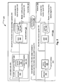
- FIG. 1 and FIG. 2 are diagrams illustrating various embodiments of communication systems, 100 and 200, respectively.
- this embodiment of a communication system 100 is a communication channel 199 that communicatively couples a communication device 110 (including a transmitter 112 having an encoder 114 and including a receiver 116 having a decoder 118) situated at one end of the communication channel 199 to another communication device 120 (including a transmitter 126 having an encoder 128 and including a receiver 122 having a decoder 124) at the other end of the communication channel 199.
- a communication device 110 including a transmitter 112 having an encoder 114 and including a receiver 116 having a decoder 118
- another communication device 120 including a transmitter 126 having an encoder 128 and including a receiver 122 having a decoder 124
- either of the communication devices 110 and 120 may only include a transmitter or a receiver.
- the communication channel 199 may be implemented (e.g., a satellite communication channel 130 using satellite dishes 132 and 134, a wireless communication channel 140 using towers 142 and 144 and/or local antennae 152 and 154, a wired communication channel 150, and/or a fiber-optic communication channel 160 using electrical to optical (E/O) interface 162 and optical to electrical (O/E) interface 164)).
- a satellite communication channel 130 using satellite dishes 132 and 134 e.g., a satellite communication channel 130 using satellite dishes 132 and 134, a wireless communication channel 140 using towers 142 and 144 and/or local antennae 152 and 154, a wired communication channel 150, and/or a fiber-optic communication channel 160 using electrical to optical (E/O) interface 162 and optical to electrical (O/E) interface 164)
- E/O electrical to optical
- O/E optical to electrical
- error correction and channel coding schemes are often employed.
- these error correction and channel coding schemes involve the use of an encoder at the transmitter and a decoder at the receiver.
- information bits 201 are provided to a transmitter 297 that is operable to perform encoding of these information bits 201 using an encoder and symbol mapper 220 (which may be viewed as being distinct functional blocks 222 and 224, respectively) thereby generating a sequence of discrete-valued modulation symbols 203 tat is provided to a transmit driver 230 that uses a DAC (Digital to Analog Converter) 232 to generate a continuous-time transmit signal 204 and a transmit filter 234 to generate a filtered, continuous-time transmit signal 205 that substantially comports with the communication channel 299.
- DAC Digital to Analog Converter
- continuous-time receive signal 206 is provided to an AFE (Analog Front End) 260 that includes a receive filter 262 (that generates a filtered, continuous-time receive signal 207) and an ADC (Analog to Digital Converter) 264 (that generates discrete-time receive signals 208).
- a metric generator 270 calculates symbol metrics 209 that are employed by a decoder 280 to make best estimates of the discrete-valued modulation symbols and information bits encoded therein 210.
- the communication devices of either of the previous embodiments can be implemented to include various decoding aspects described herein.
- several of the following Figures describe other and particular embodiments (some in more detail) that may be used to support the devices, systems, functionality and/or methods that may be implemented to perform decoding of LDPC codes signals.
- LDPC codes Before more details are provided below, a general description of LDPC codes is provided.
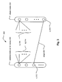
- FIG. 3 is a diagram illustrating an embodiment of an LDPC (Low Density Parity Check) code bipartite graph 300.
- an LDPC bipartite graph may also sometimes be referred to as a Tanner graph.
- An LDPC code may be viewed as being a code having a binary parity check matrix such that nearly all of the elements of the matrix have values of zeroes (e.g., the binary parity check matrix is sparse).
- LDPC codes were introduced by R. Gallager in [1] referenced below and by M. Luby et al. in [2] also referenced below.
- a regular LDPC code can be represented as a bipartite graph 300 by its parity check matrix with left side nodes representing variable of the code bits (or alternatively as the "variable nodes" (or “bit nodes”) 310 in a bit decoding approach to decoding LDPC coded signals), and the right side nodes representing check equations (or alternatively as the "check nodes” 320).
- the bipartite graph 300 of the LDPC code defined by H may be defined by N variable nodes (e.g., N bit nodes) and M check nodes.
- Every variable node of the N variable nodes 310 has exactly d v ( i ) edges (an example edge shown using reference numeral 330) connecting the bit node, ⁇ i 312, to one or more of the check nodes (within the M check nodes).
- the edge 310 is specifically shown as connecting from the bit node, v i 312, to the check node, c j 322.
- This number of d v edges (shown as d v 314) may be referred to as the degree of a variable node i.
- every check node of the M check nodes 1520 has exactly d c ( j ) edges (shown as d c 324) connecting this node to one or more of the variable nodes (or bit nodes) 310.
- This number of edges, d c may be referred to as the degree of the check node j.
- any codes that can be represented by a bipartite graph may be characterized as graph codes. It is also noted that an irregular LDPC code may also described using a bipartite graph. However, the degree of each set of nodes within an irregular LDPC code may be chosen according to some distribution. Therefore, for two different variable nodes, v i1 and v i2 of an irregular LDPC code,
- may not equal to
- the concept of irregular LDPC codes was originally introduced within M. Luby et al. in [2] referenced above.
- the parameters of an LDPC code can be defined by a degree of distribution, as described within M. Luby et al. in [2] referenced above and also within the following reference [3]:
- ⁇ i the fraction of edges emanating from variable nodes of degree i and let ⁇ i represent the fraction of edges emanating from check nodes of degree i.
- G F ( p m ) ⁇ 0 , ⁇ , ... , ⁇ p m ⁇ 1 ⁇ .
- G [ g 0 g 1 ⁇ g ⁇ ⁇ 3 1 0 0 g 0 ⁇ g ⁇ ⁇ 4 g ⁇ ⁇ 3 1 ]
- a weight ⁇ codeword e.g., c 0
- a weight ⁇ -1 codeword e.g., c 1
- GRS generalized Reed-Solomon
- the integer p can be any number between 1 to p m .
- Take a location set L ⁇ ⁇ i0 ,..., ⁇ i ⁇ -1 ⁇ .
- ⁇ ⁇ G F ( p m ) ⁇ ⁇ c 0 , 0 , c 0 , 1 , ... , c 0 , p m ⁇ 1 ⁇
- x ⁇ C 0 ⁇ , i 1 , ... , p m ⁇ 1
- L GF ( p m ) ⁇ ⁇ 0,1 ⁇ pm such that L ( ⁇ i )is a p m -vector and such that the i+ 1 is 1 and all other positions are 0.
- L (0) (10... 0)
- L( ⁇ ) (010...0)
- LDPC code has a bipartite graph having bit degree ⁇ and having check degree ⁇ .
- such an LDPC code is a regular LDPC code.
- LDPC codes may be referred to as RS-based LDPC codes or GRS-based regular LDPC codes. Since a RS code is a special case of the GRS code, the general term of GRS code is employed subsequently and may be viewed as including both any of the various RS codes as well as the GRS code.
- a novel approach is presented herein to construct a GRS-based irregular LDPC code by modifying a GRS-based regular LDPC code that has been constructed according to the principles of H in (EQ 9) above.
- the generation of the parity check matrix that corresponds to this GRS-based irregular LDPC code is performed by replacing some permutation matrices of the parity check matrix that corresponds to the GRS-based regular LDPC code constructed according to (EQ 9) above within to all 0 matrices; this process of replacing a permutation matrix with an all zero-valued matrix can be referred to as "puncturing". That is to say, at least one permutation matrix within the parity check matrix is replaced with a zero matrix (i.e., a matrix having all 0 valued entries).
- One design choice is which of the permutation matrices should be replaced by a zero matrix (i.e., a matrix having all 0 valued entries). There is wide latitude left to the designer to select which of the permutation matrices should be replaced by a zero matrix.
- FIG. 4 illustrates an embodiment of a method 400 for constructing a parity check matrix that corresponds to a GRS (Generalized Reed-Solomon)-based irregular LDPC (Low Density Parity Check) code.
- GRS Generalized Reed-Solomon
- LDPC Low Density Parity Check
- the method involves choosing a plurality of possible bit degree distributions for an LDPC code block.
- 3 different bit degrees in an LDPC code block e.g., in the irregular LDPC code context
- degree distributions that include other than 3 different types of bit degrees may also be employed without departing from the scope and spirit of the invention.
- Several of the embodiments described herein employ 3 different bit degree distributions
- the method then continues by selecting a bit degree distribution from among the plurality of possible bit degree distributions as shown in a block 420. It is noted that the selected bit degree distribution has a best performance threshold among the plurality of possible bit degree distributions. In some instances, the method may involve selecting the bit degree distribution from among the plurality of possible bit degree distributions based on performance as determined by the density evolution method, as shown in a block 422.
- bit degree distribution to be employed may be performed using a theoretical method such as density evolution method to get the degree distribution.
- density evolution method is described in detail in the following reference [3] (also identified above):
- a parity check matrix, H may be constructed to be a ⁇ p m ⁇ ⁇ p m matrix of the form as described with respect to (EQ 9) above.
- the largest bit degree of the to-be-constructed GRS-based irregular LDPC code is then ⁇ .
- a designed may also choose other degrees that are less than ⁇ , as well as their corresponding bit degree distribution based on some other theoretical method. The number of bits within the block having the same bit degree will then be the multiple of p m .
- 11 possible bit degree distributions are considered for the LDPC code block.
- the bit degree distribution, D3 is one of the best candidates.
- the density evolution method may be employed to select the bit degree distribution to be used to construct the GRS-based irregular LDPC code.
- the parity check matrix corresponding to the bit degree distribution, D3, may be denoted as H.
- This parity check matrix, H then contains 8 x 24 separate and distinct 81 x 81 sub-matrices (referred to as permutation matrices when not replaced by a zero matrix).
- the parity check matrix, H has 4 columns of 8 permutation matrices, 12 columns of 4 permutation matrices and 8 columns of 2 permutation matrices.
- the rest of the sub-matrices are all zero matrices (i.e., matrices having all 0 valued entries).
- 192 - 96 96 permutation matrices in the original regular LDPC code needs to be replaced by all zero matrices.
- the method then involves selecting a bit degree distribution from among the plurality of possible bit degree distributions as shown in a block 120.
- the selection of which permutation matrix or permutation matrices should be replaced by all zero matrices may include a wide variety of design considerations. For example, after constructing a number of different GRS-based irregular LDPC codes, consideration may be given to the performance of the various GRS-based irregular LDPC codes (e.g., selecting the one providing the best performance), the ease/difficulty of a decoder's implementation (e.g., the hardware implementation) to decode such a coded signal in a particular application, as well as other design considerations without departing from the scope and spirit of the invention. It is noted that determination of which GRS-based LDPC code provides the best performance may require a great deal of intensive simulations by a designer.
- the method then continues by partitioning a parity check matrix that corresponds to a GRS-based regular LDPC code into a plurality of partial-matrices (each having a corresponding bit degree) based on the selected bit degree distribution, as shown in a block 430.
- the number of partial-matrices corresponds to the number of bit degrees within the selected bit degree distribution.
- the parity check matrix, H may be decomposed into 3 separate partial-matrices.
- each of these partial-matrices has a corresponding bit degree.
- the partial-matrix, H 1 has a bit degree of 8
- the partial-matrix, H 2 has a bit degree of 4
- the partial-matrix, H 3 has a bit degree of 2.
- H 1 [ P 1 , 1 P 1 , 2 P 1 , 3 P 1 , 4 P 2 , 1 P 2 , 2 P 2 , 3 P 2 , 4 P 3 , 1 P 3 , 2 P 3 , 3 P 3 , 4 P 4 , 1 P 4 , 2 P 4 , 3 P 4 , 4 P 5 , 1 P 5 , 2 P 5 , 3 P 5 , 4 P 6 , 1 P 6 , 2 P 6 , 3 P 6 , 4 P 7 , 1 P 7 , 2 P 7 , 3 P 7 , 4 P 8 , 1 P 8 , 2 P 8 , 3 P 8 , 4 ] .
- This first partial-matrix, H 1 is a 648 ⁇ 423 matrix constructed by the individual permutation matrices, P ij , which are each 81 ⁇ 81 permutation matrices. It is noted that while many different values are employed in various examples within this disclosure, clearly many of these particular values described herein may be selected and modified by a designer of such a GRS-based irregular LDPC code to design an appropriate code for use in a particular application. In other words, these values are employed to assist the reader in understanding the various aspects of the invention, and a designer is free to employ other values to design a different GRS-based irregular LDPC code.
- the method continues by replacing at least one permutation matrix within at least one partial-matrix of the plurality of partial-matrices with a zero matrix (i.e., a matrix having all 0 valued entries) thereby generating a parity check matrix that corresponds to a GRS-based irregular LDPC code, as shown in a block 440.
- a zero matrix i.e., a matrix having all 0 valued entries
- H 2 1 [ P 1 , 5 P 1 , 8 P 1 , 9 P 1 , 12 P 1 , 13 P 1 , 16 P 2 , 5 P 2 , 8 P 2 , 9 P 2 , 12 P 2 , 13 P 2 , 16 P 3 , 5 P 3 , 6 P 3 , 9 P 3 , 10 P 3 , 13 P 4 , 13 P 4 , 5 P 4 , 6 P 4 , 9 P 4 , 10 P 4 , 13 P 4 , 14 P 5 , 6 P 5 , 7 P 5 , 10 P 5 , 11 P 5 , 14 P 5 , 15 P 6 , 6 P 6 , 7 P 6 , 10 P 6 , 11 P 6 , 14 P 6 , 15 P 7 , 7 P 7 , 8 P 7 , 11 P 7 , 12 P 7 , 15 P 7 , 16 P 5 , 5 , 5 , 16 P 5 , 5 P 1 , 8 P 1 , 9 P 1 , 12 P 1 , 13 P 1 ,
- This second modified partial-matrix, H 2 1 is a 648 x 972 matrix such that the each of the empty positions of the matrix represents an 81 ⁇ 81 zero matrix (e.g., all 81 ⁇ 81 entries therein being 0) and the remaining matrices, P i,j , are all corresponding permutation matrices.
- H 2 [ P 1 , 5 P 1 , 7 P 1 , 6 P 1 , 9 P 1 , 11 P 1 , 13 P 2 , 6 P 2 , 5 P 2 , 8 P 2 , 10 P 2 , 12 P 2 , 14 P 2 , 5 P 3 , 7 P 3 , 6 P 3 , 9 P 3 , 11 P 3 , 13 P 4 , 6 P 4 , 5 P 4 , 8 P 4 , 10 P 4 , 12 P 4 , 14 P 5 , 5 P 5 , 7 P 5 , 6 P 5 , 9 P 5 , 11 P 5 , 13 P 6 , 6 P 6 , 5 P 6 , 8 P 6 , 10 P 6 , 12 P 6 , 14 P 7 , 5 P 7 , 7 P 5 , 6 P 5 , 9 P 5 , 11 P 5 , 13 P 6 , 6 P 6 , 5 P 6 , 8 P 6 , 10 P 6 , 12 P 6 , 14 P 7 , 5 P 7 , 7 P
- This alternative embodiment of the modified second partial-matrix, H 2 2 is a 648 ⁇ 972 matrix such that the each of the empty positions of the matrix represents an 81 ⁇ 81 zero matrix (e.g., all 81 ⁇ 81 entries therein being 0) and the remaining matrices, P i,j , are all corresponding permutation matrices.
- H 3 1 [ P 1 , 17 P 1 , 18 P 2 , 18 P 2 , 19 P 3 , 19 P 3 , 20 P 4 , 20 P 4 , 21 P 5 , 21 P 5 , 22 P 6 , 22 P 6 , 23 P 7 , 23 P 7 , 24 P 8 , 17 P 8 , 24 ]
- This first embodiment of the modified third partial-matrix, H 3 1 is a 648 ⁇ 648 matrix such that the each of the empty positions of the matrix represents an 81 ⁇ 81 zero matrix (e.g., all 81 ⁇ 81 entries therein being 0) and the remaining matrices, P i,j , are all corresponding permutation matrices.
- H 3 2 [ P 1 , 17 P 1 , 24 P 2 , 17 P 2 , 18 P 3 , 18 P 3 , 19 P 4 , 19 P 4 , 20 P 5 , 20 P 5 , 21 P 6 , 21 P 6 , 22 P 7 , 22 P 7 , 23 P 8 , 23 P 8 , 24 ]
- This alternative embodiment of the modified third partial-matrix, H 3 2 is also a 648 x 648 matrix such that the each of the empty positions of the matrix represents an 81 x 81 zero matrix (e.g., all 81 x 81 entries therein being 0) and the remaining matrices, P i,j , are all corresponding permutation matrices.
- each of these partial matrices may modified thereby generating a parity check matrix that corresponds to a GRS-based irregular LDPC code.
- a designer has great latitude to select which of the permutation matrices are to be replaced by zero matrices.
- modified partial-matrices illustrate just some possible examples by which the parity check matrix may be generated.
- H ( 1 ) [ H 1 , H 2 1 , H 3 1 ]
- H ( 2 ) [ H 1 , H 2 1 , H 3 2 ]
- H ( 3 ) [ H 1 , H 2 2 , H 3 1 ]
- H ( 4 ) [ H 1 , H 2 1 , H 3 1 ]
- This GRS-based regular LDPC code (LDPC 0 ) code has rate 0.67.
- This GRS-based irregular LDPC code ( LDPC 1 ) has code rate 0.667.
- This GRS-based irregular LDPC code ( LDPC 2 ) also has code rate 0.667.
- the following diagram shows an embodiment of how one GRS-based irregular LDPC code may be selected during a design approach from among a plurality of GRS-based irregular LDPC codes.
- FIG. 5 illustrates an embodiment of a method 500 for selecting a GRS-based irregular LDPC code.
- This method involves generating a plurality of parity check matrices that corresponds to a plurality of GRS-based irregular LDPC codes (e.g., a plurality of variations of parity check matrices), as shown in a block 510.
- the various embodiments described above may be employed to generate the plurality of parity check matrices that corresponds to a plurality of GRS-based irregular LDPC codes.
- the method involves determining the performance of each GRS-based irregular LDPC code, having a corresponding parity check matrix, of the plurality of GRS-based irregular LDPC codes (e.g., in terms of BER and/or BLER as a function of SNR).
- the method then involves selecting a GRS-based irregular LDPC code, having a corresponding parity check matrix, from among the plurality of GRS-based irregular LDPC codes having a best performance, as shown in a block 530. In some instances, this best performance may be viewed in terms of which GRS-based irregular LDPC code has the lowest error floor in terms of BER/BLER as a function of SNR.
- the selection of which of the GRS-based irregular LDPC codes should be selected may include additionally or alternatively considering the ease/difficulty of decoder implementation given the particular application, as shown in a block 532.
- FIG. 6 illustrates an embodiment 600 of generation of a parity check matrix that corresponds to a GRS-based irregular LDPC code using a parity check matrix that corresponds to a GRS-based regular LDPC code. This diagram may assist the reader in understanding the manner by which the parity check matrix is constructed.
- a parity check matrix, H reg that corresponds to a GRS-based regular LDPC code, as indicated by reference numeral 610, is decomposed into a plurality of partial-matrices (shown as partial matrix, H 1 621, partial matrix, H 2 622, partial matrix, H 3 623, and ... partial matrix, H n 629).
- the number of partial-matrices into which the parity check matrix, H reg , that corresponds to a GRS-based regular LDPC code is decomposed may be selected by the designer of the GRS-based irregular LDPC code.
- partial-matrices e.g., partial matrix, H 3 623
- this modified partial-matrix is referred to as partial-matrix, ( H 3 ) ' 633.
- any one of the partial-matrices may be modified; the partial-matrix, H 3 623 being modified into the partial-matrix, ( H 3 )' 633 is shown in this diagram just as one possible design choice.
- other of the partial-matrices may alternatively be modified.
- more than one of the partial-matrices may be modified without departing from the scope and spirit of the invention.
- H irr a parity check matrix that corresponds to a GRS-based irregular LDPC code, as indicated by reference numeral 640.
- d min The minimum distance, d min , of such a GRS-based irregular LDPC code is provided as follows: d min ⁇ ⁇ ⁇ + 2 even ⁇ ⁇ + 1 odd ⁇
- the minimum distance, d min of such the GRS-based irregular LDPC code is the same minimum distance, d min , of the GRS-based regular LDPC code that is used to generate the GRS-based irregular LDPC code.
- both of the GRS-based irregular LDPC code and the GRS-based regular LDPC code has the same minimum distance, d min .
- each of the GRS-based irregular LDPC code and the GRS-based regular LDPC code has no loops less than size of 6. There are no size 4 loops in either of the LDPC bipartite graphs that correspond to either of the GRS-based irregular LDPC code and the GRS-based regular LDPC code.
- the corresponding LDPC bipartite graph for such a GRS-based irregular LDPC code will have no cycle (or loop) that is less than or equal to 4.
- the minimum cycle (or loop) of the corresponding LDPC bipartite graph would then be 6. That is to say, each loop of an LDPC bipartite graph that corresponds to the GRS-based irregular LDPC code is at least a size of 6; the code should have no size 4 loops.
- the GRS-based irregular LDPC code is in fact an "irregular" LDPC code, it will provide for better performance than that of a "regular" LDPC code.
- BLER Block Error Rate
- E b /N o ratio of energy per bit E b to the Spectral Noise Density N o
- BLER Block Error Rate
- E b /N o ratio of energy per bit E b to the Spectral Noise Density N o
- performance may be viewed in terms of BER (Bit Error Rate) vs. E b /N o .
- This term E b /N o is the measure of SNR (Signal to Noise Ratio) for a digital communication system.
- the BLER may be determined for any given E b /N o (or SNR) thereby providing a relatively concise representation of the performance of the decoding approach.
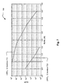
- FIG. 7 illustrates an embodiment of a performance comparison 700 between a GRS-based regular LDPC code (LDPC 0 ) (shown by reference numeral 710) and a second GRS-based irregular LDPC code (LDPC 2 ) (shown by reference numeral 720) on an AWGN (Additive White Gaussian Noise) communication channel.
- LDPC 0 GRS-based regular LDPC code
- LDPC 2 GRS-based irregular LDPC code
- AWGN Additional White Gaussian Noise
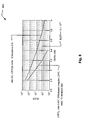
- FIG. 8 illustrates an embodiment of a performance comparison 800 between a GRS-based irregular LDPC code (LDPC 2 ) (shown by reference numeral 820) and an alternative LDPC code, LDPC(a) (shown using reference numeral 810), on an AWGN communication channel.
- LDPC 2 GRS-based irregular LDPC code
- LDPC(a) alternative LDPC code
- the LDPC code, LDPC 2 depicted in each of FIG. 7 and FIG. 8 has the corresponding parity check matrix of EQ (12) as provided above. Again, this GRS-based irregular LDPC code ( LDPC 2 ) has code rate 0.667.
- This diagram compares codes LDPC 2 to a rate 2/3 code that is depicted by LDPC(a).
- This rate 2/3 code (LDPC(a)) is provided by the reference [4] cited below.
- the WWiSE is the WWiSE (World Wide Spectrum Efficiency) is an alliance of companies and entities developing a proposal for the IEEE 802.11n Wireless LAN Standard. More information related to the WWiSE may be found publicly at the following Internet address: "http://www.wwise.org/"
- the Rayleigh fading communication channel is considered and the modulation is 64 QAM (Quadrature Amplitude Modulation) with the mapping given in IEEE 802.11a standard as referenced below in [5]:
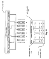
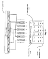
- FIG. 9, FIG. 10, FIG. 11, FIG. 12, and FIG. 13 illustrate embodiments of bit to symbol interleaving.
- FIG. 9 shows embodiment 900 (interleave 2, shown as (II 2));
- FIG. 10 shows embodiment 1000 (interleave 3, shown as (II 3));
- FIG. 11 shows embodiment 1100 (interleave 4, shown as (II 4));
- FIG. 12 shows embodiment 1200 (interleave 5, shown as ( ⁇ 4));
- FIG. 13 shows embodiment 1300 (interleave 6, shown as ( ⁇ 6); respectively, of various embodiments of bit to symbol interleaving.
- Each of these is shown as being a 6-bit symbol interleave that operates on an LDPC block of encoded bits (e.g., an LDPC codeword).
- any other number (i.e., n) of columns may be employed to perform a bit to n -bit interleave as well without departing from the scope and spirit of the invention.
- an LDPC block 909 is received and may be viewed as being partitioned or divided into a plurality of parts.
- the LDPC block 909 is divided into part 0 910, part 1 911, part 2 912, part 3 913, part 4 914, and part 5 915. Each of these parts is provided to a corresponding column.
- Each of the parts is provided to a plurality of column as indicated in the diagram.
- the 6 bit labels to be symbol mapped (as indicated by reference numeral 919) that are pulled out from the columns are as follows (MSB (Most Significant Bit) on left ... LSB (Least Significant Bit) on right): 1 st 6 bit label: C 0 C k C 2k C 3k C 4k C 5k 2 nd 6 bit label: C 1 C k+1 C 2k+1 C 3k+1 C 4+1 C 5k+1 ... nth 6 bit label: C k-1 C 2k-1 C 3k-1 C 4k-1 C 5k-1 C 6k-1
- Each of the parts that is provided to each of the corresponding columns has k bits.
- the total number of bits of the LDPC block 909 is 6k.
- bits (c 5k-1 , ..., c 4k+1 , C 4k ) and the LSB bits (c 6k-1 , ..., c 5k+1 , C 5k ) are redundancy bits as selected from the LDPC block 909 as indicated by the reference numerals 932 and 931, respectively.
- an LDPC block 1009 is received and may be viewed as being partitioned or divided into a plurality of parts.
- the LDPC block 1009 is divided into part 0 1010, part 1 1011, part 2 1012, part 3 1013, part 4 1014, and part 5 1015. Each of these parts is provided to a corresponding column.
- Each of the parts is provided to a plurality of columns in an analogous fashion as the previous embodiment. However, the columns are permuted as indicated in the diagram.
- the 6 bit labels to be symbol mapped (as indicated by reference numeral 1019) that are pulled out from the columns are as follows (MSB on left ... LSB on right): 1 st 6 bit label: C 4k C 2k C 0 C 5k C 3k C k 2 nd 6 bit label: C 4k+1 C 2k + 1 C 1 C 5k+1 C 3k+1 C k+1 nth 6 bit label: C 5k-1 C 3k-1 C k-1 C 6k-1 C 4k-1 C 2k-1
- Each of the parts that is provided to each of the corresponding columns has k bits.
- the total number of bits of the LDPC block 1009 is 6k.
- MSB east Significant Bit
- MSB bits c 5k-1 , ..., c 4k+1 , c 4k
- bits c 6k-1 , ..., c 5k+1 , c 5k
- LDPC block 1009 as indicated by the reference numerals 1032 and 1031, respectively.
- an LDPC block 1109 is received and may be viewed as being partitioned or divided into a plurality of parts.
- the LDPC block 1109 is divided into part 0 1110, part 1 1111, part 2 1112, part 3 1113, part 4 1114, and part 5 1115. Each of these parts is provided to a corresponding column.
- Each of the parts is provided to a plurality of columns in an analogous fashion as the previous embodiment. However, the columns are permuted as indicated in the diagram.
- the 6 bit labels to be symbol mapped (as indicated by reference numeral 1119) that are pulled out from the columns are as follows (MSB on left ... LSB on right): 1 st 6 bit label: C 3k C 0 C 4k C 2k C k C 5k 2 nd 6 bit label: C 3k+1 C 1 C 4k+1 C 2k+1 C k+1 C 5k+1 nth 6 bit label: C 4k-1 C k-1 C 5k-1 C 3k-1 C 2k-1 C 6k-1
- Each of the parts that is provided to each of the corresponding columns has k bits.
- the total number of bits of the LDPC block 1109 is 6k.
- the bits (c 5k-1 , ..., c 4k+1 , c 4k ) and the LSB bits (c 6k-1 , ..., c 5k+1, c 5k ) are redundancy bits as selected from the LDPC block 1109 as indicated by the reference numerals 1132 and 1131, respectively.
- an LDPC block 1209 is received and may be viewed as being partitioned or divided into a plurality of parts.
- the LDPC block 1209 is divided into part 0 1210, part 1 1211, part 2 1212, part 3 1213, part 4 1214, and part 5 1215. Each of these parts is provided to a corresponding column.
- Each of the parts is provided to a plurality of columns in an analogous fashion as the previous embodiment. However, the columns are permuted as indicated in the diagram.
- the 6 bit labels to be symbol mapped (as indicated by reference numeral 1219) that are pulled out from the columns are as follows (MSB on left ... LSB on right): 1 st 6 bit label: c 2k c 0 c 4k c k c 3k c 5k 2 nd 6 bit label: c 2k + 1 c 1 c 4k+1 c k+1 c 3k+1 c 5k+1 nth 6 bit label: c 3k-1 c k-1 c 5k-1 c 2k-1 c 4k-1 c 6k-1
- Each of the parts that is provided to each of the corresponding columns has k bits.
- the total number of bits of the LDPC block 1209 is 6k.
- the bits (c 5k-1 , ..., c 4k+1 , c 4k ) and the LSB bits (c 6k-1 , ..., c 5k+1 , c 5k ) are redundancy bits as selected from the LDPC block 1209 as indicated by the reference numerals 1232 and 1231, respectively.
- an LDPC block 1309 is received and may be viewed as being partitioned or divided into a plurality of parts.
- the LDPC block 1309 is divided into part 0 1310, part 1 1311, part 2 1312, part 3 1313, part 4 1314, and part 5 1315. Each of these parts is provided to a corresponding column.
- Each of the parts is provided to a plurality of columns in an analogous fashion as the previous embodiment. However, the columns are permuted as indicated in the diagram.
- the 6 bit labels to be symbol mapped (as indicated by reference numeral 1319) that are pulled out from the columns are as follows (MSB on left ... LSB on right): 1 st 6 bit label: c 0 c 2k c 4k c k c 3k c 5k 2 nd 6 bit label: c 1 c 2k+1 c 4k+1 c k+1 c 3k+1 c 5k+1 nth 6 bit label: c k-1 c 3k-1 c 5k-1 c 2k-1 c 4k-1 c 6k-1
- Each of the parts that is provided to each of the corresponding columns has k bits.
- the total number of bits of the LDPC block 1309 is 6k.
- the bits (c 5k-1 , ..., c 4k+1 , c 4k ) and the LSB bits (c 6k-1 , ..., c 5k+1 , c 5k ) are redundancy bits as selected from the LDPC block 1309 as indicated by the reference numerals 1332 and 1331, respectively.
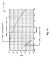
- FIG. 14 illustrates an embodiment of a performance comparison 1400 between a GRS-based regular LDPC code (LDPC 0 ) (shown by reference numeral 1405), a first GRS-based irregular LDPC code (LDPC 1 ) (shown by reference numeral 1410), and a second GRS-based irregular LDPC code (LDPC 2 ) (shown by reference numeral 1420) on a Rayleigh fading communication channel.
- LDPC 0 GRS-based regular LDPC code
- LDPC 1 shown by reference numeral 1410
- LDPC 2 second GRS-based irregular LDPC code
- This GRS-based regular LDPC code ( LDPC 0 ) code has rate 0.67.
- This GRS-based irregular LDPC code ( LDPC 1 ) has code rate 0.667.
- This GRS-based irregular LDPC code ( LDPC 2 ) also has code rate 0.667.
- FIG. 15 illustrates an embodiment of a performance comparison 1500 between a first GRS-based irregular LDPC code (LDPC 1 ) (shown using reference numeral 1510), a second GRS-based irregular LDPC code (LDPC 2 ) (shown using reference numeral 1520), and an alternative LDPC code, LDPC(b) (shown using reference numeral 1505), on a communication channel.
- LDPC 1 first GRS-based irregular LDPC code
- LDPC 2 shown using reference numeral 1520
- LDPC(b) shown using reference numeral 1505
- This embodiment compares the codes LDPC, 1510 and LDPC 2 1520 to the rate 2/3 code, LDPC(b) 1505. That code, LDPC(b) 1505, has the same code length as 1944 and is also irregular. With the bit to symbol interleave that is provided in Fig. 9, the corresponding performances are given in Fig. 15.
- the GRS-based irregular codes constructed herein give 1 dB performance improvement.
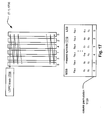
- FIG. 16 and FIG. 17 illustrate alternative embodiments of bit to symbol interleaving.
- FIG. 16 and FIG. 17 illustrate embodiment 1600 (interleave 0, shown as ( ⁇ 0)), and embodiment 1700 (interleave 1, shown as ( ⁇ 1)), respectively, of bit to symbol interleaving.
- each of these is shown as being a 6-bit symbol interleave that operates on an LDPC block of encoded bits (e.g., an LDPC codeword).
- any other number (i.e., n) of columns may be employed to perform a bit to n-bit interleave as well without departing from the scope and spirit of the invention.
- an LDPC block 1609 is provided directly to each of a plurality of columns. Rather than put each of a plurality of parts of the LDPC block 1609 into corresponding columns (as done in some of the previous embodiments), a first bit of the LDPC block 1609 is provided to a first column, a second bit of the LDPC block is provided to a second column, a third bit of the LDPC block is provided to a third column, and so on. As can be seen, the order of the columns is not permuted (0 1 2 3 4 5) , as indicated by the reference numeral 1629. Depending on the symbol size employed (e.g., n bit symbol size), then the n +1 symbol is provided to the first column in a wrapping around procedure as depicted in the diagram.
- the symbol size employed e.g., n bit symbol size
- the 6 bit labels to be symbol mapped (as indicated by reference numeral 1619) that are pulled out from the columns are as follows (MSB on left ... LSB on right): 1 st 6 bit label: c 0 c 1 c 2 c 3 c 4 c 5 2 nd 6 bit label: c 6 c 7 c 8 c 9 c 10 c 11 ... nth 6 bit label: C 6k-6 C 6k-5 C 6k-4 C 6k-3 C 6k-2 C 6k-1
- the total number of bits of the LDPC block 1609 is 6k. As can be seen with respect to the LSB and MSB of the bits that are of the mapped pulled out from the rows, there is no column permutation with respect to the columns into which the parts are partitioned as indicated by the reference numeral 1629.
- an LDPC block 1709 is provided directly to each of a plurality of columns. Rather than put each of a plurality of parts of the LDPC block 1609 into corresponding columns (as done in some of the previous embodiments), a first bit of the LDPC block 1609 is provided to a first column, a second bit of the LDPC block is provided to a second column, a third bit of the LDPC block is provided to a third column, and so on. As can be seen, the order of the columns is in fact permuted (0 2 4 1 3 5), as indicated by the reference numeral 1729. Depending on the symbol size employed (e.g., n bit symbol size), then the n +1 symbol is provided to the first column in a wrapping around procedure as depicted in the diagram.
- the symbol size employed e.g., n bit symbol size
- the 6 bit labels to be symbol mapped (as indicated by reference numeral 1719) that are pulled out from the columns are as follows (MSB on left ... LSB on right): 1 st 6 bit label: c 0 c 2 c 4 c 1 c 3 c 5 2 nd 6 bit label: c 5 c 7 c 9 c 6 c 8 c 10 nth 6 bit label: C 6k-6 C 6k-4 C 6k-2 C 6k-5 C 6k-3 C 6k-1
- the total number of bits of the LDPC block 1709 is 6k.
- the LSB and MSB of the bits that are of the mapped pulled out from the rows there is in fact a column permutation with respect to the columns into which the parts are partitioned as indicated by the reference numeral 1729.
- Those embodiments (900, 1000, 1100, 1200, and 1300) require a bit of memory management and incur some latency when compared to the embodiments 1600 and 1700.
- LDPC blocks e.g., having different total numbers of bits
- symbols having other numbers of bits e.g., labels for symbols having n bits and n corresponding columns
- a designer is provided wide latitude is selecting the LDPC block size and type as well as the manner of bit to symbol interleaving without departing from the scope and spirit of the invention.
- codes LDPC 1 1210 and LDPC 2 1220 out perform LDPC(b) 1205 by approximately 0.5 to 0.8 dB.
- the following four diagrams show the performance of 4 different GRS-based irregular LDPC codes to each of 4 alternative LDPC codes, namely, LDPC(c) (1944, 972), LDPC(d) (1944, 1296), LDPC(e) (1944, 487), and LDPC(f) (1944, 1620).
- Each of these 4 different GRS-based irregular LDPC codes designed according to the novel approach presented herein, has a corresponding low parity check matrix; these low density parity check matrices are provided in the APPENDIX.
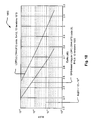
- FIG. 18 illustrates an embodiment of a performance comparison 1800 between a GRS-based irregular LDPC (1944, 973) code (1) (shown by reference numeral 1820) and a first code, LDPC(c) (1944, 972) (shown by reference numeral 1810), on a communication channel.
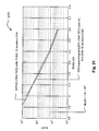
- FIG. 19 illustrates an embodiment of a performance comparison 1900 between a GRS-based irregular LDPC (1944, 1297) code (2) (shown by reference numeral 1920) and a second code, LDPC(d) (1944, 1296) (shown by reference numeral 1910), on a communication channel.
- a GRS-based irregular LDPC (1944, 1297) code (2) shown by reference numeral 1920
- LDPC(d) (1944, 1296) shown by reference numeral 1910
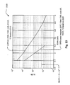
- FIG. 20 illustrates an embodiment of a performance comparison 2000 between a GRS-based irregular LDPC (1944, 487) code (3) (shown by reference numeral 2020) and a third code, LDPC(e) (1944, 486) (shown by reference numeral 2010), on a communication channel.
- a GRS-based irregular LDPC (1944, 487) code (3) shown by reference numeral 2020
- LDPC(e) (1944, 486) shown by reference numeral 2010
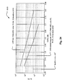
- FIG. 21 illustrates an embodiment of a performance comparison 2100 between a GRS-based irregular LDPC (1944, 1621) code (4) (shown by reference numeral 2120) and a fourth code, LDPC(t) (1944, 1620) (shown by reference numeral 2110), on a communication channel.
- a GRS-based irregular LDPC (1944, 1621) code (4) shown by reference numeral 2120
- LDPC(t) (1944, 1620) shown by reference numeral 2110
- FIG. 22A illustrates an embodiment of a method 2200 for generating an LDPC coded signal.
- This method 2200 involves constructing a generator matrix that corresponds to a parity check matrix of a corresponding GRS-based irregular LDPC code, as shown in a block 2210. When provided any parity check matrix that corresponds to an LDPC code, a corresponding generator matrix may be constructed.
- the method 2200 then involves encoding at least one information bit using the generator matrix thereby generating at least one LDPC codeword of an LDPC coded signal, as shown in a block 2220. This encoding operation may be viewed as taking place in an encoder at a transmitter end of a communication channel.
- the decoding of the LDPC coded signal may then be performed using the parity check matrix that is used to construct the generator matrix.
- Any of a number of hardware devices e.g., transmitters, transceivers, encoders, etc.
- transmitters, transceivers, encoders, etc. that include this encoding functionality may be implemented to perform these operations in any of a wide variety of communication system types.
- FIG. 22B illustrates an embodiment of a method 2205 for decoding an LDPC coded signal.
- This method 2205 may be viewed as receiving an LDPC coded signal, as shown in a block 2215. Then, the method 2205 may be viewed as decoding an LDPC coded signal, that has been encoded using a GRS-based irregular LDPC code, using a parity check matrix that corresponds to the GRS-based irregular LDPC code thereby making a best estimate of at least one information bit encoded within the LDPC coded signal, as shown in a block 2225. From some perspectives, this decoding operation may be viewed as being performed in a decoder located at a receiver end of a communication channel. Any of a number of hardware devices (e.g., receivers, transceivers, decoders, etc.) that include this decoding functionality may be implemented to perform these operations in any of a wide variety of communication system types.
- hardware devices e.g., receivers, transceivers,
- parity check matrix that corresponds to a GRS-based irregular LDPC code may take following form, where P is an n x n (e.g., 81 ⁇ 81 in one embodiment) permutation matrix.
- P [ 1 0 0 0 1 0 0 0 1 ]
- P [ 1 0 0 0 0 1 0 1 0 ] .
- each of the permutation matrices, P, and the zero matrices, x are 81 X 81 matrices when implemented within an LDPC code having a block length of 1944.
- One 1 st possible code structure is based on a parity check matrix, H, that corresponds to a GRS-based irregular LDPC code, for a code rate of 973/1944(>1/2), which may be approximated as being a code rate of 0.5.
- a 2 nd possible code structure is based on a parity check matrix, H, that corresponds to a GRS-based irregular LDPC code, for a code rate of 2/3, which may be approximated as being a code rate of 0.667.
- H a parity check matrix
- H a [ P P P P P x P x P x P x P x P x P x P x P x P x P x P x P x P x P x P x P x P x P x P x P x P x P x P x P x P x P x P x P x P x P x P x P x P x P x P x P x P ]
- H b [
- a 3 rd possible code structure is based on a parity check matrix, H, that corresponds to a GRS-based irregular LDPC code, for a code rate of 3/4.
- a 4 th possible code structure is based on a parity check matrix, H, that corresponds to a GRS-based irregular LDPC code, for a code rate of 5/6, which may be approximated as being a code rate of 0.833.
- H a [ P P P P P P P P P P P P P P P P P P P P P P P P P P P P P P P P P P P P ]
- H b [ P P P P P P P P P P P x x P P P P P P P P P P P P P P P P x P P P P P P P P x x P P ]
- the GRS-based irregular LDPC coded constructed according to each of these possible parity check matrices achieve better BLER performance at all rates and SNRs. In addition, these codes have lower error floors.
- Each of these GRS-based irregular LDPC codes is simulated down to a BLER of 1.5 x 10- 5 , which is appropriate for aggregated frames of 8192 bytes.
- FIG. 23 illustrates an embodiment of a performance comparison 2300 between a GRS-based irregular LDPC (1944, 1296) code (5) (shown using reference numeral 2320) and the second code, LDPC(d) (1944, 1296) (shown using reference numeral 2310), on a communication channel.
- a GRS-based irregular LDPC (1944, 1296) code (5) shown using reference numeral 2320
- LDPC(d) (1944, 1296) shown using reference numeral 2310
- FIG. 24 illustrates an embodiment of a performance comparison 2400 between a GRS-based irregular LDPC (1944, 486) code (6) (shown using reference numeral 2420) and the third code, LDPC(e) (1944, 486) (shown using reference numeral 2410), on a communication channel.
- a GRS-based irregular LDPC (1944, 486) code (6) shown using reference numeral 2420
- the third code, LDPC(e) (1944, 486) shown using reference numeral 2410
- FIG. 25 illustrates an embodiment of a performance comparison 2500 between a GRS-based irregular LDPC (1944, 1620) code (7) (shown using reference numeral 2520) and the fourth code, LDPC(f) (1944, 1620) (shown using reference numeral 2510), on a communication channel.
- FIG. 26 illustrates an embodiment of a performance comparison 2600 between a first GRS-based irregular LDPC code (LDPC 1 ), a second GRS-based irregular LDPC code (LDPC 2 ), and an alternative LDPC code, LDPC(b), using different types of bit to symbol interleaving, on a communication channel.
- This communication channel is a Rayleigh fading communication channel, and the modulation employed is 64 QAM.
- the LDPC block size of each of these codes (LDPC 1 and LDPC 2 ) is 1944, and the number of decoding iterations for each of these performance curves is 12.
- the alternative LDPC code, LDPC(b) has a code rate of 2/3, a code length of 1944 and is also an irregular LDPC code.
- This GRS-based irregular LDPC code ( LDPC 1 ) has code rate 0.667.
- This GRS-based irregular LDPC code ( LDPC 2 ) also has code rate 0.667.
- bit to symbol interleaving Several different types of bit to symbol interleaving are employed; some of these bit to symbol interleaves are depicted above within the FIG. 9 ( ⁇ 2), FIG. 10 ( ⁇ 3), FIG. 11 ( ⁇ 4), FIG. 12 ( ⁇ 5), FIG. 13 ( ⁇ 6), FIG. 16 ( ⁇ 0), and FIG. 17 ( ⁇ 1), respectively.
- FIG. 9 ⁇ 2
- FIG. 10 ⁇ 3
- FIG. 11 ⁇ 4
- FIG. 12 ⁇ 5
- FIG. 13 ⁇ 6
- FIG. 16 ⁇ 0
- FIG. 17 Several different types of bit to symbol interleaving are employed; some of these bit to symbol interleaves are depicted above within the FIG. 9 ( ⁇ 2), FIG. 10 ( ⁇ 3), FIG. 11 ( ⁇ 4), FIG. 12 ( ⁇ 5), FIG. 13 ( ⁇ 6), FIG. 16 ( ⁇ 0), and FIG. 17 ( ⁇ 1), respectively.
- alternative permuting of the columns employed therein could also be performed without departing from the scope and spirit of the invention.
- LDPC 1 GRS-based irregular LDPC code
- ⁇ 1 bit to symbol interleaving
- ⁇ 2 bit to symbol interleaving
- GRS-based irregular LDPC code (LDPC 2 ) is depicted using bit to symbol interleaving ( ⁇ 1) (shown using reference numeral 2621), bit to symbol interleaving ( ⁇ 2) (shown using reference numeral 2622), bit to symbol interleaving ( ⁇ 4) (shown using reference numeral 2624), bit to symbol interleaving ( ⁇ 5) (shown using reference numeral 2625), and bit to symbol interleaving ( ⁇ 6) (shown using reference numeral 2626).
- LDPC(b) The performance of alternative LDPC code, LDPC(b), is depicted using bit to symbol interleaving ( ⁇ 0) (shown using reference numeral 2630), bit to symbol interleaving ( ⁇ 1) (shown using reference numeral 2631), bit to symbol interleaving ( ⁇ 2) (shown using reference numeral 2632), bit to symbol interleaving ( ⁇ 3) (shown using reference numeral 2633), and bit to symbol interleaving ( ⁇ 6) (shown using reference numeral 2636).
- bit to symbol interleaving ⁇ 0
- ⁇ 1 bit to symbol interleaving
- ⁇ 2 bit to symbol interleaving
- ⁇ 3 bit to symbol interleaving
- ⁇ 6 bit to symbol interleaving
- each of the GRS-based irregular LDPC code (LDPC 1 ) and the GRS-based irregular LDPC code (LDPC 2 ) outperforms the alternative LDPC code, LDPC(b), by approximately 0.8 dB.
- the GRS-based irregular LDPC codes that have been constructed according to the approach provided herein out perform other codes in terms of providing for lower error floors in terms of BLER as a function of SNR.
- bit to symbol interleaving can provide for a significant increase in performance for each of the various LDPC codes whose performance is compared here. This principle may be extended to a wide variety of LDPC codes including those not specifically presented herein. There are many approaches by which the bit to symbol interleaving of an LDPC block may be performed.
- One possible approach seeks to correspond those LDPC coded bits of the LDPC block that have higher coding strength (i.e., higher bit degree thereby indicating relatively more edges connected between those bit nodes and corresponding check nodes) to the LSBs of an n-bit label that is to be symbol mapped according to a modulation (having a constellation shape and corresponding mapping).
- This approach also seeks to correspond those LDPC coded bits of the LDPC block that have lower coding strength (i.e., lower bit degree thereby indicating relatively fewer edges connected between those bit nodes and corresponding check nodes) to the MSBs of an n-bit label that is to be symbol mapped according to a modulation (having a constellation shape and corresponding mapping).
- This approach seeks to align those LDPC coded bits (of the LDPC block) that have relatively higher coding strength to the relatively weak bit locations within the n-bit label (i.e., LSBs), and to align those LDPC coded bits (of the LDPC block) that have relatively lower coding strength to the relatively strong bit locations within the n-bit label (i.e., MSBs).
- This approach can be referred to as "strong to weak and weak to strong”.
- Another possible approach seeks to correspond those LDPC coded bits of the LDPC block that have higher coding strength (i.e., higher bit degree thereby indicating relatively more edges connected between those bit nodes and corresponding check nodes) to the MSBs of an n-bit label that is to be symbol mapped according to a modulation (having a constellation shape and corresponding mapping).
- This approach also seeks to correspond those LDPC coded bits of the LDPC block that have lower coding strength (i.e., lower bit degree thereby indicating relatively fewer edges connected between those bit nodes and corresponding check nodes) to the LSBs of an n-bit label that is to be symbol mapped according to a modulation (having a constellation shape and corresponding mapping).
- This approach seeks to align those LDPC coded bits (of the LDPC block) that have relatively higher coding strength to the relatively strong bit locations within the n-bit label (i.e., MSBs), and to align those LDPC coded bits (of the LDPC block) that have relatively lower coding strength to the relatively weak bit locations within the n-bit label (i.e., LSBs).
- This approach can be referred to as "strong to strong and weak to weak".
- the first 3 bits (starting at the MSB) can be considering as an in-phase component
- the last 3 bits (ending at the MSB) can be considering as a quadrature-phase component as in an I, Q (In-phase, Quadrature) implementation.
- each of these 3 bit groups can also be appropriately interleaved such that these 3 bit groups may also be mapped according to either of the "strong to weak and weak to strong” or the “strong to strong and weak to weak" approaches described above.
- both of the in-phase component (MSB and next 2 bits) and the quadrature-component (2 bits before LSB and LSB) can be mapped according to the "strong to weak and weak to strong” approach.
- both of the in-phase component (MSB and next 2 bits) and the quadrature-component (2 bits before LSB and LSB) can be mapped according to the "strong to strong and weak to weak" approach.
- the in-phase component (MSB and next 2 bits) can be can be mapped according to the "strong to weak and weak to strong” approach, and the quadrature-component (2 bits before LSB and LSB) can be mapped according to the "strong to strong and weak to weak” approach.
- the in-phase component (MSB and next 2 bits) can be can be mapped according to the "strong to strong and weak to weak” approach, and the quadrature-component (2 bits before LSB and LSB) can be mapped according to the "strong to weak and weak to strong” approach.
- the best performance is a function of both the coding selected (e.g., the GRS-based irregular LDPC code selected) as well as the bit to symbol interleave selected.
- the coding selected e.g., the GRS-based irregular LDPC code selected
- bit to symbol interleave selected e.g., the bit to symbol interleave selected.
Landscapes
- Physics & Mathematics (AREA)
- Probability & Statistics with Applications (AREA)
- Engineering & Computer Science (AREA)
- Theoretical Computer Science (AREA)
- Mathematical Physics (AREA)
- Error Detection And Correction (AREA)
Abstract
Description
- The present U.S. Utility Patent Application claims priority pursuant to 35 U.S.C. § 119(e) to the following U.S. Provisional Patent Applications which are hereby incorporated herein by reference in their entirety and made part of the present U.S. Utility Patent Application for all purposes:
- 1. U.S. Provisional Application Serial No. 60/642,689, entitled "Construction of LDPC (Low Density Parity Check) codes using generalized RS (Reed-Solomon) code," (Attorney Docket No. BP4008.2), filed Monday, January 10, 2005 (01/10/2005), pending.
- 2. U.S. Provisional Application Serial No. 60/674,084, entitled "Construction of Irregular LDPC (Low Density Parity Check) codes using RS (Reed-Solomon) codes or GRS (Generalized Reed-Solomon) code," (Attorney Docket No. BP4611), filed Friday, April 22, 2005 (04/22/2005), pending.
- 3. U.S. Provisional Application Serial No. 60/675,346, entitled "Construction of Irregular LDPC (Low Density Parity Check) codes using RS (Reed-Solomon) codes or GRS (Generalized Reed-Solomon) code," (Attorney Docket No. BP4611.1), filed Wednesday, April 27, 2005 (04/27/2005), pending.
- The following U.S. Utility Patent Application is hereby incorporated herein by reference in its entirety and made part of the present U.S. Utility Patent Application for all purposes:
- 1. U.S. Utility Patent Application Serial No. 11/190,333, entitled "Construction of LDPC (Low Density Parity Check) codes using GRS (Generalized Reed-Solomon) code," (Attorney Docket No. BP4372), filed Wednesday, July 27, 2005 (07/27/2005), pending.
- The invention relates generally to communication systems; and, more particularly, it relates to encoding and/or decoding of information within such communication systems.
- Data communication systems have been under continual development for many years. One such type of communication system that has been of significant interest lately is a communication system that employs iterative error correction codes. Of particular interest is a communication system that employs LDPC (Low Density Parity Check) code. Communications systems with iterative codes are often able to achieve lower bit error rates (BER) than alternative codes for a given signal to noise ratio (SNR).
- A continual and primary directive in this area of development has been to try continually to lower the SNR required to achieve a given BER within a communication system. The ideal goal has been to try to reach Shannon's limit in a communication channel. Shannon's limit may be viewed as being the data rate to be used in a communication channel, having a particular SNR, that achieves error free transmission through the communication channel. In other words, the Shannon limit is the theoretical bound for channel capacity for a given modulation and code rate.
- LDPC code has been shown to provide for excellent decoding performance that can approach the Shannon limit in some cases. Theoretically, LDPC code has been shown to come within 0.004 dB (decibels) away from the Shannon limit. While this example was achieved using an irregular LDPC code of a length of one million, it nevertheless demonstrates the very promising application of LDPC codes within communication systems.
- There appears continually to be a need in the art for some alternative coding types and modulation implementations that can provide near-capacity achieving error correction. LDPC codes offer such performance and are such possible candidates for this ongoing development.
- There is no generally agreed "best" method to follow for the construction of LDPC codes with good performance. In the following reference [a], a regular LDPC code is constructed based on two codewords of an RS (Reed-Solomon) code.
- [a] I. Djurdjevic, J. Xu, K. Abdel-Ghaffar and S. Lin, "A Class of Low-Density Parity-Check Codes Constructed Based on Reed-Solomon Codes With Two Information Symbols," IEEE Communications Letter, vol. 7, no. 7, pp. 317-319, July 2003.
- However, this LDPC codes presented using the approach of this prior art reference are of a very narrow type and there is very little, if any, flexibility presented by this approach by which other types of LDPC codes may be designed. This lack of flexibility presents a significant challenge for any designed of such LDPC codes and/or communication devices to be implemented using such LDPC codes. Clearly, there seems to be a continual need for additional and better types of codes for use in various communication systems to provide for better means of error correction and better BER while operating at various amounts of SNR.
- The present invention is directed to apparatus and methods of operation that are further described in the following Brief Description of the Several Views of the Drawings, the Detailed Description of the Invention, and the claims.
- According to an aspect of the invention, a method for constructing a parity check matrix that corresponds to a GRS (Generalized Reed-Solomon)-based irregular LDPC (Low Density Parity Check) code is provided, the method comprising:
- choosing a plurality of possible bit degree distributions for an LDPC code block;
- selecting a bit degree distribution from among the plurality of possible bit degree distributions, wherein the selected bit degree distribution has a best performance threshold among the plurality of possible bit degree distributions;
- decomposing a parity check matrix that corresponds to a GRS-based regular LDPC code into a plurality of partial-matrices based on the selected bit degree distribution, wherein each partial-matrix of the plurality of partial-matrices has a corresponding bit degree and each partial-matrix of the plurality of partial-matrices has a corresponding plurality of permutation matrices; and
- replacing at least one permutation matrix within at least one partial-matrix of the plurality of partial-matrices with a zero matrix thereby generating a parity check matrix that corresponds to a GRS-based irregular LDPC code.
- Advantageously, the method further comprises:
- performing a density evolution method analysis to each bit degree distribution of the plurality of possible bit degree distributions thereby generating a plurality of corresponding density evolution method analysis resultants; and
- selecting the bit degree distribution from among the plurality of possible bit degree distributions by comparing the density evolution method analysis resultants.
- Advantageously:
- the plurality of partial-matrices comprises three partial-matrices.
- Advantageously, the method further comprises:
- replacing at least one permutation matrix within a first partial-matrix of the three partial-matrices with a zero matrix; and
- replacing at least one permutation matrix within a second partial-matrix of the three partial-matrices with a zero matrix.
- Advantageously, the method further comprises:
- generating at least one additional parity check matrix that corresponds to at least one additional GRS-based irregular LDPC code;
- determining a first performance, in terms of BLER (Block Error Rate) as a function of SNR (Signal to Noise Ratio), corresponding to the GRS-based irregular LDPC code as applied to a communication channel;
- determining a second performance, in terms of BLER as a function of SNR, corresponding to the at least one additional GRS-based irregular LDPC code as applied to the communication channel; and
- selecting the GRS-based irregular LDPC code when the first performance has a lower error floor than the second performance; and
- selecting the at least one additional GRS-based irregular LDPC code when the second performance has a lower error floor than the first performance.
- Advantageously:
- the selected bit degree distribution from among the plurality of possible bit degree distributions comprises three bit degrees.
- Advantageously:
- each permutation matrix of each corresponding plurality of permutation matrices is an 81 × 81 matrix.
- Advantageously:
- the zero matrix is an 81 × 81 matrix having all 0 valued entries.
- Advantageously:
- the GRS-based regular LDPC code has a minimum distance; and
- the GRS-based irregular LDPC code also has the minimum distance.
- Advantageously:
- each loop of an LDPC bipartite graph that corresponds to the GRS-based irregular LDPC code is at least a size of 6.
- Advantageously, the method further comprises:
- constructing a generator matrix that corresponds to the parity check matrix that corresponds to the GRS-based irregular LDPC code; and
- encoding at least one information bit using the generator matrix thereby generating at least one LDPC codeword of an LDPC coded signal.
- Advantageously, the method further comprises:
- decoding an LDPC coded signal, that has been encoded using the GRS-based irregular LDPC code, using the parity check matrix that corresponds to the GRS-based irregular LDPC code, thereby making a best estimate of at least one information bit encoded within the LDPC coded signal.
- According to an aspect of the invention, a method for selecting a GRS (Generalized Reed-Solomon)-based irregular LDPC (Low Density Parity Check) code is provided, the method comprising:
- constructing a plurality of parity check matrices that corresponds to a plurality of GRS-based irregular LDPC codes;
- determining a plurality of performances, in terms of BLER (Block Error Rate) as a function of SNR (Signal to Noise Ratio), that corresponds to each GRS-based irregular LDPC code of the plurality of GRS-based irregular LDPC codes as applied to a communication channel; and
- selecting a GRS-based irregular LDPC code, having a corresponding parity check matrix, from among the plurality of GRS-based irregular LDPC codes having a lowest error floor as determined from the plurality of performances.
- Advantageously, the method further comprises:
- considering a complexity of a first decoder to be implemented to decode signals coded according to a first GRS-based irregular LDPC code of the plurality of GRS-based irregular LDPC codes;
- considering a complexity of a second decoder to be implemented to decode signals coded according to a second GRS-based irregular LDPC code of the plurality of GRS-based irregular LDPC codes
- selecting the first GRS-based irregular LDPC code when the complexity of the first decoder is less than the complexity of the second decoder; and
- selecting the second GRS-based irregular LDPC code when the complexity of the second decoder is less than the complexity of the first decoder.
- Advantageously:
- a parity check matrix of the plurality of parity check matrices comprises a first partial-matrix and a second partial-matrix; and
- at least one permutation matrix within the second partial-matrix is replaced with a zero matrix.
- Advantageously:
- a first parity check matrix of the plurality of parity check matrices is formed from a parity check matrix that corresponds to GRS-based regular LDPC code,
- a second parity check matrix of the plurality of parity check matrices is also formed from the parity check matrix that corresponds to GRS-based regular LDPC code,
- the parity check matrix that corresponds to GRS-based regular LDPC code comprises a first partial-matrix and a second partial-matrix, and each of the first partial-matrix and the second partial-matrix comprises a corresponding plurality of permutation matrices;
- at least one permutation matrix within the first partial-matrix is replaced with a zero matrix thereby generating the first parity check matrix of the plurality of parity check matrices; and
- at least one permutation matrix within the second partial-matrix is replaced with a zero matrix thereby generating the second parity check matrix of the plurality of parity check matrices.
- Advantageously:
- each parity check matrix of the plurality of parity check matrices is formed from a parity check matrix that corresponds to GRS-based regular LDPC code;
- the GRS-based regular LDPC code has a minimum distance;
- each GRS-based irregular LDPC code of the plurality of GRS-based irregular LDPC codes also has the minimum distance.
- Advantageously:
- each loop of an LDPC bipartite graph that corresponds to a GRS-based irregular LDPC code of the plurality of GRS-based irregular LDPC codes is at least a size of 6.
- Advantageously, the method further comprises:
- constructing a generator matrix that corresponds to the parity check matrix that corresponds to the selected GRS-based irregular LDPC code; and
- encoding at least one information bit using the generator matrix thereby generating at least one LDPC codeword of an LDPC coded signal.
- Advantageously, the method further comprises:
- decoding an LDPC coded signal, that has been encoded using the selected GRS-based irregular LDPC code, using the parity check matrix that corresponds to the selected GRS-based irregular LDPC code, thereby making a best estimate of at least one information bit encoded within the LDPC coded signal.
- According to an aspect of the invention, a method for constructing a parity check matrix that corresponds to a GRS (Generalized Reed-Solomon)-based irregular LDPC (Low Density Parity Check) code is provided, the method comprising:
- decomposing a parity check matrix that corresponds to a GRS-based regular LDPC code into a plurality of partial-matrices based on a bit degree distribution, wherein each partial-matrix of the plurality of partial-matrices has a corresponding bit degree and each partial-matrix of the plurality of partial-matrices has a corresponding plurality of permutation matrices; and
- replacing at least one permutation matrix within at least one partial-matrix of the plurality of partial-matrices with a zero matrix thereby generating a parity check matrix that corresponds to a GRS-based irregular LDPC code.
- Advantageously, the method further comprises:
- choosing a plurality of possible bit degree distributions for an LDPC code block;
- selecting the bit degree distribution from among the plurality of possible bit degree distributions, wherein the selected bit degree distribution has a best performance threshold among the plurality of possible bit degree distributions; and wherein:
- the GRS-based regular LDPC code has a minimum distance; and
- the GRS-based irregular LDPC code also has the minimum distance.
- Advantageously:
- each loop of an LDPC bipartite graph that corresponds to the GRS-based irregular LDPC code is at least a size of 6.
- Advantageously, the method further comprises:
- generating at least one additional parity check matrix that corresponds to at least one additional GRS-based irregular LDPC code;
- determining a first performance, in terms of BLER (Block Error Rate) as a function of SNR (Signal to Noise Ratio), corresponding to the GRS-based irregular LDPC code as applied to a communication channel;
- determining a second performance, in terms of BLER as a function of SNR, corresponding to the at least one additional GRS-based irregular LDPC code as applied to the communication channel; and
- selecting the GRS-based irregular LDPC code when the first performance has a lower error floor than the second performance; and
- selecting the at least one additional GRS-based irregular LDPC code when the second performance has a lower error floor than the first performance.
- Advantageously, the method further comprises:
- constructing a generator matrix that corresponds to the parity check matrix that corresponds to the GRS-based irregular LDPC code; and
- encoding at least one information bit using the generator matrix thereby generating at least one LDPC codeword of an LDPC coded signal.
- Advantageously, the method further comprises:
- decoding an LDPC coded signal, that has been encoded using the GRS-based irregular LDPC code, using the parity check matrix that corresponds to the GRS-based irregular LDPC code, thereby making a best estimate of at least one information bit encoded within the LDPC coded signal.
- Other features and advantages of the present invention will become apparent from the following detailed description of the invention made with reference to the accompanying drawings.
-
- FIG. 1 and FIG. 2 illustrate various embodiments of communication systems.
- FIG. 3 illustrates an embodiment of an LDPC (Low Density Parity Check) code bipartite graph.
- FIG. 4 illustrates an embodiment of a method for constructing a parity check matrix that corresponds to a GRS (Generalized Reed-Solomon)-based irregular LDPC (Low Density Parity Check) code.
- FIG. 5 illustrates an embodiment of a method for selecting a GRS-based irregular LDPC code.
- FIG. 6 illustrates an embodiment of generation of a parity check matrix that corresponds to a GRS-based irregular LDPC code using a parity check matrix that corresponds to a GRS-based regular LDPC code.
- FIG. 7 illustrates an embodiment of a performance comparison between a GRS-based regular LDPC code (LDPC0) and a second GRS-based irregular LDPC code (LDPC2) on an AWGN (Additive White Gaussian Noise) communication channel.
- FIG. 8 illustrates an embodiment of a performance comparison between a GRS-based irregular LDPC code (LDPC2) and an alternative LDPC code, LDPC(a), on an AWGN communication channel.
- FIG. 9, FIG. 10, FIG. 11, FIG. 12, and FIG. 13 illustrate embodiments of bit to symbol interleaving.
- FIG. 14 illustrates an embodiment of a performance comparison between a GRS-based regular LDPC code (LDPC0), a first GRS-based irregular LDPC code (LDPC1), and a second GRS-based irregular LDPC code (LDPC2) on a Rayleigh fading communication channel.
- FIG. 15 illustrates an embodiment of a performance comparison between a first GRS-based irregular LDPC code (LDPC1), a second GRS-based irregular LDPC code (LDPC2), and an alternative LDPC code, LDPC(b), on a communication channel.
- FIG. 16 and FIG. 17 illustrate alternative embodiments of bit to symbol interleaving.
- FIG. 18 illustrates an embodiment of a performance comparison between a GRS-based irregular LDPC (1944, 973) code (1) and a first code, LDPC(c) (1944, 972), on a communication channel.
- FIG. 19 illustrates an embodiment of a performance comparison between a GRS-based irregular LDPC (1944, 1297) code (2) and a second code, LDPC(d) (1944, 1296), on a communication channel.
- FIG. 20 illustrates an embodiment of a performance comparison between a GRS-based irregular LDPC (1944, 487) code (3) and a third code, LDPC(e) (1944, 487), on a communication channel.
- FIG. 21 illustrates an embodiment of a performance comparison between a GRS-based irregular LDPC (1944, 1621) code (4) and a fourth code, LDPC(f) (1944, 1620), on a communication channel.
- FIG. 22A illustrates an embodiment of a method for generating an LDPC coded signal.
- FIG. 22B illustrates an embodiment of a method for decoding an LDPC coded signal.
- FIG. 23 illustrates an embodiment of a performance comparison between a GRS-based irregular LDPC (1944, 1296) code (5) and the second code, LDPC(d) (1944, 1296), on a communication channel.
- FIG. 24 illustrates an embodiment of a performance comparison between a GRS-based irregular LDPC (1944, 486) code (6) and the third code, LDPC(e) (1944, 486), on a communication channel.
- FIG. 25 illustrates an embodiment of a performance comparison between a GRS-based irregular LDPC (1944, 1620) code (7) and the fourth code, LDPC(f) (1944, 1620), on a communication channel.
- FIG. 26 illustrates an embodiment of a performance comparison between a first GRS-based irregular LDPC code (LDPC1), a second GRS-based irregular LDPC code (LDPC2), and an alternative LDPC code, LDPC(b), using different types of bit to symbol interleaving, on a communication channel.
- A novel approach is presented that is operable to generate a wide variety of irregular LDPC (Low Density Parity Check) codes using RS (Reed-Solomon) code or GRS (Generalized Reed-Solomon) code. A designer is provided a great deal of latitude in generating many such irregular LDPC codes using these approaches. Certain of the inventors have invented means by which regular LDPC codes may be generated using GRS code. Using an RS code or GRS code to construct a regular LDPC code provides a good estimate of the minimum distance of the code. The error floor of this kind of regular LDPC code appears at a lower error rate. However, it is well known in the art that regular LDPC codes are not as good as irregular LDPC codes for achieving channel capacity (or Shannon limit) within a communication system.
- In order to construct an LDPC code that performance good for both error floor and achieving capacity, a novel approach is presented by which irregular LDPC codes may be constructed based on RS codes or GRS code. Later in this disclosure, one possible embodiment shows that such one such irregular LDPC code gives 0.8 to 1 dB gain when compared to some known irregular LDPC codes in the application of recommendation practices and standards being developed by the IEEE (Institute of Electrical & Electronics Engineers) 802.11n Task Group (i.e., the Task Group that is working to develop a standard for 802.11 TGn (High Throughput)).
- Before providing details into the construction of such LDPC codes, various descriptions of some of the communication systems and/or communication devices that may employ such LDPC codes are provided as well as some brief description of LDPC codes.
- The goal of digital communications systems is to transmit digital data from one location, or subsystem, to another either error free or with an acceptably low error rate. As shown in FIG. 1, data may be transmitted over a variety of communications channels in a wide variety of communication systems: magnetic media, wireless, fiber, copper, and other types of media as well.
- FIG. 1 and FIG. 2 are diagrams illustrating various embodiments of communication systems, 100 and 200, respectively.
- Referring to FIG. 1, this embodiment of a
communication system 100 is acommunication channel 199 that communicatively couples a communication device 110 (including atransmitter 112 having anencoder 114 and including areceiver 116 having a decoder 118) situated at one end of thecommunication channel 199 to another communication device 120 (including atransmitter 126 having anencoder 128 and including areceiver 122 having a decoder 124) at the other end of thecommunication channel 199. In some embodiments, either of thecommunication devices communication channel 199 may be implemented (e.g., asatellite communication channel 130 usingsatellite dishes wireless communication channel 140 usingtowers local antennae wired communication channel 150, and/or a fiber-optic communication channel 160 using electrical to optical (E/O)interface 162 and optical to electrical (O/E) interface 164)). In addition, more than one type of media may be implemented and interfaced together thereby forming thecommunication channel 199. - To reduce transmission errors that may undesirably be incurred within a communication system, error correction and channel coding schemes are often employed. Generally, these error correction and channel coding schemes involve the use of an encoder at the transmitter and a decoder at the receiver.
- Referring to the
communication system 200 of FIG. 2, at a transmitting end of acommunication channel 299,information bits 201 are provided to atransmitter 297 that is operable to perform encoding of theseinformation bits 201 using an encoder and symbol mapper 220 (which may be viewed as being distinctfunctional blocks modulation symbols 203 tat is provided to a transmitdriver 230 that uses a DAC (Digital to Analog Converter) 232 to generate a continuous-time transmit signal 204 and a transmitfilter 234 to generate a filtered, continuous-time transmit signal 205 that substantially comports with thecommunication channel 299. At a receiving end of thecommunication channel 299, continuous-time receive signal 206 is provided to an AFE (Analog Front End) 260 that includes a receive filter 262 (that generates a filtered, continuous-time receive signal 207) and an ADC (Analog to Digital Converter) 264 (that generates discrete-time receive signals 208). Ametric generator 270 calculatessymbol metrics 209 that are employed by adecoder 280 to make best estimates of the discrete-valued modulation symbols and information bits encoded therein 210. - The communication devices of either of the previous embodiments can be implemented to include various decoding aspects described herein. In addition, several of the following Figures describe other and particular embodiments (some in more detail) that may be used to support the devices, systems, functionality and/or methods that may be implemented to perform decoding of LDPC codes signals. Before more details are provided below, a general description of LDPC codes is provided.
- Several of the following Figures describe other and particular embodiments (some in more detail) that may be used to support the devices, systems, functionality and/or methods that may be implemented to perform decoding of LDPC coded signals. Before more details are provided below, a general description of LDPC codes is provided.
- FIG. 3 is a diagram illustrating an embodiment of an LDPC (Low Density Parity Check) code
bipartite graph 300. In the art, an LDPC bipartite graph may also sometimes be referred to as a Tanner graph. An LDPC code may be viewed as being a code having a binary parity check matrix such that nearly all of the elements of the matrix have values of zeroes (e.g., the binary parity check matrix is sparse). For example, H = (h i,j ) M×N may be viewed as being a parity check matrix of an LDPC code with block length N. - The number of 1's in the i-th column of the parity check matrix may be denoted as d v (i), and the number of 1's in the j-th row of the parity check matrix may be denoted as d c (j). If d v (i)=d v for all i, and d c (j)=d c for all j, then the LDPC code is called a (d v ,d c ) regular LDPC code, otherwise the LDPC code is called an irregular LDPC code.
- LDPC codes were introduced by R. Gallager in [1] referenced below and by M. Luby et al. in [2] also referenced below.
- [1] R. Gallager, Low-Density Parity-Check Codes, Cambridge, MA: MIT Press, 1963.
- [2] M. Luby, M. Mitzenmacher, M. A. Shokrollahi, D. A. Spielman, and V. Stemann, "Practical Loss-Resilient Codes", Proc. 29 th Symp. on Theory of Computing, 1997, pp. 150-159.
- A regular LDPC code can be represented as a
bipartite graph 300 by its parity check matrix with left side nodes representing variable of the code bits (or alternatively as the "variable nodes" (or "bit nodes") 310 in a bit decoding approach to decoding LDPC coded signals), and the right side nodes representing check equations (or alternatively as the "check nodes" 320). Thebipartite graph 300 of the LDPC code defined by H may be defined by N variable nodes (e.g., N bit nodes) and M check nodes. Every variable node of the Nvariable nodes 310 has exactly d v (i) edges (an example edge shown using reference numeral 330) connecting the bit node, ν i 312, to one or more of the check nodes (within the M check nodes). Theedge 310 is specifically shown as connecting from the bit node, v i 312, to the check node,c j 322. This number of d v edges (shown as d v 314) may be referred to as the degree of a variable node i. Analogously, every check node of the M check nodes 1520 has exactly d c (j) edges (shown as d c 324) connecting this node to one or more of the variable nodes (or bit nodes) 310. This number of edges, d c , may be referred to as the degree of the check node j. - An
edge 330 between a variable node ν i (or bit node b i ) 312 and checknode c j 322 may be defined by e=(i,j). However, on the other hand, given an edge e = (i, j), the nodes of the edge may alternatively be denoted as by e = (ν(e),c(e)) (or e = (b(e),c(e))). Given a variable node ν i (or bit node b i ), one may define the set of edges emitting from the node ν i (or bit node b i ) by E v (i)= {e|ν(e) = i } (or by E b (i) = {e|b(e) = i}). Given a check node c j , one may define the set of edges emitting from the node c j by E c (j) = {e|c(e) = j}. Continuing on, the derivative result will be |E v (i)|=d v (or |E b (i)| =d b ) and |E c (j)| = d c . - Generally speaking, any codes that can be represented by a bipartite graph may be characterized as graph codes. It is also noted that an irregular LDPC code may also described using a bipartite graph. However, the degree of each set of nodes within an irregular LDPC code may be chosen according to some distribution. Therefore, for two different variable nodes, v i1 and v i2 of an irregular LDPC code, |E v (i 1 )| may not equal to |E v (i 2)|. This relationship may also hold true for two check nodes. The concept of irregular LDPC codes was originally introduced within M. Luby et al. in [2] referenced above.
- In general, with a graph of an LDPC code, the parameters of an LDPC code can be defined by a degree of distribution, as described within M. Luby et al. in [2] referenced above and also within the following reference [3]:
- [3] T. J. Richardson and R. L. Urbanke, "The capacity of low-density parity-check code under message-passing decoding,"' IEEE Trans. Inform. Theory, Vol. 47, pp. 599-618, Feb. 2001.
- This distribution may be described as follows:
- Let λi represent the fraction of edges emanating from variable nodes of degree i and let ρi represent the fraction of edges emanating from check nodes of degree i. Then, a degree distribution pair (λ, p) is defined as follows:


- Initially, some information regarding RS codes and GRS code is provided to assist in the reader in the understanding of the construction of irregular LDPC codes using RS codes or GRS codes in accordance with certain aspects of the invention.
- Consider a finite field (Galois field) GF(p m ), where p is a prime number. Let α be a primitive element of this field. Then,

- Let ρ ≤ p m -1. Let C be a two dimensional (2-D) shortened RS code of length ρ . Then it is well known that the minimum distance of this RS code is ρ-2+1=ρ-1. Moreover, there are codewords in this code having weight (i.e., the number of non-zero elements) of p or ρ-1. One possible way to construct such a code is given in the following reference [a] (also identified above), and whose methodology can be described below.
- [a] I. Djurdjevic, J. Xu., K. Abdel-Ghaffar, and S. Lin, "A Class of Low-Density Parity-Check Codes Constructed Based on Reed-Solomon Codes with Two Information Symbols," IEEE Communications Letters, Vol. 7, No. 7, July 2003, pp. 317-319.
- Define a polynomial g (x) ∈ GF(p m )[x] such that


- Next, a weight ρ codeword (e.g., c 0) and a weight ρ-1 codeword (e.g., c 1), are taken from the 2-D code C.
- Alternatively, the two codewords from generalized Reed-Solomon (GRS) code may be generated as described in the U.S. provisional and U.S. utility patent applications that have been incorporated by reference in full detail above and that are briefly referenced again here.
- 1. U.S. Provisional Application entitled "Construction of LDPC (Low Density Parity Check) codes using generalized RS (Reed-Solomon) code," (Attorney Docket No. BP4008.2).
- 2. U.S. Utility Patent Application entitled "Construction of LDPC (Low Density Parity Check) codes using GRS (Generalized Reed-Solomon) code," (Attorney Docket No. BP4372).
- This alternative approach of using 2 codewords from GRS code to generate the LDPC code is briefly described here.
- With GRS code, the integer p can be any number between 1 to p m . Take a location set L = {α i0,...,α iρ-1}. Take p non-zero elements ν0,ν1,...,ν ρ-1 from the Galois field (i.e., GF(p m ) ). Then one can generate a two dimensional (2-D) GRS code as follows:

where GF(p m )[x] is a polynomial ring over Galois field (i.e., GF(P m)). Takedegree 1 polynomial f 0 = f 0,1 x+ f 0,0 and f 1 = f 1,1 x + f 1,0, where f i,j ∈ GF(p m ), such that f 0 (λ)≠ 0 for all λ ∈ L , and f 1 (x) ≠ βf 0 (x) for all β ∈ GF (p m ) . Then the two codewords of C may be represented as follows:
- With the two codewords of the code C, (i.e., c 0, c 1),one can generate a one dimensional (1-D) RS code and p m -1 cosets.
- A first 1-D code may be generated as follows:

- Another p m -1 cosets may be generated as follows:

- Every coset C i may be denotes C i={C 1,0,...,C i,pm-1}. Moreover, every ρ-vector C i,j may be denoted by c i,j =(ci,j,0,...,ci,j,ρ-1)where c i,j,k ∈ GF(p m ).
- Define a location map L:GF(p m )→{0,1} pm such that L(α i )is a p m -vector and such that the
i+ 1 is 1 and all other positions are 0. For example, L(0)=(10... 0), L(α)=(010...0), and etc. - For every coset C i , one can construct p separate p m x p m -permutation matrices as follows:

- Choose a set of γ cosets, say {C i1 , Ci2 ,..., C iy }, a parity check matrix H can be constructed as follows:

which is a low density matrix. Therefore, one can use this low density matrix to generate an LDPC code (having this low density matrix as a LDPC parity check matrix of the LDPC code). Clearly, such an LDPC code has a bipartite graph having bit degree γ and having check degree ρ. Also, such an LDPC code is a regular LDPC code. - In the Djurdjevic, et al. reference [a] identified above, it is shown that such an LDPC code has minimum distance at least γ + 2 if γ is even, or y + 1 if γ is odd. In other words, the minimum distance, d min, of such an LDPC code is provided as follows:

- These kinds of LDPC codes may be referred to as RS-based LDPC codes or GRS-based regular LDPC codes. Since a RS code is a special case of the GRS code, the general term of GRS code is employed subsequently and may be viewed as including both any of the various RS codes as well as the GRS code.
- In order to achieve both near capacity (or Shannon limit) and a lower error floor, a novel approach is presented herein to construct a GRS-based irregular LDPC code by modifying a GRS-based regular LDPC code that has been constructed according to the principles of H in (EQ 9) above. The generation of the parity check matrix that corresponds to this GRS-based irregular LDPC code is performed by replacing some permutation matrices of the parity check matrix that corresponds to the GRS-based regular LDPC code constructed according to (EQ 9) above within to all 0 matrices; this process of replacing a permutation matrix with an all zero-valued matrix can be referred to as "puncturing". That is to say, at least one permutation matrix within the parity check matrix is replaced with a zero matrix (i.e., a matrix having all 0 valued entries).
- One design choice is which of the permutation matrices should be replaced by a zero matrix (i.e., a matrix having all 0 valued entries). There is wide latitude left to the designer to select which of the permutation matrices should be replaced by a zero matrix.
- FIG. 4 illustrates an embodiment of a
method 400 for constructing a parity check matrix that corresponds to a GRS (Generalized Reed-Solomon)-based irregular LDPC (Low Density Parity Check) code. - As shown in a
block 410, the method involves choosing a plurality of possible bit degree distributions for an LDPC code block. There is an understanding in the art that 3 different bit degrees in an LDPC code block (e.g., in the irregular LDPC code context) provides for best performance. However, it is noted that degree distributions that include other than 3 different types of bit degrees may also be employed without departing from the scope and spirit of the invention. Several of the embodiments described herein employ 3 different bit degree distributions - The method then continues by selecting a bit degree distribution from among the plurality of possible bit degree distributions as shown in a
block 420. It is noted that the selected bit degree distribution has a best performance threshold among the plurality of possible bit degree distributions. In some instances, the method may involve selecting the bit degree distribution from among the plurality of possible bit degree distributions based on performance as determined by the density evolution method, as shown in ablock 422. - For example, the selection of which bit degree distribution to be employed may be performed using a theoretical method such as density evolution method to get the degree distribution. The density evolution method is described in detail in the following reference [3] (also identified above):
- [3] T. J. Richardson and R. L. Urbanke, "The capacity of low-density parity-check code under message-passing decoding,"' IEEE Trans. Inform. Theory, Vol. 47, pp. 599-618, Feb. 2001.
- Given a code rate, one may first choose γ . Then, a parity check matrix, H, may be constructed to be a γp m × ρp m matrix of the form as described with respect to (EQ 9) above. The largest bit degree of the to-be-constructed GRS-based irregular LDPC code is then γ. A designed may also choose other degrees that are less than γ, as well as their corresponding bit degree distribution based on some other theoretical method. The number of bits within the block having the same bit degree will then be the multiple of p m .
- An example of the choosing of the plurality of possible bit degree distributions is provided below.
- Example 1 Let p = 3, m = 4, ρ = 24 and γ =8. Then a GRS-based regular LDPC code can be constructed by a 648 × 1944 H matrix containing 192 distinct 81 × 81 permutation matrices. It has
bit degree 8 and check degree 24. As mentioned above, it is generally understood in the art that usually 3 different bit degrees provide for the best irregular LDPC codes. In this following example, the lowest degree is chosen as being a bit degree of 2. In general, the lowest bit degree within the bit degree distribution can be any number less than 8. Among all of the possible bit degree distributions for the LDPC code block, bit degree distributions including 3 distinct bit degree distributions are consider in this particular example. Specifically, 11 possible bit degree distributions are considered for the LDPC code block. The following table shows these 11 possible bit degree distributions:Table 1 deg=8 deg=7 deg=6 deg=5 deg=4 deg=3 deg=2 D1 648 648 648 D2 648 648 648 D3 324 972 648 D4 162 1134 648 D5 486 810 648 D6 648 648 648 D7 216 1080 648 D8 432 864 648 D9 648 648 648 D10 324 972 648 D11 648 648 648 - Using the density evolution method that is described in the Richardson, et al. reference identified above, it is found that the bit degree distribution, D3, is one of the best candidates. In general, one can use any method to select the bit degree distribution from among a plurality of possible bit degree distributions. For example, one may use the criterion of the bit degree distribution having the best performance threshold among the among the plurality of possible bit degree distributions. Alternatively, the density evolution method may be employed to select the bit degree distribution to be used to construct the GRS-based irregular LDPC code.
- The parity check matrix corresponding to the bit degree distribution, D3, may be denoted as H. This parity check matrix, H, then contains 8 x 24 separate and distinct 81 x 81 sub-matrices (referred to as permutation matrices when not replaced by a zero matrix). The parity check matrix, H, has 4 columns of 8 permutation matrices, 12 columns of 4 permutation matrices and 8 columns of 2 permutation matrices. The rest of the sub-matrices are all zero matrices (i.e., matrices having all 0 valued entries). Thus, only 4 x 8 + 12 x 4 + 8 x 2 = 96 sub-matrices are permutation matrices. 192 - 96 = 96 permutation matrices in the original regular LDPC code needs to be replaced by all zero matrices.
- As mentioned above, the method then involves selecting a bit degree distribution from among the plurality of possible bit degree distributions as shown in a
block 120. The selection of which permutation matrix or permutation matrices should be replaced by all zero matrices may include a wide variety of design considerations. For example, after constructing a number of different GRS-based irregular LDPC codes, consideration may be given to the performance of the various GRS-based irregular LDPC codes (e.g., selecting the one providing the best performance), the ease/difficulty of a decoder's implementation (e.g., the hardware implementation) to decode such a coded signal in a particular application, as well as other design considerations without departing from the scope and spirit of the invention. It is noted that determination of which GRS-based LDPC code provides the best performance may require a great deal of intensive simulations by a designer. - The example provided above is continued here to show several possible selections of parity check matrices that correspond to a GRS-based irregular LDPC code. Subsequently and later in this disclosure, several performance comparisons are provides showing the improvement in performance provided by employing GRS-based irregular LDPC codes.
- The method then continues by partitioning a parity check matrix that corresponds to a GRS-based regular LDPC code into a plurality of partial-matrices (each having a corresponding bit degree) based on the selected bit degree distribution, as shown in a
block 430. The number of partial-matrices corresponds to the number of bit degrees within the selected bit degree distribution. - As an example of one possible embodiment, when the selected bit degree distribution includes 3 separate bit degrees, then the parity check matrix, H, may be decomposed into 3 separate partial-matrices. Continuing on with this example, this decomposed parity check matrix, H, may be denoted as follows:

- When considering the bit degree distribution selected above, D3, then each of these partial-matrices has a corresponding bit degree. For example, according to the Table 1 provide above, the partial-matrix, H 1 , has a bit degree of 8; the partial-matrix, H 2 , has a bit degree of 4; and the partial-matrix, H 3 , has a bit degree of 2. One possible design of the first partial-matrix, H 1 , may be depicted as follows:

- This first partial-matrix, H 1 , is a 648 × 423 matrix constructed by the individual permutation matrices, P ij , which are each 81×81 permutation matrices. It is noted that while many different values are employed in various examples within this disclosure, clearly many of these particular values described herein may be selected and modified by a designer of such a GRS-based irregular LDPC code to design an appropriate code for use in a particular application. In other words, these values are employed to assist the reader in understanding the various aspects of the invention, and a designer is free to employ other values to design a different GRS-based irregular LDPC code.
- The method continues by replacing at least one permutation matrix within at least one partial-matrix of the plurality of partial-matrices with a zero matrix (i.e., a matrix having all 0 valued entries) thereby generating a parity check matrix that corresponds to a GRS-based irregular LDPC code, as shown in a
block 440. - There are a wide variety of means by which certain one or more of the permutation matrices may be replaced by zero matrices.
- One possible design of the second partial-matrix, H 2, (after modification being depicted as


- This second modified partial-matrix,

- An alternative possible design of the second partial-matrix, H 2 , (after modification being depicted as


- This alternative embodiment of the modified second partial-matrix,

- One possible design of the third partial-matrix, H 3 , (after modification being depicted as


- This first embodiment of the modified third partial-matrix,

- An alternative possible design of the third partial-matrix, H 3 , (after modification being depicted as


- This alternative embodiment of the modified third partial-matrix,

- There is a wide variety of means by which each of these partial matrices may modified thereby generating a parity check matrix that corresponds to a GRS-based irregular LDPC code. A designer has great latitude to select which of the permutation matrices are to be replaced by zero matrices. These various embodiments of modified partial-matrices illustrate just some possible examples by which the parity check matrix may be generated.
- Using just this small number of modified partial-matrices, a number of different parity check matrices may be generated as indicated below.

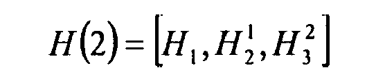


- Two of these possible parity check matrices are looked at in closer detail below.
- Now, a GRS-based regular LDPC code (LDPC 0) may be constructed according to the constraints and design of the (EQ 9) as shown above. The same values of p = 3 , m = 4, ρ = 24 and γ = 8 may be employed as was given above with respect to the Example 1. This GRS-based regular LDPC code (LDPC 0 ) code has rate 0.67.
- Then, a parity check matrix that corresponds to a GRS-based irregular LDPC code (LDPC 1) may be constructed using the modified partial-matrices depicted as follows:

- This GRS-based irregular LDPC code (LDPC 1) has code rate 0.667.
- Then, a parity check matrix that corresponds to another GRS-based irregular LDPC code (LDPC 2) may be constructed using the modified partial-matrices depicted as follows:

- This GRS-based irregular LDPC code (LDPC 2) also has code rate 0.667.
- The following diagram shows an embodiment of how one GRS-based irregular LDPC code may be selected during a design approach from among a plurality of GRS-based irregular LDPC codes.
- FIG. 5 illustrates an embodiment of a
method 500 for selecting a GRS-based irregular LDPC code. This method involves generating a plurality of parity check matrices that corresponds to a plurality of GRS-based irregular LDPC codes (e.g., a plurality of variations of parity check matrices), as shown in ablock 510. The various embodiments described above may be employed to generate the plurality of parity check matrices that corresponds to a plurality of GRS-based irregular LDPC codes. Then, as shown in ablock 520, the method involves determining the performance of each GRS-based irregular LDPC code, having a corresponding parity check matrix, of the plurality of GRS-based irregular LDPC codes (e.g., in terms of BER and/or BLER as a function of SNR). The method then involves selecting a GRS-based irregular LDPC code, having a corresponding parity check matrix, from among the plurality of GRS-based irregular LDPC codes having a best performance, as shown in ablock 530. In some instances, this best performance may be viewed in terms of which GRS-based irregular LDPC code has the lowest error floor in terms of BER/BLER as a function of SNR. The selection of which of the GRS-based irregular LDPC codes should be selected may include additionally or alternatively considering the ease/difficulty of decoder implementation given the particular application, as shown in ablock 532. - FIG. 6 illustrates an
embodiment 600 of generation of a parity check matrix that corresponds to a GRS-based irregular LDPC code using a parity check matrix that corresponds to a GRS-based regular LDPC code. This diagram may assist the reader in understanding the manner by which the parity check matrix is constructed. - As can be seen, a parity check matrix, H reg , that corresponds to a GRS-based regular LDPC code, as indicated by
reference numeral 610, is decomposed into a plurality of partial-matrices (shown as partial matrix, H 1 621, partial matrix,H 2 622, partial matrix,H 3 623, and ... partial matrix, H n 629). The number of partial-matrices into which the parity check matrix, H reg , that corresponds to a GRS-based regular LDPC code is decomposed may be selected by the designer of the GRS-based irregular LDPC code. - Then, at least one of these partial-matrices (e.g., partial matrix, H 3 623) is modified by replacing at least one of the permutation matrices therein with a zero matrix (i.e., a matrix having all 0 valued entries); this modified partial-matrix is referred to as partial-matrix, (H 3 )' 633. Also, any one of the partial-matrices may be modified; the partial-matrix,
H 3 623 being modified into the partial-matrix, (H 3 )' 633 is shown in this diagram just as one possible design choice. Clearly, other of the partial-matrices may alternatively be modified. In addition, more than one of the partial-matrices may be modified without departing from the scope and spirit of the invention. - Thereafter, these partial-matrices are then employed to generate a parity check matrix, H irr , that corresponds to a GRS-based irregular LDPC code, as indicated by
reference numeral 640. - The minimum distance, d min , of such a GRS-based irregular LDPC code is provided as follows:

- It is also noted, as indicated by reference numeral 699, that the minimum distance, d min, of such the GRS-based irregular LDPC code is the same minimum distance, d min, of the GRS-based regular LDPC code that is used to generate the GRS-based irregular LDPC code. In other words, both of the GRS-based irregular LDPC code and the GRS-based regular LDPC code has the same minimum distance, d min. Also, as indicated by the reference numeral 699, each of the GRS-based irregular LDPC code and the GRS-based regular LDPC code has no loops less than size of 6. There are no
size 4 loops in either of the LDPC bipartite graphs that correspond to either of the GRS-based irregular LDPC code and the GRS-based regular LDPC code. - Also, the corresponding LDPC bipartite graph for such a GRS-based irregular LDPC code will have no cycle (or loop) that is less than or equal to 4. The minimum cycle (or loop) of the corresponding LDPC bipartite graph would then be 6. That is to say, each loop of an LDPC bipartite graph that corresponds to the GRS-based irregular LDPC code is at least a size of 6; the code should have no
size 4 loops. - Moreover, given the fact that the GRS-based irregular LDPC code is in fact an "irregular" LDPC code, it will provide for better performance than that of a "regular" LDPC code.
- In this disclosure, various performance diagrams are described in the context of BLER (Block Error Rate) versus Eb/No (ratio of energy per bit Eb to the Spectral Noise Density No). BLER is oftentimes used in the context of wireless communications where if any one bit in a block is determined to be in error, then the entire block is determined to be in error. In some other communication system application, performance may be viewed in terms of BER (Bit Error Rate) vs. Eb/No. This term Eb/No is the measure of SNR (Signal to Noise Ratio) for a digital communication system. When looking at these performance curves, the BLER may be determined for any given Eb/No (or SNR) thereby providing a relatively concise representation of the performance of the decoding approach.
- Several different performance comparisons are provided below that show the improved performance provided by a GRS-based irregular LDPC code when compared to some other codes.
- FIG. 7 illustrates an embodiment of a
performance comparison 700 between a GRS-based regular LDPC code (LDPC0) (shown by reference numeral 710) and a second GRS-based irregular LDPC code (LDPC2) (shown by reference numeral 720) on an AWGN (Additive White Gaussian Noise) communication channel. - This first example considers BPSK (Binary Phase Shift Key) modulation and an AWGN (Additive White Gaussian Noise) communication channel. These performance curves shows that at BLER = 1.5 × 10⁻⁵, LDPC 2 over-performing LDPC 0 by 1.2 dB.
- FIG. 8 illustrates an embodiment of a
performance comparison 800 between a GRS-based irregular LDPC code (LDPC2) (shown by reference numeral 820) and an alternative LDPC code, LDPC(a) (shown using reference numeral 810), on an AWGN communication channel. - The LDPC code, LDPC2, depicted in each of FIG. 7 and FIG. 8 has the corresponding parity check matrix of EQ (12) as provided above. Again, this GRS-based irregular LDPC code (LDPC 2) has code rate 0.667.
- This diagram compares codes LDPC 2 to a
rate 2/3 code that is depicted by LDPC(a). Thisrate 2/3 code (LDPC(a)) is provided by the reference [4] cited below. - [4] LDPC code motion for Mon 28 Feb 2005 Telecon, WWiSE consortium.
- The WWiSE is the WWiSE (World Wide Spectrum Efficiency) is an alliance of companies and entities developing a proposal for the IEEE 802.11n Wireless LAN Standard. More information related to the WWiSE may be found publicly at the following Internet address:
"http://www.wwise.org/" - The following performance curves shows that at BLER = 1.5 × 10⁻⁵, LDPC 2 over-performing the alternative LDPC code, LDPC(a), by 0.55 dB.
- In the IEEE 802.11n application, the Rayleigh fading communication channel is considered and the modulation is 64 QAM (Quadrature Amplitude Modulation) with the mapping given in IEEE 802.11a standard as referenced below in [5]:
- [5] Part 11: Wireless LAN Medium Access Control (MAC) and Physical Layer (PHY) specifications: High-speed Physical Layer in the 5 GHZ Band, IEEE Std 802.11a-1999.
- The entirety of this document is publicly available and may be downloaded from the following Internet site at the time of this filing:
"http://standards.ieee.org/getieee802/download/802.11a-1999.pdf'' - FIG. 9, FIG. 10, FIG. 11, FIG. 12, and FIG. 13 illustrate embodiments of bit to symbol interleaving. Specifically, FIG. 9 shows embodiment 900 (
interleave 2, shown as (II 2)); FIG. 10 shows embodiment 1000 (interleave 3, shown as (II 3)); FIG. 11 shows embodiment 1100 (interleave 4, shown as (II 4)); FIG. 12 shows embodiment 1200 (interleave 5, shown as (Π 4)); and FIG. 13 shows embodiment 1300 (interleave 6, shown as (Π 6); respectively, of various embodiments of bit to symbol interleaving. Each of these is shown as being a 6-bit symbol interleave that operates on an LDPC block of encoded bits (e.g., an LDPC codeword). Clearly, any other number (i.e., n) of columns may be employed to perform a bit to n-bit interleave as well without departing from the scope and spirit of the invention. - Referring to the embodiment 900 (
interleave 2, shown as (Π 2)) of the FIG. 9, anLDPC block 909 is received and may be viewed as being partitioned or divided into a plurality of parts. For example, theLDPC block 909 is divided intopart 0 910,part 1 911,part 2 912,part 3 913,part 4 914, andpart 5 915. Each of these parts is provided to a corresponding column. - Each of the parts is provided to a plurality of column as indicated in the diagram. The 6 bit labels to be symbol mapped (as indicated by reference numeral 919) that are pulled out from the columns are as follows (MSB (Most Significant Bit) on left ... LSB (Least Significant Bit) on right):
1st 6 bit label: C0CkC2kC3kC4kC5k
2nd 6 bit label: C1Ck+1C2k+1C3k+1C4+1C5k+1
...
nth 6 bit label: Ck-1C2k-1C3k-1C4k-1C5k-1C6k-1 - Each of the parts that is provided to each of the corresponding columns has k bits. The total number of bits of the
LDPC block 909 is 6k. - As can be seen with respect to the LSB and MSB of the bits that are pulled out from the rows, there is no column permutation with respect to the columns into which the parts are partitioned as indicated by the
reference numeral 929. The bits (c5k-1, ..., c4k+1, C4k) and the LSB bits (c6k-1, ..., c5k+1, C5k) are redundancy bits as selected from the LDPC block 909 as indicated by thereference numerals - Referring to the embodiment 1000 (interleave 3, shown as (Π 3)) of the FIG. 10, an
LDPC block 1009 is received and may be viewed as being partitioned or divided into a plurality of parts. For example, theLDPC block 1009 is divided intopart 0 1010,part 1 1011,part 2 1012,part 3 1013,part 4 1014, andpart 5 1015. Each of these parts is provided to a corresponding column. - Each of the parts is provided to a plurality of columns in an analogous fashion as the previous embodiment. However, the columns are permuted as indicated in the diagram.
- The 6 bit labels to be symbol mapped (as indicated by reference numeral 1019) that are pulled out from the columns are as follows (MSB on left ... LSB on right):
1st 6 bit label: C4kC2k C0C5kC3kCk
2nd 6 bit label: C4k+1C2k+1C1C5k+1C3k+1Ck+1
nth 6 bit label: C5k-1C3k-1Ck-1C6k-1C4k-1C2k-1 - Each of the parts that is provided to each of the corresponding columns has k bits. The total number of bits of the
LDPC block 1009 is 6k. - As can be seen with respect to the LSB (Least Significant Bit) and MSB of the bits that are pulled out from the rows, there is a column permutation with respect to the columns into which the parts are partitioned as indicated by the
reference numeral 1029. The MSB bits (c5k-1, ..., c4k+1, c4k) and the bits (c6k-1, ..., c5k+1, c5k) are redundancy bits as selected from theLDPC block 1009 as indicated by thereference numerals - Referring to the embodiment 1100 (interleave 4, shown as (Π 4)) of the FIG. 11, an
LDPC block 1109 is received and may be viewed as being partitioned or divided into a plurality of parts. For example, theLDPC block 1109 is divided intopart 0 1110,part 1 1111,part 2 1112,part 3 1113,part 4 1114, andpart 5 1115. Each of these parts is provided to a corresponding column. - Each of the parts is provided to a plurality of columns in an analogous fashion as the previous embodiment. However, the columns are permuted as indicated in the diagram.
- The 6 bit labels to be symbol mapped (as indicated by reference numeral 1119) that are pulled out from the columns are as follows (MSB on left ... LSB on right):
1st 6 bit label: C3kC0C4kC2kCkC5k
2nd 6 bit label: C3k+1C1C4k+1C2k+1Ck+1C5k+1
nth 6 bit label: C4k-1Ck-1C5k-1C3k-1C2k-1C6k-1 - Each of the parts that is provided to each of the corresponding columns has k bits. The total number of bits of the
LDPC block 1109 is 6k. - As can be seen with respect to the LSB (Least Significant Bit) and MSB of the bits that are pulled out from the rows, there is a column permutation with respect to the columns into which the parts are partitioned as indicated by the
reference numeral 1129. The bits (c5k-1, ..., c4k+1, c4k) and the LSB bits (c6k-1, ..., c5k+1, c5k) are redundancy bits as selected from theLDPC block 1109 as indicated by thereference numerals - Referring to the embodiment 1200 (interleave 5, shown as (II 5)) of the FIG. 12, an
LDPC block 1209 is received and may be viewed as being partitioned or divided into a plurality of parts. For example, theLDPC block 1209 is divided intopart 0 1210,part 1 1211,part 2 1212,part 3 1213,part 4 1214, andpart 5 1215. Each of these parts is provided to a corresponding column. - Each of the parts is provided to a plurality of columns in an analogous fashion as the previous embodiment. However, the columns are permuted as indicated in the diagram.
- The 6 bit labels to be symbol mapped (as indicated by reference numeral 1219) that are pulled out from the columns are as follows (MSB on left ... LSB on right):
1st 6 bit label: c2kc0c4kckc3kc5k
2nd 6 bit label: c2k+1c1c4k+1ck+1c3k+1c5k+1
nth 6 bit label: c3k-1ck-1c5k-1c2k-1c4k-1c6k-1 - Each of the parts that is provided to each of the corresponding columns has k bits. The total number of bits of the
LDPC block 1209 is 6k. - As can be seen with respect to the LSB (Least Significant Bit) and MSB of the bits that are pulled out from the rows, there is a column permutation with respect to the columns into which the parts are partitioned as indicated by the
reference numeral 1229. The bits (c5k-1, ..., c4k+1, c4k) and the LSB bits (c6k-1, ..., c5k+1, c5k) are redundancy bits as selected from theLDPC block 1209 as indicated by thereference numerals - Referring to the embodiment 1300 (interleave 6, shown as (Π 6)) of the FIG. 13, an
LDPC block 1309 is received and may be viewed as being partitioned or divided into a plurality of parts. For example, theLDPC block 1309 is divided intopart 0 1310,part 1 1311,part 2 1312,part 3 1313,part 4 1314, andpart 5 1315. Each of these parts is provided to a corresponding column. - Each of the parts is provided to a plurality of columns in an analogous fashion as the previous embodiment. However, the columns are permuted as indicated in the diagram.
- The 6 bit labels to be symbol mapped (as indicated by reference numeral 1319) that are pulled out from the columns are as follows (MSB on left ... LSB on right):
1st 6 bit label: c0c2kc4kckc3kc5k
2nd 6 bit label: c1c2k+1c4k+1ck+1c3k+1c5k+1
nth 6 bit label: ck-1c3k-1c5k-1c2k-1c4k-1c6k-1 - Each of the parts that is provided to each of the corresponding columns has k bits. The total number of bits of the
LDPC block 1309 is 6k. - As can be seen with respect to the LSB (Least Significant Bit) and MSB of the bits that are pulled out from the rows, there is a column permutation with respect to the columns into which the parts are partitioned as indicated by the
reference numeral 1329. The bits (c5k-1, ..., c4k+1, c4k) and the LSB bits (c6k-1, ..., c5k+1, c5k) are redundancy bits as selected from theLDPC block 1309 as indicated by thereference numerals - FIG. 14 illustrates an embodiment of a
performance comparison 1400 between a GRS-based regular LDPC code (LDPC0) (shown by reference numeral 1405), a first GRS-based irregular LDPC code (LDPC1) (shown by reference numeral 1410), and a second GRS-based irregular LDPC code (LDPC2) (shown by reference numeral 1420) on a Rayleigh fading communication channel. This embodiment shows that both irregular LDPC 1 and LDPC 2 out performing LDPC 0 by at least 3 dB with BLER (block error rate). - The GRS-based regular LDPC code (LDPC 0) is constructed according to the constraints and design of the (EQ 9) as shown above. The same values of p = 3 , m = 4 , ρ = 24 and γ = 8 can be employed as was given above with respect to the Example 1. This GRS-based regular LDPC code (LDPC 0) code has rate 0.67.
- The parity check matrix that corresponds to the GRS-based irregular LDPC code (LDPC 1) is constructed using the modified partial-matrices as also provided above with respect to EQ (11) (which is provided again here for ease of the reader):

- This GRS-based irregular LDPC code (LDPC 1) has code rate 0.667.
- The parity check matrix that corresponds to the GRS-based irregular LDPC code (LDPC 2) is constructed using the modified partial-matrices as also provided above with respect to EQ (12) (which is provided again here for ease of the reader):

- This GRS-based irregular LDPC code (LDPC 2) also has code rate 0.667.
- FIG. 15 illustrates an embodiment of a
performance comparison 1500 between a first GRS-based irregular LDPC code (LDPC1) (shown using reference numeral 1510), a second GRS-based irregular LDPC code (LDPC2) (shown using reference numeral 1520), and an alternative LDPC code, LDPC(b) (shown using reference numeral 1505), on a communication channel. - This embodiment compares the codes LDPC, 1510 and LDPC 2 1520 to the
rate 2/3 code, LDPC(b) 1505. That code, LDPC(b) 1505, has the same code length as 1944 and is also irregular. With the bit to symbol interleave that is provided in Fig. 9, the corresponding performances are given in Fig. 15. The GRS-based irregular codes constructed herein give 1 dB performance improvement. - FIG. 16 and FIG. 17 illustrate alternative embodiments of bit to symbol interleaving. Specifically, FIG. 16 and FIG. 17 illustrate embodiment 1600 (interleave 0, shown as (Π 0)), and embodiment 1700 (interleave 1, shown as (Π 1)), respectively, of bit to symbol interleaving. As with previous embodiments, each of these is shown as being a 6-bit symbol interleave that operates on an LDPC block of encoded bits (e.g., an LDPC codeword). Clearly, any other number (i.e., n) of columns may be employed to perform a bit to n-bit interleave as well without departing from the scope and spirit of the invention. In the
embodiment 1600, anLDPC block 1609 is provided directly to each of a plurality of columns. Rather than put each of a plurality of parts of theLDPC block 1609 into corresponding columns (as done in some of the previous embodiments), a first bit of theLDPC block 1609 is provided to a first column, a second bit of the LDPC block is provided to a second column, a third bit of the LDPC block is provided to a third column, and so on. As can be seen, the order of the columns is not permuted (0 1 2 3 4 5) , as indicated by thereference numeral 1629. Depending on the symbol size employed (e.g., n bit symbol size), then the n+1 symbol is provided to the first column in a wrapping around procedure as depicted in the diagram. - The 6 bit labels to be symbol mapped (as indicated by reference numeral 1619) that are pulled out from the columns are as follows (MSB on left ... LSB on right):
1st 6 bit label: c0c1c2c3c4c5
2nd 6 bit label: c6c7c8c9c10c11
...
nth 6 bit label: C6k-6C6k-5C6k-4C6k-3C6k-2C6k-1 - The total number of bits of the
LDPC block 1609 is 6k. As can be seen with respect to the LSB and MSB of the bits that are of the mapped pulled out from the rows, there is no column permutation with respect to the columns into which the parts are partitioned as indicated by thereference numeral 1629. - In the embodiment 1700, an
LDPC block 1709 is provided directly to each of a plurality of columns. Rather than put each of a plurality of parts of theLDPC block 1609 into corresponding columns (as done in some of the previous embodiments), a first bit of theLDPC block 1609 is provided to a first column, a second bit of the LDPC block is provided to a second column, a third bit of the LDPC block is provided to a third column, and so on. As can be seen, the order of the columns is in fact permuted (0 2 4 1 3 5), as indicated by thereference numeral 1729. Depending on the symbol size employed (e.g., n bit symbol size), then the n+1 symbol is provided to the first column in a wrapping around procedure as depicted in the diagram. - The 6 bit labels to be symbol mapped (as indicated by reference numeral 1719) that are pulled out from the columns are as follows (MSB on left ... LSB on right):
1st 6 bit label: c0c2c4c1c3c5
2nd 6 bit label: c5c7c9c6c8c10
nth 6 bit label: C6k-6C6k-4C6k-2C6k-5C6k-3C6k-1 - The total number of bits of the
LDPC block 1709 is 6k. As can be seen with respect to the LSB and MSB of the bits that are of the mapped pulled out from the rows, there is in fact a column permutation with respect to the columns into which the parts are partitioned as indicated by thereference numeral 1729. - In each of the
embodiments 1600 of FIG. 16 and embodiment 1700 of FIG. 17, the entire LDPC block need not be available before performing the symbol formation and symbol mapping. When comparing this to each of theembodiments 900 of FIG. 9,embodiment 1000 of FIG. 10, embodiment 1100 of FIG. 11,embodiment 1200 of FIG. 12, andembodiment 1300 of FIG. 13. Those embodiments (900, 1000, 1100, 1200, and 1300) require a bit of memory management and incur some latency when compared to theembodiments 1600 and 1700. However, there can be a significant improvement in performance when doing those embodiments (900, 1000, 1100, 1200, and 1300) of bit to symbol interleave when compared to theembodiments 1600 and 1700. Therefore, a small price to pay in terms of latency may yield a large payoff in terms of performance. - Clearly, for each of the embodiments depicted in FIG. 16 and FIG. 17, other sized LDPC blocks (e.g., having different total numbers of bits) and symbols having other numbers of bits (e.g., labels for symbols having n bits and n corresponding columns) may also be employed herein without departing from the scope and spirit of the invention. A designer is provided wide latitude is selecting the LDPC block size and type as well as the manner of bit to symbol interleaving without departing from the scope and spirit of the invention.
- With other interleaves such as those provided in FIG. 16 and FIG. 17,
codes LDPC 1 1210 and LDPC 2 1220 out perform LDPC(b) 1205 by approximately 0.5 to 0.8 dB. - The following four diagrams show the performance of 4 different GRS-based irregular LDPC codes to each of 4 alternative LDPC codes, namely, LDPC(c) (1944, 972), LDPC(d) (1944, 1296), LDPC(e) (1944, 487), and LDPC(f) (1944, 1620). Each of these 4 different GRS-based irregular LDPC codes, designed according to the novel approach presented herein, has a corresponding low parity check matrix; these low density parity check matrices are provided in the APPENDIX.
- Later in the APPENDIX, 3 additional low density parity check matrices corresponding to 3 different GRS-based irregular LDPC codes are also provided.
- FIG. 18 illustrates an embodiment of a
performance comparison 1800 between a GRS-based irregular LDPC (1944, 973) code (1) (shown by reference numeral 1820) and a first code, LDPC(c) (1944, 972) (shown by reference numeral 1810), on a communication channel. - This shows the performance of these two
code rate 1/2 codes on an AWGN communication channel in terms of BLER vs. SNR (or Eb/No). As can be seen, at a BLER of 1.5 x 10⁻⁵ , the GRS-based irregular LDPC (1944, 973) code (1) 1820 outperforms the LDPC(c) (1944, 972) code 1810 by approximately 0.33 dB. - FIG. 19 illustrates an embodiment of a
performance comparison 1900 between a GRS-based irregular LDPC (1944, 1297) code (2) (shown by reference numeral 1920) and a second code, LDPC(d) (1944, 1296) (shown by reference numeral 1910), on a communication channel. - FIG. 20 illustrates an embodiment of a
performance comparison 2000 between a GRS-based irregular LDPC (1944, 487) code (3) (shown by reference numeral 2020) and a third code, LDPC(e) (1944, 486) (shown by reference numeral 2010), on a communication channel. - FIG. 21 illustrates an embodiment of a
performance comparison 2100 between a GRS-based irregular LDPC (1944, 1621) code (4) (shown by reference numeral 2120) and a fourth code, LDPC(t) (1944, 1620) (shown by reference numeral 2110), on a communication channel. - FIG. 22A illustrates an embodiment of a
method 2200 for generating an LDPC coded signal. Thismethod 2200 involves constructing a generator matrix that corresponds to a parity check matrix of a corresponding GRS-based irregular LDPC code, as shown in ablock 2210. When provided any parity check matrix that corresponds to an LDPC code, a corresponding generator matrix may be constructed. Themethod 2200 then involves encoding at least one information bit using the generator matrix thereby generating at least one LDPC codeword of an LDPC coded signal, as shown in a block 2220. This encoding operation may be viewed as taking place in an encoder at a transmitter end of a communication channel. By encoding the at least one information bit using this constructed generator matrix (that corresponds to the parity check matrix), the decoding of the LDPC coded signal may then be performed using the parity check matrix that is used to construct the generator matrix. Any of a number of hardware devices (e.g., transmitters, transceivers, encoders, etc.) that include this encoding functionality may be implemented to perform these operations in any of a wide variety of communication system types. - FIG. 22B illustrates an embodiment of a
method 2205 for decoding an LDPC coded signal. Thismethod 2205 may be viewed as receiving an LDPC coded signal, as shown in ablock 2215. Then, themethod 2205 may be viewed as decoding an LDPC coded signal, that has been encoded using a GRS-based irregular LDPC code, using a parity check matrix that corresponds to the GRS-based irregular LDPC code thereby making a best estimate of at least one information bit encoded within the LDPC coded signal, as shown in a block 2225. From some perspectives, this decoding operation may be viewed as being performed in a decoder located at a receiver end of a communication channel. Any of a number of hardware devices (e.g., receivers, transceivers, decoders, etc.) that include this decoding functionality may be implemented to perform these operations in any of a wide variety of communication system types. - Moreover, it is noted that the formation of a parity check matrix that corresponds to a GRS-based irregular LDPC code may take following form, where P is an n x n (e.g., 81 × 81 in one embodiment) permutation matrix.
- Some examples of a P matrix may be provided as follows (as shown within some 3 × 3 embodiments):

- A zero matrix, x, may be represented as follows (as shown within various embodiments):


- In one embodiment, each of the permutation matrices, P, and the zero matrices, x, are 81 X 81 matrices when implemented within an LDPC code having a block length of 1944.
- One 1st possible code structure is based on a parity check matrix, H, that corresponds to a GRS-based irregular LDPC code, for a code rate of 973/1944(>1/2), which may be approximated as being a code rate of 0.5. The form of the parity check matrix, H, is provided as follows: H =[Ha,Hb]. Because of the size of this parity check matrix, H, it is depicted using 2 paragraphs. The first paragraph depicts columns 1-12 and rows 1-12, and the second paragraph depicts columns 13-24 and rows 1-12.


- A 2nd possible code structure is based on a parity check matrix, H, that corresponds to a GRS-based irregular LDPC code, for a code rate of 2/3, which may be approximated as being a code rate of 0.667. The form of this parity check matrix, H, is provided as follows: H = [H a , H b ]. Because of the size of this parity check matrix, H, it is depicted using 2 paragraphs. The first paragraph depicts columns 1-12 and rows 1-8, and the second paragraph depicts columns 13-24 and rows 1-8.


- A 3rd possible code structure is based on a parity check matrix, H, that corresponds to a GRS-based irregular LDPC code, for a code rate of 3/4. The form of the parity check matrix, H, is provided as follows: H = [H a , H b ]. Because of the size of this parity check matrix, H, it is depicted using 2 paragraphs. The first paragraph depicts columns 1-12 and rows 1-6, and the second paragraph depicts columns 13-24 and rows 1-6.


- A 4th possible code structure is based on a parity check matrix, H, that corresponds to a GRS-based irregular LDPC code, for a code rate of 5/6, which may be approximated as being a code rate of 0.833. The form of the parity check matrix, H, is provided as follows: H = [H a ,H b ]' Because of the size of this parity check matrix, H, it is depicted using 2 paragraphs. The first paragraph depicts columns 1-12 and rows 1-4, and the second paragraph depicts columns 13-24 and rows 1-4.


- For each of these 3 embodiments, the values and forms of H and P are provided above with respect to the 81 x 81 embodiment for each of the permutation matrices, P, and each of the zero matrices, x.
- The GRS-based irregular LDPC coded constructed according to each of these possible parity check matrices achieve better BLER performance at all rates and SNRs. In addition, these codes have lower error floors. Each of these GRS-based irregular LDPC codes is simulated down to a BLER of 1.5 x 10⁻⁵, which is appropriate for aggregated frames of 8192 bytes.
- The performance of the 1 sl possible code structure is described above with respect to FIG. 18.
- FIG. 23 illustrates an embodiment of a
performance comparison 2300 between a GRS-based irregular LDPC (1944, 1296) code (5) (shown using reference numeral 2320) and the second code, LDPC(d) (1944, 1296) (shown using reference numeral 2310), on a communication channel. - This shows the performance of these two
code rate 2/3 codes on an AWGN communication channel in terms of BLER vs. SNR (or Eb/No). As can be seen, at a BLER of 1.5×10⁻⁵, the GRS-based irregular LDPC (1944, 1296) code (5) 2320 outperforms the LDPC(d) (1944, 1296) code 2310 by approximately 0.6 dB. - FIG. 24 illustrates an embodiment of a
performance comparison 2400 between a GRS-based irregular LDPC (1944, 486) code (6) (shown using reference numeral 2420) and the third code, LDPC(e) (1944, 486) (shown using reference numeral 2410), on a communication channel. - This shows the performance of these two
code rate 3/4 codes on an AWGN communication channel in terms of BLER vs. SNR (or Eb/No). As can be seen, at a BLER of 1.5×10⁻⁵, the GRS-based irregular LDPC (1944, 486) code (6) 2420 outperforms the LDPC(e) (1944, 486) code 2410 by approximately 0.22 dB. - FIG. 25 illustrates an embodiment of a
performance comparison 2500 between a GRS-based irregular LDPC (1944, 1620) code (7) (shown using reference numeral 2520) and the fourth code, LDPC(f) (1944, 1620) (shown using reference numeral 2510), on a communication channel. - This shows the performance of these two
code rate 5/6 codes on an AWGN communication channel in terms of BLER vs. SNR (or Eb/No). As can be seen, at a BLER of 1.5×10⁻⁵, the GRS-based irregular LDPC (1944, 1620) code (7) 2520 outperforms the LDPC(f) (1944, 1620) code 2510 code by approximately 0.11 dB. - The complexity of each of these possible code structures may be summarized as a function of the total number of edges within a corresponding LDPC bipartite graph; this is directly related to the mount of memory required for the messages. A worst case is 648 more that that which is shown.
Table 2 Code rate = 1/2 LDPC(c) (1944, 972), 6966 edges GRS-based irregular LDPC (1944, 973) code (1), 7776 edges Code rate = 2/3 LDPC(d) (1944, 1296), 7128 edges GRS-based irregular LDPC (1944, 1296) code (5), 7695 edges Code rate = 3/4 LDPC(e) (1944, 486), 6803 edges GRS-based irregular LDPC (1944, 486) code (6), 7695 edges Code rate = 5/6 LDPC(f) (1944, 1620) code, 6803 edges GRS-based irregular LDPC (1944, 1620) code (7), 7047 edges - Using these various design approaches provided herein, a complete family of LDPC codes having a better performance than known before is made available for designers. Also, the very low error floors provided by these codes are appropriate for the high throughput applications required in many applications. Moreover, the complexity of such a decoder implemented to decode such coded signals is relatively low while providing this improved performance.
- FIG. 26 illustrates an embodiment of a
performance comparison 2600 between a first GRS-based irregular LDPC code (LDPC1), a second GRS-based irregular LDPC code (LDPC2), and an alternative LDPC code, LDPC(b), using different types of bit to symbol interleaving, on a communication channel. This communication channel is a Rayleigh fading communication channel, and the modulation employed is 64 QAM. The LDPC block size of each of these codes (LDPC1 and LDPC2) is 1944, and the number of decoding iterations for each of these performance curves is 12. The alternative LDPC code, LDPC(b), has a code rate of 2/3, a code length of 1944 and is also an irregular LDPC code. - The parity check matrix that corresponds to the GRS-based irregular LDPC code (LDPC 1) is constructed using the modified partial-matrices as also provided above with respect to EQ (11) (which is provided again here for ease of the reader):

- This GRS-based irregular LDPC code (LDPC 1) has code rate 0.667.
- The parity check matrix that corresponds to the GRS-based irregular LDPC code (LDPC 2 ) is constructed using the modified partial-matrices as also provided above with respect to EQ (12) (which is provided again here for ease of the reader):

- This GRS-based irregular LDPC code (LDPC 2) also has code rate 0.667.
- Several different types of bit to symbol interleaving are employed; some of these bit to symbol interleaves are depicted above within the FIG. 9 (Π2), FIG. 10 (Π3), FIG. 11 (Π4), FIG. 12 (Π5), FIG. 13 (Π6), FIG. 16 (Π0), and FIG. 17 (Π1), respectively. Clearly, alternative permuting of the columns employed therein could also be performed without departing from the scope and spirit of the invention.
- Specifically, the performance of GRS-based irregular LDPC code (LDPC 1) is depicted using bit to symbol interleaving (Π1) (shown using reference numeral 2611) and bit to symbol interleaving (Π2) (shown using reference numeral 2612).
- The performance of GRS-based irregular LDPC code (LDPC 2) is depicted using bit to symbol interleaving (Π1) (shown using reference numeral 2621), bit to symbol interleaving (Π2) (shown using reference numeral 2622), bit to symbol interleaving (Π4) (shown using reference numeral 2624), bit to symbol interleaving (Π5) (shown using reference numeral 2625), and bit to symbol interleaving (Π6) (shown using reference numeral 2626).
- The performance of alternative LDPC code, LDPC(b), is depicted using bit to symbol interleaving (Π0) (shown using reference numeral 2630), bit to symbol interleaving (Π1) (shown using reference numeral 2631), bit to symbol interleaving (Π2) (shown using reference numeral 2632), bit to symbol interleaving (Π3) (shown using reference numeral 2633), and bit to symbol interleaving (Π6) (shown using reference numeral 2636).
- As can be seen, at a BLER of 1.5 x 10⁻⁵ , each of the GRS-based irregular LDPC code (LDPC 1 ) and the GRS-based irregular LDPC code (LDPC 2)outperforms the alternative LDPC code, LDPC(b), by approximately 0.8 dB.
- As can be seen when considering these various performance diagrams, the GRS-based irregular LDPC codes that have been constructed according to the approach provided herein out perform other codes in terms of providing for lower error floors in terms of BLER as a function of SNR.
- In addition, it is clear that the appropriate selection of a bit to symbol interleaving can provide for a significant increase in performance for each of the various LDPC codes whose performance is compared here. This principle may be extended to a wide variety of LDPC codes including those not specifically presented herein. There are many approaches by which the bit to symbol interleaving of an LDPC block may be performed.
- One possible approach seeks to correspond those LDPC coded bits of the LDPC block that have higher coding strength (i.e., higher bit degree thereby indicating relatively more edges connected between those bit nodes and corresponding check nodes) to the LSBs of an n-bit label that is to be symbol mapped according to a modulation (having a constellation shape and corresponding mapping). This approach also seeks to correspond those LDPC coded bits of the LDPC block that have lower coding strength (i.e., lower bit degree thereby indicating relatively fewer edges connected between those bit nodes and corresponding check nodes) to the MSBs of an n-bit label that is to be symbol mapped according to a modulation (having a constellation shape and corresponding mapping). This approach seeks to align those LDPC coded bits (of the LDPC block) that have relatively higher coding strength to the relatively weak bit locations within the n-bit label (i.e., LSBs), and to align those LDPC coded bits (of the LDPC block) that have relatively lower coding strength to the relatively strong bit locations within the n-bit label (i.e., MSBs). This approach can be referred to as "strong to weak and weak to strong".
- Another possible approach seeks to correspond those LDPC coded bits of the LDPC block that have higher coding strength (i.e., higher bit degree thereby indicating relatively more edges connected between those bit nodes and corresponding check nodes) to the MSBs of an n-bit label that is to be symbol mapped according to a modulation (having a constellation shape and corresponding mapping). This approach also seeks to correspond those LDPC coded bits of the LDPC block that have lower coding strength (i.e., lower bit degree thereby indicating relatively fewer edges connected between those bit nodes and corresponding check nodes) to the LSBs of an n-bit label that is to be symbol mapped according to a modulation (having a constellation shape and corresponding mapping). This approach seeks to align those LDPC coded bits (of the LDPC block) that have relatively higher coding strength to the relatively strong bit locations within the n-bit label (i.e., MSBs), and to align those LDPC coded bits (of the LDPC block) that have relatively lower coding strength to the relatively weak bit locations within the n-bit label (i.e., LSBs). This approach can be referred to as "strong to strong and weak to weak".
- Also, when considering many of the 6 bit labels and interleaving presented above, the first 3 bits (starting at the MSB) can be considering as an in-phase component, and the last 3 bits (ending at the MSB) can be considering as a quadrature-phase component as in an I, Q (In-phase, Quadrature) implementation. From this perspective, each of these 3 bit groups can also be appropriately interleaved such that these 3 bit groups may also be mapped according to either of the "strong to weak and weak to strong" or the "strong to strong and weak to weak" approaches described above.
- For example, both of the in-phase component (MSB and next 2 bits) and the quadrature-component (2 bits before LSB and LSB) can be mapped according to the "strong to weak and weak to strong" approach. Alternatively, both of the in-phase component (MSB and next 2 bits) and the quadrature-component (2 bits before LSB and LSB) can be mapped according to the "strong to strong and weak to weak" approach.
- In even other approaches, the in-phase component (MSB and next 2 bits) can be can be mapped according to the "strong to weak and weak to strong" approach, and the quadrature-component (2 bits before LSB and LSB) can be mapped according to the "strong to strong and weak to weak" approach. In even another approach, the in-phase component (MSB and next 2 bits) can be can be mapped according to the "strong to strong and weak to weak" approach, and the quadrature-component (2 bits before LSB and LSB) can be mapped according to the "strong to weak and weak to strong" approach.
- However, after considering many of the interleaves presented above that do various combinations of these approaches that are described just above, it is clear that there can be no generalization made as to which of the bit to symbol interleave approaches provides for the bext performance. For example, when considering each of the "strong to weak and weak to strong" or the "strong to strong and weak to weak" approaches described above as well as combinations thereof (e.g., when considering the in-phase component and the quadrature component separately), it is clear that there is no generalized approach which can be stated by which to select the mapping of the strength of the LDPC coded bits to bit locations within the n-bit labels that are to be symbol mapped.
- Rather, the best performance is a function of both the coding selected (e.g., the GRS-based irregular LDPC code selected) as well as the bit to symbol interleave selected. At the time of this filing, there appears no generalization that can be made. Once a parituclar LDPC code is selected, it seems clear that a number of bit to symbol interleaves should be considered in an effort to find the combination that provides the best performance.
- It is also noted that the methods described within the preceding figures may also be performed within any number of appropriate system and/or apparatus designs without departing from the scope and spirit of the invention.
- In view of the above detailed description of the invention and associated drawings, other modifications and variations will now become apparent. It should also be apparent that such other modifications and variations may be effected without departing from the spirit and scope of the invention.


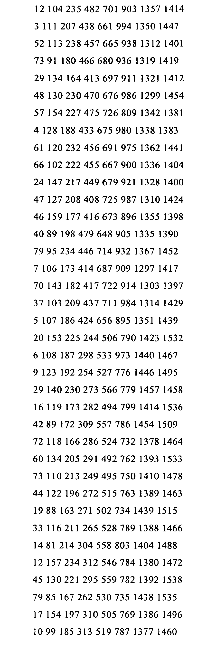


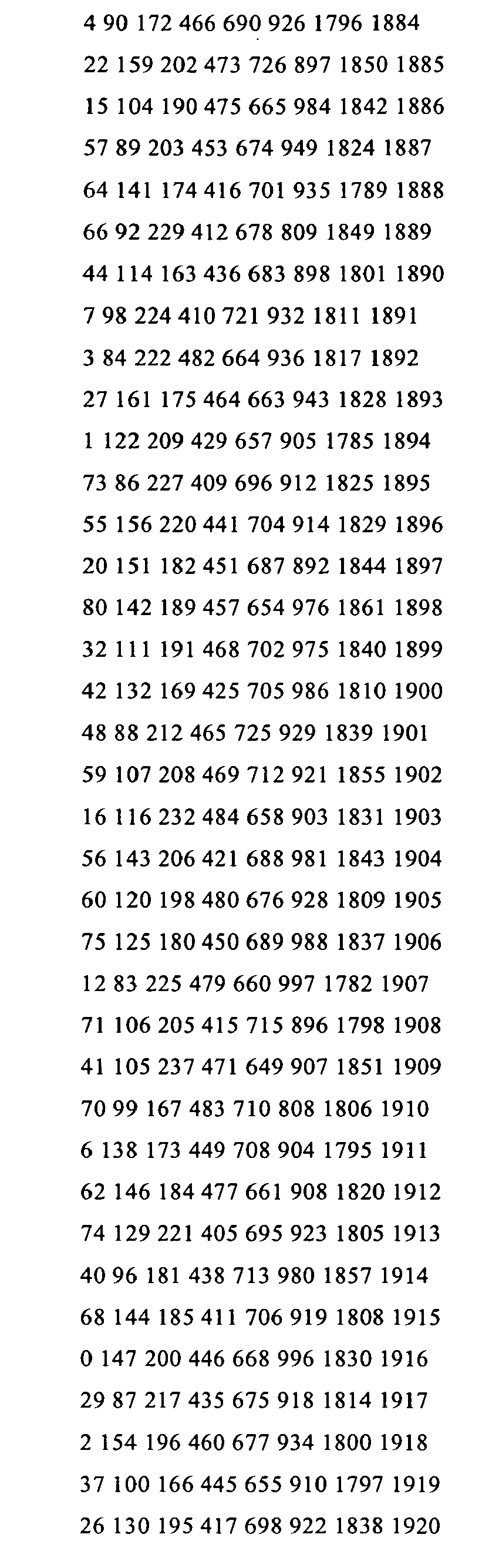


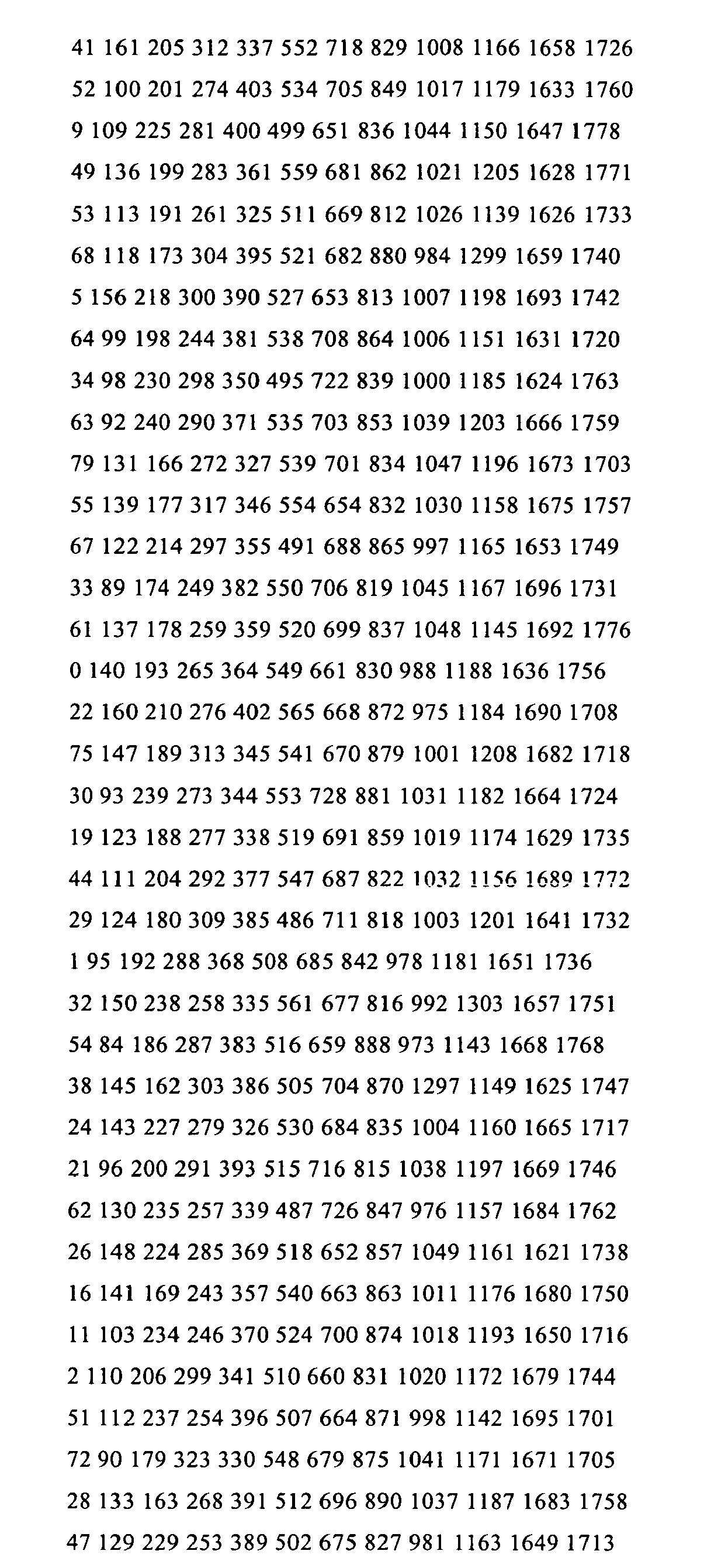


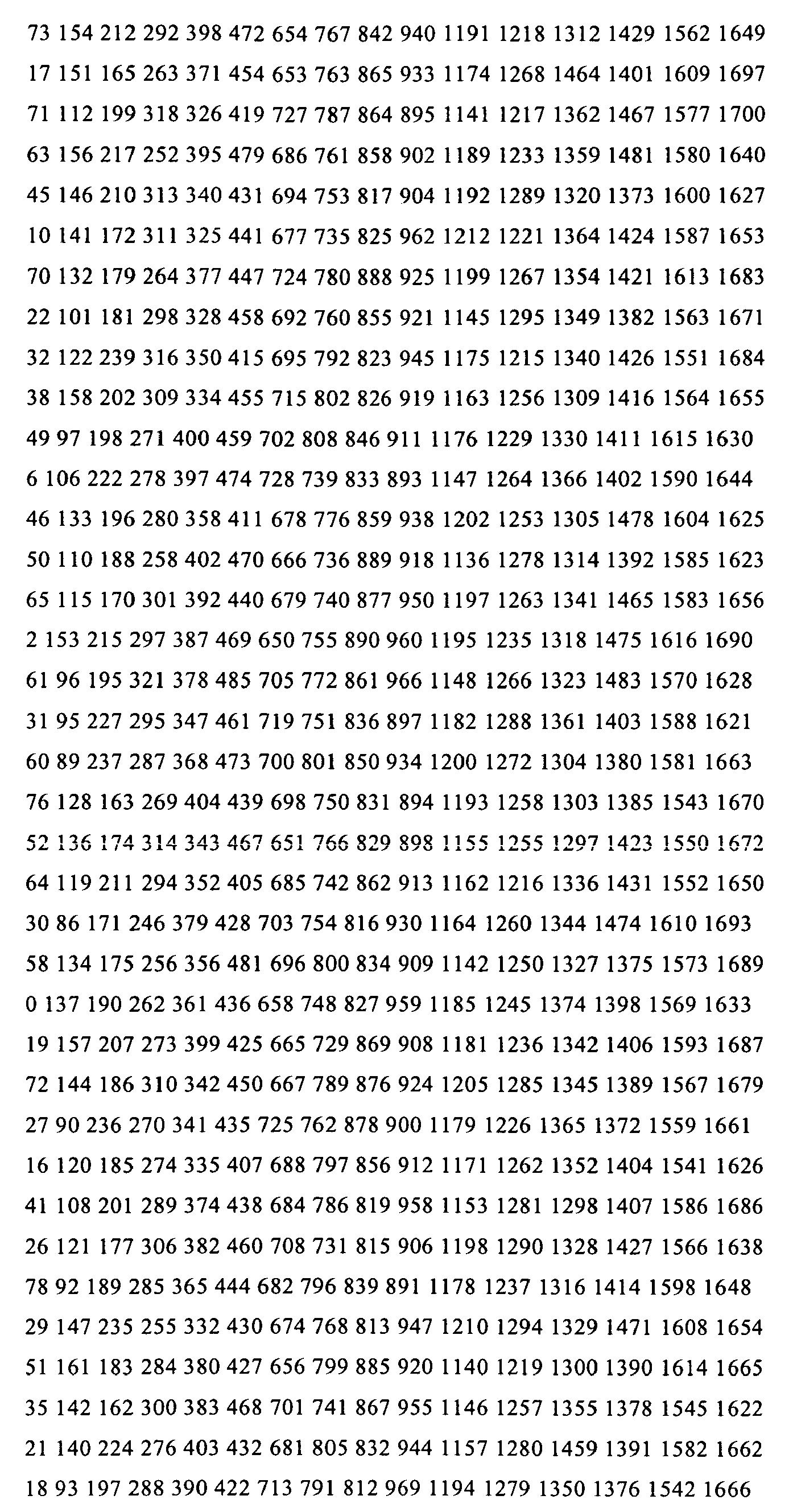


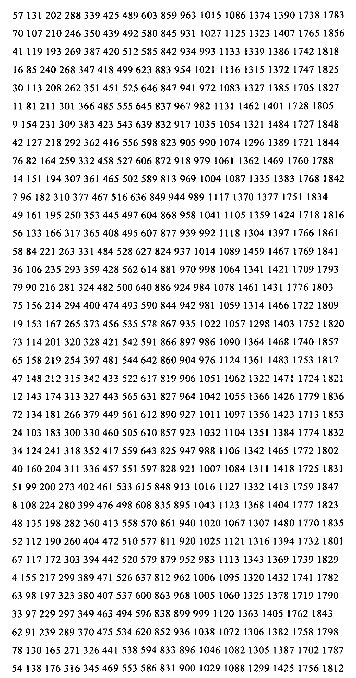


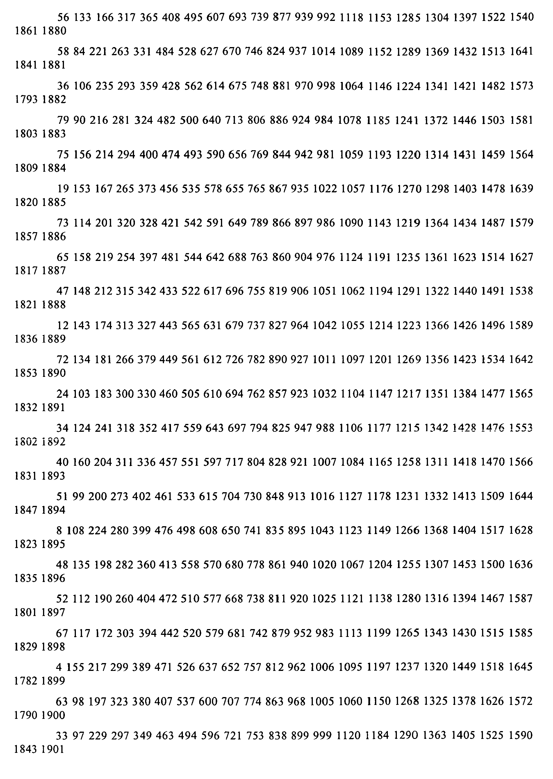
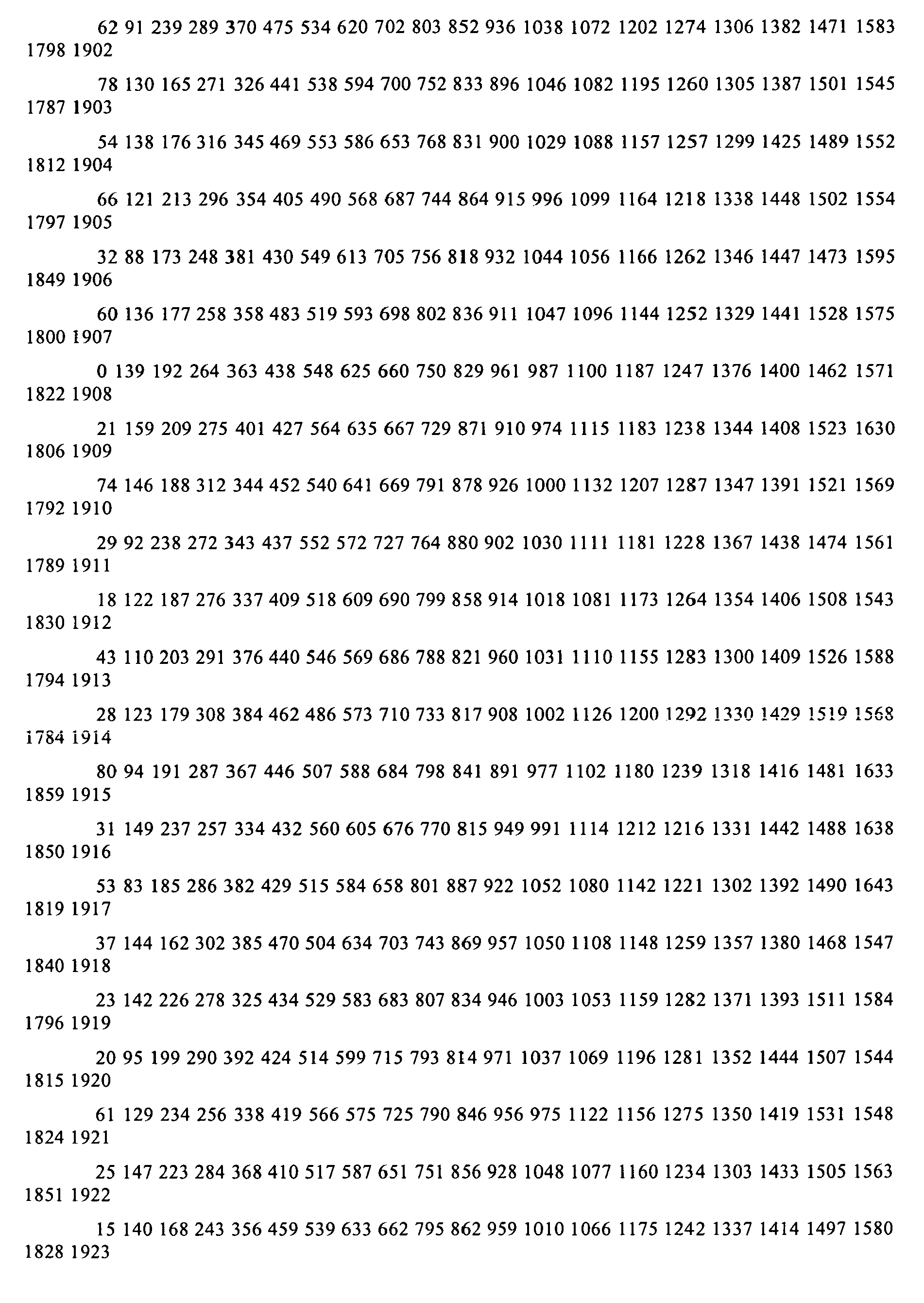


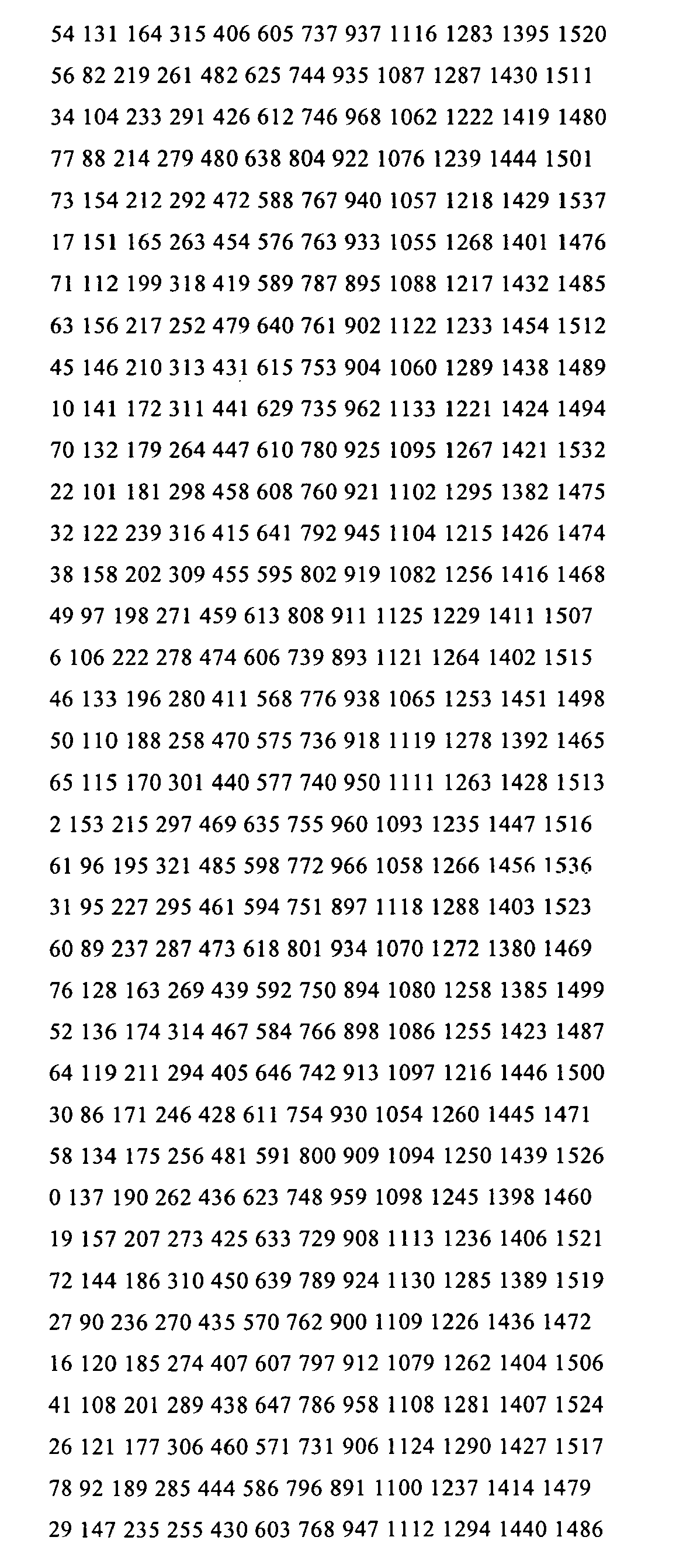


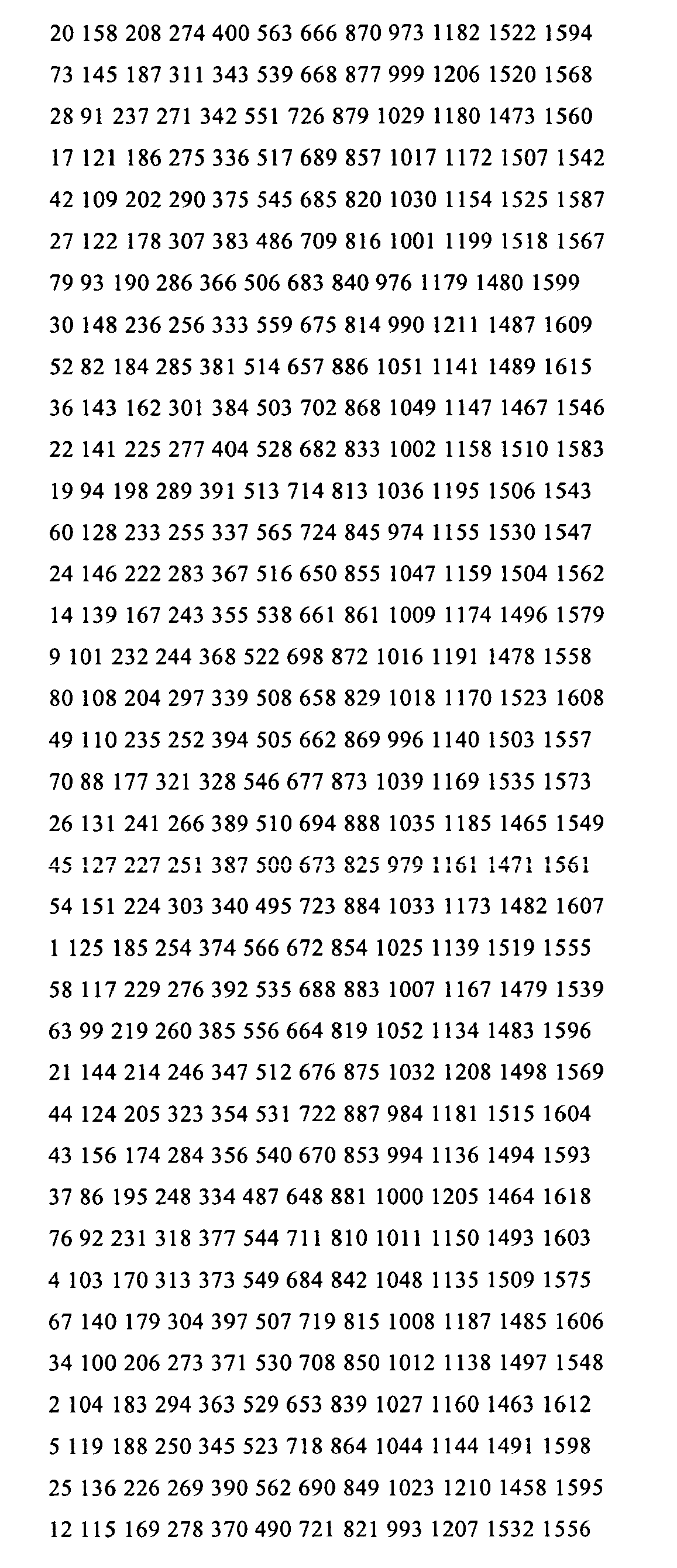


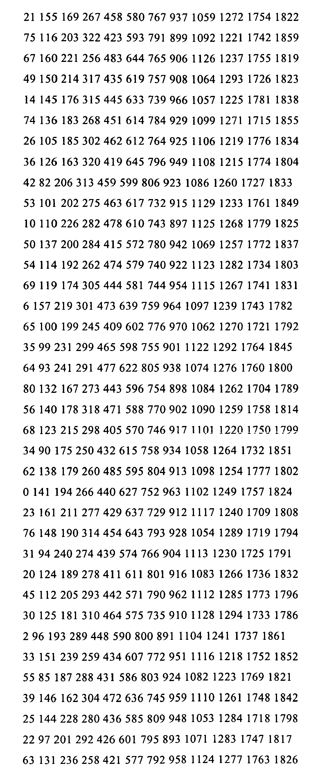


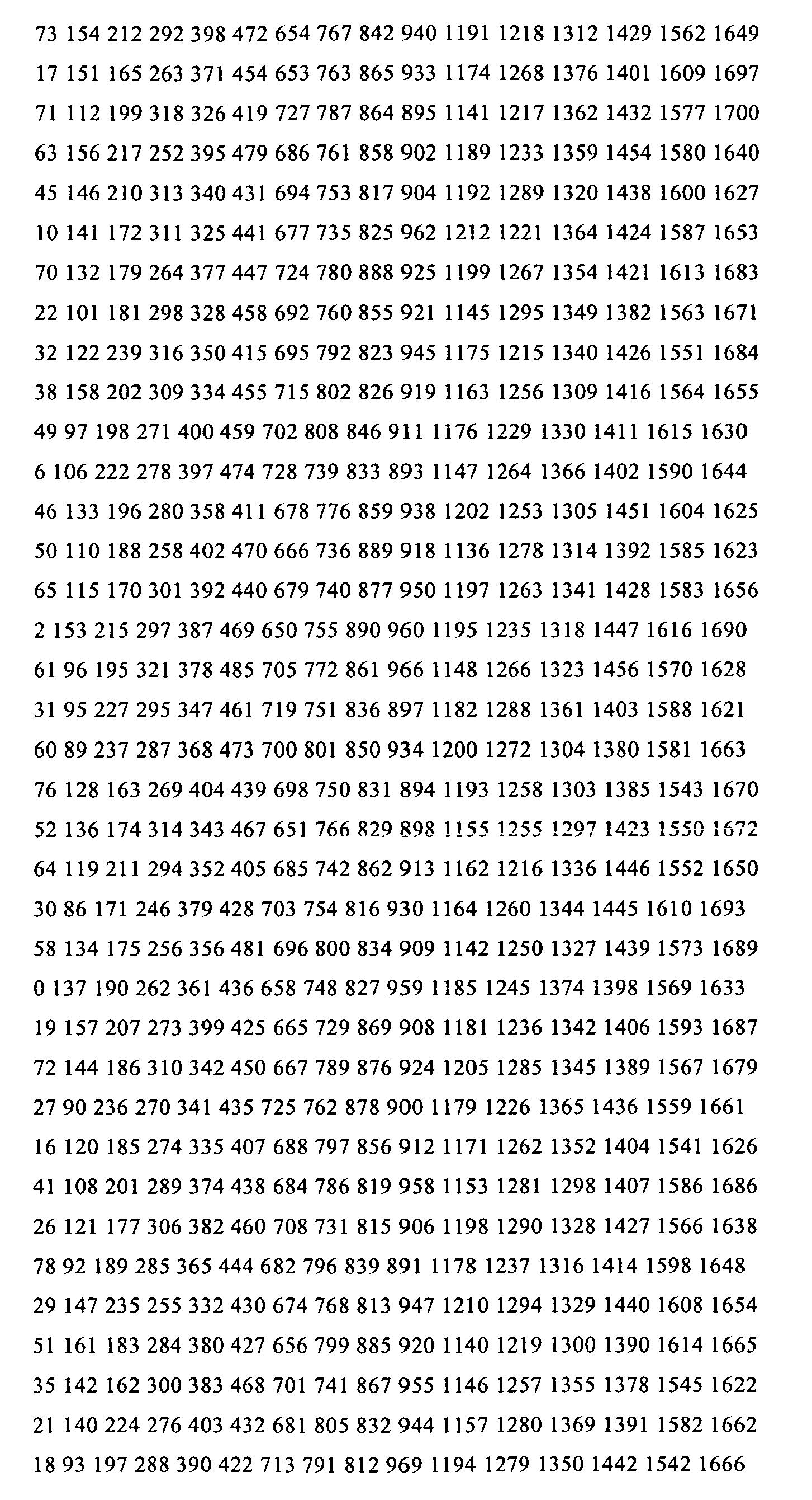


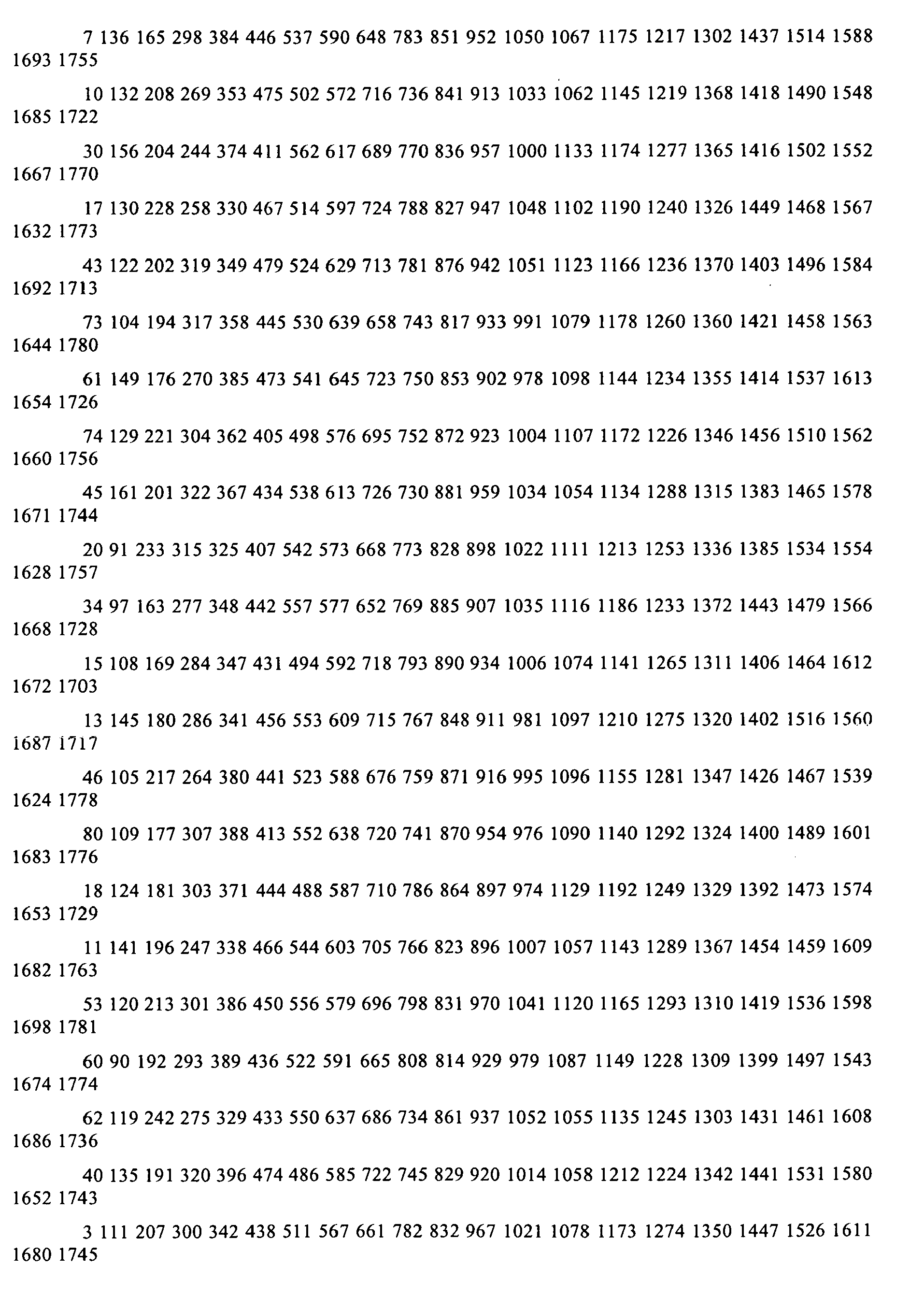


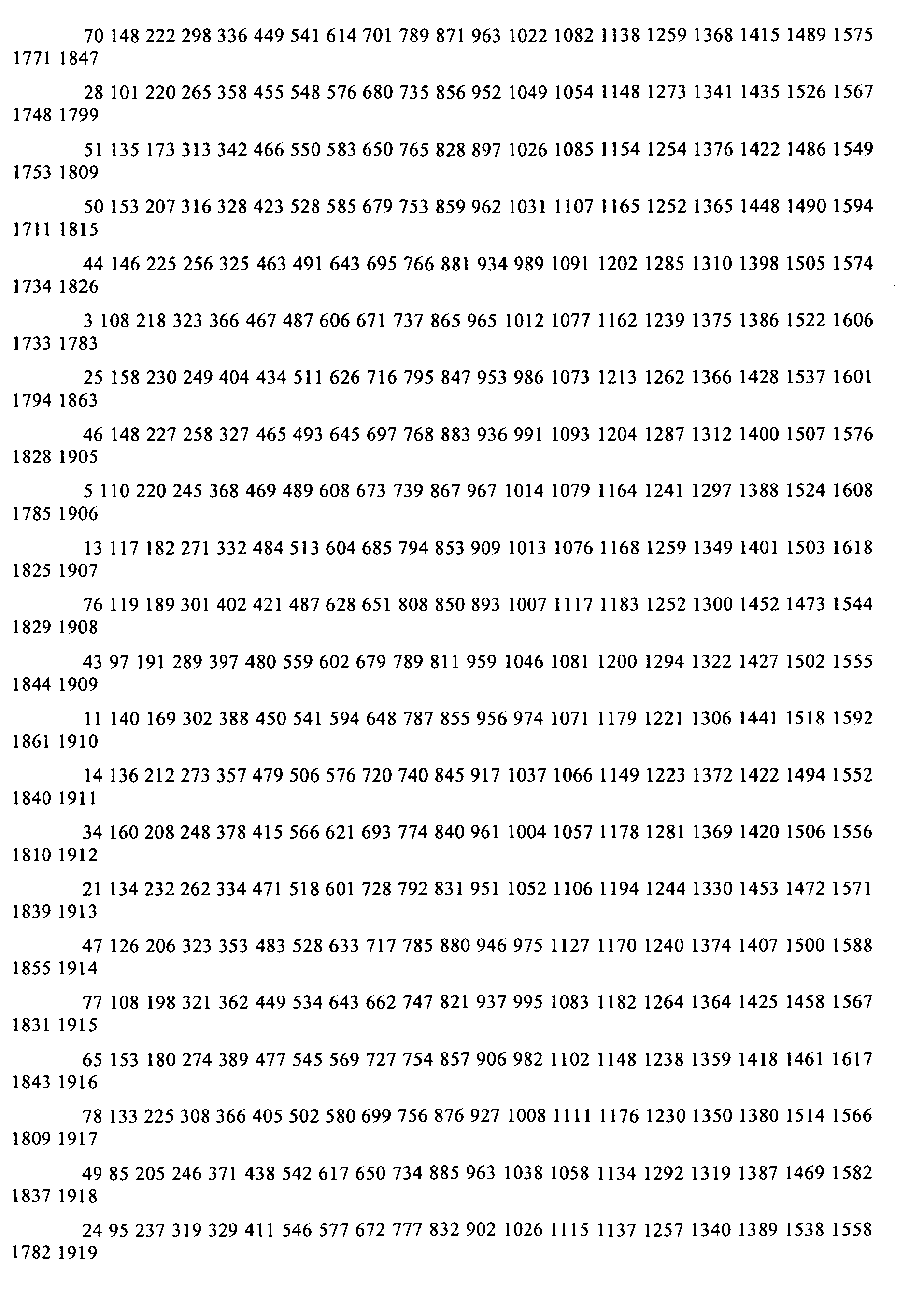

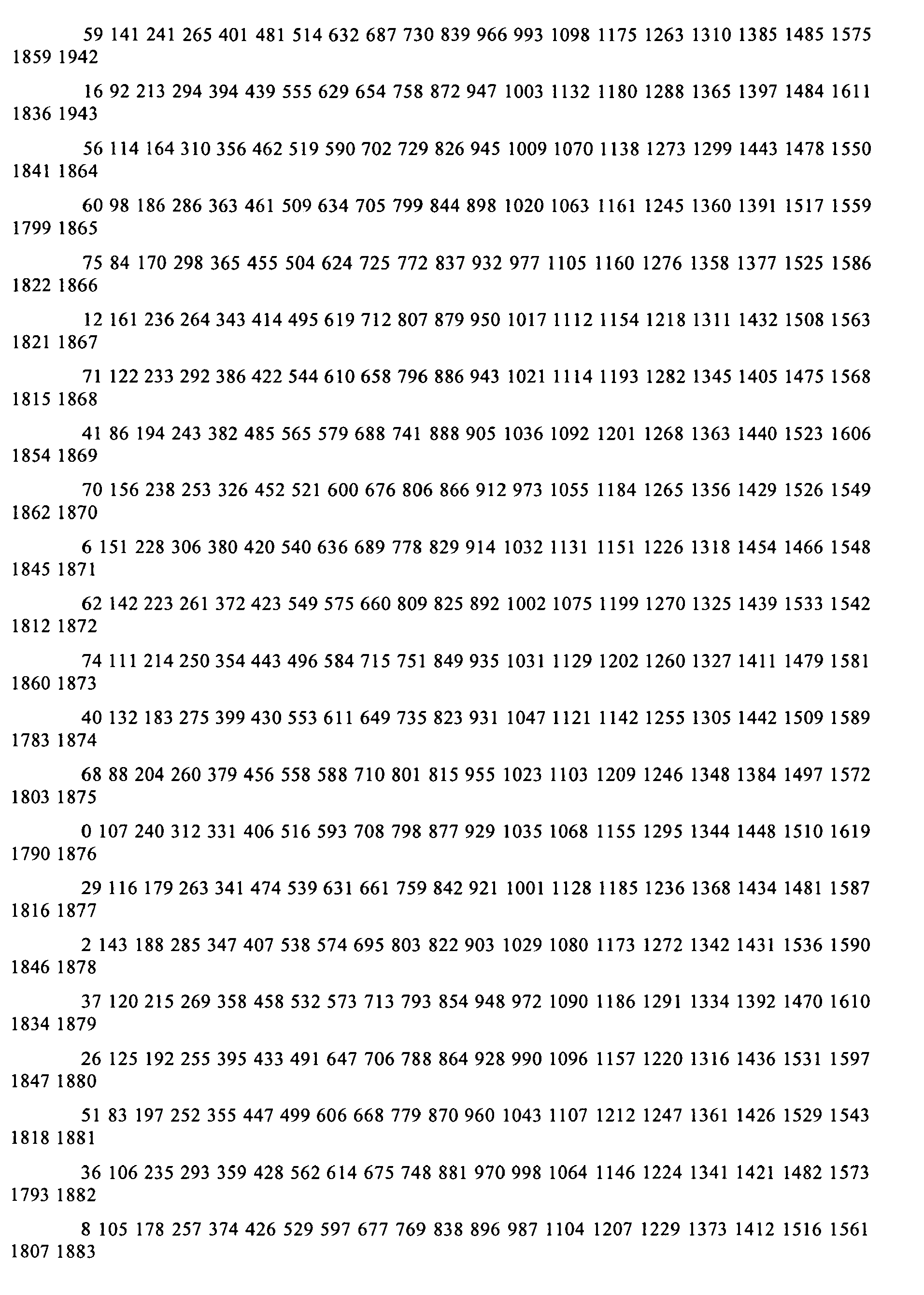

Claims (10)
- A method for constructing a parity check matrix that corresponds to a GRS (Generalized Reed-Solomon)-based irregular LDPC (Low Density Parity Check) code, the method comprising:choosing a plurality of possible bit degree distributions for an LDPC code block;selecting a bit degree distribution from among the plurality of possible bit degree distributions, wherein the selected bit degree distribution has a best performance threshold among the plurality of possible bit degree distributions;decomposing a parity check matrix that corresponds to a GRS-based regular LDPC code into a plurality of partial-matrices based on the selected bit degree distribution, wherein each partial-matrix of the plurality of partial-matrices has a corresponding bit degree and each partial-matrix of the plurality of partial-matrices has a corresponding plurality of permutation matrices; andreplacing at least one permutation matrix within at least one partial-matrix of the plurality of partial-matrices with a zero matrix thereby generating a parity check matrix that corresponds to a GRS-based irregular LDPC code.
- The method of claim 1, further comprising:performing a density evolution method analysis to each bit degree distribution of the plurality of possible bit degree distributions thereby generating a plurality of corresponding density evolution method analysis resultants; andselecting the bit degree distribution from among the plurality of possible bit degree distributions by comparing the density evolution method analysis resultants.
- The method of claim 1, wherein:the plurality of partial-matrices comprises three partial-matrices.
- The method of claim 4, further comprising:replacing at least one permutation matrix within a first partial-matrix of the three partial-matrices with a zero matrix; andreplacing at least one permutation matrix within a second partial-matrix of the three partial-matrices with a zero matrix.
- The method of claim 1, further comprising:generating at least one additional parity check matrix that corresponds to at least one additional GRS-based irregular LDPC code;determining a first performance, in terms of BLER (Block Error Rate) as a function of SNR (Signal to Noise Ratio), corresponding to the GRS-based irregular LDPC code as applied to a communication channel;determining a second performance, in terms of BLER as a function of SNR, corresponding to the at least one additional GRS-based irregular LDPC code as applied to the communication channel; andselecting the GRS-based irregular LDPC code when the first performance has a lower error floor than the second performance; andselecting the at least one additional GRS-based irregular LDPC code when the second performance has a lower error floor than the first performance.
- A method for selecting a GRS (Generalized Reed-Solomon)-based irregular LDPC (Low Density Parity Check) code, the method comprising:constructing a plurality of parity check matrices that corresponds to a plurality of GRS-based irregular LDPC codes;determining a plurality of performances, in terms of BLER (Block Error Rate) as a function of SNR (Signal to Noise Ratio), that corresponds to each GRS-based irregular LDPC code of the plurality of GRS-based irregular LDPC codes as applied to a communication channel; andselecting a GRS-based irregular LDPC code, having a corresponding parity check matrix, from among the plurality of GRS-based irregular LDPC codes having a lowest error floor as determined from the plurality of performances.
- The method of claim 6, further comprising:considering a complexity of a first decoder to be implemented to decode signals coded according to a first GRS-based irregular LDPC code of the plurality of GRS-based irregular LDPC codes;considering a complexity of a second decoder to be implemented to decode signals coded according to a second GRS-based irregular LDPC code of the plurality of GRS-based irregular LDPC codesselecting the first GRS-based irregular LDPC code when the complexity of the first decoder is less than the complexity of the second decoder; andselecting the second GRS-based irregular LDPC code when the complexity of the second decoder is less than the complexity of the first decoder.
- The method of claim 6, wherein:a parity check matrix of the plurality of parity check matrices comprises a first partial-matrix and a second partial-matrix; andat least one permutation matrix within the second partial-matrix is replaced with a zero matrix.
- A method for constructing a parity check matrix that corresponds to a GRS (Generalized Reed-Solomon)-based irregular LDPC (Low Density Parity Check) code, the method comprising:decomposing a parity check matrix that corresponds to a GRS-based regular LDPC code into a plurality of partial-matrices based on a bit degree distribution, wherein each partial-matrix of the plurality of partial-matrices has a corresponding bit degree and each partial-matrix of the plurality of partial-matrices has a corresponding plurality of permutation matrices; andreplacing at least one permutation matrix within at least one partial-matrix of the plurality of partial-matrices with a zero matrix thereby generating a parity check matrix that corresponds to a GRS-based irregular LDPC code.
- The method of claim 9, further comprising:choosing a plurality of possible bit degree distributions for an LDPC code block;selecting the bit degree distribution from among the plurality of possible bit degree distributions, wherein the selected bit degree distribution has a best performance threshold among the plurality of possible bit degree distributions; and wherein:the GRS-based regular LDPC code has a minimum distance; andthe GRS-based irregular LDPC code also has the minimum distance.
Applications Claiming Priority (4)
| Application Number | Priority Date | Filing Date | Title |
|---|---|---|---|
| US64268905P | 2005-01-10 | 2005-01-10 | |
| US67408405P | 2005-04-22 | 2005-04-22 | |
| US67534605P | 2005-04-27 | 2005-04-27 | |
| US11/264,997 US7549105B2 (en) | 2005-01-10 | 2005-11-02 | Construction of irregular LDPC (low density parity check) codes using RS (Reed-Solomon) codes or GRS (generalized Reed-Solomon) code |
Publications (1)
| Publication Number | Publication Date |
|---|---|
| EP1679801A1 true EP1679801A1 (en) | 2006-07-12 |
Family
ID=40740013
Family Applications (1)
| Application Number | Title | Priority Date | Filing Date |
|---|---|---|---|
| EP20050028437 Ceased EP1679801A1 (en) | 2005-01-10 | 2005-12-23 | Construction of irregular LDPC (Low Density Parity Check) codes using RS (Reed-Solomon) codes or GRS (Generalized Reed-Solomon) code |
Country Status (3)
| Country | Link |
|---|---|
| US (1) | US7549105B2 (en) |
| EP (1) | EP1679801A1 (en) |
| TW (1) | TWI330470B (en) |
Families Citing this family (10)
| Publication number | Priority date | Publication date | Assignee | Title |
|---|---|---|---|---|
| US7516390B2 (en) * | 2005-01-10 | 2009-04-07 | Broadcom Corporation | LDPC (Low Density Parity Check) coding and interleaving implemented in MIMO communication systems |
| US7707479B2 (en) | 2005-12-13 | 2010-04-27 | Samsung Electronics Co., Ltd. | Method of generating structured irregular low density parity checkcodes for wireless systems |
| US20070180344A1 (en) * | 2006-01-31 | 2007-08-02 | Jacobsen Eric A | Techniques for low density parity check for forward error correction in high-data rate transmission |
| KR100996030B1 (en) * | 2007-03-06 | 2010-11-22 | 삼성전자주식회사 | Signal transceiving device and method in communication system |
| KR101493999B1 (en) * | 2007-09-06 | 2015-02-17 | 삼성전자주식회사 | Appratus and method for gernerating linear code |
| US8219876B2 (en) | 2007-10-24 | 2012-07-10 | Core Wireless Licensing, S.a.r.l. | Method, apparatus, computer program product and device providing semi-parallel low density parity check decoding using a block structured parity check matrix |
| TWI415396B (en) * | 2009-11-23 | 2013-11-11 | Nat Univ Tsing Hua | Decoder and decoding method for low-density parity check codes constructed based on reed-solomon codes |
| US10382064B2 (en) | 2015-10-13 | 2019-08-13 | SK Hynix Inc. | Efficient LDPC encoder for irregular code |
| US10530395B2 (en) | 2018-02-06 | 2020-01-07 | Alibaba Group Holding Limited | Iterative message-passing decoding with global code embedded with local code in time-division manner for fault tolerance improvement |
| US10977125B2 (en) * | 2019-06-06 | 2021-04-13 | Western Digital Technologies, Inc. | Adaptive usage of irregular code schemas based on specific system level triggers and policies |
Family Cites Families (10)
| Publication number | Priority date | Publication date | Assignee | Title |
|---|---|---|---|---|
| US3542756A (en) | 1968-02-07 | 1970-11-24 | Codex Corp | Error correcting |
| US3665396A (en) | 1968-10-11 | 1972-05-23 | Codex Corp | Sequential decoding |
| US4295218A (en) | 1979-06-25 | 1981-10-13 | Regents Of The University Of California | Error-correcting coding system |
| US4833693A (en) * | 1985-11-21 | 1989-05-23 | Codex Corporation | Coded modulation system using interleaving for decision-feedback equalization |
| US6430233B1 (en) | 1999-08-30 | 2002-08-06 | Hughes Electronics Corporation | Single-LNB satellite data receiver |
| US6473010B1 (en) | 2000-04-04 | 2002-10-29 | Marvell International, Ltd. | Method and apparatus for determining error correction code failure rate for iterative decoding algorithms |
| US6567465B2 (en) | 2001-05-21 | 2003-05-20 | Pc Tel Inc. | DSL modem utilizing low density parity check codes |
| US6633856B2 (en) | 2001-06-15 | 2003-10-14 | Flarion Technologies, Inc. | Methods and apparatus for decoding LDPC codes |
| US7246304B2 (en) | 2001-09-01 | 2007-07-17 | Dsp Group Inc | Decoding architecture for low density parity check codes |
| US7516390B2 (en) * | 2005-01-10 | 2009-04-07 | Broadcom Corporation | LDPC (Low Density Parity Check) coding and interleaving implemented in MIMO communication systems |
-
2005
- 2005-11-02 US US11/264,997 patent/US7549105B2/en not_active Expired - Fee Related
- 2005-12-23 EP EP20050028437 patent/EP1679801A1/en not_active Ceased
-
2006
- 2006-01-09 TW TW095100822A patent/TWI330470B/en not_active IP Right Cessation
Non-Patent Citations (8)
| Title |
|---|
| AMIN SHOKROLLAHI: "LDPC Codes: An Introduction", INTERNET ARTICLE, 2 April 2003 (2003-04-02), XP002360065, Retrieved from the Internet <URL:http://www.ipm.ac.ir/IPM/homepage/Amin2.pdf> [retrieved on 20051219] * |
| CAMPELLO J ET AL: "Designing LDPC codes using bit-filling", ICC 2001. 2001 IEEE INTERNATIONAL CONFERENCE ON COMMUNICATIONS. CONFERENCE RECORD. HELSINKY, FINLAND, JUNE 11 - 14, 2001, IEEE INTERNATIONAL CONFERENCE ON COMMUNICATIONS, NEW YORK, NY : IEEE, US, vol. VOL. 1 OF 10, 11 June 2001 (2001-06-11), pages 55 - 59, XP010552965, ISBN: 0-7803-7097-1 * |
| DJURDJEVIC I ET AL: "A CLASS OF LOW-DENSITY PARTIY-CHECK CODES CONSTRUCTED BASED ON REED-SOLOMON CODES WITH TWO INFORMATION SYMBOLS", IEEE COMMUNICATIONS LETTERS, IEEE SERVICE CENTER, PISCATAWAY, NJ, US, vol. 7, no. 7, July 2003 (2003-07-01), pages 317 - 319, XP001175972, ISSN: 1089-7798 * |
| JONATHAN I. HALL: "Chapter 5: Generalized Reed-Solomon Codes", INTERNET ARTICLE, 3 January 2003 (2003-01-03), XP002360066, Retrieved from the Internet <URL:http://www.math.msu.edu/~jhall/classes/codenotes/GRS.pdf> [retrieved on 20041219] * |
| LEI CHEN ET AL: "Construction of quasi-cyclic LDPC codes based on the minimum weight codewords of reed-solomon codes", INFORMATION THEORY, 2004. ISIT 2004. PROCEEDINGS. INTERNATIONAL SYMPOSIUM ON CHICAGO, ILLINOIS, USA JUNE 27-JULY 2, 2004, PISCATAWAY, NJ, USA,IEEE, 27 June 2004 (2004-06-27), pages 239 - 239, XP010749950, ISBN: 0-7803-8280-3 * |
| MACWILLIAMS F. J. AND N.J.A. SLOANE: "THE THEORY OF ERROR-CORRECTING CODES", 1977, NORTH-HOLLAND MATHEMATICAL LIBRARY, AMSTERDAM, ISBN: 0-444-85193-3, XP002360271 * |
| RICHARDSON T J ET AL: "The capacity of low-density parity-check codes under message-passing decoding", IEEE TRANSACTIONS ON INFORMATION THEORY, IEEE SERVICE CENTER, PISCATAWAY, NJ, US, vol. 47, no. 2, February 2001 (2001-02-01), pages 599 - 618, XP002228426, ISSN: 0018-9448 * |
| SHU LIN: "Structured Low Density Parity Check Codes: Algebraic Constructions", INTERNET ARTICLE, 10 July 2004 (2004-07-10), XP002360064, Retrieved from the Internet <URL:http://www.ieee802.org/3/an/public/jul04/lin_1_0704.pdf> [retrieved on 20051219] * |
Also Published As
| Publication number | Publication date |
|---|---|
| US7549105B2 (en) | 2009-06-16 |
| TW200705827A (en) | 2007-02-01 |
| US20060156168A1 (en) | 2006-07-13 |
| TWI330470B (en) | 2010-09-11 |
Similar Documents
| Publication | Publication Date | Title |
|---|---|---|
| EP1715588B1 (en) | Algebraic construction of LDPC (Low Density Parity Check) codes with corresponding parity check matrix having CSI (Cyclic Shifted Identity) sub-matrices | |
| US8145987B2 (en) | LDPC (low density parity check) codes with corresponding parity check matrices selectively constructed with CSI (cyclic shifted identity) and null sub-matrices | |
| US8341492B2 (en) | Quasi-cyclic LDPC (low density parity check) code construction | |
| US9692451B2 (en) | Non-binary low density parity check (NB-LDPC) codes for communication systems | |
| US8392787B2 (en) | Selective merge and partial reuse LDPC (Low Density Parity Check) code construction for limited number of layers Belief Propagation (BP) decoding | |
| US20060156169A1 (en) | LDPC (Low Density Parity Check) coding and interleaving implemented in MIMO communication systems | |
| US8386906B2 (en) | Multi-CSI (cyclic shifted identity) sub-matrix based LDPC (low density parity check) codes | |
| US7774689B2 (en) | Encoding and decoding methods and systems | |
| HK1217840A1 (en) | Non-binary low density parity check (nb-ldpc) codes for communication systems | |
| US7549105B2 (en) | Construction of irregular LDPC (low density parity check) codes using RS (Reed-Solomon) codes or GRS (generalized Reed-Solomon) code | |
| US7536629B2 (en) | Construction of LDPC (Low Density Parity Check) codes using GRS (Generalized Reed-Solomon) code | |
| US20110202814A1 (en) | Interleaving scheme for an ldpc coded 32 apsk system | |
| US7458003B2 (en) | Low-complexity, capacity-achieving code for communication systems | |
| US7559010B2 (en) | Short length LDPC (Low Density Parity Check) code and modulation adapted for high speed Ethernet applications | |
| CN101150551B (en) | Interweaving scheme of QPSK/8PSK system for low-density checksum coding | |
| CN101150378B (en) | Interleaving scheme of 32APSK system for low-density checksum coding | |
| CN101150550A (en) | Interleaving scheme of LDPC coded 16APSK system | |
| HK1118989A (en) | An interleaving scheme for an ldpc coded 32apsk system | |
| HK1118991A (en) | An interleaving scheme for an ldpc coded qpsk/8psk system | |
| HK1118990A (en) | An interleaving scheme for an ldpc coded 16apsk system |
Legal Events
| Date | Code | Title | Description |
|---|---|---|---|
| PUAI | Public reference made under article 153(3) epc to a published international application that has entered the european phase |
Free format text: ORIGINAL CODE: 0009012 |
|
| AK | Designated contracting states |
Kind code of ref document: A1 Designated state(s): AT BE BG CH CY CZ DE DK EE ES FI FR GB GR HU IE IS IT LI LT LU LV MC NL PL PT RO SE SI SK TR |
|
| AX | Request for extension of the european patent |
Extension state: AL BA HR MK YU |
|
| 17P | Request for examination filed |
Effective date: 20070112 |
|
| AKX | Designation fees paid |
Designated state(s): DE FR GB |
|
| 17Q | First examination report despatched |
Effective date: 20070301 |
|
| RAP1 | Party data changed (applicant data changed or rights of an application transferred) |
Owner name: BROADCOM CORPORATION |
|
| STAA | Information on the status of an ep patent application or granted ep patent |
Free format text: STATUS: THE APPLICATION HAS BEEN REFUSED |
|
| 18R | Application refused |
Effective date: 20151111 |