EP1679762A1 - Radio apparatus - Google Patents
Radio apparatus Download PDFInfo
- Publication number
- EP1679762A1 EP1679762A1 EP05104500A EP05104500A EP1679762A1 EP 1679762 A1 EP1679762 A1 EP 1679762A1 EP 05104500 A EP05104500 A EP 05104500A EP 05104500 A EP05104500 A EP 05104500A EP 1679762 A1 EP1679762 A1 EP 1679762A1
- Authority
- EP
- European Patent Office
- Prior art keywords
- antenna element
- frequency
- antenna
- radio apparatus
- path
- Prior art date
- Legal status (The legal status is an assumption and is not a legal conclusion. Google has not performed a legal analysis and makes no representation as to the accuracy of the status listed.)
- Granted
Links
Images






Classifications
-
- H—ELECTRICITY
- H01—ELECTRIC ELEMENTS
- H01Q—ANTENNAS, i.e. RADIO AERIALS
- H01Q9/00—Electrically-short antennas having dimensions not more than twice the operating wavelength and consisting of conductive active radiating elements
- H01Q9/04—Resonant antennas
- H01Q9/16—Resonant antennas with feed intermediate between the extremities of the antenna, e.g. centre-fed dipole
- H01Q9/26—Resonant antennas with feed intermediate between the extremities of the antenna, e.g. centre-fed dipole with folded element or elements, the folded parts being spaced apart a small fraction of operating wavelength
-
- H—ELECTRICITY
- H01—ELECTRIC ELEMENTS
- H01Q—ANTENNAS, i.e. RADIO AERIALS
- H01Q5/00—Arrangements for simultaneous operation of antennas on two or more different wavebands, e.g. dual-band or multi-band arrangements
- H01Q5/30—Arrangements for providing operation on different wavebands
- H01Q5/307—Individual or coupled radiating elements, each element being fed in an unspecified way
- H01Q5/342—Individual or coupled radiating elements, each element being fed in an unspecified way for different propagation modes
- H01Q5/357—Individual or coupled radiating elements, each element being fed in an unspecified way for different propagation modes using a single feed point
- H01Q5/364—Creating multiple current paths
-
- H—ELECTRICITY
- H01—ELECTRIC ELEMENTS
- H01Q—ANTENNAS, i.e. RADIO AERIALS
- H01Q5/00—Arrangements for simultaneous operation of antennas on two or more different wavebands, e.g. dual-band or multi-band arrangements
- H01Q5/30—Arrangements for providing operation on different wavebands
- H01Q5/307—Individual or coupled radiating elements, each element being fed in an unspecified way
- H01Q5/342—Individual or coupled radiating elements, each element being fed in an unspecified way for different propagation modes
- H01Q5/357—Individual or coupled radiating elements, each element being fed in an unspecified way for different propagation modes using a single feed point
- H01Q5/364—Creating multiple current paths
- H01Q5/371—Branching current paths
-
- H—ELECTRICITY
- H01—ELECTRIC ELEMENTS
- H01Q—ANTENNAS, i.e. RADIO AERIALS
- H01Q5/00—Arrangements for simultaneous operation of antennas on two or more different wavebands, e.g. dual-band or multi-band arrangements
- H01Q5/30—Arrangements for providing operation on different wavebands
- H01Q5/378—Combination of fed elements with parasitic elements
-
- H—ELECTRICITY
- H01—ELECTRIC ELEMENTS
- H01Q—ANTENNAS, i.e. RADIO AERIALS
- H01Q9/00—Electrically-short antennas having dimensions not more than twice the operating wavelength and consisting of conductive active radiating elements
- H01Q9/04—Resonant antennas
- H01Q9/30—Resonant antennas with feed to end of elongated active element, e.g. unipole
- H01Q9/42—Resonant antennas with feed to end of elongated active element, e.g. unipole with folded element, the folded parts being spaced apart a small fraction of the operating wavelength
Definitions
- the present invention relates to a radio apparatus having an antenna.
- radio apparatuses like mobile phones have internal antennas rather than those to be pulled out of their cases when used, like flexible whip antennas.
- Using internal antennas for radio apparatuses greatly facilitates their handling or holding and increases a degree of flexibility of their case design, particularly using a thinner case.
- a conventional radio apparatus having an internal antenna in a small case may cause decreasing the antenna input impedance as the antenna is located very close to metallic portions of surrounding circuits within the case. That may cause a mismatch between the antenna and its feeder circuit to degrade a performance of the radio apparatus.
- a conventional, named folded dipole antenna may be used not to decrease the antenna input impedance too much.
- Two or more dipole elements are placed in parallel very closely to configure a folded dipole antenna.
- An end of one of the dipole elements is connected to an end of the rest of them and so are the other ends, and one of them is fed at a central feeding point. It is usually configured symmetric about the feeding point.
- This folded dipole antenna is disclosed, for example, in the following document: "Antenna Engineering Handbook", pp. 112-113, Figures 4.1 and 4.3 (in Japanese), edited by The Institute of Electronics, Information and Communication Engineers, Ohm-sha, October 1996.
- a folded dipole antenna may have impedance higher than a simple dipole antenna without being folded, and the value of impedance may be adjusted by the ratio of diameters of the dipole elements placed in parallel.
- a dipole antenna does not fit a small-sized radio apparatus, particularly one of multiple functions leaving limited space to enclose an antenna, by nature due to its size.
- a folded dipole antenna may be even worse due to its complicated shape.
- a radio apparatus of multiple uses or of multiple standards these days is required to have an antenna of a wider range.
- Plural antenna elements of various resonant frequencies need to be assembled to form an antenna of multi-frequency resonance.
- Each antenna element is thereby required to be smaller in size and simpler in shape than, for example, the folded dipole type.
- One half of a folded dipole antenna configured symmetric can be used as a monopole antenna fed at its one end and grounded at the other end.
- This is called a folded monopole antenna, equivalent to the folded dipole antenna in electrical features except for having half the input impedance of the folded dipole antenna, and its application to small-sized radio apparatuses is being studied.
- Sato, K. and Amano, T "Dual-band folded antenna with two shorted points"
- IEICE General Conference B-1-57 in Japanese
- the Institute of Electronics, Information and Communication Engineers March 2004.
- This "dual-band folded antenna” is configured to have two resonant frequencies as an assembly of a pair of folded monopole antenna elements of a rather low-profile type so called inverted-L, each of which has its own resonant frequency. Advantages of this configuration are showing a feature of multi-frequency resonance, fitting a radio apparatus of a thinner case, and facilitating matching impedance of the one element by short-circuiting the forward and backward paths of the other element at a point on those paths.
- This configuration still has a disadvantage that needs two or more folded antenna elements to be assembled, and may not fit a small-sized radio apparatus of multiple functions, particularly for present and future use, leaving limited space to enclose an antenna.
- an advantage of the present invention is to provide a radio apparatus having an antenna producing multi-frequency resonance and capable of matching impedance and being enclosed in limited space within the case.
- a radio apparatus usable in a frequency band comprising a feeder circuit, a first antenna element and a second antenna element.
- the first antenna element has a first end connected to the feeder circuit and a second end, folds back at a folding portion to include a forward path from the first end to the folding portion and a backward path from the folding portion to the second end, and is a half wavelength long of a first frequency in the frequency band.
- the second end is grounded and located no farther than one-tenth wavelength of the first frequency away from the first end.
- the forward path and the backward path short-circuit at a shorting bridge.
- the second antenna element begins with the first end, shares a part of the forward path with the first antenna element, diverges from the forward path at a diverging point between the first end and the shorting bridge, comes to an open end, and is one-fourth wavelength long of a second frequency in the frequency band.
- FIG. 1 illustrates a configuration of a main part of a radio apparatus 1 in the first embodiment.
- the radio apparatus 1 is usable in a frequency band i.e., a band of use.
- the radio apparatus 1 has a feeder circuit 10, a first antenna element 20 and a second antenna element 30.
- the feeder circuit 10 has a radio circuit 11 and a feeder line 12.
- the radio circuit 11 has either or both a transmitter and a receiver that are not shown.
- the first antenna element 20 and the second antenna element 30 shares a part of them, which will be described in detail later with reference to FIG. 4.
- the radio apparatus 1 has a case like ordinary radio apparatuses. Other components like a speaker, a microphone, a display, a control circuit and so forth are not shown either.
- the radio apparatus 1 has a printed board 40.
- the feeder circuit 10 is mounted on the printed board 40, and the first antenna element 20 and the second antenna element 30 are attached to the printed board 40.
- Including the printed board 40 in this configuration makes the description easier to comprehend as radio apparatuses usually have printed boards.
- the first antenna element 20 has two ends, a first end 21 and a second end 22.
- the first end 21 is connected to the feeder line 12 and it is thereby a feeding point of the first antenna element 20.
- the second end 22 is grounded on the printed board 40.
- the distance between the first end 21 and the second end 22 has an upper limit as the first antenna element 20 is a kind of folded monopole antennas, which will be described later with reference to FIG. 2.
- FIG. 2 illustrates a configuration of the first antenna element in the first embodiment. Parts belonging only to the second antenna element 30 in FIG. 1 are not shown in FIG. 2 to highlight the configuration of the first antenna element 20.
- the hatched part of FIG. 2 is the first antenna element 20.
- Each component given the reference numeral 1, 11, 21, 22 or 40 is the same as the corresponding one shown in FIG. 1 and its explanation is omitted.
- the first antenna element 20 begins with the first end 21, folds back at a folding portion 23 and reaches the second end 22 to be grounded. A part of the first antenna element 20 from the first end 21 to the folding portion 23 is a forward path 24. A part of the first antenna element 20 from the folding portion 23 to the second end 22 is a backward path 25.
- the length of the first antenna element 20 from the first end 21, along the forward path 24, via the folding portion 23, along the backward path 25, and to the second end 22 is a half wavelength of a first frequency in the band of use (refer to Note 1 of FIG. 2).
- the forward path 24 and the backward path 25 are placed close to each other, and the second end 22 is located no farther than one-tenth wavelength of the first frequency away from the first end 21 (refer to Note 2 of FIG. 2).
- the first antenna element 20 is thus configured to be a folded monopole antenna and produces resonance at the first frequency.
- the upper limit of the distance between the first end 21 and the second end 22 of one-tenth wavelength of the resonant frequency stems from technical experiences based on which the configuration works as a folded monopole antenna.
- the forward path 24 and the backward path 25 short-circuit at a shorting bridge 26. An effect of this short-circuiting will be described later with reference to FIG. 5.
- the first antenna element 20 includes a returning path 27 which will be described with reference to FIG. 3.
- FIG. 3 illustrates a configuration of the returning path 27.
- the part drawn filled with black in FIG. 3 is the returning path 27.
- Each component given the reference numeral 1, 11, 12, 21, 22, 23, 26 or 40 is the same as the corresponding one shown in FIG. 2 and its explanation is omitted.
- the returning path 27 begins with the first end 21, returns at the shorting bridge 26 and reaches the second end 22.
- the returning path 27 is formed by a part of the forward path 24 from the first end 21 to the shorting bridge 26 and a part of the backward path 25 from the shorting bridge 26 to the second end 22.
- FIG. 4 illustrates a configuration of a second antenna element 30 in the first embodiment.
- the part drawn filled with black in FIG. 4 is the second antenna element 30.
- Each component given the reference numeral 1, 11, 12, 21, 22, 23, 26 or 40 is the same as the corresponding one shown in FIG. 2 and its explanation is omitted.
- the second antenna element 30 shares a part of the forward path 24 from the first end 21 to a diverging point 28 between the first end 21 and the shorting bridge 26 with the first antenna element 20, diverges from the forward path 24 at the diverging point 28 and has an open end 31.
- the length of the second antenna element 30 from the first end 21 via the diverging point 28 to the open end 31 is one-fourth wavelength of a second frequency in the band of use (refer to Note of FIG. 4).
- the second antenna element 30 is thus configured to be a monopole antenna and produces resonance at the second frequency. Setting the second frequency to a value different from the first frequency gives the radio apparatus 1 two antenna resonant frequencies and thus may broaden its antenna frequency range.
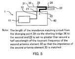
- FIG. 5 illustrates a configuration of a portion of the returning path 27 which begins with the diverging point 28, returns at the shorting bridge 26 and reaches the second end 22, and is drawn filled with black in FIG. 5.
- This portion works as an impedance matching circuit of the second antenna element 30 in the first embodiment.
- the shorting bridge 26 is basically positioned in the first antenna element 20 so that the impedance matching circuit is around a half wavelength long of the second frequency.
- the shorting bridge 26 may be positioned no farther to the first end 21 than the above basic position. The nearer the shorting bridge 26 is positioned to the first end 21, the higher the input impedance of the second antenna element 30 becomes.
- the length of the impedance matching circuit may be set to an appropriate value no greater than around a half wavelength of the resonant frequency of the second antenna element 30 so that its impedance is matched (refer to Note of FIG. 5).
- a combination of a folded monopole antenna with shorting its forward and backward paths and an ordinary, simply shaped monopole antenna gives the radio apparatus two-frequency resonance and impedance matching of its antenna at the same time, and makes the radio apparatus capable of being enclosed in limited space.
- a radio apparatus in the second embodiment adopts the same configuration as the one in the first embodiment shown in FIG. 1 through FIG. 5 except that the lengths of the first and second antenna elements, the distance between the first end and the second end, and the length of a portion of the returning path working as an impedance matching circuit of the second antenna element are given different definitions.
- Each component of the second embodiment is thus given the same reference numeral as the corresponding one shown in the first embodiment.
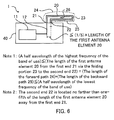
- FIG. 6 illustrates a configuration of a first antenna element 20 in the second embodiment, like FIG. 2 in the first embodiment. Every component shown in FIG. 6 is the same as the corresponding one shown in FIG. 2 given the same reference numeral and its explanation is omitted.
- the length of the first antenna element 20 from the first end 21 via the folding portion 23 to the second end 22 is selected as a half wavelength of a desired frequency in the band of use. It may be defined to be no less than a half wavelength of the highest frequency of the band of use and no greater than a half wavelength of the lowest frequency of the band of use (refer to Note 1 of FIG. 6).
- the distance between the first end 21 and the second end 22 needs a definition different from the one in the first embodiment.
- a definition that the distance is no greater than one fifth of the length of the first antenna element is equivalent to its definition in the first embodiment (refer to Note 2 of FIG. 6).
- FIG. 7 illustrates a configuration of a second antenna element 30 in the second embodiment, like FIG. 4 in the first embodiment. Every component shown in FIG. 7 is the same as the corresponding one shown in FIG. 4 given the same reference numeral and its explanation is omitted.
- the length of the second antenna element 30 from the first end 21 via the diverging point 28 to the open end 31 is selected as one-fourth wavelength of another desired frequency in the band of use. It may be defined to be no less than one-fourth wavelength of the highest frequency of the band of use and no greater than one-fourth wavelength of the lowest frequency of the band of use (refer to Note of FIG. 7).
- FIG. 8 illustrates a configuration of a portion of the returning path 27 from the diverging point 28, via the shorting bridge 26 to the second end 22, working as an impedance matching circuit of the second antenna element 30 in the second embodiment, like FIG. 5 in the first embodiment. Every component shown in FIG. 8 is the same as the corresponding one shown in FIG. 5 given the same reference numeral and its explanation is omitted.
- the length of the impedance matching circuit needs a definition different from the one in the first embodiment.
- a definition that the shorting bridge 26 is basically positioned in the first antenna element 20 so that the impedance matching circuit is twice as long as the second antenna element 30 and that the shorting bridge 26 may be positioned no farther to the first end 21 than the above basic position is equivalent to its definition in the first embodiment (refer to Note of FIG. 8).
- FIG. 9 illustrates a configuration of a main part of a radio apparatus 5 in a third embodiment of the present invention.
- the radio apparatus 5 is usable in a frequency band of use.
- the radio apparatus 5 has a feeder circuit 50 that includes a radio circuit 51 and a feeder line 52.
- the radio circuit 51 has either or both a transmitter and a receiver that are not shown.
- the radio apparatus 5 has a first antenna element 55. It begins with a first end 56 connected to the feeder line 52, goes via a diverging point 57 and a bending portion 58, folds back at a folding portion 59 and then reaches a second end 60 to be grounded.
- the first antenna element 55 has a forward path from the first end 56 to the folding portion 59, and a backward path from the folding portion 59 to the second end 60.
- the sum of the lengths of the forward path and the backward path is a half wavelength of a first frequency in the band of use.
- the forward path and the backward path are placed close to each other, and the second end 60 is positioned no farther than one-tenth wavelength of the first frequency away from the first end 56.
- the first antenna element 55 is thus configured to be a folded monopole antenna and produces resonance at the first frequency.
- the forward path and the backward path short-circuit at a shorting bridge 61.
- the first antenna element 55 includes a returning path that begins with the first end 56, folds back at the shorting bridge 61 and reaches the second end 60.
- the radio apparatus 5 has a second antenna element 65 that shares a part of the first antenna element 55 between the first end 56 and the diverging point 57, diverges at the diverging point 57 and reaches an open end 66.
- the length of the second antenna element 65 from the first end 56 via the diverging point 57 to the open end 66 is one-fourth wavelength of a second frequency in the band of use.
- the second antenna element 65 is thus configured to be a monopole antenna and produces resonance at the second frequency. Setting the second frequency to a value different from the first frequency gives the radio apparatus 5 two antenna resonant frequencies and thus may broaden its antenna frequency range.
- a portion of the returning path from the diverging point 57, via the shorting bridge 61 to the second end 60 works as an impedance matching circuit of the second antenna element 65.
- the shorting bridge 61 is basically positioned in the first antenna element 55 so that the impedance matching circuit is around a half wavelength long of the second frequency.
- the shorting bridge 61 may be positioned no farther to the first end 56 than the above basic position to adjust the impedance matching of the second antenna element 65.
- the length of the impedance matching circuit may be set to an appropriate value no greater than around a half wavelength of the resonant frequency of the second antenna element 65 so that its impedance is matched in a manner similar to the first embodiment.
- the feeder circuit 50 is mounted on a printed board 70.
- the first antenna element 55 and the second antenna element 65 are attached to the printed board 70.
- the printed board 70, the first antenna element 55 and the second antenna element 65 are enclosed within a case 75 of the radio apparatus 5.
- a dashed line enclosing the components stated above shows the case 75.
- the shapes of the first antenna element 55 and the second antenna element 65 are arranged to be enclosed within the case 75, thus both turned to the same direction and the former bent at the bending portion 58. As this configuration shown in FIG. 9 is just an example, those antenna elements may be shaped in a more complicated manner due to the shape of the case 75 and other arrangement factors.
- An advantage of the radio apparatus 5 is to enclose the first antenna element 55 and the second antenna element 65 within the case 75 under various constraints regarding the arrangement therein.
- a combination of a folded monopole antenna with shorting its forward and backward paths and an ordinary, simply shaped monopole antenna may increase a degree of freedom of radio apparatus designs.
- the lengths and arrangements of the antenna elements may be defined in a manner similar to the second embodiment.
- the length of the first antenna element 55 from the first end 56 via the diverging point 57, the bending portion 58 and the folding portion 59 to the second end 60 may be defined no less than a half wavelength of the highest frequency of the band of use and no greater than a half wavelength of the lowest frequency of the band of use.
- the distance between the first end 56 and the second end 60 may be defined to be no greater than one fifth of the length of the first antenna element 55.
- the length of the second antenna element 65 from the first end 56 via the diverging point 57 to the open end 66 may be defined to be no less than one-fourth wavelength of the highest frequency of the band of use and no greater than one-fourth wavelength of the lowest frequency of the band of use.
- the impedance matching circuit from the diverging point 57 via the shorting bridge 61 to the second end 60 may be defined to be no greater than around twice as long as the second antenna element 65 so that the input impedance of the second antenna element 65 is matched.
- a combination of a folded monopole antenna and a simply shaped monopole antenna has another advantage of being enclosed in limited space within a case of a radio apparatus, as well as two-frequency resonance and impedance matching.
- a fourth embodiment of the present invention will be described with reference to FIG. 10 through FIG. 19.
- the fourth embodiment shows variations of the shapes and arrangements of the antenna elements described in the previous embodiments.
- a first antenna element is given a reference numeral 81
- a second antenna element is given 82
- a first end of the first antenna element 81 to be fed is given 83
- a second end of the first antenna element 81 to be grounded is given 84.
- Folding back, short-circuiting and diverging of each antenna element are the same as those of the previous embodiments and explanations of them are omitted.
- FIG. 10 shows a meander-shaped second antenna element 82 that meets a requirement of enclosing the second antenna element 82 having a lower resonant frequency within limited space.
- FIG. 11 shows a first antenna element 81 and a second antenna element 82 attached to a printed board 85.
- the first antenna element 81 folds back in a plane parallel to the printed board 85. This configuration fits a thinner case of a radio apparatus.
- FIG. 12 shows a first antenna element 81 and a second antenna element 82 formed on a piece of dielectric material 86 shown with hatching. This configuration allows smaller sizes of the first antenna element 81 and the second antenna element 82 due to a wavelength shortening effect of the dielectric material.
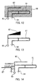
- FIG. 13 shows a second antenna element 82 of a gradually varying width. This configuration contributes to developing a broader frequency range of the antenna configured by the first and the second antenna elements 81 and 82.
- FIG. 14 shows a parasitic element 87 the one end of which is open and the other end is grounded and current-coupled to a first antenna element 81 or a second antenna element 82.
- the length of the parasitic element 87 is one-fourth wavelength of another resonant frequency to contribute to developing multi-frequency resonance.
- FIG. 15 shows a parasitic element 87 the one end of which is grounded and the other end is open and voltage-coupled to a first antenna element 81 or a second antenna element 82.
- the length of the parasitic element 87 is one-fourth wavelength of another resonant frequency to contribute to developing multi-frequency resonance.
- FIG.16 shows a parasitic element 88 both ends of which are open and one of them is voltage-coupled to a first antenna element 81 or a second antenna element 82.
- the length of the parasitic element 88 is a half wavelength of another resonant frequency to contribute to developing multi-frequency resonance.
- FIG.17 shows a first antenna element 81 and a second antenna element 82 turned to the same direction and the former turned again to its fed or grounded end.
- FIG. 18 shows a meander-shaped second antenna element 82 in the configuration of FIG. 17. Both enable the antenna elements to be enclosed in further limited space, e.g. in mobile phones.
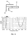
- FIG. 19 shows in the upper drawing a configuration of a first antenna element 81 and a second antenna element 82 turned to the same direction, and in the lower drawing a VSWR-frequency chart simulated in that configuration.
- the plotted curve on the left side of the chart shows a resonance of the first antenna element 81.
- the plotted curve on the right side of the chart shows a resonance of the second antenna element 82.
- variations of the shapes and arrangements of antenna elements contributes to enclosing them in smaller or thinner cases, or to developing multi-frequency resonance.
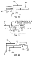
- FIG. 20 shows a parasitic element 90 formed by the parasitic element 87 in FIG. 14 plus a matching circuit 89 inserted in series.
- the matching circuit 89 is, e.g. an inductor.
- FIG. 21 shows an example of how the matching circuit 89 is attached in FIG. 20.
- the feeding point at the first end 83 seen from the first antenna element 81 and the second antenna element 82 includes a radio circuit 91 and matching components 92A, 92B and 92C.
- Those matching components form a matching circuit together for the first antenna element 81 and are mounted on a group of pads placed on a printed board not shown in FIG. 21.
- the matching circuit 89 is mounted on a member of the group of pads.
- the parasitic element 90 with the matching circuit 89 is shorter than the one with no matching circuit, and thus contributes to downsizing. Adjusting the value of the matching circuit 89 enables the resonant frequency of the parasitic element 90 to be fine-tuned.
- FIG. 22 shows a parasitic element 94 formed by the parasitic element 87 in FIG. 15 plus a matching circuit 93 inserted in series.
- Each of the other components is the same as the corresponding one shown in FIG. 15 given the same reference numeral and its explanation is omitted.
- the parasitic element 94 with the matching circuit 93 is shorter than the one with no matching circuit, and thus contributes to downsizing. Adjusting the value of the matching circuit 93 enables the resonant frequency of the parasitic element 94 to be fine-tuned.
- downsized parasitic elements are useful for radio apparatuses of smaller cases and multi-frequency resonance.
Landscapes
- Details Of Aerials (AREA)
- Variable-Direction Aerials And Aerial Arrays (AREA)
- Support Of Aerials (AREA)
Abstract
Description
- This application is based upon and claims the benefit of priority from the prior Japanese Patent Application No. 2005-4061 filed on January 11, 2005;
the entire contents of which are incorporated herein by reference. - The present invention relates to a radio apparatus having an antenna.
- Recently developed radio apparatuses like mobile phones have internal antennas rather than those to be pulled out of their cases when used, like flexible whip antennas. Using internal antennas for radio apparatuses greatly facilitates their handling or holding and increases a degree of flexibility of their case design, particularly using a thinner case.
- A conventional radio apparatus having an internal antenna in a small case may cause decreasing the antenna input impedance as the antenna is located very close to metallic portions of surrounding circuits within the case. That may cause a mismatch between the antenna and its feeder circuit to degrade a performance of the radio apparatus.
- In such circumstances it is known that a conventional, named folded dipole antenna may be used not to decrease the antenna input impedance too much. Two or more dipole elements are placed in parallel very closely to configure a folded dipole antenna. An end of one of the dipole elements is connected to an end of the rest of them and so are the other ends, and one of them is fed at a central feeding point. It is usually configured symmetric about the feeding point. This folded dipole antenna is disclosed, for example, in the following document:
"Antenna Engineering Handbook", pp. 112-113, Figures 4.1 and 4.3 (in Japanese), edited by The Institute of Electronics, Information and Communication Engineers, Ohm-sha, October 1996. - A folded dipole antenna may have impedance higher than a simple dipole antenna without being folded, and the value of impedance may be adjusted by the ratio of diameters of the dipole elements placed in parallel. A dipole antenna, however, does not fit a small-sized radio apparatus, particularly one of multiple functions leaving limited space to enclose an antenna, by nature due to its size. A folded dipole antenna may be even worse due to its complicated shape.
- A radio apparatus of multiple uses or of multiple standards these days is required to have an antenna of a wider range. Plural antenna elements of various resonant frequencies need to be assembled to form an antenna of multi-frequency resonance. Each antenna element is thereby required to be smaller in size and simpler in shape than, for example, the folded dipole type.
- One half of a folded dipole antenna configured symmetric can be used as a monopole antenna fed at its one end and grounded at the other end. This is called a folded monopole antenna, equivalent to the folded dipole antenna in electrical features except for having half the input impedance of the folded dipole antenna, and its application to small-sized radio apparatuses is being studied. An example of such a study is disclosed in the following reference: Sato, K. and Amano, T, "Dual-band folded antenna with two shorted points", IEICE General Conference B-1-57 (in Japanese), The Institute of Electronics, Information and Communication Engineers, March 2004.
- This "dual-band folded antenna" is configured to have two resonant frequencies as an assembly of a pair of folded monopole antenna elements of a rather low-profile type so called inverted-L, each of which has its own resonant frequency. Advantages of this configuration are showing a feature of multi-frequency resonance, fitting a radio apparatus of a thinner case, and facilitating matching impedance of the one element by short-circuiting the forward and backward paths of the other element at a point on those paths.
- This configuration, however, still has a disadvantage that needs two or more folded antenna elements to be assembled, and may not fit a small-sized radio apparatus of multiple functions, particularly for present and future use, leaving limited space to enclose an antenna.
- To solve the technical problem described above, an advantage of the present invention is to provide a radio apparatus having an antenna producing multi-frequency resonance and capable of matching impedance and being enclosed in limited space within the case.
- According to one aspect of the present invention to achieve the above advantage, there is provided a radio apparatus usable in a frequency band comprising a feeder circuit, a first antenna element and a second antenna element.
- The first antenna element has a first end connected to the feeder circuit and a second end, folds back at a folding portion to include a forward path from the first end to the folding portion and a backward path from the folding portion to the second end, and is a half wavelength long of a first frequency in the frequency band. The second end is grounded and located no farther than one-tenth wavelength of the first frequency away from the first end. The forward path and the backward path short-circuit at a shorting bridge.
- The second antenna element begins with the first end, shares a part of the forward path with the first antenna element, diverges from the forward path at a diverging point between the first end and the shorting bridge, comes to an open end, and is one-fourth wavelength long of a second frequency in the frequency band.
-
- FIG. 1 illustrates a configuration of a main part of a radio apparatus in a first embodiment of the present invention.
- FIG. 2 illustrates a configuration of a first antenna element shown in FIG. 1 in the first embodiment.
- FIG. 3 illustrates a configuration of a returning path included in the first antenna element in the first embodiment.
- FIG. 4 illustrates a configuration of a second antenna element shown in FIG. 1 in the first embodiment.
- FIG. 5 illustrates that a portion of the returning path shown in FIG. 3 works as an impedance matching circuit of the second antenna element in the first embodiment.
- FIG. 6 illustrates a configuration of a first antenna element of a second embodiment of the present invention.
- FIG. 7 illustrates a configuration of a second antenna element in the second embodiment.
- FIG. 8 illustrates that a portion of a returning path included in the first antenna element works as an impedance matching circuit of the second antenna element in the second embodiment.
- FIG. 9 illustrates a configuration of a main part of a radio apparatus in a third embodiment of the present invention.
- FIG. 10 illustrates a first variation of an antenna element in a fourth embodiment of the present invention.
- FIG. 11 illustrates a second variation of an antenna element in the fourth embodiment.
- FIG. 12 illustrates a third variation of an antenna element in a fourth embodiment of the present invention.
- FIG. 13 illustrates a fourth variation of an antenna element in the fourth embodiment.
- FIG. 14 illustrates a first example of adding a parasitic element in the fourth embodiment.
- FIG. 15 illustrates a second example of adding a parasitic element in the fourth embodiment.
- FIG. 16 illustrates a third example of adding a parasitic element in the fourth embodiment.
- FIG. 17 illustrates a fifth variation of an antenna element in a fourth embodiment of the present invention.
- FIG. 18 illustrates a sixth variation of an antenna element in the fourth embodiment.
- FIG. 19 illustrates a configuration in the fourth embodiment and a VSWR-frequency chart simulated in that configuration.
- FIG. 20 illustrates an example of downsizing a parasitic element shown in FIG. 14 in a fifth embodiment of the present invention.
- FIG. 21 illustrates an example of how a matching circuit shown in FIG. 20 is attached in the fifth embodiment.
- FIG. 22 illustrates an example of downsizing a parasitic element shown in FIG. 15 in the fifth embodiment.
- A first embodiment of the present invention will be described with reference to FIG. 1 through FIG. 5. FIG. 1 illustrates a configuration of a main part of a
radio apparatus 1 in the first embodiment. Theradio apparatus 1 is usable in a frequency band i.e., a band of use. Theradio apparatus 1 has afeeder circuit 10, afirst antenna element 20 and asecond antenna element 30. Thefeeder circuit 10 has aradio circuit 11 and afeeder line 12. Theradio circuit 11 has either or both a transmitter and a receiver that are not shown. Thefirst antenna element 20 and thesecond antenna element 30 shares a part of them, which will be described in detail later with reference to FIG. 4. - The
radio apparatus 1 has a case like ordinary radio apparatuses. Other components like a speaker, a microphone, a display, a control circuit and so forth are not shown either. - The
radio apparatus 1 has a printedboard 40. Thefeeder circuit 10 is mounted on the printedboard 40, and thefirst antenna element 20 and thesecond antenna element 30 are attached to the printedboard 40. There may be another configuration without the printedboard 40, where thefeeder circuit 10, thefirst antenna element 20 and thesecond antenna element 30 may be attached to, e.g., the case not shown instead. Including the printedboard 40 in this configuration, however, makes the description easier to comprehend as radio apparatuses usually have printed boards. - The
first antenna element 20 has two ends, afirst end 21 and asecond end 22. Thefirst end 21 is connected to thefeeder line 12 and it is thereby a feeding point of thefirst antenna element 20. Thesecond end 22 is grounded on the printedboard 40. The distance between thefirst end 21 and thesecond end 22 has an upper limit as thefirst antenna element 20 is a kind of folded monopole antennas, which will be described later with reference to FIG. 2. - Configurations of the
first antenna element 20 and thesecond antenna element 30 will be described in detail with reference to FIG. 2 through FIG. 4. FIG. 2 illustrates a configuration of the first antenna element in the first embodiment. Parts belonging only to thesecond antenna element 30 in FIG. 1 are not shown in FIG. 2 to highlight the configuration of thefirst antenna element 20. The hatched part of FIG. 2 is thefirst antenna element 20. Each component given thereference numeral - The
first antenna element 20 begins with thefirst end 21, folds back at afolding portion 23 and reaches thesecond end 22 to be grounded. A part of thefirst antenna element 20 from thefirst end 21 to thefolding portion 23 is aforward path 24. A part of thefirst antenna element 20 from the foldingportion 23 to thesecond end 22 is abackward path 25. - The length of the
first antenna element 20 from thefirst end 21, along theforward path 24, via thefolding portion 23, along thebackward path 25, and to thesecond end 22 is a half wavelength of a first frequency in the band of use (refer to Note 1 of FIG. 2). Theforward path 24 and thebackward path 25 are placed close to each other, and thesecond end 22 is located no farther than one-tenth wavelength of the first frequency away from the first end 21 (refer to Note 2 of FIG. 2). - The
first antenna element 20 is thus configured to be a folded monopole antenna and produces resonance at the first frequency. The upper limit of the distance between thefirst end 21 and thesecond end 22 of one-tenth wavelength of the resonant frequency stems from technical experiences based on which the configuration works as a folded monopole antenna. - The
forward path 24 and thebackward path 25 short-circuit at a shortingbridge 26. An effect of this short-circuiting will be described later with reference to FIG. 5. - The
first antenna element 20 includes a returningpath 27 which will be described with reference to FIG. 3. FIG. 3 illustrates a configuration of the returningpath 27. The part drawn filled with black in FIG. 3 is the returningpath 27. Each component given thereference numeral - The returning
path 27 begins with thefirst end 21, returns at the shortingbridge 26 and reaches thesecond end 22. In other words, the returningpath 27 is formed by a part of theforward path 24 from thefirst end 21 to the shortingbridge 26 and a part of thebackward path 25 from the shortingbridge 26 to thesecond end 22. - FIG. 4 illustrates a configuration of a
second antenna element 30 in the first embodiment. The part drawn filled with black in FIG. 4 is thesecond antenna element 30. Each component given thereference numeral - The
second antenna element 30 shares a part of theforward path 24 from thefirst end 21 to a divergingpoint 28 between thefirst end 21 and the shortingbridge 26 with thefirst antenna element 20, diverges from theforward path 24 at the divergingpoint 28 and has anopen end 31. - The length of the
second antenna element 30 from thefirst end 21 via the divergingpoint 28 to theopen end 31 is one-fourth wavelength of a second frequency in the band of use (refer to Note of FIG. 4). Thesecond antenna element 30 is thus configured to be a monopole antenna and produces resonance at the second frequency. Setting the second frequency to a value different from the first frequency gives theradio apparatus 1 two antenna resonant frequencies and thus may broaden its antenna frequency range. - FIG. 5 illustrates a configuration of a portion of the returning
path 27 which begins with the divergingpoint 28, returns at the shortingbridge 26 and reaches thesecond end 22, and is drawn filled with black in FIG. 5. This portion works as an impedance matching circuit of thesecond antenna element 30 in the first embodiment. The shortingbridge 26 is basically positioned in thefirst antenna element 20 so that the impedance matching circuit is around a half wavelength long of the second frequency. - The shorting
bridge 26 may be positioned no farther to thefirst end 21 than the above basic position. The nearer the shortingbridge 26 is positioned to thefirst end 21, the higher the input impedance of thesecond antenna element 30 becomes. The length of the impedance matching circuit may be set to an appropriate value no greater than around a half wavelength of the resonant frequency of thesecond antenna element 30 so that its impedance is matched (refer to Note of FIG. 5). - According to the first embodiment described above, a combination of a folded monopole antenna with shorting its forward and backward paths and an ordinary, simply shaped monopole antenna gives the radio apparatus two-frequency resonance and impedance matching of its antenna at the same time, and makes the radio apparatus capable of being enclosed in limited space.
- A second embodiment of the present invention will be described with reference to FIG. 6 to FIG. 8. A radio apparatus in the second embodiment adopts the same configuration as the one in the first embodiment shown in FIG. 1 through FIG. 5 except that the lengths of the first and second antenna elements, the distance between the first end and the second end, and the length of a portion of the returning path working as an impedance matching circuit of the second antenna element are given different definitions. Each component of the second embodiment is thus given the same reference numeral as the corresponding one shown in the first embodiment.
- FIG. 6 illustrates a configuration of a
first antenna element 20 in the second embodiment, like FIG. 2 in the first embodiment. Every component shown in FIG. 6 is the same as the corresponding one shown in FIG. 2 given the same reference numeral and its explanation is omitted. The length of thefirst antenna element 20 from thefirst end 21 via thefolding portion 23 to thesecond end 22 is selected as a half wavelength of a desired frequency in the band of use. It may be defined to be no less than a half wavelength of the highest frequency of the band of use and no greater than a half wavelength of the lowest frequency of the band of use (refer to Note 1 of FIG. 6). - As a resonant frequency is not specifically determined by the length of the
first antenna element 20 defined above, the distance between thefirst end 21 and thesecond end 22 needs a definition different from the one in the first embodiment. A definition that the distance is no greater than one fifth of the length of the first antenna element is equivalent to its definition in the first embodiment (refer to Note 2 of FIG. 6). - FIG. 7 illustrates a configuration of a
second antenna element 30 in the second embodiment, like FIG. 4 in the first embodiment. Every component shown in FIG. 7 is the same as the corresponding one shown in FIG. 4 given the same reference numeral and its explanation is omitted. The length of thesecond antenna element 30 from thefirst end 21 via the divergingpoint 28 to theopen end 31 is selected as one-fourth wavelength of another desired frequency in the band of use. It may be defined to be no less than one-fourth wavelength of the highest frequency of the band of use and no greater than one-fourth wavelength of the lowest frequency of the band of use (refer to Note of FIG. 7). - FIG. 8 illustrates a configuration of a portion of the returning
path 27 from the divergingpoint 28, via the shortingbridge 26 to thesecond end 22, working as an impedance matching circuit of thesecond antenna element 30 in the second embodiment, like FIG. 5 in the first embodiment. Every component shown in FIG. 8 is the same as the corresponding one shown in FIG. 5 given the same reference numeral and its explanation is omitted. - As a resonant frequency is not specifically determined by the length of the
second antenna element 30 according to the explanation referring to FIG. 7, the length of the impedance matching circuit needs a definition different from the one in the first embodiment. - A definition that the shorting
bridge 26 is basically positioned in thefirst antenna element 20 so that the impedance matching circuit is twice as long as thesecond antenna element 30 and that the shortingbridge 26 may be positioned no farther to thefirst end 21 than the above basic position is equivalent to its definition in the first embodiment (refer to Note of FIG. 8). - According to the second embodiment described above, different definitions of the lengths and arrangements of the antenna elements may be used to obtain the same effect as the first embodiment.
- A third embodiment of the present invention will be described with reference to FIG. 9. FIG. 9 illustrates a configuration of a main part of a
radio apparatus 5 in a third embodiment of the present invention. Theradio apparatus 5 is usable in a frequency band of use. Theradio apparatus 5 has afeeder circuit 50 that includes a radio circuit 51 and afeeder line 52. The radio circuit 51 has either or both a transmitter and a receiver that are not shown. - The
radio apparatus 5 has afirst antenna element 55. It begins with afirst end 56 connected to thefeeder line 52, goes via a divergingpoint 57 and a bendingportion 58, folds back at afolding portion 59 and then reaches asecond end 60 to be grounded. Thefirst antenna element 55 has a forward path from thefirst end 56 to thefolding portion 59, and a backward path from the foldingportion 59 to thesecond end 60. - The sum of the lengths of the forward path and the backward path is a half wavelength of a first frequency in the band of use. The forward path and the backward path are placed close to each other, and the
second end 60 is positioned no farther than one-tenth wavelength of the first frequency away from thefirst end 56. - The
first antenna element 55 is thus configured to be a folded monopole antenna and produces resonance at the first frequency. The forward path and the backward path short-circuit at a shortingbridge 61. Thefirst antenna element 55 includes a returning path that begins with thefirst end 56, folds back at the shortingbridge 61 and reaches thesecond end 60. - The
radio apparatus 5 has asecond antenna element 65 that shares a part of thefirst antenna element 55 between thefirst end 56 and the divergingpoint 57, diverges at the divergingpoint 57 and reaches anopen end 66. The length of thesecond antenna element 65 from thefirst end 56 via the divergingpoint 57 to theopen end 66 is one-fourth wavelength of a second frequency in the band of use. - The
second antenna element 65 is thus configured to be a monopole antenna and produces resonance at the second frequency. Setting the second frequency to a value different from the first frequency gives theradio apparatus 5 two antenna resonant frequencies and thus may broaden its antenna frequency range. - A portion of the returning path from the diverging
point 57, via the shortingbridge 61 to thesecond end 60 works as an impedance matching circuit of thesecond antenna element 65. The shortingbridge 61 is basically positioned in thefirst antenna element 55 so that the impedance matching circuit is around a half wavelength long of the second frequency. - The shorting
bridge 61 may be positioned no farther to thefirst end 56 than the above basic position to adjust the impedance matching of thesecond antenna element 65. The length of the impedance matching circuit may be set to an appropriate value no greater than around a half wavelength of the resonant frequency of thesecond antenna element 65 so that its impedance is matched in a manner similar to the first embodiment. - The
feeder circuit 50 is mounted on a printedboard 70. Thefirst antenna element 55 and thesecond antenna element 65 are attached to the printedboard 70. The printedboard 70, thefirst antenna element 55 and thesecond antenna element 65 are enclosed within acase 75 of theradio apparatus 5. A dashed line enclosing the components stated above shows thecase 75. - The shapes of the
first antenna element 55 and thesecond antenna element 65 are arranged to be enclosed within thecase 75, thus both turned to the same direction and the former bent at the bendingportion 58. As this configuration shown in FIG. 9 is just an example, those antenna elements may be shaped in a more complicated manner due to the shape of thecase 75 and other arrangement factors. - An advantage of the
radio apparatus 5 is to enclose thefirst antenna element 55 and thesecond antenna element 65 within thecase 75 under various constraints regarding the arrangement therein. A combination of a folded monopole antenna with shorting its forward and backward paths and an ordinary, simply shaped monopole antenna may increase a degree of freedom of radio apparatus designs. - The lengths and arrangements of the antenna elements may be defined in a manner similar to the second embodiment. The length of the
first antenna element 55 from thefirst end 56 via the divergingpoint 57, the bendingportion 58 and thefolding portion 59 to thesecond end 60 may be defined no less than a half wavelength of the highest frequency of the band of use and no greater than a half wavelength of the lowest frequency of the band of use. The distance between thefirst end 56 and thesecond end 60 may be defined to be no greater than one fifth of the length of thefirst antenna element 55. - The length of the
second antenna element 65 from thefirst end 56 via the divergingpoint 57 to theopen end 66 may be defined to be no less than one-fourth wavelength of the highest frequency of the band of use and no greater than one-fourth wavelength of the lowest frequency of the band of use. - The impedance matching circuit from the diverging
point 57 via the shortingbridge 61 to thesecond end 60 may be defined to be no greater than around twice as long as thesecond antenna element 65 so that the input impedance of thesecond antenna element 65 is matched. - According to the third embodiment described above, a combination of a folded monopole antenna and a simply shaped monopole antenna has another advantage of being enclosed in limited space within a case of a radio apparatus, as well as two-frequency resonance and impedance matching.
- A fourth embodiment of the present invention will be described with reference to FIG. 10 through FIG. 19. The fourth embodiment shows variations of the shapes and arrangements of the antenna elements described in the previous embodiments. Throughout the fourth embodiment, a first antenna element is given a
reference numeral 81, a second antenna element is given 82, a first end of thefirst antenna element 81 to be fed is given 83 and a second end of thefirst antenna element 81 to be grounded is given 84. Folding back, short-circuiting and diverging of each antenna element are the same as those of the previous embodiments and explanations of them are omitted. - FIG. 10 shows a meander-shaped
second antenna element 82 that meets a requirement of enclosing thesecond antenna element 82 having a lower resonant frequency within limited space. - FIG. 11 shows a
first antenna element 81 and asecond antenna element 82 attached to a printedboard 85. Thefirst antenna element 81 folds back in a plane parallel to the printedboard 85. This configuration fits a thinner case of a radio apparatus. - FIG. 12 shows a
first antenna element 81 and asecond antenna element 82 formed on a piece ofdielectric material 86 shown with hatching. This configuration allows smaller sizes of thefirst antenna element 81 and thesecond antenna element 82 due to a wavelength shortening effect of the dielectric material. - FIG. 13 shows a
second antenna element 82 of a gradually varying width. This configuration contributes to developing a broader frequency range of the antenna configured by the first and thesecond antenna elements - FIG. 14 shows a
parasitic element 87 the one end of which is open and the other end is grounded and current-coupled to afirst antenna element 81 or asecond antenna element 82. The length of theparasitic element 87 is one-fourth wavelength of another resonant frequency to contribute to developing multi-frequency resonance. - FIG. 15 shows a
parasitic element 87 the one end of which is grounded and the other end is open and voltage-coupled to afirst antenna element 81 or asecond antenna element 82. The length of theparasitic element 87 is one-fourth wavelength of another resonant frequency to contribute to developing multi-frequency resonance. - FIG.16 shows a
parasitic element 88 both ends of which are open and one of them is voltage-coupled to afirst antenna element 81 or asecond antenna element 82. The length of theparasitic element 88 is a half wavelength of another resonant frequency to contribute to developing multi-frequency resonance. - FIG.17 shows a
first antenna element 81 and asecond antenna element 82 turned to the same direction and the former turned again to its fed or grounded end. FIG. 18 shows a meander-shapedsecond antenna element 82 in the configuration of FIG. 17. Both enable the antenna elements to be enclosed in further limited space, e.g. in mobile phones. - FIG. 19 shows in the upper drawing a configuration of a
first antenna element 81 and asecond antenna element 82 turned to the same direction, and in the lower drawing a VSWR-frequency chart simulated in that configuration. The plotted curve on the left side of the chart shows a resonance of thefirst antenna element 81. The plotted curve on the right side of the chart shows a resonance of thesecond antenna element 82. - According to the fourth embodiment described above, variations of the shapes and arrangements of antenna elements contributes to enclosing them in smaller or thinner cases, or to developing multi-frequency resonance.
- A fifth embodiment of the present invention will be described with reference to FIG. 20 through FIG. 22. Parasitic elements in the fourth embodiment to develop multi-frequency resonance will be made smaller in the fifth embodiment. FIG. 20 shows a
parasitic element 90 formed by theparasitic element 87 in FIG. 14 plus a matchingcircuit 89 inserted in series. Each of the other components are the same as the corresponding one shown in FIG. 14 given the same reference numeral and its explanation is omitted. The matchingcircuit 89 is, e.g. an inductor. - FIG. 21 shows an example of how the matching
circuit 89 is attached in FIG. 20. The feeding point at thefirst end 83 seen from thefirst antenna element 81 and thesecond antenna element 82 includes aradio circuit 91 and matchingcomponents first antenna element 81 and are mounted on a group of pads placed on a printed board not shown in FIG. 21. The matchingcircuit 89 is mounted on a member of the group of pads. - The
parasitic element 90 with the matchingcircuit 89 is shorter than the one with no matching circuit, and thus contributes to downsizing. Adjusting the value of the matchingcircuit 89 enables the resonant frequency of theparasitic element 90 to be fine-tuned. - FIG. 22 shows a
parasitic element 94 formed by theparasitic element 87 in FIG. 15 plus a matchingcircuit 93 inserted in series. Each of the other components is the same as the corresponding one shown in FIG. 15 given the same reference numeral and its explanation is omitted. Theparasitic element 94 with the matchingcircuit 93 is shorter than the one with no matching circuit, and thus contributes to downsizing. Adjusting the value of the matchingcircuit 93 enables the resonant frequency of theparasitic element 94 to be fine-tuned. - According to the fifth embodiment described above, downsized parasitic elements are useful for radio apparatuses of smaller cases and multi-frequency resonance.
- The particular hardware or software implementation of the present invention may be varied while still remaining within the scope of the present invention. It is therefore to be understood that within the scope of the appended claims and their equivalents, the invention may be practiced otherwise than as specifically described herein.
Claims (6)
- A radio apparatus usable in a frequency band comprising:a feeder circuit;a first antenna element having a first end connected to the feeder circuit and a second end, folding back at a folding portion, having a forward path from the first end to the folding portion and a backward path from the folding portion to the second end, and being a half wavelength long of a first frequency in the frequency band from the first end via the folding portion to the second end, the second end being grounded and positioned no farther than one-tenth wavelength of the first frequency away from the first end, the forward path and the backward path short-circuiting at a shorting bridge thereon; anda second antenna element sharing a part of the forward path from the first end to a diverging point between the first end and the shorting bridge with the first antenna element, having an open end, and being one-fourth wavelength long of a second frequency in the frequency band from the first end via the diverging point to the open end.
- The radio apparatus of claim 1, wherein a path formed by a part of the forward path from the diverging point to the shorting bridge and a part of the backward path from the shorting bridge to the second end is no longer than around a half wavelength of the second frequency.
- The radio apparatus of claim 1 further comprising a case, wherein the first antenna element and the second antenna element are enclosed within the case.
- A radio apparatus usable in a frequency band comprising:a feeder circuit;a first antenna element having a first end connected to the feeder circuit and a second end, folding back at a folding portion, having a forward path from the first end to the folding portion and a backward path from the folding portion to the second end, and being no less than a half wavelength long of the highest frequency of the frequency band and no greater than a half wavelength long of the lowest frequency of the frequency band from the first end via the folding portion to the second end, the second end being grounded and positioned no farther than one fifth of the length of the first antenna element away from the first end, the forward path and the backward path short-circuiting at a shorting bridge; anda second antenna element sharing a part of the forward path from the first end to a diverging point between the first end and the shorting bridge with the first antenna element, having an open end, and being no less than one-fourth wavelength long of the highest frequency of the frequency band and no greater than one-fourth wavelength long of the lowest frequency of the frequency band from the first end via the diverging point to the open end..
- The radio apparatus of claim 4, wherein a path formed by a part of the forward path from the diverging point to the shorting bridge and a part of the backward path from the shorting bridge to the second end is no longer than around twice as long as the second antenna element.
- The radio apparatus of claim 4 further comprising a case, wherein the first antenna element and the second antenna element are enclosed within the case.
Applications Claiming Priority (1)
| Application Number | Priority Date | Filing Date | Title |
|---|---|---|---|
| JP2005004061A JP3775795B1 (en) | 2005-01-11 | 2005-01-11 | Wireless device |
Publications (2)
| Publication Number | Publication Date |
|---|---|
| EP1679762A1 true EP1679762A1 (en) | 2006-07-12 |
| EP1679762B1 EP1679762B1 (en) | 2017-08-30 |
Family
ID=34939979
Family Applications (1)
| Application Number | Title | Priority Date | Filing Date |
|---|---|---|---|
| EP05104500.3A Expired - Lifetime EP1679762B1 (en) | 2005-01-11 | 2005-05-25 | Radio apparatus |
Country Status (5)
| Country | Link |
|---|---|
| US (1) | US7136022B2 (en) |
| EP (1) | EP1679762B1 (en) |
| JP (1) | JP3775795B1 (en) |
| CN (1) | CN1805215B (en) |
| DE (1) | DE05104500T1 (en) |
Cited By (4)
| Publication number | Priority date | Publication date | Assignee | Title |
|---|---|---|---|---|
| EP2040329A3 (en) * | 2007-09-21 | 2009-05-20 | Kabushiki Kaisha Toshiba | Antenna device and electronic apparatus |
| EP2479838A1 (en) * | 2011-01-25 | 2012-07-25 | Kabushiki Kaisha Toshiba | Antenna device and electronic device including antenna device |
| EP2985833A1 (en) * | 2014-08-12 | 2016-02-17 | Arcadyan Technology Corporation | Antenna and the manufacturing method thereof |
| CN105470639A (en) * | 2014-08-28 | 2016-04-06 | 智易科技股份有限公司 | Antenna and its manufacturing method |
Families Citing this family (62)
| Publication number | Priority date | Publication date | Assignee | Title |
|---|---|---|---|---|
| KR100643414B1 (en) * | 2004-07-06 | 2006-11-10 | 엘지전자 주식회사 | Built-in antenna for wireless communication |
| DE102004038837B4 (en) * | 2004-08-10 | 2008-09-25 | Continental Automotive Gmbh | Electronic anti-theft system with correlated transmit / receive antennas |
| KR100787229B1 (en) * | 2005-02-04 | 2007-12-21 | 삼성전자주식회사 | Dual Band Inverse F Flatten Antenna |
| JP4707495B2 (en) * | 2005-08-09 | 2011-06-22 | 株式会社東芝 | Antenna device and radio device |
| TWI313082B (en) * | 2005-08-16 | 2009-08-01 | Wistron Neweb Corp | Notebook and antenna thereof |
| KR100717168B1 (en) * | 2005-09-13 | 2007-05-11 | 삼성전자주식회사 | Dual band antenna |
| JP4231867B2 (en) * | 2005-11-18 | 2009-03-04 | 株式会社東芝 | Wireless device and electronic device |
| JP4311576B2 (en) * | 2005-11-18 | 2009-08-12 | ソニー・エリクソン・モバイルコミュニケーションズ株式会社 | Folded dipole antenna device and portable radio terminal |
| US7414587B2 (en) * | 2006-09-25 | 2008-08-19 | Shure Acquisition Holdings, Inc. | Antenna in a wireless system |
| JP2008124617A (en) | 2006-11-09 | 2008-05-29 | Tyco Electronics Amp Kk | Antenna |
| JP4692635B2 (en) * | 2006-12-04 | 2011-06-01 | パナソニック株式会社 | ANTENNA DEVICE AND ELECTRONIC DEVICE USING THE SAME |
| JP4864733B2 (en) | 2007-01-16 | 2012-02-01 | 株式会社東芝 | Antenna device |
| JP5046698B2 (en) * | 2007-03-26 | 2012-10-10 | パナソニック株式会社 | Antenna device |
| JP4833897B2 (en) * | 2007-03-26 | 2011-12-07 | 古河電気工業株式会社 | Dual frequency antenna |
| JP2008271468A (en) | 2007-04-25 | 2008-11-06 | Toshiba Corp | Antenna device |
| JPWO2009031229A1 (en) | 2007-09-06 | 2010-12-09 | パナソニック株式会社 | Antenna element |
| JP2009111959A (en) * | 2007-10-10 | 2009-05-21 | Furukawa Electric Co Ltd:The | Parallel 2-wire antenna and wireless communication device |
| JP5121051B2 (en) * | 2007-12-26 | 2013-01-16 | パナソニック株式会社 | Wireless communication terminal |
| JP5268380B2 (en) * | 2008-01-30 | 2013-08-21 | 株式会社東芝 | ANTENNA DEVICE AND RADIO DEVICE |
| JP2009268026A (en) * | 2008-04-30 | 2009-11-12 | Dx Antenna Co Ltd | Antenna |
| JP2009278376A (en) * | 2008-05-14 | 2009-11-26 | Furukawa Electric Co Ltd:The | Multiband antenna |
| CN101626114B (en) * | 2008-07-11 | 2013-01-09 | 旭丽电子(广州)有限公司 | Short-circuit monopole antenna |
| JP2010057048A (en) * | 2008-08-29 | 2010-03-11 | Panasonic Corp | Antenna device |
| US20110037654A1 (en) * | 2009-08-11 | 2011-02-17 | Chih-Hsin Chiu | Dual-frequency antenna |
| WO2011024280A1 (en) | 2009-08-27 | 2011-03-03 | 株式会社 東芝 | Antenna device and communication device |
| US8514132B2 (en) * | 2009-11-10 | 2013-08-20 | Research In Motion Limited | Compact multiple-band antenna for wireless devices |
| JP5540673B2 (en) * | 2009-12-04 | 2014-07-02 | 富士通株式会社 | ANTENNA DEVICE AND WIRELESS COMMUNICATION DEVICE |
| JP5549248B2 (en) | 2010-02-04 | 2014-07-16 | ソニー株式会社 | Antenna element and communication device |
| JP5645118B2 (en) * | 2010-11-24 | 2014-12-24 | 三菱マテリアル株式会社 | Antenna device |
| JP2012160951A (en) | 2011-02-01 | 2012-08-23 | Toshiba Corp | Multi-resonance antenna device, and electronic apparatus equipped with antenna device |
| JP5060629B1 (en) * | 2011-03-30 | 2012-10-31 | 株式会社東芝 | ANTENNA DEVICE AND ELECTRONIC DEVICE HAVING THE ANTENNA DEVICE |
| TWI442632B (en) | 2011-04-14 | 2014-06-21 | Acer Inc | Mobile communication device and antenna structure therein |
| TWI482364B (en) * | 2011-07-05 | 2015-04-21 | Arcadyan Technology Corp | Inverted F-type antenna structure |
| JP2013026930A (en) * | 2011-07-22 | 2013-02-04 | Fujitsu Ltd | Radio communication device |
| JP5127966B1 (en) | 2011-08-30 | 2013-01-23 | 株式会社東芝 | ANTENNA DEVICE AND ELECTRONIC DEVICE HAVING THE ANTENNA DEVICE |
| JP5162012B1 (en) | 2011-08-31 | 2013-03-13 | 株式会社東芝 | ANTENNA DEVICE AND ELECTRONIC DEVICE HAVING THE ANTENNA DEVICE |
| US8610628B2 (en) * | 2011-11-07 | 2013-12-17 | Mediatek Inc. | Wideband antenna |
| US9331387B2 (en) | 2011-11-07 | 2016-05-03 | Mediatek Inc. | Wideband antenna |
| US8970433B2 (en) * | 2011-11-29 | 2015-03-03 | Qualcomm Incorporated | Antenna assembly that is operable in multiple frequencies for a computing device |
| JP5961027B2 (en) * | 2012-04-13 | 2016-08-02 | 株式会社日本自動車部品総合研究所 | Antenna device |
| JP6000620B2 (en) | 2012-04-26 | 2016-09-28 | 株式会社東芝 | ANTENNA DEVICE AND ELECTRONIC DEVICE HAVING THE ANTENNA DEVICE |
| US9356336B1 (en) * | 2012-06-13 | 2016-05-31 | Amazon Technologies Inc. | Dual-folded monopole antenna (DFMA) |
| JP5092066B2 (en) * | 2012-07-25 | 2012-12-05 | 株式会社東芝 | ANTENNA DEVICE AND ELECTRONIC DEVICE HAVING THE ANTENNA DEVICE |
| TWI495192B (en) * | 2012-07-27 | 2015-08-01 | Askey Computer Corp | Multiband antenna |
| JP5911998B2 (en) | 2013-03-07 | 2016-04-27 | 株式会社東芝 | Television receiver and electronic device |
| CN104124510A (en) * | 2013-04-23 | 2014-10-29 | 深圳富泰宏精密工业有限公司 | GPS antenna, mainboard and wireless communication device |
| JP6139279B2 (en) * | 2013-05-31 | 2017-05-31 | 株式会社東芝 | ANTENNA DEVICE AND ELECTRONIC DEVICE HAVING THE ANTENNA DEVICE |
| TWI590525B (en) * | 2013-06-04 | 2017-07-01 | 群邁通訊股份有限公司 | Antenna structure and wireless communication device using the same |
| CN104241872B (en) * | 2013-06-11 | 2019-07-12 | 深圳富泰宏精密工业有限公司 | The wireless communication device of antenna structure and the application antenna structure |
| TWI617083B (en) * | 2013-06-20 | 2018-03-01 | Chiun Mai Communication Systems, Inc. | Antenna structure and wireless communication device using the same |
| CN104752815A (en) * | 2013-12-31 | 2015-07-01 | 深圳富泰宏精密工业有限公司 | Antenna structure and wireless communication device with antenna structure |
| CN104836031B (en) | 2014-02-12 | 2019-09-03 | 华为终端有限公司 | An antenna and mobile terminal |
| CN105406177B (en) * | 2014-06-27 | 2019-03-29 | 展讯通信(上海)有限公司 | Antenna, mainboard of mobile terminal and mobile terminal |
| US9509048B2 (en) | 2014-08-28 | 2016-11-29 | Kabushiki Kaisha Toshiba | Antenna apparatus and electronic device including the antenna apparatus |
| CN105917527B (en) * | 2014-09-25 | 2019-05-10 | 华为技术有限公司 | Multi-band antennas and communication terminals |
| TWI602346B (en) * | 2016-03-09 | 2017-10-11 | 宏碁股份有限公司 | Mobile device |
| US11289811B2 (en) * | 2017-08-24 | 2022-03-29 | Mediatek Inc. | Closed-loop antenna with multiple grounding points |
| US11342671B2 (en) | 2019-06-07 | 2022-05-24 | Sonos, Inc. | Dual-band antenna topology |
| WO2021000071A1 (en) * | 2019-06-29 | 2021-01-07 | 瑞声声学科技(深圳)有限公司 | Antenna module and mobile terminal |
| CN116995414A (en) | 2020-05-27 | 2023-11-03 | 华为技术有限公司 | Electronic equipment |
| US20250030150A1 (en) * | 2022-09-08 | 2025-01-23 | Kunshan Innowave Communication Technology Co., Ltd. | Antenna for mobile terminal, and mobile terminal |
| TWM654049U (en) * | 2023-11-29 | 2024-04-11 | 廣達電腦股份有限公司 | Antenna structure |
Citations (5)
| Publication number | Priority date | Publication date | Assignee | Title |
|---|---|---|---|---|
| EP0877439A2 (en) * | 1997-05-08 | 1998-11-11 | Harada Industry Co., Ltd. | GPS wave receiving film antenna apparatus |
| EP1130678A2 (en) * | 2000-03-02 | 2001-09-05 | Alps Electric Co., Ltd. | Wideband antenna mountable in vehicle cabin |
| WO2002078123A1 (en) * | 2001-03-23 | 2002-10-03 | Telefonaktiebolaget L M Ericsson (Publ) | A built-in, multi band, multi antenna system |
| US20040017319A1 (en) * | 2002-07-24 | 2004-01-29 | Phycomp Taiwan Ltd. | Integrated antenna for portable computer |
| US20040246179A1 (en) * | 2003-06-04 | 2004-12-09 | Auden Techno Corp. | Multi-frequency antenna with single layer and feeding point |
Family Cites Families (6)
| Publication number | Priority date | Publication date | Assignee | Title |
|---|---|---|---|---|
| US4138681A (en) * | 1977-08-29 | 1979-02-06 | Motorola, Inc. | Portable radio antenna |
| US5598169A (en) * | 1995-03-24 | 1997-01-28 | Lucent Technologies Inc. | Detector and modulator circuits for passive microwave links |
| JP3825146B2 (en) | 1997-08-18 | 2006-09-20 | ユニデン株式会社 | Compound antenna |
| JP2004096314A (en) | 2002-08-30 | 2004-03-25 | Taiyo Yuden Co Ltd | Dielectric antenna and mobile communication apparatus with built-in the same |
| TW563274B (en) * | 2002-10-08 | 2003-11-21 | Wistron Neweb Corp | Dual-band antenna |
| US6734825B1 (en) * | 2002-10-28 | 2004-05-11 | The National University Of Singapore | Miniature built-in multiple frequency band antenna |
-
2005
- 2005-01-11 JP JP2005004061A patent/JP3775795B1/en not_active Expired - Lifetime
- 2005-03-31 CN CN2005100598232A patent/CN1805215B/en not_active Expired - Lifetime
- 2005-05-25 US US11/138,851 patent/US7136022B2/en not_active Expired - Lifetime
- 2005-05-25 EP EP05104500.3A patent/EP1679762B1/en not_active Expired - Lifetime
- 2005-05-25 DE DE05104500T patent/DE05104500T1/en active Pending
Patent Citations (5)
| Publication number | Priority date | Publication date | Assignee | Title |
|---|---|---|---|---|
| EP0877439A2 (en) * | 1997-05-08 | 1998-11-11 | Harada Industry Co., Ltd. | GPS wave receiving film antenna apparatus |
| EP1130678A2 (en) * | 2000-03-02 | 2001-09-05 | Alps Electric Co., Ltd. | Wideband antenna mountable in vehicle cabin |
| WO2002078123A1 (en) * | 2001-03-23 | 2002-10-03 | Telefonaktiebolaget L M Ericsson (Publ) | A built-in, multi band, multi antenna system |
| US20040017319A1 (en) * | 2002-07-24 | 2004-01-29 | Phycomp Taiwan Ltd. | Integrated antenna for portable computer |
| US20040246179A1 (en) * | 2003-06-04 | 2004-12-09 | Auden Techno Corp. | Multi-frequency antenna with single layer and feeding point |
Non-Patent Citations (2)
| Title |
|---|
| CHIU CHING-YUAN ET AL: "Shorted, folded planar monopole antenna for dual-band mobile phone", ELECTRONICS LETTERS, IEE STEVENAGE, GB, vol. 39, no. 18, 4 September 2003 (2003-09-04), pages 1301 - 1302, XP006020943, ISSN: 0013-5194 * |
| LEE E ET AL: "Dual band folded monopole/loop antenna for terrestrial communication system", ELECTRONICS LETTERS, IEE STEVENAGE, GB, vol. 36, no. 24, 23 November 2000 (2000-11-23), pages 1990 - 1991, XP006015940, ISSN: 0013-5194 * |
Cited By (7)
| Publication number | Priority date | Publication date | Assignee | Title |
|---|---|---|---|---|
| EP2040329A3 (en) * | 2007-09-21 | 2009-05-20 | Kabushiki Kaisha Toshiba | Antenna device and electronic apparatus |
| US7791546B2 (en) | 2007-09-21 | 2010-09-07 | Kabushiki Kaisha Toshiba | Antenna device and electronic apparatus |
| EP2479838A1 (en) * | 2011-01-25 | 2012-07-25 | Kabushiki Kaisha Toshiba | Antenna device and electronic device including antenna device |
| US8614647B2 (en) | 2011-01-25 | 2013-12-24 | Kabushiki Kaisha Toshiba | Antenna device and electronic device including antenna device |
| EP2985833A1 (en) * | 2014-08-12 | 2016-02-17 | Arcadyan Technology Corporation | Antenna and the manufacturing method thereof |
| US9692131B2 (en) | 2014-08-12 | 2017-06-27 | Arcadyan Technology Corporation | Antenna and the manufacturing method thereof |
| CN105470639A (en) * | 2014-08-28 | 2016-04-06 | 智易科技股份有限公司 | Antenna and its manufacturing method |
Also Published As
| Publication number | Publication date |
|---|---|
| US7136022B2 (en) | 2006-11-14 |
| CN1805215A (en) | 2006-07-19 |
| DE05104500T1 (en) | 2006-11-30 |
| EP1679762B1 (en) | 2017-08-30 |
| CN1805215B (en) | 2012-01-11 |
| JP3775795B1 (en) | 2006-05-17 |
| JP2006196994A (en) | 2006-07-27 |
| US20060152419A1 (en) | 2006-07-13 |
Similar Documents
| Publication | Publication Date | Title |
|---|---|---|
| US7136022B2 (en) | Radio apparatus | |
| CN112086753B (en) | Antenna Assemblies and Electronic Devices | |
| US10819031B2 (en) | Printed circuit board antenna and terminal | |
| US8259014B2 (en) | Multi-loop antenna structure and hand-held electronic device using the same | |
| US8941548B2 (en) | Antenna device and electronic apparatus including antenna device | |
| US7358906B2 (en) | Antenna device and mobile communication terminal equipped with antenna device | |
| US7605764B2 (en) | Folded dipole antenna device and mobile radio terminal | |
| US8378898B2 (en) | Mobile wireless communications device with selective antenna load switching and related methods | |
| US20090284433A1 (en) | Antenna device and mobile terminal device | |
| JP2009278192A (en) | Antenna device and communication terminal | |
| CN104993241A (en) | Mobile terminal and antenna device thereof | |
| JP2011501498A (en) | ANTENNA SYSTEM USING ELECTRONIC DEVICE HOUSING AND ELECTRONIC DEVICE HAVING THE SAME | |
| EP1848061A2 (en) | Multi-band antenna | |
| JP4233100B2 (en) | Wireless device | |
| KR101756607B1 (en) | Multi-frequency antenna and terminal | |
| CN101627505A (en) | Folding dipole antenna | |
| CN101563811B (en) | An antenna arrangement | |
| US20100048266A1 (en) | Antenna device | |
| JP4875594B2 (en) | Parallel 2-wire antenna | |
| JP4095072B2 (en) | Antenna for portable communication equipment | |
| JP2002176307A (en) | Antenna device and wireless communication device | |
| KR20100022431A (en) | Antenna device | |
| EP2804258A1 (en) | Broadband circuit and communication apparatus including same | |
| JP4473825B2 (en) | Mobile terminal antenna | |
| JP7153843B2 (en) | antenna device |
Legal Events
| Date | Code | Title | Description |
|---|---|---|---|
| PUAI | Public reference made under article 153(3) epc to a published international application that has entered the european phase |
Free format text: ORIGINAL CODE: 0009012 |
|
| 17P | Request for examination filed |
Effective date: 20050527 |
|
| AK | Designated contracting states |
Kind code of ref document: A1 Designated state(s): AT BE BG CH CY CZ DE DK EE ES FI FR GB GR HU IE IS IT LI LT LU MC NL PL PT RO SE SI SK TR |
|
| AX | Request for extension of the european patent |
Extension state: AL BA HR LV MK YU |
|
| EL | Fr: translation of claims filed | ||
| 17Q | First examination report despatched |
Effective date: 20061002 |
|
| DET | De: translation of patent claims | ||
| AKX | Designation fees paid |
Designated state(s): DE FR GB |
|
| REG | Reference to a national code |
Ref country code: DE Ref legal event code: R079 Ref document number: 602005052612 Country of ref document: DE Free format text: PREVIOUS MAIN CLASS: H01Q0009260000 Ipc: H01Q0005364000 |
|
| GRAP | Despatch of communication of intention to grant a patent |
Free format text: ORIGINAL CODE: EPIDOSNIGR1 |
|
| RIC1 | Information provided on ipc code assigned before grant |
Ipc: H01Q 5/371 20150101ALI20170222BHEP Ipc: H01Q 9/26 20060101ALI20170222BHEP Ipc: H01Q 9/42 20060101ALI20170222BHEP Ipc: H01Q 5/378 20150101ALI20170222BHEP Ipc: H01Q 5/364 20150101AFI20170222BHEP |
|
| INTG | Intention to grant announced |
Effective date: 20170316 |
|
| GRAS | Grant fee paid |
Free format text: ORIGINAL CODE: EPIDOSNIGR3 |
|
| GRAA | (expected) grant |
Free format text: ORIGINAL CODE: 0009210 |
|
| AK | Designated contracting states |
Kind code of ref document: B1 Designated state(s): DE FR GB |
|
| REG | Reference to a national code |
Ref country code: GB Ref legal event code: FG4D |
|
| REG | Reference to a national code |
Ref country code: DE Ref legal event code: R081 Ref document number: 602005052612 Country of ref document: DE Owner name: TOSHIBA CLIENT SOLUTIONS CO., LTD., JP Free format text: FORMER OWNER: KABUSHIKI KAISHA TOSHIBA, TOKIO/TOKYO, JP |
|
| REG | Reference to a national code |
Ref country code: DE Ref legal event code: R096 Ref document number: 602005052612 Country of ref document: DE |
|
| REG | Reference to a national code |
Ref country code: FR Ref legal event code: PLFP Year of fee payment: 14 |
|
| REG | Reference to a national code |
Ref country code: DE Ref legal event code: R097 Ref document number: 602005052612 Country of ref document: DE |
|
| PLBE | No opposition filed within time limit |
Free format text: ORIGINAL CODE: 0009261 |
|
| STAA | Information on the status of an ep patent application or granted ep patent |
Free format text: STATUS: NO OPPOSITION FILED WITHIN TIME LIMIT |
|
| 26N | No opposition filed |
Effective date: 20180531 |
|
| REG | Reference to a national code |
Ref country code: DE Ref legal event code: R082 Ref document number: 602005052612 Country of ref document: DE Representative=s name: HENKEL & PARTNER MBB PATENTANWALTSKANZLEI, REC, DE Ref country code: DE Ref legal event code: R082 Ref document number: 602005052612 Country of ref document: DE Representative=s name: PATENTANWAELTE HENKEL, BREUER & PARTNER MBB, DE Ref country code: DE Ref legal event code: R081 Ref document number: 602005052612 Country of ref document: DE Owner name: TOSHIBA CLIENT SOLUTIONS CO., LTD., JP Free format text: FORMER OWNER: KABUSHIKI KAISHA TOSHIBA, TOKYO, JP |
|
| REG | Reference to a national code |
Ref country code: GB Ref legal event code: 732E Free format text: REGISTERED BETWEEN 20190110 AND 20190116 |
|
| PGFP | Annual fee paid to national office [announced via postgrant information from national office to epo] |
Ref country code: GB Payment date: 20240521 Year of fee payment: 20 |
|
| PGFP | Annual fee paid to national office [announced via postgrant information from national office to epo] |
Ref country code: DE Payment date: 20240521 Year of fee payment: 20 |
|
| PGFP | Annual fee paid to national office [announced via postgrant information from national office to epo] |
Ref country code: FR Payment date: 20240529 Year of fee payment: 20 |
|
| REG | Reference to a national code |
Ref country code: DE Ref legal event code: R071 Ref document number: 602005052612 Country of ref document: DE |
|
| REG | Reference to a national code |
Ref country code: GB Ref legal event code: PE20 Expiry date: 20250524 |
|
| PG25 | Lapsed in a contracting state [announced via postgrant information from national office to epo] |
Ref country code: GB Free format text: LAPSE BECAUSE OF EXPIRATION OF PROTECTION Effective date: 20250524 |