EP1679667B1 - Coin receiving and disbursing apparatus - Google Patents
Coin receiving and disbursing apparatus Download PDFInfo
- Publication number
- EP1679667B1 EP1679667B1 EP05028490A EP05028490A EP1679667B1 EP 1679667 B1 EP1679667 B1 EP 1679667B1 EP 05028490 A EP05028490 A EP 05028490A EP 05028490 A EP05028490 A EP 05028490A EP 1679667 B1 EP1679667 B1 EP 1679667B1
- Authority
- EP
- European Patent Office
- Prior art keywords
- coin
- money
- disbursing
- coins
- cent
- Prior art date
- Legal status (The legal status is an assumption and is not a legal conclusion. Google has not performed a legal analysis and makes no representation as to the accuracy of the status listed.)
- Active
Links
- 238000007599 discharging Methods 0.000 claims description 53
- 238000003491 array Methods 0.000 claims description 12
- 238000001514 detection method Methods 0.000 description 13
- 239000000463 material Substances 0.000 description 7
- 230000002238 attenuated effect Effects 0.000 description 6
- 230000001154 acute effect Effects 0.000 description 4
- 238000011144 upstream manufacturing Methods 0.000 description 4
- 230000007423 decrease Effects 0.000 description 3
- 230000004907 flux Effects 0.000 description 3
- 230000005484 gravity Effects 0.000 description 3
- 238000012423 maintenance Methods 0.000 description 3
- 230000007246 mechanism Effects 0.000 description 3
- 238000000034 method Methods 0.000 description 3
- 230000008569 process Effects 0.000 description 3
- 238000012545 processing Methods 0.000 description 3
- 230000009467 reduction Effects 0.000 description 3
- 230000004044 response Effects 0.000 description 3
- 238000005096 rolling process Methods 0.000 description 3
- 238000013459 approach Methods 0.000 description 2
- 230000008901 benefit Effects 0.000 description 2
- 238000010276 construction Methods 0.000 description 2
- 238000005192 partition Methods 0.000 description 2
- 230000000149 penetrating effect Effects 0.000 description 2
- 230000002093 peripheral effect Effects 0.000 description 2
- 230000009471 action Effects 0.000 description 1
- 230000001174 ascending effect Effects 0.000 description 1
- 239000003638 chemical reducing agent Substances 0.000 description 1
- 230000021615 conjugation Effects 0.000 description 1
- 230000001419 dependent effect Effects 0.000 description 1
- 238000011161 development Methods 0.000 description 1
- 230000018109 developmental process Effects 0.000 description 1
- 229920001971 elastomer Polymers 0.000 description 1
- 230000005284 excitation Effects 0.000 description 1
- 238000009434 installation Methods 0.000 description 1
- 238000003475 lamination Methods 0.000 description 1
- 239000000696 magnetic material Substances 0.000 description 1
- 239000002184 metal Substances 0.000 description 1
- 239000000203 mixture Substances 0.000 description 1
- 230000003287 optical effect Effects 0.000 description 1
- 229920003225 polyurethane elastomer Polymers 0.000 description 1
- 239000011347 resin Substances 0.000 description 1
- 229920005989 resin Polymers 0.000 description 1
- 230000035945 sensitivity Effects 0.000 description 1
- 238000004804 winding Methods 0.000 description 1
Images


Classifications
-
- G—PHYSICS
- G07—CHECKING-DEVICES
- G07D—HANDLING OF COINS OR VALUABLE PAPERS, e.g. TESTING, SORTING BY DENOMINATIONS, COUNTING, DISPENSING, CHANGING OR DEPOSITING
- G07D9/00—Counting coins; Handling of coins not provided for in the other groups of this subclass
- G07D9/008—Feeding coins from bulk
-
- G—PHYSICS
- G07—CHECKING-DEVICES
- G07D—HANDLING OF COINS OR VALUABLE PAPERS, e.g. TESTING, SORTING BY DENOMINATIONS, COUNTING, DISPENSING, CHANGING OR DEPOSITING
- G07D1/00—Coin dispensers
- G07D1/02—Coin dispensers giving change
-
- G—PHYSICS
- G07—CHECKING-DEVICES
- G07D—HANDLING OF COINS OR VALUABLE PAPERS, e.g. TESTING, SORTING BY DENOMINATIONS, COUNTING, DISPENSING, CHANGING OR DEPOSITING
- G07D3/00—Sorting a mixed bulk of coins into denominations
- G07D3/02—Sorting coins by means of graded apertures
-
- G—PHYSICS
- G07—CHECKING-DEVICES
- G07D—HANDLING OF COINS OR VALUABLE PAPERS, e.g. TESTING, SORTING BY DENOMINATIONS, COUNTING, DISPENSING, CHANGING OR DEPOSITING
- G07D3/00—Sorting a mixed bulk of coins into denominations
- G07D3/14—Apparatus driven under control of coin-sensing elements
-
- G—PHYSICS
- G07—CHECKING-DEVICES
- G07D—HANDLING OF COINS OR VALUABLE PAPERS, e.g. TESTING, SORTING BY DENOMINATIONS, COUNTING, DISPENSING, CHANGING OR DEPOSITING
- G07D5/00—Testing specially adapted to determine the identity or genuineness of coins, e.g. for segregating coins which are unacceptable or alien to a currency
- G07D5/02—Testing the dimensions, e.g. thickness, diameter; Testing the deformation
Definitions
- the present invention relates to a coin receiving and disbursing apparatus which reserves received plural denominations of coins in a reserving part for each coin denomination, and flicks out a specified number of a specified denomination of coins in response to an instruction from a related instrument.
- the present invention also relates to a small-sized coin receiving and disbursing apparatus, in particular, a low-height coin receiving and disbursing apparatus suited for installation under or beside a POS register. Further, the present invention relates to a small-sized coin receiving and disbursing apparatus capable of completing disbursement in a short time.
- coin used herein means coins of currency, tokens and medals, which may be circular or polygonal in shape.
- the received coins traveling in line along a received money conveying path are checked by a received money judging part to determine whether the coin is fake or real and determine the coin denomination, and then the coins are sorted by denomination in a sorting path after sequentially passed through a reject gate and overflow gate, and then the sorted coins are aligned in line on each side of a money disbursing path after passing through a shoot, and introduced and reserved in a respective hopper provided for each denomination where a coin is scraped out by a projection disposed on an inner periphery of an oblique circular disc, and a specified number of coins are flicked out for disbursement from a hopper of a specified coin denomination into a money disbursing path in response to an instruction for money disbursement (see, Patent document 1, for example).
- Patent document 1 Japanese Patent No. 2945235 (see Figs. 7-10 , pp.4-7) , a coin is flicked out from a hopper to a money disbursing path.
- the oblique circular disc for flicking off a coin is arranged so that it is in the lowest level on the side of the money disbursing path, and its level rises as the distance from the money disbursing path increases. Therefore, the money disbursing path is not able to convey a coin flicked from a hopper unless it is disposed at a lower level than the lowermost end of the oblique circular disc.
- Document US 4,558,711 A discloses a coin processing apparatus, wherein coins are inserted into an opening and a hopper which is aligned with the opening. The coins are transferred via a disc and a belt of a conveying section to container cylinders of a container section. The cylinders are arranged in serially in one array.
- a coin discharging device which is associated with respective cylinders has a cam and a lever in order to push out lowermost coins within piles of coins residing in a cylinder. When being pushed out, the coins drop onto a belt of a payout conveyor section.
- the belt of the payout conveyor section is arranged along the side of the cylinder array.
- Document US 2002/61724 A1 discloses a disc for a coin hopper.
- the hopper has an exit for coins that is communicated with a shoot.
- a base board of the hopper is inclined.
- Coins inserted into the hopper and received by holes of a rotating disk slide on the inclined base board by means of protrusions mounted to the disk. Due to pins protruding from the base board the coins enter the shoot through the exit in a substantially horizontal direction
- the first object of the present invention is to provide a small-sized coin receiving and disbursing apparatus.
- the second object of the present invention is to provide a small-sized, particularly, low-height coin receiving and disbursing apparatus.
- the third object of the present invention is to provide a small-sized coin receiving and disbursing apparatus capable of completing money disbursement in a short time.
- a coin receiving and disbursing apparatus is configured as follows.
- a coin receiving and disbursing apparatus includes an alignment device that aligns coins inserted through a coin receiving port in line; a received money conveying path for coins aligned in line by the alignment device; a received money conveying device that makes the aligned coins travel the received money conveying path; a sorting part sorting the coins conveyed by the conveying device by denomination; a plurality of hoppers arranged in two arrays for reserving the coins sorted by the sorting part by denomination in bulk condition, and flicking out them one by one; a disbursing money conveying device disposed between the two arrays of hoppers; and a money discharging port for flicked coins conveyed by the disbursing money conveying device, and the disbursing money conveying device is provided parallel with the arrays of hoppers; and the hoppers flick out a coin upward toward the disbursing money conveying device.
- the coin inserted through the money receiving port is aligned in line by the alignment device, and the conveyed along the sorting path by the received money conveying device.
- the coins traveling the sorting path are sorted by specific denominations in specific sorting parts, drop into a hopper provided below by denomination and reserved therein.
- a hopper for a specific denomination is actuated, and specified number of reserved coins are flicked out.
- Coins are flicked out upward toward the disbursing money conveying device which is disposed in parallel with the hopper. Therefore, the hopper and the disbursing money conveying device are disposed in parallel with each other rather than in lamination, so that the coin receiving and disbursing apparatus can be miniaturized.
- the invention recited in claim 2 is a coin receiving and disbursing apparatus, wherein the hopper has a through hole that allows coins to drop one by one, and includes a rotatable rotary disc , and the rotary disc inclines so that its lower end is laterally farther from the disbursing money conveying device than its upper end in the invention of claim 1.
- the invention recited in claim 3 is a coin receiving and disbursing apparatus, wherein the disbursing money conveying device is disposed between an upper end and a lower end of the rotary disc in the invention of claim 2.
- the coin conveyance part of the disbursing money conveying device is disposed between the upper end of the lower end of the inclining rotary disc.
- the rotary disc is disposed in parallel with the coin conveyance part. Since the conveying device is provided in minimum required height of the rotary disc at the level of the hopper, it is possible to reduce the height of the apparatus.
- the invention recited in claim 4 is a coin receiving and disbursing apparatus, wherein a part of the hopper overlaps with a part of the coin conveying device in the up-and-down direction in the invention of claim 1.
- a part of the hopper overlaps with a part of the coin conveying device in the up-and-down direction.
- the hopper and the coin conveying device laterally align and partly overlap with each other in the lateral direction. Since the hopper and the coin conveying device laterally overlap with each other, the width of the coin receiving and disbursing apparatus is smaller by that overlapping part, so that it is possible to miniaturize the apparatus.
- the invention recited in claim 5 is a coin receiving and disbursing apparatus, wherein the money receiving port and the money discharging port are arranged substantially parallel with each other; by forming the received money conveying path in a channel form, coins aligned in line by the alignment device after passing through the money receiving port travel a path leaving from the money receiving port, U-turn and then travel a path approaching the money discharging port; a specific sorting part is provided in each of the leaving path and the approaching path; the plurality of hoppers are arranged in parallel below the sorting parts; the disbursing money conveying device is disposed between the hopper arrays; between the alignment device and the sorting part of the leaving path, a denomination judging device and a reject coin sorting device are arranged in this order from the side of the alignment device; and the reject coin sorting device returns a fake coin to the disbursing money conveying device in the invention of claim 1.
- the invention recited in claim 6 is a coin receiving and disbursing apparatus, wherein a flicking conveyance belt has a slope declining toward the money discharging port in the invention according to any one of claims 1 to 5.
- a flicking conveyance belt has a slope declining toward the money discharging port, even when a coin hits the conveyance belt and leaps, it leaps toward the money discharging port, so that it is possible to complete flicking in a short time.
- a coin receiving and disbursing apparatus including an alignment device that aligns coins inserted through a coin receiving port in line; a received money conveying path for coins aligned in line by the alignment device; a received money conveying device that makes the aligned coins travel the received money conveying path; a sorting part sorting the coins conveyed by the conveying device by denomination; a plurality of hoppers arranged in two arrays for reserving the coins sorted by the sorting part by denomination in bulk condition, and flicking out them one by one; a disbursing money conveying device disposed between the two arrays of hoppers; and a money discharging port for flicked coins conveyed by the disbursing money conveying device, wherein the disbursing money conveying device is provided parallel with the hopper; and the hoppers flick out a coin upward toward the disbursing money conveying device, the coin receiving and disbursing apparatus being characterized in that the money receiving port and the money discharging port are arranged substantially parallel with
- the present embodiment is a coin receiving and disbursing apparatus which receives eight destinations of coins, i.e., 2-euro, 1-euro, 50-cent, 20-cent, 10-cent, 5-cent, 2-cent and 1-cent coins which are currency of the European Union, and reserves the coins by denomination, and disburses a specified number of specified denomination of coins in accordance with an instruction for disbursement.
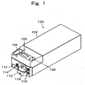
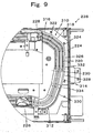
- a coin receiving and disbursing apparatus 100 has a coin receiving port 104 on an upper face on the front side of a body cover 102 of a vertically long box shape.
- the coin receiving port 104 is a vertically long D-shaped slot when viewed two-dimensionally, and has a width slightly larger than the diameter of the largest coin, and a length of about three times the largest coin. Beside the coin receiving port 104, a display 106 for displaying settings and alarm information, and an operational button 108 are disposed. The operational button 108 permits the settings to be changed by an operation thereof while checking the setting information displayed in the display 106.
- a bowl-like money discharging port 110 is provided in a lower part of the front face of the coin receiving and disbursing apparatus 100. Therefore, the money receiving port 104 and the money discharging port 110 are disposed almost in parallel.
- a full coin cash box 112 is disposed on the left side of the money discharging port 100. The cash box 112 may be removed after pulled out by unlocking a lock key 114 provided on the front face and they removed.
- a power key 116 is provided on the right side of the money discharging port 119.
- the power key 116 in an ON state comes into an OFF state when it is turned in a predetermined direction and the power key 116 in an OFF state comes into an ON state when it is turned oppositely.
- a setting key 118 is provided above the power key 116.
- the setting key 118 enables switching of a mode of the coin receiving and disbursing apparatus 100 by the position selected by a turning operation.
- the setting key 118 sets the coin receiving and disbursing apparatus 100 at a normal money receiving mode at a predetermined position, and sets it at a maintenance mode at another predetermined position.
- the maintenance mode by conducting a certain operation through operation of the operational button 108, it is possible to withdraw all the reserved coins, for example.
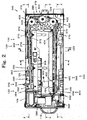
- a boxy slide frame 122 is disposed so as to be removable via a slide rail (not shown).
- devices are disposed in generally an upper half part and a lower half part.
- a received money conveying device 124 is disposed, and in a lower half part, a coin reserving device 126 and a disbursing money conveying device 128 are disposed.
- the received money conveying device 124 conveys a coin sent from an alignment device 130 at a certain speed along the received money conveying path 132.
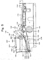
- the alignment device 130 aligns a plurality of or plural denominations of coins received in bulk from the money receiving port 104 into a line of coins. Accordingly, other device having a similar function may be used as well. As shown in Fig. 5 , in the present embodiment, the alignment device 130 is composed of a band conveyer 134 and breaking means 136 directly below the money receiving port 104.
- the band conveyer 134 is a conveyance belt 144 which is slightly wider than the coin having the largest diameter, and wound around a first roller 140 and a second roller 142 disposed parallel at a certain interval so that it forms an ascending slope with respect to a traveling direction of coins.
- the conveyance belt 144 receives a certain tension by a tension roller 146 disposed under an upper belt 144U. Between the tension roller 146 and the second roller 142, an upper belt relay part 148 is disposed substantially horizontally.
- the upper belt 144U between the first roller 140 and the tension roller 146 is inclined upward with respect to the traveling direction of coins.
- the second roller 142 is rotated in a clockwise direction in Fig. 5 by a driving motor 150, and the upper belt 144U moves from left below to the right above in Fig. 5 .
- a stationary guide axis 152 is provided on an upstream side of the traveling direction of coins so as to transverse below the upper belt 144U.
- the guide axis 152 is covered with a sleeve (not shown), and in rolling contact with the conveyance belt 144.
- a plate-like guide plate 154 On upstream side of the guide axis 152, a plate-like guide plate 154 is disposed and a slot-in sensor 156 for detecting a coin is attached.
- a belt which is covered with rubber having a large coefficient of friction with a coin, at least on its surface is preferred.
- the breaking means 136 breaks the piled up coins and aligns them one by one on the conveyance belt 144.
- the breaking means 136 is implemented by a breaking roller 158.
- the breaking roller 158 is placed directly above the belt 144 and is attached via a one-way clutch 162 to an axis 160 that is rotatably mounted in an opening on the lateral wall of the money receiving port 104.
- the axis 160 is drivingly connected with the driving motor 150, and rotates in the same direction as the second roller 142. In other words, the axis 160 is rotated in the clockwise direction in Fig. 5 at a predetermined speed ratio with respect to the upper belt 144U. In other words, the breaking roller 158 is rotated at a predetermined speed in the clockwise direction in Fig. 5 .
- the peripheral surface contacting with the upper belt 144U of the breaking roller 158 moves in a direction opposite to the traveling direction of the upper belt 144U.
- the axis 160 rotates in the same direction, however, the breaking roller 158 is not rotated because the rotating power is blocked by the one-way clutch 162.
- a coin passage gap 164 is formed which is slightly larger than the thickness of the thickest coin.
- the upper belt 144U is inhibited from moving downward, or moving in the direction leaving from the breaking roller 158 by the stationary guide axis 152. Consequently, in the case where thicknesses of coins other than the thickest coin are equal to or more than one half of the thickness of the thickest coin as is the case of euro coins, only one coin whose one face contacts the upper belt 144U is allowed to pass through the coin passage gap 164.
- standing coin detection sensors 166A, 166B and 166C are provided near the upper belt 144U of the money receiving port 104 and the first roller 140.
- the standing coin detection sensors 166A, 166B and 166C are disposed above the part which is in the lowest level of the inclining belt 144.
- the standing coin detection sensors 166A, 166B and 166C are transmissive photoelectronic sensors and provided in such a manner that a light projecting part is disposed on one side of the wall surface of the belt 144 and light receiving parts are disposed on the opposite side of the wall surface across the belt 106 and near the upper belt 144 in three different positions along the traveling direction of the belt 144.
- the standing coin detection sensors are provided in plural so as to securely detect any standing coin. However, if detection can be secured with only one sensor, the standing coin detection sensor may be only one.
- the slot-in sensor 156 which is usually disposed under the upper belt 144U, and the driving motor 150 is rotated.
- the upper belt 144U moves toward a denomination judging device 125 as will be described below, and the lower side of the periphery of the breaking roller 158 moves in an opposite direction. Accordingly, the coins pass one by one through the gap 164 as described above, and the coins are aligned in line on the upper belt 144 at least in the relay part 148.
- the driving motor 150 is forwardly rotated following a short-time reverse rotation. This reverse rotation allows the upper belt 144U to move in a reverse direction of the conveyance direction of coins.
- the upper belt 144U travels in the coin conveyance direction and the standing coin is moved together with the upper belt 144U at its lower end, and forced to fall on the upper belt 144U and passed through the gap 164.
- the received money conveying path 132 is composed of a judging and rejecting path 170 and a sorting conveyance path 172. First, explanation will be made on the judging and rejecting path 170.
- the judging and rejecting path 170 is disposed subsequently to the alignment device 130, and extends in the traveling direction of the band conveyer 134 so as to be substantially flush with the relay part 148 of the band conveyer 134 and placed on the upper face of a plate-like slide base 173.
- the first guide rail 174 is formed with a deviation guide part 176 inclining toward the center and the conveyance direction of coins D from one side of the band conveyer 134, and a judgment guide part 178 and a rejection guide part 180 continuing therefrom.
- the judgment guide part 178 and the rejection guide part 180 are linearly formed in series, and slope at a small angle from the traveling direction of coins D.
- the coin moving in such a manner as being dragged by the received money conveying device 124 is guided while the periphery thereof constantly being in close contact with the guide parts due to the inclination as described above. Therefore, the judging and rejecting path 170 is a linear path formed along the deviation guide part 176, the judgment guide part 178 and the rejection guide part 180.
- the denomination judging device 125 is disposed so as to face with the judgment guide part 178.
- the denomination judging device 125 determines whether a coin guided by the judgment guide part 178 is real or fake and determines the denomination thereof.
- real/fake and denomination are determined by detecting a diameter, a material and a thickness of a coin by a plurality of coils and comparing the detection results with reference values.
- a plate-like sensor attachment 182 is disposed parallel with the slide base 173 at a distance slightly larger than the thickness of the thickest coin above the slide base 173.
- first upper sensor 188U implementing a first diameter sensor 186 in which a coil (not shown) is wound on a first core 184U having a rectangular end face
- third upper sensor 194U implementing a third diameter sensor 190 in which a coil is wound on a third core 192U having a rectangular end face
- second upper sensor 200U implementing a third diameter sensor 196 having a second core 198U having a circular end face.
- first core 184U, the second core 198U and the third core 192U, a first core 184L of a first lower sensor 188L, a second core (not shown) of a second lower sensor 200L and a third core 192L of a third lower sensor 194L are disposed on the bottom face of the slide base 173.
- the second sensors 200U and 200L have good efficiency of magnetic flux because almost the whole periphery of the coil is surrounded by a circular partition.
- the slide base 173 and the sensor attachment 182 are made of a non-magnetic material, specifically, a resin so as not to attenuate the magnetic flux.
- the first diameter sensor 186 is constituted by differentially connecting the coils of the first upper sensor 188U and the first lower sensor 188L.
- the second diameter sensor 196 is constituted by cumulatively connecting the coils of the second upper sensor 200U and the second lower sensor 200L.
- the third diameter sensor 190 is constituted by cumulatively connecting the coils of the third upper sensor 194U and the third lower sensor 194L.
- the first diameter sensor 186 and the third diameter sensor 190 are disposed on a straight line X which is perpendicular to the judgment guide part 178, at a predetermined distance from the judgment guide part 178. More specifically, the first diameter sensor 186 is disposed in such a manner that when a one-cent coin having the smallest diameter moves while guided by the judgment guide part 178 (see the circle S shown by dotted line), the end portion faces about one third of the first cores 184L and 184R.
- the second diameter sensor 196 is disposed on the downstream of the coin traveling direction such that ends which are closer to the judgment guide part 178, of the core 198U of the second upper sensor 200U and the core (not shown) of the second lower sensor 200L slightly overlap with the cores 184U and 184L of the first diameter sensor 186, and the ends which are far from the judgment guide part 178 slightly overlap with the cores 192U and 192L of the third diameter sensor 190.
- the third diameter sensor 190 is disposed in such a manner that when a two-euro coin having the largest diameter moves under guidance (see the circle L shown by dotted line), the end portion faces about one third of the third cores 192U and 192L.
- the area of each core may be reduced since the core opposite to a coin is divided, and hence the sensitivity is improved.
- the accuracy of diameter determination improves and an advantage of low cost is also obtained by the coil-based sensor.
- the denomination judging device 125 may discriminate real/fake and determine the denomination by a device having a similar functionality, for example, by image recognition of a pattern on the surface of the coin followed by comparison with a reference image.
- the first diameter sensor 186 serves also as a thickness sensor because almost the entire face of the cores 184U and 184L thereof faces with a coin other than a one-cent coin.
- a material sensor 202 for determining a material of a coin is attached on a bottom end of the slide base 173 and near the judgment guide part 178.
- the material sensor 202 is structured by winding a coil around a core. Since the core of the material sensor 202 lies near the judgment guide part 178, it faces the entire surface of the coin.
- the reject coin sorter 129 is disposed downstream the denomination judging device 125.
- the reject coin sorter 129 sorts returning coins other than acceptable coins, as well as fake coins to the money discharging port according to the determination results by the denomination judging device 125.
- the reject coin sorter 129 includes a dropping port 206 formed on the slide base 173 and a reject member 208 disposed below the first guide rail 174 of the dropping port 206.
- the dropping port 206 is so designed that the length along the traveling direction of coins is larger than the diameter of the coin having the largest diameter, and the length in the direction perpendicular to the reject guide part 198 of the dropping port 206 is slightly smaller than the diameter of the coin having the smallest diameter.
- the length in the traveling direction of coins is increased, preferably, to twice or more of the diameter of the coin having the largest diameter.
- a drop assisting device for coins.
- the drop assisting device is, for example, a pusher that pushes a coin into the dropping port 206.
- the reject member 208 is movable between a guiding position G at which the upper face thereof slightly projects from the reject guide part 180 toward the received money conveying path 132, and a reject position R at which the upper face thereof recedes under the first guide rail 174 from the reject guide part 180 at the dropping port 206 in a plane which is flush with the slide base 173.
- the reject member 208 is moved between the guiding position C and the reject position R by a plunger 212 of a two-position solenoid 210 fixed to the slide frame 122. That is, whenever the solenoid 210 is excited, the reject member 208 is alternately switched between the guiding position G and the reject position R.
- a coin moving on the dropping port 206 while guided by the reject guide part 180 of the first guide rail 174 drops through the dropping port 206, slides down on the bottom surface of the reject path 214, guided to the disbursing money conveying device 128 and returned to the money discharging port 110 because the lower face of the edge on the side of the reject guide part 180 of the coin is not guided.
- the reject path 214 inclines such that a coin slides down by its own weight toward the disbursing money conveying device 128 from below the dropping port 206.
- the sorting conveyance path 172 sorts coins such that a predetermined denomination is sorted in a predetermined point during conveyance by the received money conveying device 124.
- the sorting conveyance path 172 is formed into a substantially U-shape from a slide base 220, e.g. stainless plate, arranged substantially horizontally, a second guide rail 222, a U-turn guide rail 224 and a third guide rail 226 fixed on the top face of the slide base 220, a first support rail 228 disposed parallel with the second guide rail 222 at a certain distance therefrom, a U-turn support rail 230 disposed at a certain distance from the U-turn guide rail 224 and a second support rail 232 disposed parallel with the third guide rail 226 at a certain distance therefrom.
- a slide base 220 e.g. stainless plate
- Each rail is formed from a plate slightly thicker than the coin having the largest thickness. Therefore, the sorting conveyance path 172 has a cross section of a shallow channel, and has a width which is slightly larger than the diameter of the coin having the largest diameter, and a thickness slightly larger than that of the coin having the largest thickness.
- the top face of the slide base 220 is formed with a plurality of protruding strips 234 extending in the longitudinal direction of the sorting conveyance path 172. This contributes reduction of friction when coins are conveyed by the received money conveying device 124 as will be described later.
- the top face may be formed flat, for example, by bonding a low-friction sheet rather than providing the protruding strips as described above.
- the received money conveying path 132 is formed into a U-shape from a path 236 leaving the money receiving port 104 which is opposite to the second guide rail 222, disposed downstream the judging and rejecting path 170, a U-turn path 238 opposite to the guide rail 224 and a path 240 approaching the money discharging port 110 along the third guide rail 226.
- the second guide rail 222 constituting the leaving path 236 is positioned on an extended line of the first guide rail 174.
- the second guide part 242 lies on an extended line of the reject guide part 180, and the second guide part 242 inclines at a slight acute angle with respect to the traveling direction D of coins.
- the leaving path 236 is provided with a first coin sorting part 244.
- the first sorting part 244 includes three denomination sorting parts, concretely, a one-cent sorting part 246, a two-cent sorting part 248 and a 10-cent sorting part 250. These sorting parts sort the coins conveyed along the second guide rail 222 by denomination.
- the sorting parts are respectively a one-cent sorting hole 252, a two-cent sorting hole 254 and a 10-cent sorting hole 256 which are substantially rectangular.
- a one-cent guiding edge 258 near the second guide rail 222 of the one-cent sorting hole 252 lies in a position slightly closer to the leaving path 236 than the second guide rail 222, while a one-cent dropping edge 260 far from the same is slightly farther from the second guide rail 222 than the diameter of the a one-cent coin, and formed parallel with the second guide rail 222.
- a one-cent coin will drop into the one-cent sorting hole 252 because the lower face of the periphery is not guided by the one-cent dropping edge 260.
- Coins having a diameter larger than the diameter of one-cent coin will pass through the one-cent sorting hole 252. This is because the lower face thereof is supported by the guiding edge 258 and the dropping edge 260.
- a two-cent guiding edge 262 near the second guide rail 222 of the two-cent sorting hole 254 lies in a position slightly closer to the leaving path 236 than the second guide rail 222, while a two-cent dropping edge 264 far from the same is slightly farther from the second guide rail 222 than the diameter of the a two-cent coin, and formed parallel with the second guide rail 222.
- a two-cent coin will drop into the two-cent sorting hole 254 because the lower face of the periphery is not guided by the two-cent dropping edge 264.
- Coins having a diameter larger than the diameter of two-cent coin will pass through the two-cent sorting hole 254. This is because the lower face thereof is supported by the guiding edge 262 and the dropping edge 264.
- a 10-cent guiding edge 266 near the second guide rail 222 of the 10-cent sorting hole 256 lies in a position slightly closer to the leaving path 236 than the second guide rail 222, while a 10-cent dropping edge 268 far from the same is slightly farther from the second guide rail 222 than the diameter of the a 10-cent coin, and formed parallel with the second guide rail 222.
- a 10-cent coin will drop into the 10-cent sorting hole 256 because the lower face of the periphery is not guided by the 10-cent dropping edge 268.
- Coins having a diameter larger than the diameter of 10-cent coin will pass through the 10-cent sorting hole 256. This is because the lower face thereof is supported by the guiding edge 266 and the dropping edge 268.
- a corner on the downstream side of a dropping line 268 of the 10-cent sorting hole 256 is formed into an arc having almost the same curvature of the outer periphery of a 10-cent coin. This prevents coins other than 10-cent coins from dropping into the 10-cent sorting hole 256.
- the second sorting part 270 is provided along the third guide rail 226.
- the second sorting part 270 includes five denomination sorting parts, concretely, a five-cent sorting part 272, a 20-cent sorting part 274, a one-euro sorting part 276, a 50-cent sorting part 278 and a two-euro sorting part 280.
- sorting parts sort the coins conveyed along the third guide rail 226 by denomination.
- the sorting parts are respectively a five-cent sorting hole 282, a 20-cent sorting hole 284, a one-euro sorting hole 286, a 50-cent sorting hole 288 and two-euro sorting hole 290 which are substantially rectangular.
- a five-cent guiding edge 292 near the third guide rail 226 of the five-cent sorting hole 282 lies in a position slightly closer to the approaching path 240 than the third guide rail 226, while a five-cent dropping edge 294 far from the same is slightly farther from the third guide rail 226 than the diameter of the a five-cent coin, and formed parallel with the third guide rail 226.
- a five-cent coin will drop into the five-cent sorting hole 282 because the lower face of the periphery is not guided by the five-cent dropping edge 294.
- Coins having a diameter larger than the diameter of five-cent coin will pass through the five-cent sorting hole 282.
- a corner on the upstream side of a dropping line 294 of the 5-cent sorting hole 282 is formed into an arc having almost the same curvature of the outer periphery of a 5-cent coin. This prevents coins other than 5-cent coins from dropping into the 5-cent sorting hole 282.
- a 20-cent guiding edge 296 near the third guide rail 226 of the 20-cent sorting hole 284 lies in a position slightly closer to the approaching path 240 than the third guide rail 226, while a 20-cent dropping edge 298 far from the same is slightly farther from the third guide rail 226 than the diameter of the a 20-cent coin, and formed parallel with the third guide rail 226.
- a 20-cent coin will drop into the 20-cent sorting hole 284 because the lower face of the periphery is not guided by the 20-cent dropping edge 298.
- Coins having a diameter larger than the diameter of 20-cent coin will pass through the 20-cent sorting hole 284. This is because the lower face thereof is supported by the guiding edge 296 and the dropping edge 298.
- one-euro coin will drop into the one-euro sorting hole 286 because the lower face of the periphery is not guided by the one-euro dropping edge 302.
- Coins having a diameter larger than the diameter of one-euro coin will pass through the one-euro sorting hole 286. This is because the lower face thereof is supported by the guiding edge 300 and the dropping edge 302.
- a 50-cent guiding edge 304 near the third guide rail 226 of the 50-cent sorting hole 288 lies in a position slightly closer to the approaching path 240 than the third guide rail 226, while a 50-cent dropping edge 306 far from the same is slightly farther from the third guide rail 226 than the diameter of the a 50-cent coin, and formed parallel with the third guide frame 226.
- 50-cent coin will drop into the 50-cent sorting hole 288 because the lower face of the periphery is not guided by the 50-cent dropping edge 306.
- Coins having a diameter larger than the diameter of 50-cent coin will pass through the 50-cent sorting hole 288. This is because the lower face thereof is supported by the guiding edge 304 and the dropping edge 306.
- the two-euro sorting hole 290 is not formed on the slide base 220, but formed by the third guide rail 226 and the second support rail 232. In other words, all coins that have not dropped into the previous sorting holes will drop into the two-euro sorting hole 290.
- the length of each sorting hole along the traveling direction of coins should be at least 1.5 times, preferably two times or more of the diameter of the coin of target denomination, in order to make a coin securely drop even when the conveyance speed of coin is raised.
- the sorting holes of the present embodiment are arranged in order of increasing diameter among euro coins.
- the sorting part has a function of sorting a coin of particular denomination conveyed on the sorting conveyance path 172 in a particular position. Therefore, the sorting part may be replaced by other device having a similar function. For example, a coin of a certain denomination may be forcedly deviated from the sorting conveyance path.
- the U-turn path 238 guides a coin having passed through the leaving path 236 into the approaching path 240, namely, guides a coin having passed through the first sorting part 244 into a second sorting part 270.
- the U-turn path 238 composed of the slide base 220, the U-turn guide rail 224 and the U-turn support rail 230 has a channel-like cross section, and is a U-shape groove when viewed two-dimensionally, and the groove has a depth and a width which are similar to those of the sorting conveyance path 172.
- the U-turn path 238 is so designed that an inlet part 310 on the side of the leaving path 236 is a relatively large arc, an outlet part 12 near the approaching path 240 is an arc having smaller curvature than that of the inlet part 310, and an intermediate part 314 therebetween is an arc having a larger curvature than the inlet part 310.
- the inlet part 310 is composed of a first linear segment 316 forming a blunt angle with the first support rail 228, a second linear segment 318 forming a blunt angle with first linear segment 316, and a third linear segment 326 forming a blunt angle with the second linear segment 318, and these linear segments are smoothly connected by a first arcuate segment 322 and a second arcuate segment 324. Construction of the arcuate inlet part 310 by combination of the linear segments and arcuate segments allows the coins conveyed by the received money conveying device 124 as will be described below to be conveyed at a certain interval.
- the intermediate part 314 is composed of a fourth linear segment 328 forming a blunt angle with the third linear segment 326, a fifth linear segment 330 forming a blunt angle with the fourth linear segment 328, a third arcuate segment 332 connecting the third linear segment 326 and the fourth linear segment 328, and a fourth arcuate segment 334 connecting between the fourth linear segment 328 and the fifth linear segment 330.
- the U-turn path 238 may be replaced by other structure having a similar function.
- construction from the slide base 220, the U-turn guide rail 224 and the U-turn support rail 230 is advantageous because it may be constructed at low cost.
- the received money conveying device 124 conveys a coin sent from the alignment device 130 along the received money conveying path 132.
- it conveys a coin sent from the alignment device 130 along the judging and rejecting path 170, the leaving path 236, the U-turn path 238 and the approaching path 240, under the guidance by the first guide rail 174, the second guide rail 222, the U-turn guide rail 224 and the third guide rail 226 at a predetermined speed.
- the received money conveying device 124 includes a first conveying unit 342, a second conveying unit 344, a third conveying unit 346 and fourth conveying unit 348.
- the first conveying unit 342 is provided so as to face with the relay part 148 of the band conveyer 144 to the judgment guide part 178.
- the second conveying unit 344 is provided so as to face with the reject guide part 180, the one-cent sorting part 246 and the two-cent sorting part 248.
- the third conveying unit 346 is provided so as to face with the 10-cent sorting part 250 and the U-turn guide rail 224.
- the fourth conveying unit 348 is provided so as to face with the five-cent sorting part 272, the 20-cent sorting part 274, the one-euro sorting part 276, the 50-cent sorting part 278 and the two-euro sorting part 280.
- these conveying units are formed of a pulley and a belt, and conveys a coin by friction power between the belt and the coin.
- first conveying unit 342 the details of the first conveying unit 342 will be explained with reference to Fig. 2 .
- the first conveying unit 342 includes a first pulley 354, a second pulley 358, and a first endless belt 340 wound around these pulleys.
- the first pulley 354 is rotatably attached to a first stationary axis 352 which extends perpendicular to a traveling direction of the belt 144 so as to be substantially parallel with a conveyer frame 350 above the relay part 148.
- the second pulley 358 is rotatably attached to a second stationary axis 356 which extends perpendicular to the longitudinal direction of the judging and rejecting conveyance path 170, so as to be substantially parallel with the slide base 173 between the denomination judging device125 and the reject part 126 above the slide base 173.
- the gap between the bottom face of the first belt 340 and the top face of the relay part 148 and the top face of the slide base 173 is smaller than the thickness of the thickest coin.
- the bottom face of the first belt 340 tilts forward so as to be closer to the top face of the slide base 173 as it comes closer to the reject coin sorter 129 and slightly tilts so as to be closer to the judgment guide part 178 and the reject guide part 180.
- a lower part of the first belt 340 is positioned between the first guide rail 174 and the sensor attachment 182, and the bottom face of the belt comes into contact with a top face of a coin, whereby the coin is moved by friction contact with the coin.
- the first belt 340 shifts a coin while contacting at the center in the case of a coin S having the smallest diameter, or contacting at a portion closer to the first guide rail 174 rather than the center in the case of a coin L having the largest diameter.
- the first diameter sensor 186, the second diameter sensor 196 and the third diameter sensor 190 make it possible to accurately detect diameters of various sizes of coins that are conveyed in mixture.
- the lower belt of the first belt 340 is pushed against the slide base 173 by means of a pushing device 360.
- a press roller 362 is applied on the first belt 340 from above.
- the press roller 362 is rotatably attached in a lower end part of a lever 366 which is rotatably attached to the axis 364 projecting in the lateral direction from the conveyance frame 350.
- the lever 366 is latched by a stopper (not shown), and a lower end of the first belt 340 has a certain interval with the slide base 173.
- the lever 366 is urged so as to be rotatable in the counter clockwise direction by a string-wound spring. Therefore, the first belt 340 between the first pulley 354 and the second pulley 358 is pushed against the slide base 173 with certain power. In other words, a coin is pushed against the slide base 173 with certain power by the first belt 340.
- the second conveying unit 344 includes a third pulley 368 formed integrally with the second pulley 358 and provided in a position farther from the first guide rail 174 than the second pulley 358, a fourth pulley 372 rotatably attached to a third stationary axis 370 extending perpendicular to the leaving path 236 and disposed between the two-cent sorting part 248 and the 10-cent sorting part 250, and a second endless belt 374 wound around the third pulley 368 and the fourth pulley 372.
- the gap between the bottom face of the second belt 374 and the top face of the slide base 173 and the top face of the slide base 220 of the leaving path 236 is smaller than the thickness of the thinnest coin.
- the bottom face of the second belt 347 tilts forward so as to be closer to the top face of the slide bases 173 and 220 as it comes closer to the 10-cent sorting part 250 and slightly tilts so as to be closer to the second guide rail 222.
- the pushing device 360 as described above is provided also for a lower belt of the second belt 374.
- the pushing device 360 is provided in plural at a predetermined interval, such as an interval similar to that of coins resulting from difference in speed between the band conveyer 134 and the first conveying unit 342. That is, when coins are continuously sent, the interval of coins is kept by pushing such coins almost simultaneously with the pushing devices 360.
- the third conveying unit 346 includes a fifth pulley 373 formed integrally with the fourth pulley 372 and provided in a position farther from the second guide rail 222 than the fourth pulley 372, a sixth pulley 376 rotatably attached to a fourth stationary axis 375 extending perpendicular to the approaching path 240 directly before the approaching path 240 or above the outlet part 312 and disposed directly before the five-cent sorting part 272, a curve part guiding device 378 for conveying a coin along the U-turn path 238, and a third endless belt 380 wound around the fifth pulley 373 and the sixth pulley 376 and guided by the guided by the curve part guiding device 378.
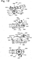
- the curve part guiding device 378 includes a first guide roller 381, a second guide roller 382, a third guide roller 384, a fourth guide roller 386 and a fifth guide roller 388 closely provided above the slide base 220. All of these first guide roller 381 to fifth guide roller 388 are formed in the same manner, and explanation will be made on the third guide roller 384 shown in Fig. 12 , representatively.
- the third guide roller 384 is provided so that a guide groove 390 for the third belt 380 is formed to have a J-shaped cross section, and the lower end of the third belt 380 is positioned closer to the slide base 220 than the bottom face of the third guide roller 384.
- the third guide roller 384 is rotatably supported by a vertical axis 398 fixed to a support lever 396 pivotably supported by a stationary axis 394 attached horizontally to a stay 392 fixed to the conveyance frame 350.
- the support lever 396 is urged in the clockwise direction by a spring 400 provided between the conveyance frame 350 and the lever, and is so configured that the support lever 396 is stopped at a stopper part 402 of the conveyance frame 350 and the bottom face of the third belt 380 keeps a predetermined interval with the top face of the slide base 220 which is smaller than the thickness of the thinnest coin.
- a screw bar 404 is rotatably attached to an end of the support lever 396 while inhibited from sliding in the axial direction.
- This screw bar 404 is screwed into a screw hole 406 of the conveyance frame 350 and axially fixed by a lock nut 408.
- the spring 400 is provided outside the screw bar 404.
- the support lever 396 is attached with a third guide roller automatic positioning unit 410.
- the guide roller automatic positioning unit 410 automatically adjusts the distance of the third guide roller 384 from the slide base 220 in correspondence with the thickness of the coin, and moves the coin along the U-turn path 238 at a predetermined speed.
- a first stay 412 is attached so as to be rotatable about the vertical axis, and fixed by a screw 416 penetrating through a arcuate slot 414.
- the first stay 412 has a vertical portion 418 hanging down in a position deviated from the support lever 396, and is attached with a roller stay 424 so as to allow positioning in the up-and-down direction.
- a feeler roller 420 is rotatably attached by an axis 422.
- a lower end of the feeler roller 420 is designed to come into contact with an upper part of the third belt 380 on the upstream side of the third roller 384 which is not in contact with a coin.
- the feeler roller 420 is adjusted by a range of the arcuate slot 414 so that its rotational axis is perpendicular to the third belt 380 when viewed two-dimensionally.
- the first guide roller 381 is disposed so as to face with the first arcuate segment 322
- the second guide roller 382 is disposed so as to face with the second arcuate segment 324
- the third guide roller 384 is disposed so as to face with the third arcuate segment 332
- the fourth guide roller 386 is disposed so as to face with the fourth arcuate segment 334
- the fifth guide roller 388 is disposed so as to face with the outlet part 312.
- the third belt 380 is linear between each guide roller, and such linear segments face with the first linear segment 316, the second linear segment 318, the third linear segment 326, the fourth linear segment 328 and the fifth linear segment 330. Then these linear segments of the third belt 380 slightly incline so as to come closer to each linear segment of the U-turn guide rail 224 as they proceed in the downstream direction.
- a coin conveyed along the U-turn path 238 is conveyed while being guided by the U-turn guide rail 224.
- the upper part of the third belt 380 is guided by pulleys 428, 430, 432 rotatably attached to stationary axes 422, 424, 426 fixed to the conveyance frame 350.
- the third belt 380 circulates while being guided by the fifth pulley 373, the first guide roller 381, the second guide roller 382, the third guide roller 384, the fourth guide roller 386, the fifth guide roller 388, the sixth pulley 376, and the guide pulleys 432, 430, 428.
- the fourth conveying unit 348 includes a seventh pulley 434 formed integrally with the sixth pulley 376 and provided in a position farther from the third guide rail 226 than the sixth pulley 376, an eighth pulley 438 rotatably attached to a driving axis 436 extending perpendicular to the approaching path 240 and disposed downstream the two-cent sorting part 280, and a fourth endless belt 440 wound around the seventh pulley 434 and the eighth pulley 438.
- the gap between the bottom face of the fourth belt 440 and the top face of the slide base 220 of the approaching path 240 is smaller than the thickness of the thinnest coin.
- the bottom face of the fourth belt 440 tilts to approach the third guide rail 226.
- the fourth belt 440 is disposed so as to face with the five-cent sorting part 272, the 20-cent sorting part 274, the one-cent sorting part 276, the 50-cent sorting part 278 and the two-euro sorting part 280. Likewise the above, the fourth belt 440 pushes a coin against the slide base 220 with predetermined power by means of the pushing device 360.
- the second pulley 358, the third pulley 360, the fourth pulley 372, the fifth pulley 373, the sixth pulley 376 and the seventh pulley 434 have the same diameter. This makes it possible to use the same specification of pulleys for these pulleys, which is advantageous in terms of cost.
- These belts may be a round belt, a V belt or a flat belt made from polyurethane rubber.
- a driving device 450 of the received money conveying device 124 will be explained with reference to Fig. 2 .
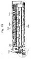
- an electric motor 452 is fixed, and a driving gear 460 fixed on an output axis (not shown) of a reducer 454 meshes with a driven gear 462 formed integrally with the eighth pulley 438. Therefore, as the electric motor 452 rotates, the eighth pulley 438 rotates in the clockwise direction in Fig. 13 , and the fourth belt 440 is circulated in the clockwise direction.
- the sixth pulley 376 is rotated integrally with the seventh pulley 434, and the third belt 380 is circulated in the same direction. Further, since the fourth pulley 372 is rotated integrally with the fifth pulley 373 by the third belt 380, the second belt 374 is circulated in the same direction. Furthermore, since the second pulley 358 is rotated integrally with the third pulley 360, the first belt 340 is circulated in the same direction.
- the third conveying unit 346 is driven by friction transmitted from the fourth conveying unit 348
- the second conveying unit 344 is driven by friction transmitted from the third conveying unit 346
- the conveying unit 342 is driven by friction transmitted from the second conveying unit 344. Since each conveying unit has a respective friction resistance, the conveyance speed of the fourth conveying unit 348 is largest, and the he conveyance speed decreases in the order of the third conveying unit 346, the second conveying unit and the first conveying unit 342.
- the conveying speed of coin decreases in the order of at higher speed in the order of the fourth conveying unit 348, the third conveying unit 346, the second conveying unit 344, and the first conveying unit 342.
- the interval of successively conveyed coins becomes sequentially larger.
- a jam resulted from a following coin catching up with a foregoing coin will not occur.
- the coin reserving device 126 reserves coins having sorted by the denomination-based sorting parts by denomination. More specifically, a coin reserving and flicking device 470 is provided for each denomination.
- the coin reserving and flicking device 470 reserves coins in bulk, and flicks out the reserved coins one by one. Therefore, the coin reserving and flicking device 470 may be replaced by other device having a similar function.
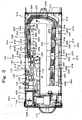
- the coin reserving and flicking device 470 is implemented by a coin hopper 472.
- the coin hopper 472 includes a base 474 provided diagonally, a rotary disc 476, a reserving bowl 478, a flicking unit 480, a coin sensor 482, a driving motor 484 and a frame 486.
- the base 474 has a boxy form in which a decelerating mechanism 488 and the like are disposed.
- the base 474 is fixed in a slope part of the frame 486 which is right triangle when viewed laterally and inclined at about 45 degrees.
- the minimum inclination angle is about 30 degrees because the degree of influence of the diameter of the rotary disc 476 on the size of the coin hopper 472 increases, and the maximum inclination angle is about 60 degrees because the flicking efficiency of coin is deteriorated if the inclination angle is too large.
- the hopper bowl 478 of a cylindrical shape is detachably fixed on the top face of the base 474.
- the lower part of the hopper bowl 478 is formed with a circular hole 490 and an upper opening 492 is rectangular in order to increase the coin reserving capacity.
- the rotary disc 476 has a plurality of through holes 491 provided at a predetermined interval, an angle stirrer 494 in the center of the top face, and a coin pushing part 496 in the bottom face.
- the coin dropping through the through hole 491 is held by the upper face 498 of the base 474, and in a normal state, rotated in the counter clockwise direction together with the rotary disc 476 by the pushing part 496 of the rotary disc 476 normally rotating in the counter clockwise direction in Fig. 14 , while guided by the circular hole 40 at the periphery.
- the coin is prevented from moving by pins 500, 502 protruding in predetermined positions of the top face of the base 474, and pushed in the circumferential direction of the rotary disc 476.
- the flicking opening 504 is provided with a stationary guide roller 506 and the flicking unit 480.
- the flicking unit 480 has a roller 510 that is rotatably attached to an end of a lever 508 pivotably attached to a stationary axis 507, and the lever 508 is urged so as to approach the rotary disc 476 by a string-wound spring 512.
- the lever 508 is latched by a stopper 514 at the position where the roller 510 comes into close to the rotary disc 476, and held at a standby position.
- the gap between the stationary guide roller 506 and the roller 510 in their standby positions is smaller than the diameter of the coin being reserved. Since the coin pushed by the pushing part 496 is guided on its either side by the stationary guide roller 506, the roller 510 is moved in the clockwise direction in Fig. 14 . Then immediately after the diametrical part of the coin has passed between the stationary guide roller 506 and the roller 510, the lever 508 is quickly rotated in the counterclockwise direction by the spring 512, and the coin is flicked out.
- the coin dropper 516 allows a coin that rotates integrally with the rotary disc 476 while a surface part thereof is in close contact with the peripheral surface of the circular hole 490 and a circumferential edge of thereof rides on an edge of the rotary disc 476, to drop through the through hole 491.
- the coin dropper 516 is formed into a channel form from a metal plate, and has a slot 518 on each end.
- the coin dropper 516 is attached to a lateral wall of the hopper bowl 478 in such a manner that allows positional adjustment along the axial line of the circular hole 490 by a screw 520 penetrating through the slot 518.
- An intermediate part 522 of the coin dropper 516 extends along the axial line of the circular hole 490 at one end of the hopper bowl 478, and inserted through a slit 524 formed in proximity to the wall face of the circular hole.
- the intermediate part 522 lies directly above the edge of the rotary disc 476 in the circular hole 490.
- the distance between the inner face of the intermediate part 522 and the outer lateral line of the through hole 491 of the rotary disc 476 is set so as to be one half or less of the thickness of the coin being reserved. It is preferred that the inner face of the intermediate part 522 overlaps the periphery of the through hole 491 when the rotary disc 476 is viewed two-dimensionally.
- the rotary disc 476 is attached to the upper end of the rotational axis 525 which is rotatably fixed to the base 474 in such a manner that it is axially slidable but rotation relative to the rotational axis 525 is inhibited.
- the rotary disc 476 and the top face 498 of the base 474 with a sim having low coefficient of friction, it is possible to adjust the distance therebetween and positioning the rotary disc 476 depending on the thickness of the coin.
- the position adjusting device of the rotary disc 476 with respect to the thickness of the coin may be replaced by a device other than the sim described above having s a similar function. Also the position adjusting mechanism of the coin dropper 516 may be replaced by other device having a similar function.
- the coin sensor 482 is a sensor for detecting a coin that is flicked by the flicking unit 480, and may be implemented by a proximity sensor, an optical sensor and the like. However, it is preferred to use a proximity sensor because of its insusceptibility to dusts and unnecessity of maintenance.
- the coin hopper having the above structure is arranged in line along the path 236 below the first sorting part 244 of the leaving path 236 as shown in Fig. 4 , to constitute a first hopper array 560.
- the first hopper array 560 is made up of a one-cent hopper 562 disposed below the one-cent sorting part 246, a two-cent hopper 564 disposed below the two-cent sorting part 248 and a 10-cent hopper 566 disposed below the 10-cent hopper 250.
- an upper opening 492 of a hopper bowl 478 of the one-cent hopper 562 is disposed below the one-cent sorting hole 252
- an upper opening 492 of the two-cent hopper 564 is disposed below the one-cent sorting hole 254
- an upper opening 492 of the 10-cent hopper 566 is disposed below the 10-cent sorting hole 254.
- a second hopper array 568 is provided along the approaching path 240.
- the first hopper array 560, the disbursing money conveying device 128 and the second hopper array 568 are arranged in parallel.
- the second hopper array 568 is made up of a five-cent hopper 570 disposed below the five-cent sorting part 272, a 20-cent hopper 572 disposed below the 20-cent sorting part 274, a one-euro hopper 574 disposed below the one-euro sorting part 276, a 50-cent hopper 576 disposed below the 50-cent sorting part 278, and a two-euro hopper 578 disposed below the 2-euro sorting part.
- An upper opening 492 of a hopper bowl 478 of the five-cent hopper 570 is disposed below the five-cent sorting hole 282
- an upper opening 492 of the 20-cent hopper 572 is disposed below the 20-cent sorting hole 284
- an upper opening 492 of the one-euro hopper 274 is disposed below the one-euro sorting hole 286
- an upper opening 492 of the 50-cent hopper 576 is disposed below the 50-cent sorting hole 288, and an upper opening 492 of the two-euro hopper 578 is disposed below the two-euro sorting hole 290.
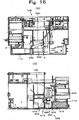
- the hoppers of the first hopper array 560 and the hoppers of the second hopper array 568 are symmetrically disposed at predetermined intervals while intervened by the disbursing money conveying device 128 as shown in Fig. 15 .
- the base 474 is symmetrically arranged as is an isosceles triangle, and coins are flicked out toward the opposing hopper arrays upwardly and diagonally.
- the momentum of the flicked out coin is attenuated by the gravity, and the coin drops into the disbursing money conveying device 128 after striking against the backside of the slide base 200.
- the coin hopper 472 of the first hopper array 560, and a part of the coin hopper 472 of the second hopper array 568 overlap with respect to the disbursing money conveying device 128 in the lateral direction.
- a part of the driving motor 484 and the disbursing money conveying device 128 overlap with each other. This is advantageous in that the width of the coin receiving and disbursing apparatus 100 may be reduced.
- the disbursing money conveying device 128 conveys coins flicked out from the coin hoppers 562, 564, 566, 570, 572, 574, 576 and 578, and coins rejected in the reject coin sorter 128 to the money discharging port 110.
- coins flicked out from the filled coin hopper are conveyed to the money discharging port 110 or a distributing unit 582 of the cash box 112 in order to store the coins in the cash box 112.
- the disbursing money conveying device 128 is a money discharging belt 584, and substantially horizontally disposed along the first hopper array 560 and the second hopper array 568. Further, as shown in Fig. 15 , the top face of the money discharging belt 584 on which coins are conveyed is provided at a position where it overlaps with the sideling rotary disc 476 in the up-and-down direction, at a level lower than the flicking unit 480.
- the disbursing money conveying device 128 is disposed between an upper end and a lower end of the rotary disc 476.
- the disbursing money conveying device 128 is driven by the electric motor 590 fixed to the frame 350 via a belt 592.
- the distributing unit 582 distributes coins conveyed by the disbursing money conveying device 128 into the money discharging port 110 or the cash box 112.
- a distributing plate 594 is fixed to an axis 596 existing below and beside the discharged money disbursing money conveying part 128.
- the distributing plate 594 is disposed right beside and below the conveyance belt 584, and in an upper part of an end part of the bowl-like money discharging port 110.
- This plate 594 is selectively shifted by a shifter 598 between a reserving position S below the belt 584 where the top face is inclined toward the cash box 112 and a money discharging position P standing on the lateral side of the disbursing money conveying device 128 shown by the dotted line.
- the plate 594 when the plate 594 is in the money discharging position P, the plate 594 is not located below the belt 584, and hence the coin conveyed by the disbursing money conveying device 128 directly drops into the bowl-like money discharging port 110.
- the plate 594 When the plate 594 is in the reserving position S, the coin dropped from the disbursing money conveying device 128 slides down the plate 594 after dropping on the plate 594, to be reserved in the cash box 112. Therefore, the distributing unit 582 may be replaced by other device having a similar function.
- a pin 604 fixed to a plunger 602 of a solenoid 600 fixed to the frame 122 is inserted through a slot (not shown) of the lever extending opposite to an axis 596 of the lever 606.
- the lever 606 is fixed to the axis 596, and fixed with a pin 612 at its end.
- the pin 612 is movable in the arcuate slot 614 extending about an axis 608, and movement thereof is restricted by the both ends of the slot. Therefore, the plunger 602 is usually urged by a spring 616 so as to protrude. As a result, the pin 612 is stopped at one end of the slot 614, and the lever 606 is held at the position shown by the dotted line, with the result that the plate 594 is held at the money discharging position P. When the solenoid 600 is excited, the pin 612 is stopped at another end of the slot 614, and the plate 594 is held at the reserving position S.
- a single coin slot-in unit 622 it is preferred to detachably attach a single coin slot-in unit 622 to an upper end opening 620 of the money receiving port 104.
- a restriction plate 626 formed with a slot-in plate through which only one coin may be inserted is pivotably attached to an axis 628 fixed to the back wall to which the breaking roller 158 is attached.
- a slot-in slit 624 is formed so as to extend laterally.
- the slot-in slit 624 is rectangular and has a diameter slightly larger than that of the two-euro coin having the largest diameter, and a thickness slightly larger than that of the 50-cent coin having the largest thickness.
- the slot-in slot 624 is formed such that the longitudinal direction thereof is perpendicular to the traveling direction of the band conveyer 134.
- a abutting plate 670 in a form of flat plate extending upward is provided.
- the coin is readily inserted through the slot-in slit 624, and the restriction plate 626 is easy to pivot about the axis 628 by clipping the plate 670.
- the restriction plate 626 may be detachably attached to the money receiving port 104 with a screw or the like, or may be formed integrally with the money receiving port 104. Further, the restriction plate 626 may be detachably attached to the money receiving port 104, or may allow selection between a single reception mode wherein coins are inserted through the slot-in slit 624 one by one and a collective reception mode wherein coins are collectively inserted through the money receiving port 104, as appropriate.
- the reference character "C" means a coin.
- the following embodiment the case when a single coin slot-in unit 622 is not mounted to the money receiving port 104 will be illustrated.
- a coin is inserted through the money receiving port 104, and placed on the belt 144 near the slot-in sensor 156, it is detected by the slot-in sensor 156.
- the driving motor 150 is forwardly rotated, and the upper belt 144U of the belt 144 is moved right in Fig. 5 .
- the breaking roller 158 is rotated in the clockwise direction. Then the electric motor 452 rotates, and the eighth pulley 438 is rotated via the driving gear 460, the driven gear 462 and the driving axis 436, and the fourth belt 440 is circulated in the clockwise direction in Fig. 13 .
- the third belt 380 is circulated in the same direction via the seventh pulley 434 and the sixth pulley 376.
- the second belt 374 is circulated in the clockwise direction in Fig. 10 via the fifth pulley 373 and the fourth pulley 372.
- the first belt 340 is circulated in the same direction via the third pulley 360 and the second pulley 358.
- the electric motor 590 rotates and drives so that the top face of the money discharging belt 584 of the disbursing money conveying device 128 moves left in Fig. 8 via the belt 592.
- the plunger 602 is pulled down by the spring 616, the pin 612 is stopped by the right end edge of the arcuate slot 614 in Fig. 16B , and the distributing plate 594 is held at the money discharging position P.
- a coin conveyed by the disbursing money conveying device 128 is in a condition of being fed to the money discharging port 110.
- Coins on the belt 144 are separated by the breaking roller 158 and aligned one by one while either face is in contact with the upper belt 144U, and passed through the gap 164 below the breaking roller 158. Then the bottom face of the first belt 340 and the top face of the coin come into contact with each other at the relay part 148, and after dragged in short time by the first belt 340 traveling slightly faster than the belt 144, the coin is transferred on the slide base 173.
- the coin on the slide base 173 is moved in the conveyance direction D by the first belt 344, and guided by the first guide rail 174 after contacting with the deviation guide part 176. After guided by the deviation guide part 176, the coin is guided by the judgment guide part 178. Since the first belt 340 inclines so as to form an acute angle with the judgment guide part 178and the reject guide part 180, the coin is conveyed with being in contact with the judgment guide part 178.
- the coin since the first belt 340 is provided so that it becomes closer to the first guide rail 174 as it goes downstream, the coin is conveyed while receiving pushing power by the first guide 174. Therefore, the coin moves along the judgment guide 178 in the denomination judging device 125.
- the denomination judging device 125 judges the material of the coin conveyed by the first belt 340 according to a signal from the material sensor 202 which is able to face with every size of coins, and judges the diameter of according to signals from the first diameter sensor 186, the second diameter sensor 196 and the third diameter sensor 190, and judges the thickness of the coin according to a signal from the first diameter sensor 186.
- a signal corresponding to the opposing area is outputted from the first diameter sensor 186, while no signal is transmitted from the second diameter sensor 196 and the third diameter sensor 190.
- the judgment is achieved by comprehensive judgment by comparing these signals with a reference value.
- the diameter and thickness are judged according to signals from the first diameter sensor 186, the second diameter sensor 196 and the third diameter sensor 190, and the denomination of each coin is identified. According to the identification result, the solenoid 210 is excited for a predetermined time in order to expel the fake or unacceptable coins. Upon excitation of the solenoid 210, the reject member 208 is moved below the first guide rail 174.
- the coin having passed through the denomination judgment device 125 is delivered to the second belt 374 from the first belt 340, and reaches the reject coin sorter 129. Since the second belt 374 is also inclined so as to cross with the reject guide part 180 and the second guide rail 222 at an acute angle, the coin is conveyed along the leaving path 236 while the periphery is pushed against the reject guide part 180 and the second guide rail 222.
- the coin When a fake or unacceptable coin passes the reject coin sorter 129, the coin will drop into the reject path 214 from the dropping port 206 of the reject guide part because the reject member 208 lacks the point at which the lower part of the periphery of the coin is supported. Then the coin slides on the inclined bottom face of the reject path 214 and drops on the money discharging belt 584. The dropped coin is conveyed toward the money discharging port 110 by the money discharging belt 584, and allowed to drop through the money discharging port 110 for return.
- the denomination judging device 125 identifies an acceptable coin from one-cent coin to two-euro coin
- the solenoid 210 is not excited. Accordingly, the reject member 208 is positioned on the center side of the judging and rejecting conveyance path 170 than the reject guide part 180. As a result, the coin passes through the reject coin sorter 129 while being supported at a lower side of the periphery by the reject member 208 and the slide base 173.
- the coin passed through the reject coin sorter 129 travels the leaving path 236 while the periphery thereof is guided by the second guide rail 222.
- the one-cent coin drops into the sorting hole 252.
- the dropped one-cent coin is reserved in a reservation bowl 478 of the one-cent hopper 562.
- Other denominations of coins having larger diameter than the one-cent coin will reach the two-cent sorting hole 254 provided downstream while supported by the edge 260 at its bottom face.
- a two-cent coin drops into the two-cent sorting hole 254 and then reserved in the two-cent hopper 564.
- the coin is delivered to the third belt 380.
- a 10-cent coin drops into the 10-cent sorting hole 256 and reserved in the 10-cent hopper 566.
- the coin that is not sorted in the first sorting part 244 is conveyed along the U-turn path 238 by friction contact with the third belt 380 while guided by the U-turn guide rail 224.
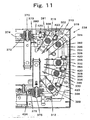
- the U-turn path 238 is arcuate, and as shown in Fig. 11 , the third belt 380 guided by the first guide roller 381 faces with the arcuate segment 322, the third belt 380 guided by the second guide roller 382 faces with the arcuate segment 324, the third belt 380 guided by the third guide roller 384 faces with the arcuate segment 332, the third belt 380 guided by the fourth guide roller 386 faces with the arcuate segment 334, the third belt 380 guided by the fifth guide roller 388 faces with the arcuate segment of the outlet part 312, and the belt 380 in a linear condition between each guide roller faces with each of the linear segments 316, 318, 326, 328 and 330.
- the detection roller 420 is pushed up by the third belt 380 that is pushed up by the 50-cent coin.
- the support lever 396 is pivoted about the stationary axis 394 via the roller stay 424 and the first stay 412, resulting that the guide roller 384 is moved upward and then the 50-cent coins reaches the third guide roller 384. In this manner, the thick 50-cent coin can smoothly pass without coming into collision with the guide roller 384.
- the coin is delivered to the fourth belt 440 from the third belt 380. Since the fourth belt 440 is inclined so as to cross with the third guide rail 226 at an acute angle, the coin conveyed by friction contact with the fourth belt 440 is conveyed while the periphery thereof is pushed against the third guide rail 226.
- the coin Since the outlet part 312 and the third guide rail 226 forms a blunt angle, the coin reaches the third guide rail 226 after pushed against the outlet part 312 of the U-turn guide rail 224. Therefore, the coin is guided along the third guide rail 226 by the fourth belt 440.
- a five-cent coins drops into the five-cent sorting hole 282 in the same manner as described above, and then reserved in the five-cent hopper 570. Then a 20-cent coin drops into the 20-cent sorting hole 284 and reserved in the 20-cent hopper 572. Next, a one-euro coin drops into the one-euro sorting hole 286 and reserved in the one-euro hopper 574. Next, a 50-cent coin drops into the 50-cent sorting hole 288 and reserved in the 50-cent hopper 576. Finally, a two-euro coin drops into the two-euro sorting hole 290, and reserved into the 2-euro hopper 578.
- the motor 590 rotates, to circulate the money discharging belt 584 in the counterclockwise direction in Fig. 8 .
- the 10-cent hopper 566, the five-cent hopper 570, the two-cent hopper 564, the 20-cent hopper 572, the one-cent hopper 562, the one-euro hopper 574, the 50-cent hopper 576 and the two-euro hopper 578 are started in this order with slight time differences from the money discharging port 110.
- the motor 484 rotates, and the rotary disc 476 is rotated in the counterclockwise direction in Fig. 14 via the decelerating mechanism 488.
- the coin having dropped into the through hole 491 is guided in the circumferential direction of the rotary disc 476 by the pins 500 and 502, and flicked out by the flicking unit 480. Since the coin is guided by the base 474 at this time, it is flicked out upward or diagonally upward of the money discharging belt 584 according to the slope of the base 474.
- the coin is flicked out diagonal upwardly against the gravity, and the momentum of the flicking is attenuated. Furthermore, since the coin comes into collision with the back face of the slide base 220 and the guiding walls 586 and 588 on each side, the momentum is also attenuated by this event before dropping onto the money discharging belt 584. Therefore, the coin whose momentum of flicking is attenuated will easily come into surface contact with the money discharging belt 584, and easily conveyed to the money discharging port 110.
- the 10-cent hopper 566 automatically stops the motor 484 by self control, and stops flicking out of coins. Similarly, each of the hopper 570, 564, 572, 562, 574, 576 and 578 flicks out one coin in this order. After lapse of a time that is sufficient to allow the conveyance of coin to the money discharging port 110 from stopping of the last two-euro hopper 280, the driving motor 590 is stopped and the money disbursing process ends.
- Each of the hoppers 570, 564, 572, 562, 574, 576 and 578 may be started in appropriate manner, for example, from the money discharging port 110.
- the solenoid 600 is excited, and the distributing plate 594 is held in a reserving position S.
- a coin conveyed by the money discharging belt 584 drops on the distributing plate 594, slides thereon, and drops into the cash box 112 where it is reserved.
Description
- The present invention relates to a coin receiving and disbursing apparatus which reserves received plural denominations of coins in a reserving part for each coin denomination, and flicks out a specified number of a specified denomination of coins in response to an instruction from a related instrument. The present invention also relates to a small-sized coin receiving and disbursing apparatus, in particular, a low-height coin receiving and disbursing apparatus suited for installation under or beside a POS register. Further, the present invention relates to a small-sized coin receiving and disbursing apparatus capable of completing disbursement in a short time. The term "coin" used herein means coins of currency, tokens and medals, which may be circular or polygonal in shape.
- In one conventionally known coin receiving and disbursing apparatus, after separating coins one by one by means of a rotary disc, the received coins traveling in line along a received money conveying path are checked by a received money judging part to determine whether the coin is fake or real and determine the coin denomination, and then the coins are sorted by denomination in a sorting path after sequentially passed through a reject gate and overflow gate, and then the sorted coins are aligned in line on each side of a money disbursing path after passing through a shoot, and introduced and reserved in a respective hopper provided for each denomination where a coin is scraped out by a projection disposed on an inner periphery of an oblique circular disc, and a specified number of coins are flicked out for disbursement from a hopper of a specified coin denomination into a money disbursing path in response to an instruction for money disbursement (see,
Patent document 1, for example). - In the prior art, according to
Patent document 1,Japanese Patent No. 2945235 Figs. 7-10 , pp.4-7) , a coin is flicked out from a hopper to a money disbursing path. In other words, the oblique circular disc for flicking off a coin is arranged so that it is in the lowest level on the side of the money disbursing path, and its level rises as the distance from the money disbursing path increases. Therefore, the money disbursing path is not able to convey a coin flicked from a hopper unless it is disposed at a lower level than the lowermost end of the oblique circular disc. In other words, since the received money conveying path, the hopper and the disbursing money conveying path are laminated, reduction of height of the money receiving and disbursing apparatus is limited. In other words, since the received money conveying path, the hopper and the disbursing money conveying path are laminated in series, it is impossible to reduce the height of the coin receiving and disbursing apparatus. In addition, since a coin is flicked out toward the disbursing money conveying path from the hopper, the coin vigorously flicked from the hopper hits the disbursing money conveying path and bounces in various directions, leading a problem that money disbursement is not completed in a short time. - Document
US 4,558,711 A discloses a coin processing apparatus, wherein coins are inserted into an opening and a hopper which is aligned with the opening. The coins are transferred via a disc and a belt of a conveying section to container cylinders of a container section. The cylinders are arranged in serially in one array. A coin discharging device which is associated with respective cylinders has a cam and a lever in order to push out lowermost coins within piles of coins residing in a cylinder. When being pushed out, the coins drop onto a belt of a payout conveyor section. The belt of the payout conveyor section is arranged along the side of the cylinder array. - Document
US 2002/61724 A1 discloses a disc for a coin hopper. The hopper has an exit for coins that is communicated with a shoot. A base board of the hopper is inclined. Coins inserted into the hopper and received by holes of a rotating disk slide on the inclined base board by means of protrusions mounted to the disk. Due to pins protruding from the base board the coins enter the shoot through the exit in a substantially horizontal direction - Further, a currency processing machine is shown in document
US 6,637,576 B1 . - The first object of the present invention is to provide a small-sized coin receiving and disbursing apparatus. The second object of the present invention is to provide a small-sized, particularly, low-height coin receiving and disbursing apparatus. The third object of the present invention is to provide a small-sized coin receiving and disbursing apparatus capable of completing money disbursement in a short time.
- This object is achieved by the features of
claim 1. Further advantageous developments are the subject-matters of the dependent claims. - In order to achieve the above objects, a coin receiving and disbursing apparatus is configured as follows.
- A coin receiving and disbursing apparatus includes an alignment device that aligns coins inserted through a coin receiving port in line; a received money conveying path for coins aligned in line by the alignment device; a received money conveying device that makes the aligned coins travel the received money conveying path; a sorting part sorting the coins conveyed by the conveying device by denomination; a plurality of hoppers arranged in two arrays for reserving the coins sorted by the sorting part by denomination in bulk condition, and flicking out them one by one; a disbursing money conveying device disposed between the two arrays of hoppers; and a money discharging port for flicked coins conveyed by the disbursing money conveying device, and the disbursing money conveying device is provided parallel with the arrays of hoppers; and the hoppers flick out a coin upward toward the disbursing money conveying device.
- In this configuration, the coin inserted through the money receiving port is aligned in line by the alignment device, and the conveyed along the sorting path by the received money conveying device. The coins traveling the sorting path are sorted by specific denominations in specific sorting parts, drop into a hopper provided below by denomination and reserved therein. In response to an instruction for disbursement, a hopper for a specific denomination is actuated, and specified number of reserved coins are flicked out. Coins are flicked out upward toward the disbursing money conveying device which is disposed in parallel with the hopper. Therefore, the hopper and the disbursing money conveying device are disposed in parallel with each other rather than in lamination, so that the coin receiving and disbursing apparatus can be miniaturized. Further, when a coin is flicked out upward, the momentum of the coin is attenuated by the gravity, so that the coin will not energetically come into collision with the disbursing money conveying device. In other words, when a coin comes into collision with the disbursing money conveying device and bounce in various directions, the amount of bouncing is small, and the raging ends in a short time, so that the conveyance of the money discharging port completes in a short time.
- The invention recited in claim 2 is a coin receiving and disbursing apparatus, wherein the hopper has a through hole that allows coins to drop one by one, and includes a rotatable rotary disc , and the rotary disc inclines so that its lower end is laterally farther from the disbursing money conveying device than its upper end in the invention of
claim 1. - In this configuration, coins are flicked out while dropping one by one into the through hole of the rotary disc. In the rotary disc, the lower end is laterally farther from the disbursing money conveying device than the upper end. In other words, since the upper end of the rotary disc inclines toward the disbursing money conveying device, a coin flicked out from a hopper is flicked out upwardly toward the disbursing money conveying device. Therefore, as is the same with the above, since the hopper and the disbursing money conveying device are disposed in parallel with each other, the coin receiving and disbursing apparatus is miniaturized. Further, since momentum of the coin is attenuated, the coin will not energetically come into collision with the disbursing money conveying device, and hence dancing of coins on the disbursing money conveying device quiets down in a short time, so that disbursement completes in a short time.
- The invention recited in claim 3 is a coin receiving and disbursing apparatus, wherein the disbursing money conveying device is disposed between an upper end and a lower end of the rotary disc in the invention of claim 2. In this configuration, the coin conveyance part of the disbursing money conveying device is disposed between the upper end of the lower end of the inclining rotary disc. In other words, the rotary disc is disposed in parallel with the coin conveyance part. Since the conveying device is provided in minimum required height of the rotary disc at the level of the hopper, it is possible to reduce the height of the apparatus.
- The invention recited in claim 4 is a coin receiving and disbursing apparatus, wherein a part of the hopper overlaps with a part of the coin conveying device in the up-and-down direction in the invention of
claim 1. In this configuration, a part of the hopper overlaps with a part of the coin conveying device in the up-and-down direction. In other words, the hopper and the coin conveying device laterally align and partly overlap with each other in the lateral direction. Since the hopper and the coin conveying device laterally overlap with each other, the width of the coin receiving and disbursing apparatus is smaller by that overlapping part, so that it is possible to miniaturize the apparatus. - The invention recited in claim 5 is a coin receiving and disbursing apparatus, wherein the money receiving port and the money discharging port are arranged substantially parallel with each other; by forming the received money conveying path in a channel form, coins aligned in line by the alignment device after passing through the money receiving port travel a path leaving from the money receiving port, U-turn and then travel a path approaching the money discharging port; a specific sorting part is provided in each of the leaving path and the approaching path; the plurality of hoppers are arranged in parallel below the sorting parts; the disbursing money conveying device is disposed between the hopper arrays; between the alignment device and the sorting part of the leaving path, a denomination judging device and a reject coin sorting device are arranged in this order from the side of the alignment device; and the reject coin sorting device returns a fake coin to the disbursing money conveying device in the invention of
claim 1. - In this configuration, a sorting part is provided between the alignment device and the sorting part of the leaving path, and an unacceptable coin such as a fake coin is returned to the money discharging port by the disbursing money conveying device. Therefore, the cash box for fake coins is no longer required, and accordingly it is possible to miniaturize the apparatus.
- The invention recited in claim 6 is a coin receiving and disbursing apparatus, wherein a flicking conveyance belt has a slope declining toward the money discharging port in the invention according to any one of
claims 1 to 5. In this configuration, since the conveyance belt has a slope declining toward the money discharging port, even when a coin hits the conveyance belt and leaps, it leaps toward the money discharging port, so that it is possible to complete flicking in a short time. - In a coin receiving and disbursing apparatus including an alignment device that aligns coins inserted through a coin receiving port in line; a received money conveying path for coins aligned in line by the alignment device; a received money conveying device that makes the aligned coins travel the received money conveying path; a sorting part sorting the coins conveyed by the conveying device by denomination; a plurality of hoppers arranged in two arrays for reserving the coins sorted by the sorting part by denomination in bulk condition, and flicking out them one by one; a disbursing money conveying device disposed between the two arrays of hoppers; and a money discharging port for flicked coins conveyed by the disbursing money conveying device, wherein the disbursing money conveying device is provided parallel with the hopper; and the hoppers flick out a coin upward toward the disbursing money conveying device, the coin receiving and disbursing apparatus being characterized in that the money receiving port and the money discharging port are arranged substantially parallel with each other; by forming the received money conveying path in a channel form, coins aligned in line by the alignment device after passing through the money receiving port travel a path leaving from the money receiving port, U-turn and then travel a path approaching the money discharging port; a specific sorting part is provided in each of the leaving path and the approaching path; the plurality of hoppers are arranged in parallel below the sorting parts; the disbursing money conveying device is disposed between the hopper arrays; between the alignment device and the sorting part of the leaving path, a denomination judging device and a reject coin sorting device are arranged in this order from the side of the alignment device; the reject coin sorting device returns a fake coin to the disbursing money conveying device; the hopper has a through hole that allows coins to drop one by one, includes a rotatable rotary disc , and the rotary disc inclines so that its lower end is laterally farther from the disbursing money conveying device than its upper end; and the disbursing money conveying device is disposed between an upper end and a lower end of the rotary disc .
- Fig. 1
- is a perspective view of a coin receiving and disbursing apparatus embodying the present invention.
- Fig. 2
- is a plan view showing a coin receiving and disbursing apparatus embodying the present invention in a condition that a cover is removed.
- Fig. 3
- is a plan view showing a received money conveying path of a coin receiving and disbursing apparatus embodying the present invention.
- Fig. 4
- is a plan view showing arrangement of hoppers of a coin receiving and disbursing apparatus embodying the present invention.
- Fig. 5
- is a section view of a money receiving port and an alignment device of a coin receiving and disbursing apparatus embodying the present invention.
- Figs. 6
- are an enlarged plan view and a section view along the line C-C of a denomination judging device of a coin receiving and disbursing apparatus embodying the present invention.
- Figs. 7
- are an enlarged plan view and a section view along the line A-A in
Fig. 2 of a coin receiving and disbursing apparatus embodying the present invention. - Fig. 8
- is a section view along the line D-D in
Fig. 2 . - Fig. 9
- is an enlarged plan view of a U-turn part of a received money conveying path of a coin receiving and disbursing apparatus embodying the present invention.
- Fig. 10
- is a section view along the line E-E in
Fig. 2 . - Fig. 11
- is an enlarged plan view of a curve part guiding device of a coin receiving and disbursing apparatus embodying the present invention.
- Figs. 12
- are a perspective view, a plan view, a front view and a bottom view of a position adjustment unit of a curve part guiding device of a coin receiving and disbursing apparatus embodying the present invention.
- Fig. 13
- is a section view along the line F-F in
Fig. 2 . - Figs. 14
- are a perspective view, a plan view, a left lateral view, a G-G section view, a front view in the condition that a reserving bowl is removed, and an H-H section view of a coin hopper of a coin receiving and disbursing apparatus embodying the present invention.
- Fig. 15
- is a section view along the line B-B of
Fig. 2 . - Fig. 16
- is a section view of a sorting device of a coin receiving and disbursing apparatus embodying the present invention.
- Fig. 17
- is an enlarged section view of a money discharging port of a coin receiving and disbursing apparatus embodying the present invention.
- The present embodiment is a coin receiving and disbursing apparatus which receives eight destinations of coins, i.e., 2-euro, 1-euro, 50-cent, 20-cent, 10-cent, 5-cent, 2-cent and 1-cent coins which are currency of the European Union, and reserves the coins by denomination, and disburses a specified number of specified denomination of coins in accordance with an instruction for disbursement. In
Fig. 1 , a coin receiving and disbursingapparatus 100 has acoin receiving port 104 on an upper face on the front side of abody cover 102 of a vertically long box shape. - The
coin receiving port 104 is a vertically long D-shaped slot when viewed two-dimensionally, and has a width slightly larger than the diameter of the largest coin, and a length of about three times the largest coin. Beside thecoin receiving port 104, adisplay 106 for displaying settings and alarm information, and anoperational button 108 are disposed. Theoperational button 108 permits the settings to be changed by an operation thereof while checking the setting information displayed in thedisplay 106. - As a whole, a bowl-like
money discharging port 110 is provided in a lower part of the front face of the coin receiving and disbursingapparatus 100. Therefore, themoney receiving port 104 and themoney discharging port 110 are disposed almost in parallel. A fullcoin cash box 112 is disposed on the left side of themoney discharging port 100. Thecash box 112 may be removed after pulled out by unlocking a lock key 114 provided on the front face and they removed. On the right side of the money discharging port 119, apower key 116 is provided. - The
power key 116 in an ON state comes into an OFF state when it is turned in a predetermined direction and thepower key 116 in an OFF state comes into an ON state when it is turned oppositely. Above thepower key 116, a settingkey 118 is provided. The settingkey 118 enables switching of a mode of the coin receiving and disbursingapparatus 100 by the position selected by a turning operation. - Specifically, the setting key 118 sets the coin receiving and disbursing
apparatus 100 at a normal money receiving mode at a predetermined position, and sets it at a maintenance mode at another predetermined position. In the maintenance mode, by conducting a certain operation through operation of theoperational button 108, it is possible to withdraw all the reserved coins, for example. - Next, devices placed inside the
body cover 102 will be explained. Inside thebody cover 102, aboxy slide frame 122 is disposed so as to be removable via a slide rail (not shown). In theslide frame 122, devices are disposed in generally an upper half part and a lower half part. To be more specific, in the upper half part, a receivedmoney conveying device 124 is disposed, and in a lower half part, acoin reserving device 126 and a disbursingmoney conveying device 128 are disposed. The receivedmoney conveying device 124 conveys a coin sent from analignment device 130 at a certain speed along the receivedmoney conveying path 132. - First, explanation will be made on the
alignment device 130. Thealignment device 130 aligns a plurality of or plural denominations of coins received in bulk from themoney receiving port 104 into a line of coins. Accordingly, other device having a similar function may be used as well. As shown inFig. 5 , in the present embodiment, thealignment device 130 is composed of aband conveyer 134 and breaking means 136 directly below themoney receiving port 104. - The
band conveyer 134 is aconveyance belt 144 which is slightly wider than the coin having the largest diameter, and wound around afirst roller 140 and asecond roller 142 disposed parallel at a certain interval so that it forms an ascending slope with respect to a traveling direction of coins. Theconveyance belt 144 receives a certain tension by atension roller 146 disposed under anupper belt 144U. Between thetension roller 146 and thesecond roller 142, an upperbelt relay part 148 is disposed substantially horizontally. - The
upper belt 144U between thefirst roller 140 and thetension roller 146 is inclined upward with respect to the traveling direction of coins. Thesecond roller 142 is rotated in a clockwise direction inFig. 5 by a drivingmotor 150, and theupper belt 144U moves from left below to the right above inFig. 5 . Astationary guide axis 152 is provided on an upstream side of the traveling direction of coins so as to transverse below theupper belt 144U. Preferably, theguide axis 152 is covered with a sleeve (not shown), and in rolling contact with theconveyance belt 144. - On upstream side of the
guide axis 152, a plate-like guide plate 154 is disposed and a slot-insensor 156 for detecting a coin is attached. As theband conveyer 134, a belt which is covered with rubber having a large coefficient of friction with a coin, at least on its surface is preferred. - Next, the breaking means 136 will be explained. The breaking means 136 breaks the piled up coins and aligns them one by one on the
conveyance belt 144. In the present embodiment, the breaking means 136 is implemented by a breakingroller 158. The breakingroller 158 is placed directly above thebelt 144 and is attached via a one-way clutch 162 to anaxis 160 that is rotatably mounted in an opening on the lateral wall of themoney receiving port 104. - The
axis 160 is drivingly connected with the drivingmotor 150, and rotates in the same direction as thesecond roller 142. In other words, theaxis 160 is rotated in the clockwise direction inFig. 5 at a predetermined speed ratio with respect to theupper belt 144U. In other words, the breakingroller 158 is rotated at a predetermined speed in the clockwise direction inFig. 5 . - Therefore, the peripheral surface contacting with the
upper belt 144U of the breakingroller 158 moves in a direction opposite to the traveling direction of theupper belt 144U. When thesecond roller 142 rotates in a direction opposite to the direction in which a coin is received, theaxis 160 rotates in the same direction, however, the breakingroller 158 is not rotated because the rotating power is blocked by the one-way clutch 162. - Between the bottom side of the periphery of the breaking
roller 158 and theupper belt 144U, acoin passage gap 164 is formed which is slightly larger than the thickness of the thickest coin. Theupper belt 144U is inhibited from moving downward, or moving in the direction leaving from the breakingroller 158 by thestationary guide axis 152. Consequently, in the case where thicknesses of coins other than the thickest coin are equal to or more than one half of the thickness of the thickest coin as is the case of euro coins, only one coin whose one face contacts theupper belt 144U is allowed to pass through thecoin passage gap 164. - When two or more coins are piled up on the
upper belt 144U, the upper coin(s) is(are) repelled by rotation of the breakingroller 158 and removed from the lower coin. This action is continuously carried out, and only one coin passes through thecoin passage gap 164 together with thebelt 144. Consequently, the coin having passed through thecoin passage gap 164 is aligned on theconveyance belt 144 in line. - Near the
upper belt 144U of themoney receiving port 104 and thefirst roller 140, standingcoin detection sensors coin detection sensors belt 144. - In the present embodiment, the standing
coin detection sensors belt 144 and light receiving parts are disposed on the opposite side of the wall surface across thebelt 106 and near theupper belt 144 in three different positions along the traveling direction of thebelt 144. - Since the position of the coin rolling with standing is unstable, the standing coin detection sensors are provided in plural so as to securely detect any standing coin. However, if detection can be secured with only one sensor, the standing coin detection sensor may be only one. When a coin is inserted through the
money receiving port 104, the coin is detected by the slot-insensor 156 which is usually disposed under theupper belt 144U, and the drivingmotor 150 is rotated. - As a result, the
upper belt 144U moves toward adenomination judging device 125 as will be described below, and the lower side of the periphery of the breakingroller 158 moves in an opposite direction. Accordingly, the coins pass one by one through thegap 164 as described above, and the coins are aligned in line on theupper belt 144 at least in therelay part 148. - When the coin leans against a lateral wall of the
money receiving port 104, it rolls down on thebelt 144 because theupper belt 144U inclines, or stops at a predetermined position after rolling with the movement of thebelt 144. In this case, detection is carried out by either of the three standingcoin detection sensors - When the slot-in
sensor 156 does not detect a coin and either of the standingcoin detection sensors motor 150 is forwardly rotated following a short-time reverse rotation. This reverse rotation allows theupper belt 144U to move in a reverse direction of the conveyance direction of coins. - In other words, in the left-hand movement of
Fig. 5 , even when theaxis 160 is rotated in the counterclockwise direction, the breakingroller 158 is hindered from rotating by the one-way clutch 162 and kept in a stationary state. A standing coin travels with theupper belt 144U, guided by anarcuate wall 168 at edge of themoney receiving port 104, and the face of the coin is brought into perpendicular to the traveling direction of theupper belt 144U - Then the
upper belt 144U travels in the coin conveyance direction and the standing coin is moved together with theupper belt 144U at its lower end, and forced to fall on theupper belt 144U and passed through thegap 164. - Next, the received
money conveying path 132 will be explained with reference toFig. 3 . The receivedmoney conveying path 132 is composed of a judging and rejectingpath 170 and a sortingconveyance path 172. First, explanation will be made on the judging and rejectingpath 170. The judging and rejectingpath 170 is disposed subsequently to thealignment device 130, and extends in the traveling direction of theband conveyer 134 so as to be substantially flush with therelay part 148 of theband conveyer 134 and placed on the upper face of a plate-like slide base 173. - On an upper face of one side of the
slide base 173, afirst guide rail 174 is formed. Thefirst guide rail 174 is formed with adeviation guide part 176 inclining toward the center and the conveyance direction of coins D from one side of theband conveyer 134, and ajudgment guide part 178 and arejection guide part 180 continuing therefrom. - The
judgment guide part 178 and therejection guide part 180 are linearly formed in series, and slope at a small angle from the traveling direction of coins D. The coin moving in such a manner as being dragged by the receivedmoney conveying device 124 is guided while the periphery thereof constantly being in close contact with the guide parts due to the inclination as described above. Therefore, the judging and rejectingpath 170 is a linear path formed along thedeviation guide part 176, thejudgment guide part 178 and therejection guide part 180. - Next, the
denomination judging device 125 will be explained with reference toFig. 6 . Thedenomination judging device 125 is disposed so as to face with thejudgment guide part 178. Thedenomination judging device 125 determines whether a coin guided by thejudgment guide part 178 is real or fake and determines the denomination thereof. - In the present embodiment, real/fake and denomination are determined by detecting a diameter, a material and a thickness of a coin by a plurality of coils and comparing the detection results with reference values. A plate-
like sensor attachment 182 is disposed parallel with theslide base 173 at a distance slightly larger than the thickness of the thickest coin above theslide base 173. - To the
sensor attachment 182 are fixed a firstupper sensor 188U implementing afirst diameter sensor 186 in which a coil (not shown) is wound on afirst core 184U having a rectangular end face; a thirdupper sensor 194U implementing athird diameter sensor 190 in which a coil is wound on athird core 192U having a rectangular end face; and a secondupper sensor 200U implementing athird diameter sensor 196 having asecond core 198U having a circular end face. - Opposite to the
first core 184U, thesecond core 198U and thethird core 192U, afirst core 184L of a firstlower sensor 188L, a second core (not shown) of a secondlower sensor 200L and athird core 192L of a thirdlower sensor 194L are disposed on the bottom face of theslide base 173. Thesecond sensors - As to the
first sensors third sensors slide base 173 and thesensor attachment 182 are made of a non-magnetic material, specifically, a resin so as not to attenuate the magnetic flux. - The
first diameter sensor 186 is constituted by differentially connecting the coils of the firstupper sensor 188U and the firstlower sensor 188L. Thesecond diameter sensor 196 is constituted by cumulatively connecting the coils of the secondupper sensor 200U and the secondlower sensor 200L. Thethird diameter sensor 190 is constituted by cumulatively connecting the coils of the thirdupper sensor 194U and the thirdlower sensor 194L. - The
first diameter sensor 186 and thethird diameter sensor 190 are disposed on a straight line X which is perpendicular to thejudgment guide part 178, at a predetermined distance from thejudgment guide part 178. More specifically, thefirst diameter sensor 186 is disposed in such a manner that when a one-cent coin having the smallest diameter moves while guided by the judgment guide part 178 (see the circle S shown by dotted line), the end portion faces about one third of thefirst cores 184L and 184R. - The
second diameter sensor 196 is disposed on the downstream of the coin traveling direction such that ends which are closer to thejudgment guide part 178, of thecore 198U of the secondupper sensor 200U and the core (not shown) of the secondlower sensor 200L slightly overlap with thecores first diameter sensor 186, and the ends which are far from thejudgment guide part 178 slightly overlap with thecores third diameter sensor 190. - The
third diameter sensor 190 is disposed in such a manner that when a two-euro coin having the largest diameter moves under guidance (see the circle L shown by dotted line), the end portion faces about one third of thethird cores - By determining a diameter by means of these three sensors, the area of each core may be reduced since the core opposite to a coin is divided, and hence the sensitivity is improved. In other words, the accuracy of diameter determination improves and an advantage of low cost is also obtained by the coil-based sensor.
- The
denomination judging device 125 may discriminate real/fake and determine the denomination by a device having a similar functionality, for example, by image recognition of a pattern on the surface of the coin followed by comparison with a reference image. Thefirst diameter sensor 186 serves also as a thickness sensor because almost the entire face of thecores - Furthermore, as shown in
Fig. 6 , amaterial sensor 202 for determining a material of a coin is attached on a bottom end of theslide base 173 and near thejudgment guide part 178. Likewise thesecond diameter sensor 196, for example, thematerial sensor 202 is structured by winding a coil around a core. Since the core of thematerial sensor 202 lies near thejudgment guide part 178, it faces the entire surface of the coin. - Next, explanation of a
reject coin sorter 129 will be made with reference toFig. 7 . Thereject coin sorter 129 is disposed downstream thedenomination judging device 125. Thereject coin sorter 129 sorts returning coins other than acceptable coins, as well as fake coins to the money discharging port according to the determination results by thedenomination judging device 125. - In the present embodiment, the
reject coin sorter 129 includes a droppingport 206 formed on theslide base 173 and areject member 208 disposed below thefirst guide rail 174 of the droppingport 206. The droppingport 206 is so designed that the length along the traveling direction of coins is larger than the diameter of the coin having the largest diameter, and the length in the direction perpendicular to the reject guide part 198 of the droppingport 206 is slightly smaller than the diameter of the coin having the smallest diameter. - When the conveyance speed of a coin is high, the length in the traveling direction of coins is increased, preferably, to twice or more of the diameter of the coin having the largest diameter. When the length in the traveling direction of coins cannot be increased, it is preferred to add a drop assisting device for coins. The drop assisting device is, for example, a pusher that pushes a coin into the dropping
port 206. - The
reject member 208 is movable between a guiding position G at which the upper face thereof slightly projects from thereject guide part 180 toward the receivedmoney conveying path 132, and a reject position R at which the upper face thereof recedes under thefirst guide rail 174 from thereject guide part 180 at the droppingport 206 in a plane which is flush with theslide base 173. - The
reject member 208 is moved between the guiding position C and the reject position R by aplunger 212 of a two-position solenoid 210 fixed to theslide frame 122. That is, whenever thesolenoid 210 is excited, thereject member 208 is alternately switched between the guiding position G and the reject position R. - When the two-
position solenoid 210 is used as described above, it is not necessary to continuously supply current in order to hold thereject member 208 at one of the guiding position G or the reject position R, leading an advantage of reduction of power consumption. - When the
reject member 208 is in the reject position R, a coin moving on the droppingport 206 while guided by thereject guide part 180 of thefirst guide rail 174 drops through the droppingport 206, slides down on the bottom surface of thereject path 214, guided to the disbursingmoney conveying device 128 and returned to themoney discharging port 110 because the lower face of the edge on the side of thereject guide part 180 of the coin is not guided. Thereject path 214 inclines such that a coin slides down by its own weight toward the disbursingmoney conveying device 128 from below the droppingport 206. - Next, the sorting
conveyance path 172 will be explained with reference toFig. 3 . The sortingconveyance path 172 sorts coins such that a predetermined denomination is sorted in a predetermined point during conveyance by the receivedmoney conveying device 124. - The sorting
conveyance path 172 is formed into a substantially U-shape from aslide base 220, e.g. stainless plate, arranged substantially horizontally, asecond guide rail 222, aU-turn guide rail 224 and athird guide rail 226 fixed on the top face of theslide base 220, afirst support rail 228 disposed parallel with thesecond guide rail 222 at a certain distance therefrom, aU-turn support rail 230 disposed at a certain distance from theU-turn guide rail 224 and asecond support rail 232 disposed parallel with thethird guide rail 226 at a certain distance therefrom. - Each rail is formed from a plate slightly thicker than the coin having the largest thickness. Therefore, the sorting
conveyance path 172 has a cross section of a shallow channel, and has a width which is slightly larger than the diameter of the coin having the largest diameter, and a thickness slightly larger than that of the coin having the largest thickness. The top face of theslide base 220 is formed with a plurality of protrudingstrips 234 extending in the longitudinal direction of the sortingconveyance path 172. This contributes reduction of friction when coins are conveyed by the receivedmoney conveying device 124 as will be described later. - However, the top face may be formed flat, for example, by bonding a low-friction sheet rather than providing the protruding strips as described above. As shown in
Fig. 3 , the receivedmoney conveying path 132 is formed into a U-shape from apath 236 leaving themoney receiving port 104 which is opposite to thesecond guide rail 222, disposed downstream the judging and rejectingpath 170, aU-turn path 238 opposite to theguide rail 224 and apath 240 approaching themoney discharging port 110 along thethird guide rail 226. - First, the leaving
path 236 will be explained. Thesecond guide rail 222 constituting the leavingpath 236 is positioned on an extended line of thefirst guide rail 174. In other words, thesecond guide part 242 lies on an extended line of thereject guide part 180, and thesecond guide part 242 inclines at a slight acute angle with respect to the traveling direction D of coins. - The leaving
path 236 is provided with a firstcoin sorting part 244. In the present embodiment, thefirst sorting part 244 includes three denomination sorting parts, concretely, a one-cent sorting part 246, a two-cent sorting part 248 and a 10-cent sorting part 250. These sorting parts sort the coins conveyed along thesecond guide rail 222 by denomination. In the present embodiment, the sorting parts are respectively a one-cent sorting hole 252, a two-cent sorting hole 254 and a 10-cent sorting hole 256 which are substantially rectangular. - First, the one-
cent sorting hole 252 will be explained. A one-cent guiding edge 258 near thesecond guide rail 222 of the one-cent sorting hole 252 lies in a position slightly closer to the leavingpath 236 than thesecond guide rail 222, while a one-cent dropping edge 260 far from the same is slightly farther from thesecond guide rail 222 than the diameter of the a one-cent coin, and formed parallel with thesecond guide rail 222. - In other words, a one-cent coin will drop into the one-
cent sorting hole 252 because the lower face of the periphery is not guided by the one-cent dropping edge 260. Coins having a diameter larger than the diameter of one-cent coin will pass through the one-cent sorting hole 252. This is because the lower face thereof is supported by the guidingedge 258 and the dropping edge 260. - Next, the two-
cent sorting hole 254 will be explained. A two-cent guiding edge 262 near thesecond guide rail 222 of the two-cent sorting hole 254 lies in a position slightly closer to the leavingpath 236 than thesecond guide rail 222, while a two-cent dropping edge 264 far from the same is slightly farther from thesecond guide rail 222 than the diameter of the a two-cent coin, and formed parallel with thesecond guide rail 222. - In other words, a two-cent coin will drop into the two-
cent sorting hole 254 because the lower face of the periphery is not guided by the two-cent dropping edge 264. Coins having a diameter larger than the diameter of two-cent coin will pass through the two-cent sorting hole 254. This is because the lower face thereof is supported by the guidingedge 262 and the dropping edge 264. - Next, the 10-
cent sorting hole 256 will be explained. A 10-cent guiding edge 266 near thesecond guide rail 222 of the 10-cent sorting hole 256 lies in a position slightly closer to the leavingpath 236 than thesecond guide rail 222, while a 10-cent dropping edge 268 far from the same is slightly farther from thesecond guide rail 222 than the diameter of the a 10-cent coin, and formed parallel with thesecond guide rail 222. - In other words, a 10-cent coin will drop into the 10-
cent sorting hole 256 because the lower face of the periphery is not guided by the 10-cent dropping edge 268. Coins having a diameter larger than the diameter of 10-cent coin will pass through the 10-cent sorting hole 256. This is because the lower face thereof is supported by the guidingedge 266 and the dropping edge 268. A corner on the downstream side of a dropping line 268 of the 10-cent sorting hole 256 is formed into an arc having almost the same curvature of the outer periphery of a 10-cent coin. This prevents coins other than 10-cent coins from dropping into the 10-cent sorting hole 256. - Next, the
second sorting part 270 provided in the approachingpath 240 will be explained. Thesecond sorting part 270 is provided along thethird guide rail 226. In the present embodiment, thesecond sorting part 270 includes five denomination sorting parts, concretely, a five-cent sorting part 272, a 20-cent sorting part 274, a one-euro sorting part 276, a 50-cent sorting part 278 and a two-euro sorting part 280. - These sorting parts sort the coins conveyed along the
third guide rail 226 by denomination. In the present embodiment, the sorting parts are respectively a five-cent sorting hole 282, a 20-cent sorting hole 284, a one-euro sorting hole 286, a 50-cent sorting hole 288 and two-euro sorting hole 290 which are substantially rectangular. - First, the five-
cent sorting hole 282 will be explained. A five-cent guiding edge 292 near thethird guide rail 226 of the five-cent sorting hole 282 lies in a position slightly closer to the approachingpath 240 than thethird guide rail 226, while a five-cent dropping edge 294 far from the same is slightly farther from thethird guide rail 226 than the diameter of the a five-cent coin, and formed parallel with thethird guide rail 226. In other words, a five-cent coin will drop into the five-cent sorting hole 282 because the lower face of the periphery is not guided by the five-cent dropping edge 294. Coins having a diameter larger than the diameter of five-cent coin will pass through the five-cent sorting hole 282. This is because the lower face thereof is supported by the guidingedge 292 and the droppingedge 294. A corner on the upstream side of a droppingline 294 of the 5-cent sorting hole 282 is formed into an arc having almost the same curvature of the outer periphery of a 5-cent coin. This prevents coins other than 5-cent coins from dropping into the 5-cent sorting hole 282. - Next, the 20-
cent sorting hole 284 will be explained. A 20-cent guiding edge 296 near thethird guide rail 226 of the 20-cent sorting hole 284 lies in a position slightly closer to the approachingpath 240 than thethird guide rail 226, while a 20-cent dropping edge 298 far from the same is slightly farther from thethird guide rail 226 than the diameter of the a 20-cent coin, and formed parallel with thethird guide rail 226. In other words, a 20-cent coin will drop into the 20-cent sorting hole 284 because the lower face of the periphery is not guided by the 20-cent dropping edge 298. Coins having a diameter larger than the diameter of 20-cent coin will pass through the 20-cent sorting hole 284. This is because the lower face thereof is supported by the guidingedge 296 and the droppingedge 298. - Next, the one-
euro sorting hole 286 will be explained. A one-euro guiding edge 300 near thethird guide rail 226 of the one-euro sorting hole 286 lies in a position slightly closer to the approachingpath 240 than thethird guide rail 226, while a one-euro dropping edge 302 far from the same is slightly farther from thethird guide rail 226 than the diameter of the a one-euro coin, and formed parallel with thethird guide rail 226. In other words, one-euro coin will drop into the one-euro sorting hole 286 because the lower face of the periphery is not guided by the one-euro dropping edge 302. Coins having a diameter larger than the diameter of one-euro coin will pass through the one-euro sorting hole 286. This is because the lower face thereof is supported by the guiding edge 300 and the droppingedge 302. - Next, the 50-
cent sorting hole 288 will be explained. A 50-cent guiding edge 304 near thethird guide rail 226 of the 50-cent sorting hole 288 lies in a position slightly closer to the approachingpath 240 than thethird guide rail 226, while a 50-cent dropping edge 306 far from the same is slightly farther from thethird guide rail 226 than the diameter of the a 50-cent coin, and formed parallel with thethird guide frame 226. In other words, 50-cent coin will drop into the 50-cent sorting hole 288 because the lower face of the periphery is not guided by the 50-cent dropping edge 306. Coins having a diameter larger than the diameter of 50-cent coin will pass through the 50-cent sorting hole 288. This is because the lower face thereof is supported by the guidingedge 304 and the droppingedge 306. - Next, the two-
euro sorting hole 290 will be explained. The two-euro sorting hole 290 is not formed on theslide base 220, but formed by thethird guide rail 226 and thesecond support rail 232. In other words, all coins that have not dropped into the previous sorting holes will drop into the two-euro sorting hole 290. - The length of each sorting hole along the traveling direction of coins should be at least 1.5 times, preferably two times or more of the diameter of the coin of target denomination, in order to make a coin securely drop even when the conveyance speed of coin is raised. The sorting holes of the present embodiment are arranged in order of increasing diameter among euro coins. The sorting part has a function of sorting a coin of particular denomination conveyed on the sorting
conveyance path 172 in a particular position. Therefore, the sorting part may be replaced by other device having a similar function. For example, a coin of a certain denomination may be forcedly deviated from the sorting conveyance path. - Next, the
U-turn path 238 will be explained with reference toFig. 9 . TheU-turn path 238 guides a coin having passed through the leavingpath 236 into the approachingpath 240, namely, guides a coin having passed through thefirst sorting part 244 into asecond sorting part 270. - The
U-turn path 238 composed of theslide base 220, theU-turn guide rail 224 and theU-turn support rail 230 has a channel-like cross section, and is a U-shape groove when viewed two-dimensionally, and the groove has a depth and a width which are similar to those of the sortingconveyance path 172. - In order to smoothly guide a coin moving at high speed while preventing dancing, the
U-turn path 238 is so designed that aninlet part 310 on the side of the leavingpath 236 is a relatively large arc, an outlet part 12 near the approachingpath 240 is an arc having smaller curvature than that of theinlet part 310, and anintermediate part 314 therebetween is an arc having a larger curvature than theinlet part 310. - Microscopically, the
inlet part 310 is composed of a firstlinear segment 316 forming a blunt angle with thefirst support rail 228, a secondlinear segment 318 forming a blunt angle with firstlinear segment 316, and a thirdlinear segment 326 forming a blunt angle with the secondlinear segment 318, and these linear segments are smoothly connected by a firstarcuate segment 322 and a secondarcuate segment 324. Construction of thearcuate inlet part 310 by combination of the linear segments and arcuate segments allows the coins conveyed by the receivedmoney conveying device 124 as will be described below to be conveyed at a certain interval. - The
intermediate part 314 is composed of a fourthlinear segment 328 forming a blunt angle with the thirdlinear segment 326, a fifthlinear segment 330 forming a blunt angle with the fourthlinear segment 328, a thirdarcuate segment 332 connecting the thirdlinear segment 326 and the fourthlinear segment 328, and a fourtharcuate segment 334 connecting between the fourthlinear segment 328 and the fifthlinear segment 330. - Therefore, the
U-turn path 238 may be replaced by other structure having a similar function. However, construction from theslide base 220, theU-turn guide rail 224 and theU-turn support rail 230 is advantageous because it may be constructed at low cost. - Next, the received
money conveying device 124 that conveys a coin along the leavingpath 236, theU-turn path 238 and the approachingpath 240 will be explained. The receivedmoney conveying device 124 conveys a coin sent from thealignment device 130 along the receivedmoney conveying path 132. - In other words, it conveys a coin sent from the
alignment device 130 along the judging and rejectingpath 170, the leavingpath 236, theU-turn path 238 and the approachingpath 240, under the guidance by thefirst guide rail 174, thesecond guide rail 222, theU-turn guide rail 224 and thethird guide rail 226 at a predetermined speed. - As shown in
Fig. 2 , the receivedmoney conveying device 124 includes a first conveyingunit 342, a second conveyingunit 344, a third conveyingunit 346 and fourth conveyingunit 348. The first conveyingunit 342 is provided so as to face with therelay part 148 of theband conveyer 144 to thejudgment guide part 178. The second conveyingunit 344 is provided so as to face with thereject guide part 180, the one-cent sorting part 246 and the two-cent sorting part 248. - The third conveying
unit 346 is provided so as to face with the 10-cent sorting part 250 and theU-turn guide rail 224. The fourth conveyingunit 348 is provided so as to face with the five-cent sorting part 272, the 20-cent sorting part 274, the one-euro sorting part 276, the 50-cent sorting part 278 and the two-euro sorting part 280. - In the present embodiment, these conveying units are formed of a pulley and a belt, and conveys a coin by friction power between the belt and the coin. First, the details of the first conveying
unit 342 will be explained with reference toFig. 2 . - The first conveying
unit 342 includes afirst pulley 354, asecond pulley 358, and a firstendless belt 340 wound around these pulleys. Thefirst pulley 354 is rotatably attached to a firststationary axis 352 which extends perpendicular to a traveling direction of thebelt 144 so as to be substantially parallel with aconveyer frame 350 above therelay part 148. Thesecond pulley 358 is rotatably attached to a secondstationary axis 356 which extends perpendicular to the longitudinal direction of the judging and rejectingconveyance path 170, so as to be substantially parallel with theslide base 173 between the denomination judging device125 and thereject part 126 above theslide base 173. - The gap between the bottom face of the
first belt 340 and the top face of therelay part 148 and the top face of theslide base 173 is smaller than the thickness of the thickest coin. In other words, the bottom face of thefirst belt 340 tilts forward so as to be closer to the top face of theslide base 173 as it comes closer to thereject coin sorter 129 and slightly tilts so as to be closer to thejudgment guide part 178 and thereject guide part 180. - As shown in
Fig. 6 , a lower part of thefirst belt 340 is positioned between thefirst guide rail 174 and thesensor attachment 182, and the bottom face of the belt comes into contact with a top face of a coin, whereby the coin is moved by friction contact with the coin. Thefirst belt 340 shifts a coin while contacting at the center in the case of a coin S having the smallest diameter, or contacting at a portion closer to thefirst guide rail 174 rather than the center in the case of a coin L having the largest diameter. - In other words, it is provided so as to contact the center or the point closer to the
first guide rail 174 of a coin to be conveyed in a position opposite to thedenomination judging device 125. This arrangement and combination of thefirst diameter sensor 186, thesecond diameter sensor 196 and thethird diameter sensor 190 make it possible to accurately detect diameters of various sizes of coins that are conveyed in mixture. The lower belt of thefirst belt 340 is pushed against theslide base 173 by means of a pushingdevice 360. - As shown in
Fig. 10 , in the pushingdevice 360, apress roller 362 is applied on thefirst belt 340 from above. Thepress roller 362 is rotatably attached in a lower end part of alever 366 which is rotatably attached to theaxis 364 projecting in the lateral direction from theconveyance frame 350. Thelever 366 is latched by a stopper (not shown), and a lower end of thefirst belt 340 has a certain interval with theslide base 173. - The
lever 366 is urged so as to be rotatable in the counter clockwise direction by a string-wound spring. Therefore, thefirst belt 340 between thefirst pulley 354 and thesecond pulley 358 is pushed against theslide base 173 with certain power. In other words, a coin is pushed against theslide base 173 with certain power by thefirst belt 340. - Next, the second conveying
unit 344 will be explained with reference toFig. 2 . The second conveyingunit 344 includes athird pulley 368 formed integrally with thesecond pulley 358 and provided in a position farther from thefirst guide rail 174 than thesecond pulley 358, afourth pulley 372 rotatably attached to a thirdstationary axis 370 extending perpendicular to the leavingpath 236 and disposed between the two-cent sorting part 248 and the 10-cent sorting part 250, and a secondendless belt 374 wound around thethird pulley 368 and thefourth pulley 372. - The gap between the bottom face of the
second belt 374 and the top face of theslide base 173 and the top face of theslide base 220 of the leavingpath 236 is smaller than the thickness of the thinnest coin. To be more specific, the bottom face of the second belt 347 tilts forward so as to be closer to the top face of the slide bases 173 and 220 as it comes closer to the 10-cent sorting part 250 and slightly tilts so as to be closer to thesecond guide rail 222. - The pushing
device 360 as described above is provided also for a lower belt of thesecond belt 374. The pushingdevice 360 is provided in plural at a predetermined interval, such as an interval similar to that of coins resulting from difference in speed between theband conveyer 134 and the first conveyingunit 342. That is, when coins are continuously sent, the interval of coins is kept by pushing such coins almost simultaneously with the pushingdevices 360. - Next, the third conveying
unit 346 will be explained with reference toFig. 2 . The third conveyingunit 346 includes afifth pulley 373 formed integrally with thefourth pulley 372 and provided in a position farther from thesecond guide rail 222 than thefourth pulley 372, asixth pulley 376 rotatably attached to a fourthstationary axis 375 extending perpendicular to the approachingpath 240 directly before the approachingpath 240 or above theoutlet part 312 and disposed directly before the five-cent sorting part 272, a curvepart guiding device 378 for conveying a coin along theU-turn path 238, and a thirdendless belt 380 wound around thefifth pulley 373 and thesixth pulley 376 and guided by the guided by the curvepart guiding device 378. - As shown in
Fig. 11 , the curvepart guiding device 378 includes afirst guide roller 381, asecond guide roller 382, athird guide roller 384, afourth guide roller 386 and afifth guide roller 388 closely provided above theslide base 220. All of thesefirst guide roller 381 tofifth guide roller 388 are formed in the same manner, and explanation will be made on thethird guide roller 384 shown inFig. 12 , representatively. - The
third guide roller 384 is provided so that aguide groove 390 for thethird belt 380 is formed to have a J-shaped cross section, and the lower end of thethird belt 380 is positioned closer to theslide base 220 than the bottom face of thethird guide roller 384. Thethird guide roller 384 is rotatably supported by avertical axis 398 fixed to asupport lever 396 pivotably supported by astationary axis 394 attached horizontally to astay 392 fixed to theconveyance frame 350. - The
support lever 396 is urged in the clockwise direction by aspring 400 provided between theconveyance frame 350 and the lever, and is so configured that thesupport lever 396 is stopped at astopper part 402 of theconveyance frame 350 and the bottom face of thethird belt 380 keeps a predetermined interval with the top face of theslide base 220 which is smaller than the thickness of the thinnest coin. - Concretely, a
screw bar 404 is rotatably attached to an end of thesupport lever 396 while inhibited from sliding in the axial direction. Thisscrew bar 404 is screwed into ascrew hole 406 of theconveyance frame 350 and axially fixed by alock nut 408. Thespring 400 is provided outside thescrew bar 404. - The
support lever 396 is attached with a third guide rollerautomatic positioning unit 410. The guide rollerautomatic positioning unit 410 automatically adjusts the distance of thethird guide roller 384 from theslide base 220 in correspondence with the thickness of the coin, and moves the coin along theU-turn path 238 at a predetermined speed. - Concretely, a
first stay 412 is attached so as to be rotatable about the vertical axis, and fixed by ascrew 416 penetrating through aarcuate slot 414. Thefirst stay 412 has avertical portion 418 hanging down in a position deviated from thesupport lever 396, and is attached with aroller stay 424 so as to allow positioning in the up-and-down direction. To theroller stay 424, afeeler roller 420 is rotatably attached by anaxis 422. - A lower end of the
feeler roller 420 is designed to come into contact with an upper part of thethird belt 380 on the upstream side of thethird roller 384 which is not in contact with a coin. Thefeeler roller 420 is adjusted by a range of thearcuate slot 414 so that its rotational axis is perpendicular to thethird belt 380 when viewed two-dimensionally. - With this structure, when the
third belt 380 is pushed up by a coin, thefeeler roller 420 is pushed up by thethird belt 380, and hence thesupport lever 396 is pushed up via theroller stay 424 and thefirst stay 412, so that the position of thethird guide roller 384 is automatically adjusted in correspondence with the thickness of the coin. - As shown in
Fig. 11 , in general, thefirst guide roller 381 is disposed so as to face with the firstarcuate segment 322, thesecond guide roller 382 is disposed so as to face with the secondarcuate segment 324, thethird guide roller 384 is disposed so as to face with the thirdarcuate segment 332, thefourth guide roller 386 is disposed so as to face with the fourtharcuate segment 334, and thefifth guide roller 388 is disposed so as to face with theoutlet part 312. - As a result, the
third belt 380 is linear between each guide roller, and such linear segments face with the firstlinear segment 316, the secondlinear segment 318, the thirdlinear segment 326, the fourthlinear segment 328 and the fifthlinear segment 330. Then these linear segments of thethird belt 380 slightly incline so as to come closer to each linear segment of theU-turn guide rail 224 as they proceed in the downstream direction. - With this structure, a coin conveyed along the
U-turn path 238 is conveyed while being guided by theU-turn guide rail 224. As shown inFig. 2 , the upper part of thethird belt 380 is guided bypulleys stationary axes conveyance frame 350. - Therefore, the
third belt 380 circulates while being guided by thefifth pulley 373, thefirst guide roller 381, thesecond guide roller 382, thethird guide roller 384, thefourth guide roller 386, thefifth guide roller 388, thesixth pulley 376, and the guide pulleys 432, 430, 428. - Next, the fourth conveying
unit 348 will be explained with reference toFig. 2 andFig. 13 . The fourth conveyingunit 348 includes aseventh pulley 434 formed integrally with thesixth pulley 376 and provided in a position farther from thethird guide rail 226 than thesixth pulley 376, aneighth pulley 438 rotatably attached to a drivingaxis 436 extending perpendicular to the approachingpath 240 and disposed downstream the two-cent sorting part 280, and a fourthendless belt 440 wound around theseventh pulley 434 and theeighth pulley 438. - The gap between the bottom face of the
fourth belt 440 and the top face of theslide base 220 of the approachingpath 240 is smaller than the thickness of the thinnest coin. To be more specific, the bottom face of thefourth belt 440 tilts to approach thethird guide rail 226. - Further, the
fourth belt 440 is disposed so as to face with the five-cent sorting part 272, the 20-cent sorting part 274, the one-cent sorting part 276, the 50-cent sorting part 278 and the two-euro sorting part 280. Likewise the above, thefourth belt 440 pushes a coin against theslide base 220 with predetermined power by means of the pushingdevice 360. - The
second pulley 358, thethird pulley 360, thefourth pulley 372, thefifth pulley 373, thesixth pulley 376 and theseventh pulley 434 have the same diameter. This makes it possible to use the same specification of pulleys for these pulleys, which is advantageous in terms of cost. These belts may be a round belt, a V belt or a flat belt made from polyurethane rubber. - Next, a
driving device 450 of the receivedmoney conveying device 124 will be explained with reference toFig. 2 . On the top face of theconveyance frame 350, anelectric motor 452 is fixed, and adriving gear 460 fixed on an output axis (not shown) of areducer 454 meshes with a drivengear 462 formed integrally with theeighth pulley 438. Therefore, as theelectric motor 452 rotates, theeighth pulley 438 rotates in the clockwise direction inFig. 13 , and thefourth belt 440 is circulated in the clockwise direction. - As a result, the
sixth pulley 376 is rotated integrally with theseventh pulley 434, and thethird belt 380 is circulated in the same direction. Further, since thefourth pulley 372 is rotated integrally with thefifth pulley 373 by thethird belt 380, thesecond belt 374 is circulated in the same direction. Furthermore, since thesecond pulley 358 is rotated integrally with thethird pulley 360, thefirst belt 340 is circulated in the same direction. - In other words, the third conveying
unit 346 is driven by friction transmitted from the fourth conveyingunit 348, the second conveyingunit 344 is driven by friction transmitted from the third conveyingunit 346, and the conveyingunit 342 is driven by friction transmitted from the second conveyingunit 344. Since each conveying unit has a respective friction resistance, the conveyance speed of the fourth conveyingunit 348 is largest, and the he conveyance speed decreases in the order of the third conveyingunit 346, the second conveying unit and the first conveyingunit 342. - As a result, the conveying speed of coin decreases in the order of at higher speed in the order of the fourth conveying
unit 348, the third conveyingunit 346, the second conveyingunit 344, and the first conveyingunit 342. In other words, since a coin is conveyed at higher speed in a conveying unit located more downstream, the interval of successively conveyed coins becomes sequentially larger. As a result, a jam resulted from a following coin catching up with a foregoing coin will not occur. - Next, the
coin reserving device 126 provided below theslide base 122 of the present invention will be explained with reference toFig. 4 . Thecoin reserving device 126 reserves coins having sorted by the denomination-based sorting parts by denomination. More specifically, a coin reserving and flickingdevice 470 is provided for each denomination. - The coin reserving and flicking
device 470 reserves coins in bulk, and flicks out the reserved coins one by one. Therefore, the coin reserving and flickingdevice 470 may be replaced by other device having a similar function. - In the present embodiment, the coin reserving and flicking
device 470 is implemented by acoin hopper 472. As schematically shown inFig. 14 , thecoin hopper 472 includes a base 474 provided diagonally, arotary disc 476, a reservingbowl 478, a flicking unit 480, acoin sensor 482, a drivingmotor 484 and aframe 486. Thebase 474 has a boxy form in which adecelerating mechanism 488 and the like are disposed. - The
base 474 is fixed in a slope part of theframe 486 which is right triangle when viewed laterally and inclined at about 45 degrees. The smaller the angle of inclination, the more it is preferred because the reserving capacity of coins of thehopper bowl 476 increases. However, the minimum inclination angle is about 30 degrees because the degree of influence of the diameter of therotary disc 476 on the size of thecoin hopper 472 increases, and the maximum inclination angle is about 60 degrees because the flicking efficiency of coin is deteriorated if the inclination angle is too large. - On the top face of the
base 474, thehopper bowl 478 of a cylindrical shape is detachably fixed. The lower part of thehopper bowl 478 is formed with acircular hole 490 and anupper opening 492 is rectangular in order to increase the coin reserving capacity. Therotary disc 476 has a plurality of throughholes 491 provided at a predetermined interval, anangle stirrer 494 in the center of the top face, and acoin pushing part 496 in the bottom face. - Therefore, the coin dropping through the through
hole 491 is held by theupper face 498 of thebase 474, and in a normal state, rotated in the counter clockwise direction together with therotary disc 476 by the pushingpart 496 of therotary disc 476 normally rotating in the counter clockwise direction inFig. 14 , while guided by the circular hole 40 at the periphery. The coin is prevented from moving bypins base 474, and pushed in the circumferential direction of therotary disc 476. - Since the
circular hole 490 is notched at this position, and aflicking opening 504 is provided, the coin that is pushed out can move outside thehopper bowl 478. Theflicking opening 504 is provided with astationary guide roller 506 and the flicking unit 480. - The flicking unit 480 has a
roller 510 that is rotatably attached to an end of alever 508 pivotably attached to astationary axis 507, and thelever 508 is urged so as to approach therotary disc 476 by a string-wound spring 512. Thelever 508 is latched by astopper 514 at the position where theroller 510 comes into close to therotary disc 476, and held at a standby position. - The gap between the
stationary guide roller 506 and theroller 510 in their standby positions is smaller than the diameter of the coin being reserved. Since the coin pushed by the pushingpart 496 is guided on its either side by thestationary guide roller 506, theroller 510 is moved in the clockwise direction inFig. 14 . Then immediately after the diametrical part of the coin has passed between thestationary guide roller 506 and theroller 510, thelever 508 is quickly rotated in the counterclockwise direction by thespring 512, and the coin is flicked out. - In other words, the coin is flicked out diagonal upwardly because it is flicked out along the
base 474. Thecircular hole 490 in the lower part of thehopper bowl 478 is provided with acoin dropper 516. Thecoin dropper 516 allows a coin that rotates integrally with therotary disc 476 while a surface part thereof is in close contact with the peripheral surface of thecircular hole 490 and a circumferential edge of thereof rides on an edge of therotary disc 476, to drop through the throughhole 491. - The
coin dropper 516 is formed into a channel form from a metal plate, and has aslot 518 on each end. Thecoin dropper 516 is attached to a lateral wall of thehopper bowl 478 in such a manner that allows positional adjustment along the axial line of thecircular hole 490 by ascrew 520 penetrating through theslot 518. Anintermediate part 522 of thecoin dropper 516 extends along the axial line of thecircular hole 490 at one end of thehopper bowl 478, and inserted through aslit 524 formed in proximity to the wall face of the circular hole. - As a result, the
intermediate part 522 lies directly above the edge of therotary disc 476 in thecircular hole 490. To be more specific, the distance between the inner face of theintermediate part 522 and the outer lateral line of the throughhole 491 of therotary disc 476 is set so as to be one half or less of the thickness of the coin being reserved. It is preferred that the inner face of theintermediate part 522 overlaps the periphery of the throughhole 491 when therotary disc 476 is viewed two-dimensionally. - As a result, when a coin is to be rotated integrally with the
rotary disc 476 on the edge of therotary disc 476, the coin is forced to move toward the throughhole 491 by theintermediate part 522 of thecoin dropper 516, and the coin drops through the throughhole 491 because the edge of therotary disc 476 is substantially absent. This enables disbursement to the last coin. - Further, the
rotary disc 476 is attached to the upper end of therotational axis 525 which is rotatably fixed to the base 474 in such a manner that it is axially slidable but rotation relative to therotational axis 525 is inhibited. In other words, by intervening therotary disc 476 and thetop face 498 of the base 474 with a sim having low coefficient of friction, it is possible to adjust the distance therebetween and positioning therotary disc 476 depending on the thickness of the coin. - In this case, by adjusting the position of the top face of the
rotary disc 476 and theintermediate part 522 of thecoin dropper 516 within the range of theslot 518, it is possible to realize the optimum positional relationship. - The position adjusting device of the
rotary disc 476 with respect to the thickness of the coin may be replaced by a device other than the sim described above having s a similar function. Also the position adjusting mechanism of thecoin dropper 516 may be replaced by other device having a similar function. - The
coin sensor 482 is a sensor for detecting a coin that is flicked by the flicking unit 480, and may be implemented by a proximity sensor, an optical sensor and the like. However, it is preferred to use a proximity sensor because of its insusceptibility to dusts and unnecessity of maintenance. - The coin hopper having the above structure is arranged in line along the
path 236 below thefirst sorting part 244 of the leavingpath 236 as shown inFig. 4 , to constitute afirst hopper array 560. Thefirst hopper array 560 is made up of a one-cent hopper 562 disposed below the one-cent sorting part 246, a two-cent hopper 564 disposed below the two-cent sorting part 248 and a 10-cent hopper 566 disposed below the 10-cent hopper 250. - As shown in
Fig. 15 , anupper opening 492 of ahopper bowl 478 of the one-cent hopper 562 is disposed below the one-cent sorting hole 252, anupper opening 492 of the two-cent hopper 564 is disposed below the one-cent sorting hole 254, and anupper opening 492 of the 10-cent hopper 566 is disposed below the 10-cent sorting hole 254. In this manner, by dropping coins directly from each sorting hole to theupper opening 492 of the hopper, it is possible to reduce the height of the processing device while reducing the costs. - As shown in
Fig. 4 , below thesecond sorting part 270 in the approachingpath 240, asecond hopper array 568 is provided along the approachingpath 240. In other words, when viewed two-dimensionally, thefirst hopper array 560, the disbursingmoney conveying device 128 and thesecond hopper array 568 are arranged in parallel. - The
second hopper array 568 is made up of a five-cent hopper 570 disposed below the five-cent sorting part 272, a 20-cent hopper 572 disposed below the 20-cent sorting part 274, a one-euro hopper 574 disposed below the one-euro sorting part 276, a 50-cent hopper 576 disposed below the 50-cent sorting part 278, and a two-euro hopper 578 disposed below the 2-euro sorting part. - An
upper opening 492 of ahopper bowl 478 of the five-cent hopper 570 is disposed below the five-cent sorting hole 282, anupper opening 492 of the 20-cent hopper 572 is disposed below the 20-cent sorting hole 284, anupper opening 492 of the one-euro hopper 274 is disposed below the one-euro sorting hole 286, anupper opening 492 of the 50-cent hopper 576 is disposed below the 50-cent sorting hole 288, and anupper opening 492 of the two-euro hopper 578 is disposed below the two-euro sorting hole 290. - The hoppers of the
first hopper array 560 and the hoppers of thesecond hopper array 568 are symmetrically disposed at predetermined intervals while intervened by the disbursingmoney conveying device 128 as shown inFig. 15 . In other words, thebase 474 is symmetrically arranged as is an isosceles triangle, and coins are flicked out toward the opposing hopper arrays upwardly and diagonally. As a result, the momentum of the flicked out coin is attenuated by the gravity, and the coin drops into the disbursingmoney conveying device 128 after striking against the backside of theslide base 200. - Further, the
coin hopper 472 of thefirst hopper array 560, and a part of thecoin hopper 472 of thesecond hopper array 568 overlap with respect to the disbursingmoney conveying device 128 in the lateral direction. To be more specific, a part of the drivingmotor 484 and the disbursingmoney conveying device 128 overlap with each other. This is advantageous in that the width of the coin receiving and disbursingapparatus 100 may be reduced. - Next, the disbursing
money conveying device 128 will be explained with reference toFig. 8 . The disbursingmoney conveying device 128 conveys coins flicked out from thecoin hoppers reject coin sorter 128 to themoney discharging port 110. In the present embodiment, when each coin hopper is filled, coins flicked out from the filled coin hopper are conveyed to themoney discharging port 110 or a distributingunit 582 of thecash box 112 in order to store the coins in thecash box 112. - The disbursing
money conveying device 128 is amoney discharging belt 584, and substantially horizontally disposed along thefirst hopper array 560 and thesecond hopper array 568. Further, as shown inFig. 15 , the top face of themoney discharging belt 584 on which coins are conveyed is provided at a position where it overlaps with thesideling rotary disc 476 in the up-and-down direction, at a level lower than the flicking unit 480. - In other words, between an upper end and a lower end of the
rotary disc 476, the disbursingmoney conveying device 128 is disposed. On both sides of themoney discharging belt 584, guideplates money discharging belt 584 after colliding with the back face of theslide base 200. This arrangement makes it possible to decrease the dimension of the up-and-down direction. The disbursingmoney conveying device 128 is driven by theelectric motor 590 fixed to theframe 350 via abelt 592. - Next, the distributing
unit 582 will be explained with reference toFigs. 16 and17 . The distributingunit 582 distributes coins conveyed by the disbursingmoney conveying device 128 into themoney discharging port 110 or thecash box 112. - As shown in
Fig. 16 , on the side of themoney discharging port 110 in the disbursingmoney conveying device 128, a distributingplate 594 is fixed to anaxis 596 existing below and beside the discharged money disbursingmoney conveying part 128. The distributingplate 594 is disposed right beside and below theconveyance belt 584, and in an upper part of an end part of the bowl-likemoney discharging port 110. Thisplate 594 is selectively shifted by ashifter 598 between a reserving position S below thebelt 584 where the top face is inclined toward thecash box 112 and a money discharging position P standing on the lateral side of the disbursingmoney conveying device 128 shown by the dotted line. - Therefore, when the
plate 594 is in the money discharging position P, theplate 594 is not located below thebelt 584, and hence the coin conveyed by the disbursingmoney conveying device 128 directly drops into the bowl-likemoney discharging port 110. When theplate 594 is in the reserving position S, the coin dropped from the disbursingmoney conveying device 128 slides down theplate 594 after dropping on theplate 594, to be reserved in thecash box 112. Therefore, the distributingunit 582 may be replaced by other device having a similar function. - Next, the
shifter 598 of the distributingunit 582 will be explained with reference toFig. 16 (B) . In theshifter 598, apin 604 fixed to aplunger 602 of asolenoid 600 fixed to theframe 122 is inserted through a slot (not shown) of the lever extending opposite to anaxis 596 of thelever 606. Thelever 606 is fixed to theaxis 596, and fixed with apin 612 at its end. - The
pin 612 is movable in thearcuate slot 614 extending about an axis 608, and movement thereof is restricted by the both ends of the slot. Therefore, theplunger 602 is usually urged by aspring 616 so as to protrude. As a result, thepin 612 is stopped at one end of theslot 614, and thelever 606 is held at the position shown by the dotted line, with the result that theplate 594 is held at the money discharging position P. When thesolenoid 600 is excited, thepin 612 is stopped at another end of theslot 614, and theplate 594 is held at the reserving position S. - As shown in
Figs. 3 ,5 ,8 ,10 ,13 and15 , it is preferred to detachably attach a single coin slot-inunit 622 to an upper end opening 620 of themoney receiving port 104. In the single coin slot-inunit 622 according to the present embodiment, arestriction plate 626 formed with a slot-in plate through which only one coin may be inserted is pivotably attached to anaxis 628 fixed to the back wall to which the breakingroller 158 is attached. - In a middle part of the
restriction plate 626, a slot-inslit 624 is formed so as to extend laterally. The slot-inslit 624 is rectangular and has a diameter slightly larger than that of the two-euro coin having the largest diameter, and a thickness slightly larger than that of the 50-cent coin having the largest thickness. In other words, the slot-inslot 624 is formed such that the longitudinal direction thereof is perpendicular to the traveling direction of theband conveyer 134. - From the downstream lateral edge of the slot-in
slit 624, a abuttingplate 670 in a form of flat plate extending upward is provided. By bringing one face of a coin into abutment with theabutting plate 670, the coin is readily inserted through the slot-inslit 624, and therestriction plate 626 is easy to pivot about theaxis 628 by clipping theplate 670. - The
restriction plate 626 may be detachably attached to themoney receiving port 104 with a screw or the like, or may be formed integrally with themoney receiving port 104. Further, therestriction plate 626 may be detachably attached to themoney receiving port 104, or may allow selection between a single reception mode wherein coins are inserted through the slot-inslit 624 one by one and a collective reception mode wherein coins are collectively inserted through themoney receiving port 104, as appropriate. - Next, the operation of the present embodiment will be explained. The reference character "C" means a coin. The following embodiment, the case when a single coin slot-in
unit 622 is not mounted to themoney receiving port 104 will be illustrated. When a coin is inserted through themoney receiving port 104, and placed on thebelt 144 near the slot-insensor 156, it is detected by the slot-insensor 156. Upon detection by the slot-insensor 156, the drivingmotor 150 is forwardly rotated, and theupper belt 144U of thebelt 144 is moved right inFig. 5 . - In conjugation with this, the breaking
roller 158 is rotated in the clockwise direction. Then theelectric motor 452 rotates, and theeighth pulley 438 is rotated via thedriving gear 460, the drivengear 462 and the drivingaxis 436, and thefourth belt 440 is circulated in the clockwise direction inFig. 13 . In a similar manner, thethird belt 380 is circulated in the same direction via theseventh pulley 434 and thesixth pulley 376. - Further, the
second belt 374 is circulated in the clockwise direction inFig. 10 via thefifth pulley 373 and thefourth pulley 372. Further, thefirst belt 340 is circulated in the same direction via thethird pulley 360 and thesecond pulley 358. Furthermore, theelectric motor 590 rotates and drives so that the top face of themoney discharging belt 584 of the disbursingmoney conveying device 128 moves left inFig. 8 via thebelt 592. - Since the
solenoid 600 of thedriving device 598 is usually degaussed, theplunger 602 is pulled down by thespring 616, thepin 612 is stopped by the right end edge of thearcuate slot 614 inFig. 16B , and the distributingplate 594 is held at the money discharging position P. In other words, a coin conveyed by the disbursingmoney conveying device 128 is in a condition of being fed to themoney discharging port 110. - Coins on the
belt 144 are separated by the breakingroller 158 and aligned one by one while either face is in contact with theupper belt 144U, and passed through thegap 164 below the breakingroller 158. Then the bottom face of thefirst belt 340 and the top face of the coin come into contact with each other at therelay part 148, and after dragged in short time by thefirst belt 340 traveling slightly faster than thebelt 144, the coin is transferred on theslide base 173. - The coin on the
slide base 173 is moved in the conveyance direction D by thefirst belt 344, and guided by thefirst guide rail 174 after contacting with thedeviation guide part 176. After guided by thedeviation guide part 176, the coin is guided by thejudgment guide part 178. Since thefirst belt 340 inclines so as to form an acute angle with the judgment guide part 178and thereject guide part 180, the coin is conveyed with being in contact with thejudgment guide part 178. - In other words, since the
first belt 340 is provided so that it becomes closer to thefirst guide rail 174 as it goes downstream, the coin is conveyed while receiving pushing power by thefirst guide 174. Therefore, the coin moves along thejudgment guide 178 in thedenomination judging device 125. - The
denomination judging device 125 judges the material of the coin conveyed by thefirst belt 340 according to a signal from thematerial sensor 202 which is able to face with every size of coins, and judges the diameter of according to signals from thefirst diameter sensor 186, thesecond diameter sensor 196 and thethird diameter sensor 190, and judges the thickness of the coin according to a signal from thefirst diameter sensor 186. - To be more specific, since a one-cent coin having the smallest diameter faces the core 184 of the
first diameter sensor 186 by generally one third of its area, a signal corresponding to the opposing area is outputted from thefirst diameter sensor 186, while no signal is transmitted from thesecond diameter sensor 196 and thethird diameter sensor 190. The judgment is achieved by comprehensive judgment by comparing these signals with a reference value. - Since a two-euro coin having the largest diameter faces the entire surface of the
cores first diameter sensor 186 and thecore 198U of thesecond diameter sensor 196, and faces approximately one third of thecores third diameter sensor 190, comprehensive judgment is conducted by comparing signals from these sensor with reference values. At this time, since thecores first diameter sensor 186 faces the entire face of the coin, they may be utilized for determining the thickness of the coin. - As to other coins from two-cent coin to 50-cent coin, the diameter and thickness are judged according to signals from the
first diameter sensor 186, thesecond diameter sensor 196 and thethird diameter sensor 190, and the denomination of each coin is identified. According to the identification result, thesolenoid 210 is excited for a predetermined time in order to expel the fake or unacceptable coins. Upon excitation of thesolenoid 210, thereject member 208 is moved below thefirst guide rail 174. - The coin having passed through the
denomination judgment device 125 is delivered to thesecond belt 374 from thefirst belt 340, and reaches thereject coin sorter 129. Since thesecond belt 374 is also inclined so as to cross with thereject guide part 180 and thesecond guide rail 222 at an acute angle, the coin is conveyed along the leavingpath 236 while the periphery is pushed against thereject guide part 180 and thesecond guide rail 222. - When a fake or unacceptable coin passes the
reject coin sorter 129, the coin will drop into thereject path 214 from the droppingport 206 of the reject guide part because thereject member 208 lacks the point at which the lower part of the periphery of the coin is supported. Then the coin slides on the inclined bottom face of thereject path 214 and drops on themoney discharging belt 584. The dropped coin is conveyed toward themoney discharging port 110 by themoney discharging belt 584, and allowed to drop through themoney discharging port 110 for return. - When the
denomination judging device 125 identifies an acceptable coin from one-cent coin to two-euro coin, thesolenoid 210 is not excited. Accordingly, thereject member 208 is positioned on the center side of the judging and rejectingconveyance path 170 than thereject guide part 180. As a result, the coin passes through thereject coin sorter 129 while being supported at a lower side of the periphery by thereject member 208 and theslide base 173. - The coin passed through the
reject coin sorter 129 travels the leavingpath 236 while the periphery thereof is guided by thesecond guide rail 222. In this course, since a one-cent coin is not supported at the bottom face of the periphery on the side of the first support rail by the dropping edge 260 of theslide base 220, the one-cent coin drops into thesorting hole 252. The dropped one-cent coin is reserved in areservation bowl 478 of the one-cent hopper 562. Other denominations of coins having larger diameter than the one-cent coin will reach the two-cent sorting hole 254 provided downstream while supported by the edge 260 at its bottom face. - Similarly to the above, a two-cent coin drops into the two-
cent sorting hole 254 and then reserved in the two-cent hopper 564. Directly after passing through the two-cent sorting part 248, the coin is delivered to thethird belt 380. Then as is the same with the above, a 10-cent coin drops into the 10-cent sorting hole 256 and reserved in the 10-cent hopper 566. - The coin that is not sorted in the
first sorting part 244 is conveyed along theU-turn path 238 by friction contact with thethird belt 380 while guided by theU-turn guide rail 224. - The
U-turn path 238 is arcuate, and as shown inFig. 11 , thethird belt 380 guided by thefirst guide roller 381 faces with thearcuate segment 322, thethird belt 380 guided by thesecond guide roller 382 faces with thearcuate segment 324, thethird belt 380 guided by thethird guide roller 384 faces with thearcuate segment 332, thethird belt 380 guided by thefourth guide roller 386 faces with thearcuate segment 334, thethird belt 380 guided by thefifth guide roller 388 faces with the arcuate segment of theoutlet part 312, and thebelt 380 in a linear condition between each guide roller faces with each of thelinear segments - In this manner, the coin moves smoothly while guided by the
U-turn guide rail 224. Furthermore, a distance between theslide base 200 and each guide roller is changed depending on the position of thedetection roller 420. - For example, when a 50-cent coin which is the thickest coin among the coins passing through the
U-turn path 238 passes thethird guide roller 384 following the five-cent coin which is the thinnest coin, thedetection roller 420 is pushed up by thethird belt 380 that is pushed up by the 50-cent coin. - As a result, the
support lever 396 is pivoted about thestationary axis 394 via theroller stay 424 and thefirst stay 412, resulting that theguide roller 384 is moved upward and then the 50-cent coins reaches thethird guide roller 384. In this manner, the thick 50-cent coin can smoothly pass without coming into collision with theguide roller 384. - Directly before reaching the five-
cent sorting part 272, the coin is delivered to thefourth belt 440 from thethird belt 380. Since thefourth belt 440 is inclined so as to cross with thethird guide rail 226 at an acute angle, the coin conveyed by friction contact with thefourth belt 440 is conveyed while the periphery thereof is pushed against thethird guide rail 226. - Since the
outlet part 312 and thethird guide rail 226 forms a blunt angle, the coin reaches thethird guide rail 226 after pushed against theoutlet part 312 of theU-turn guide rail 224. Therefore, the coin is guided along thethird guide rail 226 by thefourth belt 440. - A five-cent coins drops into the five-
cent sorting hole 282 in the same manner as described above, and then reserved in the five-cent hopper 570. Then a 20-cent coin drops into the 20-cent sorting hole 284 and reserved in the 20-cent hopper 572. Next, a one-euro coin drops into the one-euro sorting hole 286 and reserved in the one-euro hopper 574. Next, a 50-cent coin drops into the 50-cent sorting hole 288 and reserved in the 50-cent hopper 576. Finally, a two-euro coin drops into the two-euro sorting hole 290, and reserved into the 2-euro hopper 578. - When the slot-in
sensor 156,sensors denomination judging device 125 has not detected a coin for a predetermined period of time, it is determined that all of the coins inserted through themoney receiving port 104 have been sorted, and then themotors - Next, a money disbursing process will be explained. For example, when coins are flicked out one from each hopper, first, the
motor 590 rotates, to circulate themoney discharging belt 584 in the counterclockwise direction inFig. 8 . Next, the 10-cent hopper 566, the five-cent hopper 570, the two-cent hopper 564, the 20-cent hopper 572, the one-cent hopper 562, the one-euro hopper 574, the 50-cent hopper 576 and the two-euro hopper 578 are started in this order with slight time differences from themoney discharging port 110. - In the 10-
cent hopper 566, themotor 484 rotates, and therotary disc 476 is rotated in the counterclockwise direction inFig. 14 via thedecelerating mechanism 488. By this rotation, the coin having dropped into the throughhole 491 is guided in the circumferential direction of therotary disc 476 by thepins money discharging belt 584 according to the slope of thebase 474. - Therefore, the coin is flicked out diagonal upwardly against the gravity, and the momentum of the flicking is attenuated. Furthermore, since the coin comes into collision with the back face of the
slide base 220 and the guidingwalls money discharging belt 584. Therefore, the coin whose momentum of flicking is attenuated will easily come into surface contact with themoney discharging belt 584, and easily conveyed to themoney discharging port 110. - Since the flicked out coin is detected by the
coin sensor 482, the 10-cent hopper 566 automatically stops themotor 484 by self control, and stops flicking out of coins. Similarly, each of thehopper money discharging port 110 from stopping of the last two-euro hopper 280, the drivingmotor 590 is stopped and the money disbursing process ends. - Each of the
hoppers money discharging port 110. When coins are to be reserved in thecash box 112 from a filled hopper, thesolenoid 600 is excited, and the distributingplate 594 is held in a reserving position S. As a result, a coin conveyed by themoney discharging belt 584 drops on the distributingplate 594, slides thereon, and drops into thecash box 112 where it is reserved.
Claims (6)
- A coin receiving and disbursing apparatus comprising:an alignment device (130) that aligns coins inserted through a coin receiving port (104) in line;a received money conveying path (132) for coins aligned in line by the alignment device (130);a received money conveying device (124) that makes the aligned coins travel the received money conveying path (132) ;a sorting part (244, 270) sorting the coins conveyed by the conveying device (124) by denomination,characterized by:a plurality of hoppers (562, 564, 566, 570, 572, 574, 576, 578) arranged in two arrays for reserving the coins sorted by the sorting part (244,270) by denomination in bulk condition, and flicking them out one by one;a disbursing money conveying device (128) disposed between the two arrays (560,568) of hoppers; anda money discharging port (110) for flicked coins conveyed by the disbursing money conveying device (128),wherein the disbursing money conveying device (128) is provided parallel with the arrays (560,568) of hoppers; and
the hopper flicks out (480) a coin upward toward the disbursing money conveying device (128). - The coin receiving and disbursing apparatus according to claim 1, wherein the hopper has a through hole (491) that allows coins to drop one by one, and includes a rotatable rotary disc (476), and the rotary disc inclines so that its lower end is laterally farther from the disbursing money conveying device than its upper end.
- The coin receiving and disbursing apparatus according to claim 2, wherein the disbursing money conveying device is disposed between an upper end and a lower end of the rotary disc.
- The coin receiving and disbursing apparatus according to any of claims 1 to 3, wherein a part of the hopper overlaps with a part of the coin conveying device in the up-and-down direction.
- The coin receiving and disbursing apparatus according to any of claims 1 to 4, whereinthe money receiving port and the money discharging port are arranged substantially parallel with each other;by forming the received money conveying path in a channel form, coins aligned in line by the alignment device after passing through the money receiving port travel a path (236) leaving from the money receiving port, U-turn and then travel a path (240) approaching the money discharging port;a specific sorting part is provided in each of the leaving path and the approaching path;the plurality of hoppers are arranged in parallel below the sorting parts;the disbursing money conveying device is disposed between the hopper arrays;between the alignment device and the sorting part of the leaving path, a denomination judging device (125) and a reject coin sorting device (128) are arranged in this order from the side of the alignment device; andthe reject coin sorting device returns a fake coin to the disbursing money conveying device.
- The coin receiving and disbursing apparatus according to any one of claims 1 to 5, wherein a flicking conveyance belt (584) has a slope declining toward the money discharging port.
Applications Claiming Priority (1)
| Application Number | Priority Date | Filing Date | Title |
|---|---|---|---|
| JP2005000330A JP4665087B2 (en) | 2005-01-05 | 2005-01-05 | Coin deposit / withdrawal device |
Publications (2)
| Publication Number | Publication Date |
|---|---|
| EP1679667A1 EP1679667A1 (en) | 2006-07-12 |
| EP1679667B1 true EP1679667B1 (en) | 2008-09-03 |
Family
ID=35822817
Family Applications (1)
| Application Number | Title | Priority Date | Filing Date |
|---|---|---|---|
| EP05028490A Active EP1679667B1 (en) | 2005-01-05 | 2005-12-27 | Coin receiving and disbursing apparatus |
Country Status (4)
| Country | Link |
|---|---|
| US (1) | US7377846B2 (en) |
| EP (1) | EP1679667B1 (en) |
| JP (1) | JP4665087B2 (en) |
| DE (1) | DE602005009478D1 (en) |
Families Citing this family (27)
| Publication number | Priority date | Publication date | Assignee | Title |
|---|---|---|---|---|
| US8210336B2 (en) | 2005-09-21 | 2012-07-03 | Glory Ltd. | Coin depositing and dispensing machine |
| KR20080104266A (en) * | 2006-04-04 | 2008-12-02 | 글로리 가부시키가이샤 | Coin receiving/dispensing machine |
| CA2663227A1 (en) | 2006-09-11 | 2008-03-20 | Glory Ltd. | Coin receiving and ejecting device |
| WO2009095987A1 (en) * | 2008-01-29 | 2009-08-06 | Glory Ltd. | Coin handling apparatus |
| TW200938090A (en) * | 2008-03-06 | 2009-09-16 | Univ Chang Gung | Multi-channel uniform-current stunner |
| JP5274549B2 (en) * | 2008-04-24 | 2013-08-28 | グローリー株式会社 | Coin processing equipment |
| GB2485395B (en) | 2010-11-12 | 2018-06-27 | Crane Payment Innovations Ltd | Coin apparatus |
| WO2012115019A1 (en) * | 2011-02-22 | 2012-08-30 | グローリー株式会社 | Coin receiving and dispensing device |
| JP5749037B2 (en) * | 2011-02-22 | 2015-07-15 | グローリー株式会社 | Coin deposit and withdrawal machine |
| JP5791674B2 (en) * | 2013-08-28 | 2015-10-07 | 東芝テック株式会社 | Coin storage device |
| JP6041772B2 (en) | 2013-08-31 | 2016-12-14 | 旭精工株式会社 | Coin conveyance guide device for coin dispensing device |
| JP6002905B2 (en) | 2013-09-03 | 2016-10-05 | 旭精工株式会社 | Coin dispensing device |
| JP6277350B2 (en) * | 2014-12-16 | 2018-02-14 | 旭精工株式会社 | Coin identification device |
| JP1547446S (en) * | 2015-08-25 | 2016-04-11 | ||
| JP6572134B2 (en) * | 2016-01-07 | 2019-09-04 | シャープ株式会社 | Opening / closing structure of coin coin slot cover and automatic change deposit / withdrawal machine equipped with the same |
| JP6531668B2 (en) * | 2016-02-22 | 2019-06-19 | 沖電気工業株式会社 | Coin handling device |
| JP1575113S (en) * | 2016-09-05 | 2017-05-01 | ||
| JP1576179S (en) * | 2016-11-28 | 2017-05-15 | ||
| JP2018198008A (en) * | 2017-05-24 | 2018-12-13 | グローリー株式会社 | Coin processing apparatus |
| CN108053544B (en) * | 2018-02-13 | 2023-09-29 | 吉林大学 | Automatic detection and rejection equipment and detection method for stained coins |
| JP6867043B2 (en) * | 2018-11-01 | 2021-04-28 | 旭精工株式会社 | Coin deposit / withdrawal device |
| EP3859693A4 (en) * | 2018-11-01 | 2022-11-23 | Asahi Seiko Co., Ltd. | Coin deposit/disbursal device, coin elevation device, and coin elevation device of coin deposit/disbursal device |
| JP6953017B2 (en) * | 2018-11-28 | 2021-10-27 | 旭精工株式会社 | Coin lifting device and coin lifting device for coin deposit / withdrawal device |
| JP6934676B2 (en) | 2019-01-28 | 2021-09-15 | 旭精工株式会社 | Coin separation and delivery device for coin processing equipment |
| JP6934677B2 (en) | 2019-01-28 | 2021-09-15 | 旭精工株式会社 | Coin separation detector |
| USD941909S1 (en) * | 2019-10-31 | 2022-01-25 | Cima S.P.A. | Coin handling machine |
| JP7199722B2 (en) * | 2019-12-25 | 2023-01-06 | 旭精工株式会社 | Coin transport sorting mechanism and coin identification transport device provided with the same |
Family Cites Families (19)
| Publication number | Priority date | Publication date | Assignee | Title |
|---|---|---|---|---|
| US1714904A (en) * | 1927-10-29 | 1929-05-28 | Albert V Davies | Novelty bank |
| JPS599787A (en) * | 1982-07-09 | 1984-01-19 | 株式会社湊製作所 | Automatic coin teller equipment |
| US4558711A (en) * | 1983-07-08 | 1985-12-17 | Glory Kogyo Kabushiki Kaisha | Coin processing apparatus |
| JP2597102Y2 (en) * | 1993-01-19 | 1999-06-28 | 日本信号株式会社 | Coin processing equipment |
| JP2945235B2 (en) * | 1993-03-19 | 1999-09-06 | ローレルバンクマシン株式会社 | Coin depositing and dispensing machine |
| KR100309355B1 (en) * | 1993-09-07 | 2001-12-15 | 오까다 마사하루 | Cure Dispenser |
| JP3175036B2 (en) | 1994-05-12 | 2001-06-11 | 旭精工株式会社 | Coin receiving / dispensing device |
| US5551912A (en) * | 1994-08-29 | 1996-09-03 | Kagushiki Kaisha Ace Denken | Coin conveying apparatus |
| JP3187699B2 (en) | 1995-12-04 | 2001-07-11 | ローレルバンクマシン株式会社 | Coin depositing and dispensing machine |
| TW339436B (en) * | 1996-09-20 | 1998-09-01 | Rorer Bank Machine Kk | Coin receiving and dispensing machine |
| TW374892B (en) * | 1998-03-02 | 1999-11-21 | Asahi Seiko Co Ltd | Sporting and sieving device for coins |
| JP3666293B2 (en) * | 1999-04-07 | 2005-06-29 | 富士電機リテイルシステムズ株式会社 | Money processing equipment |
| US6637576B1 (en) * | 1999-04-28 | 2003-10-28 | Cummins-Allison Corp. | Currency processing machine with multiple internal coin receptacles |
| JP4721499B2 (en) * | 2000-08-21 | 2011-07-13 | 株式会社オーイズミ | Disc-shaped object dispensing device |
| JP2002150347A (en) * | 2000-11-08 | 2002-05-24 | Asahi Seiko Kk | Coin hopper disc |
| JP4556330B2 (en) * | 2001-01-12 | 2010-10-06 | 沖電気工業株式会社 | Coin processing equipment |
| JP2002260067A (en) * | 2001-02-28 | 2002-09-13 | Glory Ltd | Coin carrie device and coin depositing/dispensing machine |
| TW527302B (en) * | 2001-04-19 | 2003-04-11 | Yuyama Mfg Co Ltd | Medicine feed apparatus |
| US7066807B2 (en) | 2002-03-12 | 2006-06-27 | Asahi Seiko Co., Ltd. | Compact receiving and dispensing device |
-
2005
- 2005-01-05 JP JP2005000330A patent/JP4665087B2/en active Active
- 2005-12-27 EP EP05028490A patent/EP1679667B1/en active Active
- 2005-12-27 DE DE602005009478T patent/DE602005009478D1/en active Active
- 2005-12-29 US US11/321,410 patent/US7377846B2/en active Active
Also Published As
| Publication number | Publication date |
|---|---|
| US7377846B2 (en) | 2008-05-27 |
| JP2006190009A (en) | 2006-07-20 |
| DE602005009478D1 (en) | 2008-10-16 |
| EP1679667A1 (en) | 2006-07-12 |
| US20060183418A1 (en) | 2006-08-17 |
| JP4665087B2 (en) | 2011-04-06 |
Similar Documents
| Publication | Publication Date | Title |
|---|---|---|
| EP1679667B1 (en) | Coin receiving and disbursing apparatus | |
| US6755730B2 (en) | Disc-type coin processing device having improved coin discrimination system | |
| JP4997374B2 (en) | Coin denomination sorter | |
| JP4780494B2 (en) | Coin denomination device | |
| US7497314B2 (en) | Denomination distinguishing system in coin processing apparatus | |
| EP2680236B1 (en) | Coin depositing and dispensing machine | |
| US20110281513A1 (en) | Dual recycling-type coin changer | |
| US4993990A (en) | Unacceptable coin removing apparatus for coin handling machine | |
| JP3679017B2 (en) | Coin change machine | |
| JP3973861B2 (en) | Coin deposit and withdrawal machine | |
| US20220005305A1 (en) | Coin receiving and dispensing device, coin lifting device, and coin lifting device of coin receiving and dispensing device | |
| JP3766130B2 (en) | Coin dispenser | |
| JP5261662B2 (en) | Denomination device for coins | |
| JPH04303292A (en) | Coin arranging device | |
| JP4137538B2 (en) | Coin handling machine | |
| WO2020184152A1 (en) | Coin processing device | |
| JP2018092257A (en) | Coin delivery device | |
| JP3332793B2 (en) | Automatic change dispensing device | |
| JPH0751653Y2 (en) | Carton insertion detector for coin processing machine | |
| JP3359840B2 (en) | Banknote handling machine | |
| JPH10302120A (en) | Money reception/payment machine | |
| JP3615540B2 (en) | Coin dispenser | |
| KR101028446B1 (en) | Value medium processing device | |
| JP2006107344A (en) | Coin processor | |
| JPS63249287A (en) | Coin selection path apparatus |
Legal Events
| Date | Code | Title | Description |
|---|---|---|---|
| PUAI | Public reference made under article 153(3) epc to a published international application that has entered the european phase |
Free format text: ORIGINAL CODE: 0009012 |
|
| 17P | Request for examination filed |
Effective date: 20060317 |
|
| AK | Designated contracting states |
Kind code of ref document: A1 Designated state(s): AT BE BG CH CY CZ DE DK EE ES FI FR GB GR HU IE IS IT LI LT LU LV MC NL PL PT RO SE SI SK TR |
|
| AX | Request for extension of the european patent |
Extension state: AL BA HR MK YU |
|
| AKX | Designation fees paid |
Designated state(s): DE GB |
|
| GRAP | Despatch of communication of intention to grant a patent |
Free format text: ORIGINAL CODE: EPIDOSNIGR1 |
|
| GRAS | Grant fee paid |
Free format text: ORIGINAL CODE: EPIDOSNIGR3 |
|
| GRAA | (expected) grant |
Free format text: ORIGINAL CODE: 0009210 |
|
| AK | Designated contracting states |
Kind code of ref document: B1 Designated state(s): DE GB |
|
| REG | Reference to a national code |
Ref country code: GB Ref legal event code: FG4D |
|
| REF | Corresponds to: |
Ref document number: 602005009478 Country of ref document: DE Date of ref document: 20081016 Kind code of ref document: P |
|
| PLBE | No opposition filed within time limit |
Free format text: ORIGINAL CODE: 0009261 |
|
| STAA | Information on the status of an ep patent application or granted ep patent |
Free format text: STATUS: NO OPPOSITION FILED WITHIN TIME LIMIT |
|
| 26N | No opposition filed |
Effective date: 20090604 |
|
| PGFP | Annual fee paid to national office [announced via postgrant information from national office to epo] |
Ref country code: GB Payment date: 20231102 Year of fee payment: 19 |
|
| PGFP | Annual fee paid to national office [announced via postgrant information from national office to epo] |
Ref country code: DE Payment date: 20231031 Year of fee payment: 19 |