EP1679659A1 - Method and device for selecting quantization parameters in a picture using side information - Google Patents
Method and device for selecting quantization parameters in a picture using side information Download PDFInfo
- Publication number
- EP1679659A1 EP1679659A1 EP05100189A EP05100189A EP1679659A1 EP 1679659 A1 EP1679659 A1 EP 1679659A1 EP 05100189 A EP05100189 A EP 05100189A EP 05100189 A EP05100189 A EP 05100189A EP 1679659 A1 EP1679659 A1 EP 1679659A1
- Authority
- EP
- European Patent Office
- Prior art keywords
- bits
- picture
- quantization parameter
- pixel group
- distortion
- Prior art date
- Legal status (The legal status is an assumption and is not a legal conclusion. Google has not performed a legal analysis and makes no representation as to the accuracy of the status listed.)
- Withdrawn
Links
- 238000013139 quantization Methods 0.000 title claims abstract description 68
- 238000000034 method Methods 0.000 title claims abstract description 30
- 230000006870 function Effects 0.000 claims description 8
- 108010074864 Factor XI Proteins 0.000 claims description 2
- 230000000007 visual effect Effects 0.000 description 5
- 238000013459 approach Methods 0.000 description 3
- 230000003935 attention Effects 0.000 description 3
- 238000005457 optimization Methods 0.000 description 3
- 230000006835 compression Effects 0.000 description 2
- 238000007906 compression Methods 0.000 description 2
- 239000013598 vector Substances 0.000 description 2
- 239000002131 composite material Substances 0.000 description 1
- 238000005094 computer simulation Methods 0.000 description 1
- 230000003247 decreasing effect Effects 0.000 description 1
- 230000001419 dependent effect Effects 0.000 description 1
- 238000003384 imaging method Methods 0.000 description 1
- 230000007774 longterm Effects 0.000 description 1
- 230000000873 masking effect Effects 0.000 description 1
- 238000013442 quality metrics Methods 0.000 description 1
- 230000002040 relaxant effect Effects 0.000 description 1
- 230000011218 segmentation Effects 0.000 description 1
- 230000010332 selective attention Effects 0.000 description 1
- 238000013179 statistical model Methods 0.000 description 1
- 230000001131 transforming effect Effects 0.000 description 1
- PICXIOQBANWBIZ-UHFFFAOYSA-N zinc;1-oxidopyridine-2-thione Chemical class [Zn+2].[O-]N1C=CC=CC1=S.[O-]N1C=CC=CC1=S PICXIOQBANWBIZ-UHFFFAOYSA-N 0.000 description 1
Images


Classifications
-
- H—ELECTRICITY
- H04—ELECTRIC COMMUNICATION TECHNIQUE
- H04N—PICTORIAL COMMUNICATION, e.g. TELEVISION
- H04N19/00—Methods or arrangements for coding, decoding, compressing or decompressing digital video signals
- H04N19/10—Methods or arrangements for coding, decoding, compressing or decompressing digital video signals using adaptive coding
- H04N19/102—Methods or arrangements for coding, decoding, compressing or decompressing digital video signals using adaptive coding characterised by the element, parameter or selection affected or controlled by the adaptive coding
- H04N19/115—Selection of the code volume for a coding unit prior to coding
-
- H—ELECTRICITY
- H04—ELECTRIC COMMUNICATION TECHNIQUE
- H04N—PICTORIAL COMMUNICATION, e.g. TELEVISION
- H04N19/00—Methods or arrangements for coding, decoding, compressing or decompressing digital video signals
- H04N19/10—Methods or arrangements for coding, decoding, compressing or decompressing digital video signals using adaptive coding
- H04N19/102—Methods or arrangements for coding, decoding, compressing or decompressing digital video signals using adaptive coding characterised by the element, parameter or selection affected or controlled by the adaptive coding
- H04N19/124—Quantisation
- H04N19/126—Details of normalisation or weighting functions, e.g. normalisation matrices or variable uniform quantisers
-
- H—ELECTRICITY
- H04—ELECTRIC COMMUNICATION TECHNIQUE
- H04N—PICTORIAL COMMUNICATION, e.g. TELEVISION
- H04N19/00—Methods or arrangements for coding, decoding, compressing or decompressing digital video signals
- H04N19/10—Methods or arrangements for coding, decoding, compressing or decompressing digital video signals using adaptive coding
- H04N19/134—Methods or arrangements for coding, decoding, compressing or decompressing digital video signals using adaptive coding characterised by the element, parameter or criterion affecting or controlling the adaptive coding
- H04N19/146—Data rate or code amount at the encoder output
- H04N19/147—Data rate or code amount at the encoder output according to rate distortion criteria
-
- H—ELECTRICITY
- H04—ELECTRIC COMMUNICATION TECHNIQUE
- H04N—PICTORIAL COMMUNICATION, e.g. TELEVISION
- H04N19/00—Methods or arrangements for coding, decoding, compressing or decompressing digital video signals
- H04N19/10—Methods or arrangements for coding, decoding, compressing or decompressing digital video signals using adaptive coding
- H04N19/134—Methods or arrangements for coding, decoding, compressing or decompressing digital video signals using adaptive coding characterised by the element, parameter or criterion affecting or controlling the adaptive coding
- H04N19/146—Data rate or code amount at the encoder output
- H04N19/149—Data rate or code amount at the encoder output by estimating the code amount by means of a model, e.g. mathematical model or statistical model
-
- H—ELECTRICITY
- H04—ELECTRIC COMMUNICATION TECHNIQUE
- H04N—PICTORIAL COMMUNICATION, e.g. TELEVISION
- H04N19/00—Methods or arrangements for coding, decoding, compressing or decompressing digital video signals
- H04N19/10—Methods or arrangements for coding, decoding, compressing or decompressing digital video signals using adaptive coding
- H04N19/134—Methods or arrangements for coding, decoding, compressing or decompressing digital video signals using adaptive coding characterised by the element, parameter or criterion affecting or controlling the adaptive coding
- H04N19/154—Measured or subjectively estimated visual quality after decoding, e.g. measurement of distortion
-
- H—ELECTRICITY
- H04—ELECTRIC COMMUNICATION TECHNIQUE
- H04N—PICTORIAL COMMUNICATION, e.g. TELEVISION
- H04N19/00—Methods or arrangements for coding, decoding, compressing or decompressing digital video signals
- H04N19/10—Methods or arrangements for coding, decoding, compressing or decompressing digital video signals using adaptive coding
- H04N19/169—Methods or arrangements for coding, decoding, compressing or decompressing digital video signals using adaptive coding characterised by the coding unit, i.e. the structural portion or semantic portion of the video signal being the object or the subject of the adaptive coding
- H04N19/17—Methods or arrangements for coding, decoding, compressing or decompressing digital video signals using adaptive coding characterised by the coding unit, i.e. the structural portion or semantic portion of the video signal being the object or the subject of the adaptive coding the unit being an image region, e.g. an object
- H04N19/172—Methods or arrangements for coding, decoding, compressing or decompressing digital video signals using adaptive coding characterised by the coding unit, i.e. the structural portion or semantic portion of the video signal being the object or the subject of the adaptive coding the unit being an image region, e.g. an object the region being a picture, frame or field
-
- H—ELECTRICITY
- H04—ELECTRIC COMMUNICATION TECHNIQUE
- H04N—PICTORIAL COMMUNICATION, e.g. TELEVISION
- H04N19/00—Methods or arrangements for coding, decoding, compressing or decompressing digital video signals
- H04N19/10—Methods or arrangements for coding, decoding, compressing or decompressing digital video signals using adaptive coding
- H04N19/169—Methods or arrangements for coding, decoding, compressing or decompressing digital video signals using adaptive coding characterised by the coding unit, i.e. the structural portion or semantic portion of the video signal being the object or the subject of the adaptive coding
- H04N19/17—Methods or arrangements for coding, decoding, compressing or decompressing digital video signals using adaptive coding characterised by the coding unit, i.e. the structural portion or semantic portion of the video signal being the object or the subject of the adaptive coding the unit being an image region, e.g. an object
- H04N19/176—Methods or arrangements for coding, decoding, compressing or decompressing digital video signals using adaptive coding characterised by the coding unit, i.e. the structural portion or semantic portion of the video signal being the object or the subject of the adaptive coding the unit being an image region, e.g. an object the region being a block, e.g. a macroblock
-
- H—ELECTRICITY
- H04—ELECTRIC COMMUNICATION TECHNIQUE
- H04N—PICTORIAL COMMUNICATION, e.g. TELEVISION
- H04N19/00—Methods or arrangements for coding, decoding, compressing or decompressing digital video signals
- H04N19/10—Methods or arrangements for coding, decoding, compressing or decompressing digital video signals using adaptive coding
- H04N19/189—Methods or arrangements for coding, decoding, compressing or decompressing digital video signals using adaptive coding characterised by the adaptation method, adaptation tool or adaptation type used for the adaptive coding
- H04N19/19—Methods or arrangements for coding, decoding, compressing or decompressing digital video signals using adaptive coding characterised by the adaptation method, adaptation tool or adaptation type used for the adaptive coding using optimisation based on Lagrange multipliers
-
- H—ELECTRICITY
- H04—ELECTRIC COMMUNICATION TECHNIQUE
- H04N—PICTORIAL COMMUNICATION, e.g. TELEVISION
- H04N19/00—Methods or arrangements for coding, decoding, compressing or decompressing digital video signals
- H04N19/10—Methods or arrangements for coding, decoding, compressing or decompressing digital video signals using adaptive coding
- H04N19/189—Methods or arrangements for coding, decoding, compressing or decompressing digital video signals using adaptive coding characterised by the adaptation method, adaptation tool or adaptation type used for the adaptive coding
- H04N19/192—Methods or arrangements for coding, decoding, compressing or decompressing digital video signals using adaptive coding characterised by the adaptation method, adaptation tool or adaptation type used for the adaptive coding the adaptation method, adaptation tool or adaptation type being iterative or recursive
-
- H—ELECTRICITY
- H04—ELECTRIC COMMUNICATION TECHNIQUE
- H04N—PICTORIAL COMMUNICATION, e.g. TELEVISION
- H04N19/00—Methods or arrangements for coding, decoding, compressing or decompressing digital video signals
- H04N19/60—Methods or arrangements for coding, decoding, compressing or decompressing digital video signals using transform coding
- H04N19/61—Methods or arrangements for coding, decoding, compressing or decompressing digital video signals using transform coding in combination with predictive coding
Definitions
- the invention relates to a method and a device for selecting quantization parameters for each pixel group in a picture based on side information. These quantization parameters are further used for encoding this picture into a number of bits (R).
- Selective video compression scheme allows to have a spatial variation of the bit rate, and therefore a spatial variation of the perceived video quality, across pictures.
- the quantization parameter used to encode each picture can vary within the picture at a macroblock or block level.
- the relevant areas of the pictures can be encoded at a higher quality than the non relevant areas.
- the background can be considered as a non relevant area while the head and shoulders of the speaker are considered as relevant areas. The aim of such a non homogeneous allocation of the number of bits is to significantly improve the overall perceived video quality.
- the invention aims at reaching the best trade-off between the video quality of relevant versus non relevant areas of the video sequence.
- the invention concerns a method for selecting a quantization parameter for each pixel group in a picture.
- the quantization parameters are used for encoding the picture into a first number of bits (R).
- the method comprises:
- the first step of the method according to the invention comprises the following sub-steps of:
- the rate distortion map associated to a group of pixels is computed by encoding the group of pixels with various quantization parameters and by computing for each quantization parameter the distortion value and the number of bits value resulting from this encoding.
- the rate distortion map is computed for a reduced number of quantization parameters and in that it is supplemented by interpolating missing distortion values and missing number of bits values from computed distortion values and number of bits values using an interpolation function.
- the maximum distortion value ( D i max ) is fixed depending on the picture content. More precisely, the minimum picture quality is defined as a minimum peak signal-to-noise ratio value ( PSNR i min ) . This minimum quality value ( PSNR i min ) equals the multiplication of a quality factor ⁇ , 0 ⁇ 1 , and a reference peak signal-to-noise ratio value ( PSNR i q T ) .
- the perceptual relevancy for a pixel group is characterized by a saliency map computed for this pixel group.
- a pixel group is a block of 16x16 pixels.
- the invention also concerns a device for selecting a quantization parameter for each pixel group in a picture.
- the quantization parameters are used for encoding the picture into a first number of bits (R).
- the device comprises:
- the invention concerns a method depicted on figure 1 supervised by external means (e.g. a broadcaster).
- the represented boxes are purely functional entities, which do not necessarily correspond to physical separated entities. Namely, they could be developed in the form of software, or be implemented in one or several integrated circuits.
- the objective of the invention is to reach the best trade-off between the video quality of relevant versus non relevant areas of the video sequence in order to improve the overall perceived video quality without introducing any spatio-temporal artifact. More particularly, it consists, from a reference quality level, in decreasing the quality to a minimum desired quality level specified in function of picture or video sequence content and in reallocating saved number of bits on the regions of interest.
- the method according to the invention can be applied to a single picture or a video sequence of several pictures.
- Each picture is divided into K pixel groups, U i , i ⁇ [1,K].
- Each pixel group can be for example a macroblock (MB i ), i.e. a block of 16x16 pixels or more generally a block of NxN pixels.
- MB i macroblock
- the pixel group is defined as a MB hereinafter.
- SSE sum of squared errors
- the mean squared error equals the SSE divided by the number of samples (i.e. pixels values).
- PSNR 10 log ( 255 2 MSE ) .
- the PSNR metric used below is just an example. It is thus possible to use advanced metrics taking advantage of known properties of early stages of the human visual system.
- the first step 10 consists in allocating a global target number of bits R to the current picture being encoded in order to reach a reference quality level.
- the value of R is determined for example by a rate control module as the one defined in ISO/IEC JTC1/SC29/WG11, Test model 5, 1993. This value can vary for example depending on the picture encoding type (e.g. intra picture, predictive picture). Indeed, a higher value of R is allocated for an intra coded picture (i.e. a picture in a video sequence coded without referencing any other picture) than for a predicted coded picture (i.e. a picture in a video sequence coded with reference to a previously encoded picture).
- This global number of bits R can be reached by encoding the current picture with a single reference quantization parameter q T , i.e. the same parameter for all MB i .
- the value of q T referenced on figure 3 can be determined from the value R and rate distortion maps as thus build at next step or can be directly provided by the rate control module.
- the value of q T can also vary from macroblock to macroblock.
- the second step 11 consists in associating a rate-distortion map to each MB i in the current picture.
- a rate-distortion map for a given MB i is depicted on figure 2.
- To this map corresponds a rate-distortion function as depicted on figure 3.
- the map building consists in associating to each quantization step size in a given range (e.g. [0-31]) specified by the coding standard, a vector 20 of two parameters: a distortion value 21 (e.g. SSE) and a coding cost (i.e. a number of bits) 22.
- a distortion value 21 e.g. SSE
- a coding cost i.e. a number of bits 22.
- a coding cost COST i q i represents the number of bits required to encode a given MB i using the quantization parameter q i .
- One way to compute these vectors consists in encoding each MB i with several quantization parameters (e.g. 1, 2, ..., q i , q,+1, q,+2, ).
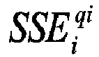
- a control point 30 is available. Each control point corresponds to a quantization parameter q i , to a coding cost COST i q i and to a distortion value D i q i (e.g. SSE i q i ) . From the SSE i q i , a quality value PSNR i q i is derived.
- each MB i with one quantization parameter out of two (i.e. 2, 4, ..., q i , q i +2, q i +4, ).
- the whole curve as depicted on figure 3 and thus the whole map as depicted on figure 2 are then constructed, for each MB i , for example by a cubic or spline interpolation. It is also possible to only build a portion of the curve around the reference quantization parameter q T .
- Another way to model this curve consists in using the statistical properties of the source data. Such statistical models are mainly based on the fact that the source image is a Gaussian source. The different parameters of the Gaussian model, i.e. the variance and the average, are directly estimated from the source data.
- the third step 12 consists in allocating a minimum number of bits per MB i in order to reach a desired minimum video quality depending on the image content.
- This minimum video quality is specified by external means either automatically or manually (e.g. by a broadcaster).
- the detailed flowchart of this step is depicted on figure 4.
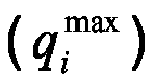
- the objective of step 12 is to determine a preliminary quantization parameter q i max for each MB i , higher than the reference quantization parameter q T in order to save a number of bits R interest when encoding MB i with q i max . Saved number of bits R interest can be further allocated to regions of interest.
- external means are setting a quality parameter ⁇ ( ⁇ ⁇ [0,1]) in function of the picture/video content.
- PSNR i q T the reference quality value that can be tolerated for the target application.
- ⁇ is set about 0.75.
- ⁇ should be close to one in order to avoid artifacts apparition on the background.
- ⁇ can be small in order to improve dramatically the quality over the regions of interest.
- the minimum image quality PSNR i min that can be tolerated equals ⁇ PSNR i q T , where PSNR i q T is the PSNR value associated to MB i when it has been quantized with parameter q T .
- the minimum image quality ⁇ PSNR i q T corresponds to a maximum distortion value D i max .
- the value ⁇ can be constant per video sequence, per picture, or set adaptively for each MB i (for example by taking into account spatial properties and spatial masking capabilities of the MB).
- Each quantization parameter q i associated to MB i is initialized to q T .
- Step 120 consists for a MB i in increasing q i by a value j (0 ⁇ j ⁇ N) until PSNR i q T + j PSNR i q T ⁇ ⁇ .
- the last q i value is referenced below as q i max and corresponds to a distortion value D i q i max as defined on figure 3.
- the associated coding cost COST i q i max is derived from the rate distortion map.
- the picture coding cost R min is thus obtained by summing the coding COST i q i max over the whole picture. It corresponds to the minimum number of bits required to reach the minimum picture quality set by external means.
- the distribution of such quantity over the regions of interest is depending on side-information for example saliency maps.
- a minimal quantization value q i * has to be selected for each MB i depending on side information.
- the optimum value of quantization q i * for a MB i will be then lower than or equal to q i max .
- the relaxation factor, noted ⁇ i ranges from 0 to 1 : the closer ⁇ i to 0, the more the MB i is considered to be a relevant perceptual area.
- ⁇ i can be obtained using saliency maps as described by O. Le Meur et al., entitled “Performance assessment of a visual attention system entirely based on a human vision modeling” and published in Proceedings of ICIP in October 2004.
- the saliency map is providing a saliency value s(x,y) per pixel (where (x,y) denotes the pixel coordinates) that characterized its perceptual relevancy. The higher the s(x,y) value is, the more revealant the pixel of coordinates (x,y) is.
- S i per MB i it is thus possible to average the values over MB i or to take the median value over MB i .
- the saliency values S i are further normalized so that they belong to the range [0;1]. Finally, the value ⁇ i is set equal to (1- S i ).
- the optimal solution Q* is determined by optimizing equation (1) using the bisection method described in an article by Y. Shoham et al. entitled “Efficient bit allocation for an arbitrary set of quantizers", IEEE Trans. Acoust., Speech, Signal Processing, vol. 36, pp. 1445-1453. Other methods as dynamic programming approach can be used. In other cases, more complex approaches can be used as the one described in "Bit allocation for dependent quantization with applications to multiresoltuion and MPEG video coders", IEEE Trans. Image Proc., vol. 3, n°5, pp.
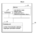
- the invention concerns also a device depicted on figure 5 that implements the method described previously. Only the basic elements of the device are represented on figure 5.
- the device according to the invention includes a memory 52.
- the rate-distortion maps, the quality parameter the reference quantization step qnd the saliency maps are stored in this memory.
- the device includes also a processing unit 53 as a microprocessor or a similar element. This unit implements the processing softwares as the number of bits allocation softwares and the Lagrangian optimization software. These softwares use the parameters stored into the memory.
- the device includes an input/output interface 51 to receive the input video signal, and to transmit the signal processed by the method 12, 13 according to the invention. This device can be further included in an video encoder.
Landscapes
- Engineering & Computer Science (AREA)
- Multimedia (AREA)
- Signal Processing (AREA)
- Physics & Mathematics (AREA)
- Algebra (AREA)
- General Physics & Mathematics (AREA)
- Mathematical Analysis (AREA)
- Mathematical Optimization (AREA)
- Pure & Applied Mathematics (AREA)
- Compression Or Coding Systems Of Tv Signals (AREA)
Abstract
The invention concerns a method for selecting a quantization parameter for each pixel group in a picture. The quantization parameters are used for encoding the picture into a first number of bits (R). The method comprises:
- A first step (11, 12) for computing a preliminary quantization parameter

- A second step (13, 14) for computing a final quantization parameter
Description
- The invention relates to a method and a device for selecting quantization parameters for each pixel group in a picture based on side information. These quantization parameters are further used for encoding this picture into a number of bits (R).
- Selective video compression scheme allows to have a spatial variation of the bit rate, and therefore a spatial variation of the perceived video quality, across pictures. For example, in the case of MPEG2 or MPEG4 standards, the quantization parameter used to encode each picture can vary within the picture at a macroblock or block level. In this way, the relevant areas of the pictures can be encoded at a higher quality than the non relevant areas. In the case of a video conference application, the background can be considered as a non relevant area while the head and shoulders of the speaker are considered as relevant areas. The aim of such a non homogeneous allocation of the number of bits is to significantly improve the overall perceived video quality. Therefore, in order to allocate a number of bits depending on spatial information, it is needed first to identify regions of interest and second to allocate more bits to these regions.
The identification of regions of interest can be based for example on a computational model of bottom-up visual selective attention described in an article by O. Le Meur et al., entitled "Performance assessment of a visual attention system entirely based on a human vision modeling" and published in Proceedings of ICIP in October 2004.
Afterwards, more bits are allocated to encode these identified regions in order to improve their quality. In the article entitled "A ROI approach for hybrid image sequence coding", in Proc. IEEE International Conference on Image Processing, Vol.3, pp.245-249, Nov. 1994, E. Nguyen et al. use a hierarchy of regions of interest obtained from a motion-based segmentation and a weighted rate-distortion function in order to optimize the allocation of the number of bits. Other solutions as the one proposed by A. Leontaris et al. in "Region-of-interest video compression with a composite and a long-term frame", in Proc. 7th LASTED, International Conference on Computer Graphics and Imaging, Hawaï, August 17-19, 2004, consist in relaxing the number of bits constraint in the rate-distortion optimization depending on a factor which depends on the interest of the region. Thus, for a region of interest, this factor tends to zero in order to minimize the distortion term for this region. For a non relevant region, this factor is increased in order to minimize the coding cost (i.e. the number of bits used to encode this region) of this region.
At medium bit rate, in a context of video broadcast for example, these methods introduce very annoying spatio-temporal artifact in the background of the pictures. Indeed, a spatio-temporal artifact can effortlessly grab our visual attention creating therefore a fixation point. This affects the overall perceived video quality which is thus debased. - The invention aims at reaching the best trade-off between the video quality of relevant versus non relevant areas of the video sequence.
- The invention concerns a method for selecting a quantization parameter for each pixel group in a picture. The quantization parameters are used for encoding the picture into a first number of bits (R). The method comprises:
- A first step for computing a preliminary quantization parameter

- A second step for computing a final quantization parameter

- The first step of the method according to the invention comprises the following sub-steps of:
- Associating a rate distortion map to each pixel group, the rate distortion map associating to each quantization parameter a distortion value and a number of bits;
- Computing a preliminary quantization parameter


- Computing a second number of bits (Rmin) by summing the number of bits associated to the preliminary quantization parameters and given by the corresponding rate distortion map;
- According to a preferred embodiment, the rate distortion map associated to a group of pixels is computed by encoding the group of pixels with various quantization parameters and by computing for each quantization parameter the distortion value and the number of bits value resulting from this encoding.
Advantageously, the rate distortion map is computed for a reduced number of quantization parameters and in that it is supplemented by interpolating missing distortion values and missing number of bits values from computed distortion values and number of bits values using an interpolation function.
According to the invention, the maximum distortion value


- Preferentially, the perceptual relevancy for a pixel group is characterized by a saliency map computed for this pixel group.
- According to a particular embodiment, a pixel group is a block of 16x16 pixels.
- The invention also concerns a device for selecting a quantization parameter for each pixel group in a picture. The quantization parameters are used for encoding the picture into a first number of bits (R). The device comprises:
- a memory for storing rate distortion maps associated to each pixel group, the rate distortion map associating to each quantization parameter a distortion value and a number of bits; and
- a processing unit for computing a preliminary quantization parameter


- Other features and advantages of the invention will appear with the following description of some of its embodiments, this description being made in connection with the drawings in which:
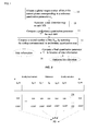
- Figure 1 depicts the general flowchart of the method according to the invention;
- Figure 2 depicts a rate distortion map;
- Figure 3 depicts a rate distortion function where the rate is represented on the abscissa and the distortion is represented on the ordinate;
- Figure 4 depicts the flowchart of the third step of the method according to the invention; and
- Figure 5 depicts a device according to the invention.
- The invention concerns a method depicted on figure 1 supervised by external means (e.g. a broadcaster). In Figure 1, the represented boxes are purely functional entities, which do not necessarily correspond to physical separated entities. Namely, they could be developed in the form of software, or be implemented in one or several integrated circuits. The objective of the invention is to reach the best trade-off between the video quality of relevant versus non relevant areas of the video sequence in order to improve the overall perceived video quality without introducing any spatio-temporal artifact. More particularly, it consists, from a reference quality level, in decreasing the quality to a minimum desired quality level specified in function of picture or video sequence content and in reallocating saved number of bits on the regions of interest.
- The method according to the invention can be applied to a single picture or a video sequence of several pictures. Each picture is divided into K pixel groups, Ui, i∈ [1,K]. Each pixel group can be for example a macroblock (MBi), i.e. a block of 16x16 pixels or more generally a block of NxN pixels. For sake of clarity, the pixel group is defined as a MB hereinafter.
Several quality metrics are used below to estimate the distortion between an original image and corresponding coded image. The sum of squared errors (SSE) is defined for a MB as the sum over the whole MB of the squared differences between the original pixel values and the corresponding reconstructed pixel values after encoding the MB. The mean squared error (MSE) equals the SSE divided by the number of samples (i.e. pixels values). The peak signal-to-noise ratio (PSNR) can be deduced from the MSE and thus from SSE by the following formula:
- In figure 1, the
first step 10 consists in allocating a global target number of bits R to the current picture being encoded in order to reach a reference quality level. The value of R is determined for example by a rate control module as the one defined in ISO/IEC JTC1/SC29/WG11, Test model 5, 1993. This value can vary for example depending on the picture encoding type (e.g. intra picture, predictive picture). Indeed, a higher value of R is allocated for an intra coded picture (i.e. a picture in a video sequence coded without referencing any other picture) than for a predicted coded picture (i.e. a picture in a video sequence coded with reference to a previously encoded picture).
This global number of bits R can be reached by encoding the current picture with a single reference quantization parameter qT, i.e. the same parameter for all MBi. The value of qT referenced on figure 3 can be determined from the value R and rate distortion maps as thus build at next step or can be directly provided by the rate control module. A reference quality value (e.g.

The method according to the invention consists in sharing this global number of bits R into a minimum number of bits Rmin in order to insure a minimum picture/video quality and a remaining number of bits Rinterest, i.e. R= Rmin+Rinterest, in order to improve this quality on regions of interest. - In reference to figure 1, the
second step 11 consists in associating a rate-distortion map to each MBi in the current picture. A rate-distortion map for a given MBi is depicted on figure 2. To this map corresponds a rate-distortion function as depicted on figure 3. The map building consists in associating to each quantization step size in a given range (e.g. [0-31]) specified by the coding standard, avector 20 of two parameters: a distortion value 21 (e.g. SSE) and a coding cost (i.e. a number of bits) 22. A coding cost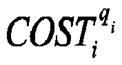
control point 30 is available. Each control point corresponds to a quantization parameter qi, to a coding cost



- The
third step 12 consists in allocating a minimum number of bits per MBi in order to reach a desired minimum video quality depending on the image content. This minimum video quality is specified by external means either automatically or manually (e.g. by a broadcaster). The detailed flowchart of this step is depicted on figure 4.
The objective ofstep 12 is to determine a preliminary quantization parameter

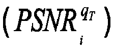


Each quantization parameter q i associated to MBi is initialized to qT. Step 120 consists for a MBi in increasing q i by a value j (0≤j≤N) until


- At
step 13, the picture coding cost Rmin is thus obtained by summing the coding
- In a
fifth step 14, the saved number of bits Rinterest = R-Rmin duringprevious step 12 is used to improve picture quality over identified regions of interest. The distribution of such quantity over the regions of interest is depending on side-information for example saliency maps. The goal of this step is to find, among all the possible quantization combinations Q= (q 1, ... , q K ), where q i denotes the quantization selected for MBi, the optimal solution

To solve this constrained optimization problem, a widely used method firstly emphazised by Shoham et al. in "Efficient bit allocation for an arbitrary set of quantizers", IEEE Trans. Acoust., Speech, Signal Processing, vol. 36, pp. 1445-1453, Sept. 1988, is the Lagrange multiplier method. It consists in transforming the constraint problem in an unconstraint problem by computing the following Lagrangian cost:
where λ is the Lagrange multiplier.
Assuming that the rate-distortion is convex, the problem above can be written as the following equivalent problem:
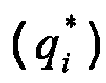
Consequently, the global optimization can now be carried out independently for each MBi. Thestep 13 thus consists in adapting the range of the quantization trials dynamically. A minimal quantization value qi* has to be selected for each MBi depending on side information. The optimum value of quantization qi* for a MBi will be then lower than or equal to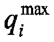

The relaxation factor, noted θ i , ranges from 0 to 1 : the closer θ i to 0, the more the MBi is considered to be a relevant perceptual area. θ i can be obtained using saliency maps as described by O. Le Meur et al., entitled "Performance assessment of a visual attention system entirely based on a human vision modeling" and published in Proceedings of ICIP in October 2004. The saliency map is providing a saliency value s(x,y) per pixel (where (x,y) denotes the pixel coordinates) that characterized its perceptual relevancy. The higher the s(x,y) value is, the more revelant the pixel of coordinates (x,y) is. In order to get a single saliency value Si per MBi it is thus possible to average the values over MBi or to take the median value over MBi. The saliency values Si are further normalized so that they belong to the range [0;1]. Finally, the value θ i is set equal to (1- Si).
The optimal solution Q* is determined by optimizing equation (1) using the bisection method described in an article by Y. Shoham et al. entitled "Efficient bit allocation for an arbitrary set of quantizers", IEEE Trans. Acoust., Speech, Signal Processing, vol. 36, pp. 1445-1453. Other methods as dynamic programming approach can be used. In other cases, more complex approaches can be used as the one described in "Bit allocation for dependent quantization with applications to multiresoltuion and MPEG video coders", IEEE Trans. Image Proc., vol. 3, n°5, pp. 533-545, sep. 1994 by K. Ramchandran et al. This step allows to reallocate the number of bits Rinterest over the various MBi depending on their perceptual relevancy so that the number of bits used to encode the whole picture does not exceed the value R specified by external means (e.g. rate control module). - The invention concerns also a device depicted on figure 5 that implements the method described previously. Only the basic elements of the device are represented on figure 5. The device according to the invention includes a
memory 52. The rate-distortion maps, the quality parameter the reference quantization step qnd the saliency maps are stored in this memory. The device includes also aprocessing unit 53 as a microprocessor or a similar element. This unit implements the processing softwares as the number of bits allocation softwares and the Lagrangian optimization software. These softwares use the parameters stored into the memory. Besides, the device includes an input/output interface 51 to receive the input video signal, and to transmit the signal processed by themethod
This device can be further included in an video encoder.

Claims (11)
- Method for selecting a quantization parameter for each pixel group in a picture, said quantization parameters being used for encoding said picture into a first number of bits (R), characterized in that it comprises:- A first step (11, 12) for computing a preliminary quantization parameter
 - A second step (13, 14) for computing a final quantization parameter
- Method according to claim 1, characterized in that the first step comprises the following sub-steps:- Associating (11) a rate distortion map to each pixel group, said rate distortion map associating to each quantization parameter a distortion value and a number of bits;- Computing (12) a preliminary quantization parameterand in that the second step further comprises, before computing (14) the final quantization parameter


 - Computing (13) the second number of bits (Rmin) by summing the number of bits associated to said preliminary quantization parameters and given by the corresponding rate distortion map.
 - Method according to claim 2, characterized in that the rate distortion map associated to a group of pixels is computed by encoding said group of pixels with various quantization parameters and by computing for each quantization parameter the distortion value and the number of bits value resulting from this encoding.
- Method according to claim 3, characterized in that the rate distortion map is computed for a reduced number of quantization parameters and in that it is supplemented by interpolating missing distortion values and missing number of bits values from computed distortion values and number of bits values using an interpolation function.
- Method according to any of claims 2 to 4, characterized in that said maximum distortion value

- Method according to any of claims 2 to 5, characterized in that said minimum picture quality is defined as a minimum peak signal-to-noise ratio value

- Method according to claim 6, characterized in that said minimum quality value


- Method according to any of claim 1 to 7, characterized in that the perceptual relevancy for a pixel group is characterized by a saliency map computed for this pixel group.
- Method according to any of claims 1 to 8, characterized in that a pixel group is a block of 16x16 pixels.
- Device for selecting a quantization parameter for each pixel group in a picture, said quantization parameters being used for encoding said picture into a first number of bits (R), characterized in that it comprises:- a memory (52) for storing rate distortion maps associated to each pixel group, said rate distortion map associating to each quantization parameter a distortion value and a number of bits; and- a processing unit (53) for computing a preliminary quantization parameter


- Device according to claim 10, characterized in that it is used to implement the method according to any of claims 1 to 9.
Priority Applications (2)
| Application Number | Priority Date | Filing Date | Title |
|---|---|---|---|
| EP05100189A EP1679659A1 (en) | 2005-01-06 | 2005-01-13 | Method and device for selecting quantization parameters in a picture using side information |
| PCT/EP2005/056715 WO2006072536A1 (en) | 2005-01-06 | 2005-12-13 | Method and device for selecting quantization parameters in a picture using side information |
Applications Claiming Priority (2)
| Application Number | Priority Date | Filing Date | Title |
|---|---|---|---|
| EP05290040 | 2005-01-06 | ||
| EP05100189A EP1679659A1 (en) | 2005-01-06 | 2005-01-13 | Method and device for selecting quantization parameters in a picture using side information |
Publications (1)
| Publication Number | Publication Date |
|---|---|
| EP1679659A1 true EP1679659A1 (en) | 2006-07-12 |
Family
ID=36095879
Family Applications (1)
| Application Number | Title | Priority Date | Filing Date |
|---|---|---|---|
| EP05100189A Withdrawn EP1679659A1 (en) | 2005-01-06 | 2005-01-13 | Method and device for selecting quantization parameters in a picture using side information |
Country Status (2)
| Country | Link |
|---|---|
| EP (1) | EP1679659A1 (en) |
| WO (1) | WO2006072536A1 (en) |
Cited By (5)
| Publication number | Priority date | Publication date | Assignee | Title |
|---|---|---|---|---|
| EP2549754A1 (en) * | 2011-07-19 | 2013-01-23 | Thomson Licensing | Method and apparatus for reframing and encoding an original video signal |
| EP2582136A1 (en) * | 2011-10-12 | 2013-04-17 | Thomson Licensing | Saliency value determination of predictively encoded video streams |
| EP3403401A4 (en) * | 2016-01-12 | 2019-06-12 | Shanghaitech University | COMPRESSION METHOD AND APPARATUS FOR PANORAMIC STEREOSCOPIC VIDEO SYSTEM |
| CN116132545A (en) * | 2022-12-14 | 2023-05-16 | 浙江大学 | Time sequence data compression and reconstruction method based on graph signal processing |
| US12400368B2 (en) | 2021-12-08 | 2025-08-26 | Axis Ab | Encoding device and a method for encoding an image frame including selective restriction of offset compression values |
-
2005
- 2005-01-13 EP EP05100189A patent/EP1679659A1/en not_active Withdrawn
- 2005-12-13 WO PCT/EP2005/056715 patent/WO2006072536A1/en not_active Ceased
Non-Patent Citations (4)
| Title |
|---|
| CHAI D ET AL: "Foreground/background bit allocation for region-of-interest coding", IMAGE PROCESSING, 2000. PROCEEDINGS. 2000 INTERNATIONAL CONFERENCE ON SEPTEMBER 10-13, 2000, PISCATAWAY, NJ, USA,IEEE, vol. 2, 10 September 2000 (2000-09-10), pages 923 - 926, XP010530136, ISBN: 0-7803-6297-7 * |
| SENGUPTA S ET AL: "Enhancing selected facial features in very low bit-rate video sequences", PROCEEDINGS 2001 INTERNATIONAL CONFERENCE ON IMAGE PROCESSING. ICIP 2001. THESSALONIKI, GREECE, OCT. 7 - 10, 2001, INTERNATIONAL CONFERENCE ON IMAGE PROCESSING, NEW YORK, NY : IEEE, US, vol. VOL. 1 OF 3. CONF. 8, 7 October 2001 (2001-10-07), pages 485 - 488, XP010564902, ISBN: 0-7803-6725-1 * |
| SENGUPTA S ET AL: "Percetually motivated bit-allocation for H.264 encoded video sequences", PROCEEDINGS 2003 INTERNATIONAL CONFERENCE ON IMAGE PROCESSING. ICIP-2003. BARCELONA, SPAIN, SEPT. 14 - 17, 2003, INTERNATIONAL CONFERENCE ON IMAGE PROCESSING, NEW YORK, NY : IEEE, US, vol. VOL. 2 OF 3, 14 September 2003 (2003-09-14), pages 797 - 800, XP010669954, ISBN: 0-7803-7750-8 * |
| SHOHAM Y ET AL: "EFFICIENT BIT ALLOCATION FOR AN ARBITRARY SET OF QUANTIZERS", IEEE TRANSACTIONS ON ACOUSTICS, SPEECH AND SIGNAL PROCESSING, IEEE INC. NEW YORK, US, vol. 36, no. 9, 1 September 1988 (1988-09-01), pages 1445 - 1453, XP000606108, ISSN: 0096-3518 * |
Cited By (13)
| Publication number | Priority date | Publication date | Assignee | Title |
|---|---|---|---|---|
| US9641795B2 (en) | 2011-07-19 | 2017-05-02 | Thomson Licensing Dtv | Method and apparatus for reframing and encoding a video signal |
| WO2013010751A1 (en) * | 2011-07-19 | 2013-01-24 | Thomson Licensing | Method and apparatus for reframing and encoding a video signal |
| CN103688538B (en) * | 2011-07-19 | 2017-05-31 | 汤姆逊许可公司 | Method and apparatus for reconstructing and encoding a video signal |
| EP2549754A1 (en) * | 2011-07-19 | 2013-01-23 | Thomson Licensing | Method and apparatus for reframing and encoding an original video signal |
| US20140153651A1 (en) * | 2011-07-19 | 2014-06-05 | Thomson Licensing | Method and apparatus for reframing and encoding a video signal |
| EP2582134A1 (en) * | 2011-10-12 | 2013-04-17 | Thomson Licensing | Saliency value determination of predictively encoded video streams |
| EP2582136A1 (en) * | 2011-10-12 | 2013-04-17 | Thomson Licensing | Saliency value determination of predictively encoded video streams |
| EP3403401A4 (en) * | 2016-01-12 | 2019-06-12 | Shanghaitech University | COMPRESSION METHOD AND APPARATUS FOR PANORAMIC STEREOSCOPIC VIDEO SYSTEM |
| US10489886B2 (en) | 2016-01-12 | 2019-11-26 | Shanghaitech University | Stitching method and apparatus for panoramic stereo video system |
| US10636121B2 (en) | 2016-01-12 | 2020-04-28 | Shanghaitech University | Calibration method and apparatus for panoramic stereo video system |
| US10643305B2 (en) | 2016-01-12 | 2020-05-05 | Shanghaitech University | Compression method and apparatus for panoramic stereo video system |
| US12400368B2 (en) | 2021-12-08 | 2025-08-26 | Axis Ab | Encoding device and a method for encoding an image frame including selective restriction of offset compression values |
| CN116132545A (en) * | 2022-12-14 | 2023-05-16 | 浙江大学 | Time sequence data compression and reconstruction method based on graph signal processing |
Also Published As
| Publication number | Publication date |
|---|---|
| WO2006072536A1 (en) | 2006-07-13 |
Similar Documents
| Publication | Publication Date | Title |
|---|---|---|
| JP4187405B2 (en) | Object-based rate control apparatus and method in coding system | |
| US6690833B1 (en) | Apparatus and method for macroblock based rate control in a coding system | |
| US6496607B1 (en) | Method and apparatus for region-based allocation of processing resources and control of input image formation | |
| Chen et al. | ROI video coding based on H. 263+ with robust skin-color detection technique | |
| EP0960532B1 (en) | Apparatus and method for optimizing the rate control in a coding system | |
| EP1938613B1 (en) | Method and apparatus for using random field models to improve picture and video compression and frame rate up conversion | |
| EP2160903B1 (en) | A buffer-based rate control exploiting frame complexity, buffer level and position of intra frames in video coding | |
| US6980695B2 (en) | Rate allocation for mixed content video | |
| US6011864A (en) | Digital image coding system having self-adjusting selection criteria for selecting a transform function | |
| US6650705B1 (en) | Method for encoding and transcoding multiple video objects with variable temporal resolution | |
| US7697783B2 (en) | Coding device, coding method, decoding device, decoding method, and programs of same | |
| US20040202248A1 (en) | Control strategy for dynamically encoding multiple streams of video data in parallel for multiplexing onto a constant bit rate channel | |
| KR101194518B1 (en) | Method for locally adjusting a quantization step | |
| US20070019874A1 (en) | Method and apparatus for scalable signal processing | |
| EP1523195A2 (en) | Method and apparatus for decoding digital image data | |
| US20070165718A1 (en) | Encoding apparatus, encoding method and program | |
| WO2006072536A1 (en) | Method and device for selecting quantization parameters in a picture using side information | |
| Chung et al. | Quantization control for improvement of image quality compatible with MPEG2 | |
| US6606414B1 (en) | Method and device for coding a digitized image | |
| Chi et al. | H. 263+ region-of-interest video coding with efficient skin-color extraction | |
| Paek et al. | Rate control strategy based on human visual sensitivity for MPEG video coder | |
| Guillotel et al. | Perceptual video coding based on MB classification and rate–distortion optimization | |
| CN101310534A (en) | Method and apparatus for improving picture and video compression and frame rate up-conversion using random domain model | |
| US8064526B2 (en) | Systems, methods, and apparatus for real-time encoding | |
| Cai | Video Coding Strategies for Machine Comprehension |
Legal Events
| Date | Code | Title | Description |
|---|---|---|---|
| PUAI | Public reference made under article 153(3) epc to a published international application that has entered the european phase |
Free format text: ORIGINAL CODE: 0009012 |
|
| AK | Designated contracting states |
Kind code of ref document: A1 Designated state(s): AT BE BG CH CY CZ DE DK EE ES FI FR GB GR HU IE IS IT LI LT LU MC NL PL PT RO SE SI SK TR |
|
| AX | Request for extension of the european patent |
Extension state: AL BA HR LV MK YU |
|
| AKX | Designation fees paid | ||
| REG | Reference to a national code |
Ref country code: DE Ref legal event code: 8566 |
|
| STAA | Information on the status of an ep patent application or granted ep patent |
Free format text: STATUS: THE APPLICATION IS DEEMED TO BE WITHDRAWN |
|
| 18D | Application deemed to be withdrawn |
Effective date: 20070113 |