EP1679400A1 - Drum of drum type washing machine - Google Patents
Drum of drum type washing machine Download PDFInfo
- Publication number
- EP1679400A1 EP1679400A1 EP05015672A EP05015672A EP1679400A1 EP 1679400 A1 EP1679400 A1 EP 1679400A1 EP 05015672 A EP05015672 A EP 05015672A EP 05015672 A EP05015672 A EP 05015672A EP 1679400 A1 EP1679400 A1 EP 1679400A1
- Authority
- EP
- European Patent Office
- Prior art keywords
- drum
- lift
- reinforcing
- seam portion
- seaming portion
- Prior art date
- Legal status (The legal status is an assumption and is not a legal conclusion. Google has not performed a legal analysis and makes no representation as to the accuracy of the status listed.)
- Withdrawn
Links
- 238000005406 washing Methods 0.000 title claims abstract description 38
- 238000004826 seaming Methods 0.000 claims abstract description 110
- 230000003014 reinforcing effect Effects 0.000 claims description 115
- 238000001035 drying Methods 0.000 description 4
- 239000000463 material Substances 0.000 description 3
- XLYOFNOQVPJJNP-UHFFFAOYSA-N water Substances O XLYOFNOQVPJJNP-UHFFFAOYSA-N 0.000 description 3
- 239000003599 detergent Substances 0.000 description 1
- 238000000034 method Methods 0.000 description 1
- 239000000126 substance Substances 0.000 description 1
Images






Classifications
-
- D—TEXTILES; PAPER
- D06—TREATMENT OF TEXTILES OR THE LIKE; LAUNDERING; FLEXIBLE MATERIALS NOT OTHERWISE PROVIDED FOR
- D06F—LAUNDERING, DRYING, IRONING, PRESSING OR FOLDING TEXTILE ARTICLES
- D06F37/00—Details specific to washing machines covered by groups D06F21/00 - D06F25/00
- D06F37/02—Rotary receptacles, e.g. drums
- D06F37/04—Rotary receptacles, e.g. drums adapted for rotation or oscillation about a horizontal or inclined axis
-
- D—TEXTILES; PAPER
- D06—TREATMENT OF TEXTILES OR THE LIKE; LAUNDERING; FLEXIBLE MATERIALS NOT OTHERWISE PROVIDED FOR
- D06F—LAUNDERING, DRYING, IRONING, PRESSING OR FOLDING TEXTILE ARTICLES
- D06F37/00—Details specific to washing machines covered by groups D06F21/00 - D06F25/00
- D06F37/02—Rotary receptacles, e.g. drums
-
- D—TEXTILES; PAPER
- D06—TREATMENT OF TEXTILES OR THE LIKE; LAUNDERING; FLEXIBLE MATERIALS NOT OTHERWISE PROVIDED FOR
- D06F—LAUNDERING, DRYING, IRONING, PRESSING OR FOLDING TEXTILE ARTICLES
- D06F37/00—Details specific to washing machines covered by groups D06F21/00 - D06F25/00
- D06F37/02—Rotary receptacles, e.g. drums
- D06F37/04—Rotary receptacles, e.g. drums adapted for rotation or oscillation about a horizontal or inclined axis
- D06F37/06—Ribs, lifters, or rubbing means forming part of the receptacle
Definitions
- the present invention relates to a drum washing machine, and more particularly, to a drum of a drum washing machine, in which the drum has sufficient strength to be used in a drum washing machine of high speed and large volume.
- a washing machine is utilized to wash the laundry based on action of flow of washing water and chemical action of detergents.
- the washing machine selectively or entirely performs washing, hot water washing, rinsing, and dehydrating (or drying) depending on user's selection.
- a drum 1 of the related art drum washing machine has a cylindrical shape.
- the drum 1 is provided with a plurality of through holes 1a to enable washing water to flow in and out. Both circumferential ends of the drum 1 are seamed to form a cylindrical shape.
- a seaming portion 10 of the drum 1 is formed in a direction substantially parallel to a rotational shaft of the drum 1.
- the seaming portion 10 protrudes on the outer circumference of the drum 1 and is pressurized by a punch at a predetermined interval to form a concave and convex shape.
- the seaming portion 10 of the drum 1 will be described in more detail with reference to FIG. 3.
- One circumferential end of the drum 1 is externally folded to form a folding portion 11, and the other circumferential of the drum 1 is internally folded to form a folding portion 12.
- the folding portions 11 and 12 are pressurized to comprise the seaming portion 10 when they are fitted into each other.
- the aforementioned drum washes, rinses, and dehydrates (or dries) the laundry while being rotated by a driving gear.
- tension F acts on the seaming portion 10 of the drum 1 in both circumferential directions as shown in FIG. 4. Particularly, great tension F acts on the seaming portion 10 during a dehydrating or drying process in which the drum 1 is rotated at high speed.
- the drum has a structure that tension F remarkably acts on a portion P1 where an upper folding portion starts, a problem occurs in that the portion P1 may be unfolded as shown in a dotted line of FIG. 5A if tension F remarkably acts on the portion P1 for a long time.
- the seaming portion has weak rigidity, it is likely that the seaming portion is unfolded or distorted as described above. This makes the seaming portion difficult to be applied to or utilized in the drum of high speed and large volume.
- the laundry in the drum may be damaged due to snagging caused by the seaming portion when the drum is rotated.
- the present invention is directed to provide a drum of a drum washing machine that substantially obviates one or more problems due to limitations and disadvantages of the related art.
- An object of the present invention is to provide a drum of a drum washing machine in which a seaming portion of the drum is prevented from being unfolded or distorted and the drum can be used in a drum washing machine of high speed and large volume.
- Another object of the present invention is to provide a drum of a drum washing machine in which the laundry is prevented from being damaged by a seaming portion during washing and drying cycles of the laundry.
- a drum of a drum washing machine includes a body having a seaming portion whose both circumferential ends are connected with each other, and a reinforcing device fixed onto the seaming portion to disperse tension in a circumferential direction, which acts on the seaming portion.
- the reinforcing device includes reinforcing panels arranged on the seaming portion, and fitting members fitting the reinforcing panels to the body to disperse the tension into the reinforcing panels and the seaming portion.
- the fitting members are arranged at both circumferential sides around the seaming portion.
- the reinforcing panels are arranged on outer and inner surfaces of the seaming portion.
- the reinforcing panels are arranged on either an inner surface or an outer surface of the seaming portion.
- the lift is arranged to correspond to the seaming portion of the body and the lift is provided with a groove to receive one end of each of the fitting members.
- the fitting members are fitted into the lift through the body and the reinforcing panels to disperse the tension into the body, the reinforcing panels and the lift.
- the fitting members pass through the body and the reinforcing panels to disperse the tension into the body and the reinforcing panels, and are not fitted into the lift.
- the fitting members are bolts or rivets.
- a drum of a drum washing machine includes a body having a seaming portion whose both circumferential ends are connected with each other, the seaming portion being externally protruded, a reinforcing device fixed onto the seaming portion to disperse tension in a circumferential direction, which acts on the seaming portion, and a lift arranged to correspond to the seaming portion.
- a drum of a drum washing machine in another aspect of the present invention, includes a body having a seaming portion whose both circumferential ends are connected with each other.
- the seaming portion protrudes internally, a reinforcing device is fixed onto the seaming portion to disperse tension in a circumferential direction, which acts on the seaming portion, and a lift receiving the seaming portion therein.
- a drum of a drum washing machine includes a body having a seaming portion whose both circumferential ends are connected with each other, the seaming portion internally protruding, and a lift receiving the seaming portion therein.
- a drum of a drum washing machine according to the first embodiment of the present invention will be described with reference to FIG. 6.
- the drum includes a body 100 having a seaming portion 110 whose both circumferential ends are connected with each other, and a reinforcing device 310 fixed onto the seaming (or seam) portion 110 to disperse tension F in a circumferential direction, which acts on the seaming portion.
- the seaming portion 110 is provided in such a manner that the circumferential ends of the body 100 are connected to each other when they are bent.
- the seaming portion 110 may be bent in various shapes without being limited to the configuration of FIG. 6.
- both circumferential ends may be connected with each other such that they are bent twice or more.
- the seaming portion 110 is protruded at the outer side of the body 100.
- a lift 200 is preferably arranged to correspond to an inner side of the seaming portion 110.
- the lift 200 is to prevent the laundry from being damaged by shag (a snag) generated when the laundry contacts the seaming portion 110.
- the lift 200 has a filled inner portion or a hollow inner portion.
- the reinforcing device 310 is provided to surround the seaming portion 110. Various examples of the reinforcing device 310 will be described below.
- the first example of the reinforcing means 310 will be described in more detail with reference to FIG. 7.
- the reinforcing device 310 includes reinforcing panels 311 and 312 sequentially arranged on the seaming portion 110, and a fitting member 313 provided at both circumferential ends of the reinforcing panels to disperse tension F circumferentially acting on the body 100 between the reinforcing panels 311 and 312 and the seaming portion 110.
- the reinforcing panels 311 and 312 are sequentially arranged on inner and outer surfaces of the seaming portion 110.
- the reinforcing panels 311 and 312 have a width (circumferential length) greater than that of the seaming portion 110. This is to allow the reinforcing panels 311 and 312 to surround the seaming portion 110.
- both circumferential sides of the reinforcing panels 311 and 312 have a predetermined thickness to avoid distortion or splitting. The thickness of the reinforcing panels is determined while considering tension and volume of the drum.
- the lift 200 is preferably arranged to cover the reinforcing panel 312. This is to prevent the laundry from being damaged by the reinforcing panel 312 arranged on the inner surface of the seaming portion 110.
- the reinforcing panels 311 and 312 and the body 100 are made of the same material as each other in view of elasticity and contractile force, so that tension of the body 100 may be dispersed more efficiently.
- the reinforcing panels 311 and 312 may be made of a material different from that of the body 100 in view of elasticity and contractile force.
- fitting member 313 is fitted into the lift 200 through the reinforcing panels 311 and 312 and the body 100.
- a plurality of fitting members 313 are arranged at both circumferential sides of the seaming portion 110 along a length direction of the seaming portion.
- fitting member 313 As an example of the fitting member 313, a nut is fixed to the lift 200 and then a bolt is fitted into the nut. In this case, no separate fitting member is required to fix the lift 200 to the body 100 of the drum. Also, it is possible to prevent the fitting member 313 from being protruded toward the inner surface of the body 100.
- a bolt may directly be fixed to the lift.
- other types of fitting members may be used.
- the fitting member 315 pass through the reinforcing panels 311 and 312 and the body 100 but is not fitted to the lift 200.
- a groove 201 is formed at one side of the lift 200 toward the body to receive one end of the fitting member 313.
- Bolt and nut are used as the fitting member 315.
- a rivet is used as the fitting member 316. Since the fitting member 316 of FIG. 9 is substantially equal to that of FIG. 8 except that the rivet is used as the fitting member, its description will be omitted. It is to be understood that the rivet may be used in a structure that the groove of FIG. 8 is formed.
- the rivet passes through the reinforcing panels 311 and 312 and the body 100 but is not fitted into the lift 200.
- Tension F of the drum acts on the reinforcing device 310 along both circumferential sides. Particularly, great tension acts on the reinforcing device 310 during a drying cycle in which the drum is rotated at high speed.
- tension F is dispersed into the reinforcing panels 311 and 312, the seaming portion 110 and/or the lift 200 by the fitting members 313, 315, and 316.
- the outer reinforcing panel 311 surrounds the outer surface of the seaming portion 110 and the inner reinforcing panel 312 surrounds the inner surface of the seaming portion 110, it is possible to prevent the seaming portion from being unfolded.
- the inner reinforcing panel 312 is almost parallel to a direction of tension of the body 100, the inner reinforcing panel 312 can absorb tension of the body 100 more than the outer reinforcing panel 311 and the seaming portion 110.
- the fitting members 313, 315, and 316 and the inner reinforcing panel 312 are not exposed to the inner portion of the drum due to the lift 200, it is possible to prevent the laundry from contacting the fitting members 313, 315 and 316 and the reinforcing panel 312. Therefore, the laundry can be prevented from being damaged.
- the reinforcing panel 321 is arranged on the outer surface of the seaming portion 110. Therefore, the reinforcing means 320 is comprised of an outer reinforcing panel 321 and a fitting member 323.
- the reinforcing panel 321 surrounds the outer surface of the seaming portion 110 and the lift 200 surrounds the inner surface of the seaming portion 110, it is possible to prevent the seaming portion 110 from being unfolded.
- the fitting member 323 may fit or secure the reinforcing panel 321, the body 100 and the lift 200 or may fit or secure the reinforcing panel 321 and the body 100 only.
- the outer reinforcing panel 321 not only disperses tension but also prevents the seaming portion 110 from being unfolded.
- the reinforcing panel 332 is arranged on the inner surface of the seaming portion 110. Therefore, the reinforcing device 330 is comprised of an inner reinforcing panel 332 and a fitting member 333.
- the inner reinforcing panel 332 is substantially parallel to a direction of tension F of the body 100, the inner reinforcing panel 332 can absorb tension of the body 100 more than the seaming portion 110.
- the third example of the reinforcing device is more efficient than the second example in absorbing tension.
- fitting member 333 may fit or secure the reinforcing panel 332, the body 100 and the lift 200 or may fit or secure the reinforcing panel 332 and the body 100 only.
- a drum of a drum washing machine according to the second embodiment of the present invention will be described with reference to FIG. 12.
- the drum includes a body 100 having a seaming portion 110 whose both circumferential ends are connected with each other, the seaming portion 110 being internally protruded, a reinforcing device 410 is fixed onto the seaming portion 110 to disperse tension F in a circumferential direction, which acts on the seaming portion 110, and a lift 200 receives the seaming portion 110 therein.
- the lift 200 is provided with a receiving groove 210 to receive the seaming portion 110. It is to be understood that no separate receiving groove is required if the lift has a hollow structure.
- the reinforcing device 410 includes reinforcing panels 411 and 412 arranged on the seaming portion 110, and a fitting member 413 (see FIG. 13) to fit or secure the reinforcing panels to the body 100 to disperse tension F, which acts on the body in a circumferential direction, is provided between the reinforcing panels and the seaming portion.
- a first example of the reinforcing device 410 will be described with reference to FIG. 13.
- the reinforcing panels 411 and 412 are arranged to surround outer and inner surfaces of the seaming portion 110.
- the inner reinforcing panel 412 surrounds the inner surface of the seaming portion 110 while the outer reinforcing panel 411 surrounds the outer surface of the seaming portion 110.
- the protruded portion of the inner reinforcing panel 412 contacts the receiving groove 210 of the lift 200. Therefore, the lift 200 not only prevents the seaming portion 110 and the inner reinforcing panel 412 from being directly contacted with the laundry but also prevents the seaming portion from being unfolded.
- fitting member 413 is the same as that of the drum according to the first embodiment, its description will be omitted.
- a reinforcing panel 421 is arranged to surround the outer surface of the seaming portion 110.
- the lift 200 since the seaming portion 110 contacts the receiving groove 210 of the lift 200, the lift 200 not only prevents the seaming portion 110 from being unfolded but also prevents the seaming portion 110 from being contacted with the laundry.
- a fitting member 423 is fitted into the lift 200 through the reinforcing panel 421 and the body 100. Also, the fitting member 423 may not be fitted into the lift 200.
- a reinforcing panel 432 is arranged to surround the inner surface of the seaming portion 110. In this case, the seaming portion 110 and the protruded portion of the reinforcing panel 432 are received in the receiving groove 210 of the lift 200.
- a fitting member 433 is fitted into the lift 200 through the reinforcing panel 432 and the body 100.
- a drum of a drum washing machine according to the third embodiment of the present invention will be described with reference to FIG. 16.
- the drum includes a body 100 having a seaming portion 110 whose both circumferential ends are connected with each other, the seaming portion being internally protruded, and a lift 200 receiving the seaming portion 110 therein.
- the lift 200 is provided with a receiving groove 210 to receive the seaming portion 110.
- the lift 200 can prevent the seaming portion 110 from being unfolded or distorted without a separate reinforcing device.
- the third embodiment is different from the first and second embodiments in that tension acting on the seaming portion 110 is dispersed into the lift 200 only.
- the drum of the drum washing machine according to the present invention has the following advantages.
- tension acting on the seaming portion can remarkably (i.e., significantly) be reduced.
- the drum since tension acting on the seaming portion is reduced, the drum can be used in the drum washing machine of high speed and large volume.
- the lift is arranged to cover the seaming portion and the fitting member, it is possible to prevent the laundry from being damaged by the seaming portion and the fitting member.
- a drum washing machine having a seaming portion of the drum that is prevented from being unfolded or distorted even when the drum is rotated at high speed, by dispersing tension in a circumferential direction, which acts on the seaming portion.
- the seaming portion is provided with a lift to prevent the laundry from being damaged.
Landscapes
- Engineering & Computer Science (AREA)
- Textile Engineering (AREA)
- Main Body Construction Of Washing Machines And Laundry Dryers (AREA)
- Accessory Of Washing/Drying Machine, Commercial Washing/Drying Machine, Other Washing/Drying Machine (AREA)
Abstract
Description
- The present invention relates to a drum washing machine, and more particularly, to a drum of a drum washing machine, in which the drum has sufficient strength to be used in a drum washing machine of high speed and large volume.
- Generally, a washing machine is utilized to wash the laundry based on action of flow of washing water and chemical action of detergents. The washing machine selectively or entirely performs washing, hot water washing, rinsing, and dehydrating (or drying) depending on user's selection.
- Hereinafter, a drum of a related art drum washing machine will be described with reference to FIG. 1 to FIG. 5B.
- Referring to FIG. 1 and FIG. 2, a
drum 1 of the related art drum washing machine has a cylindrical shape. Thedrum 1 is provided with a plurality of throughholes 1a to enable washing water to flow in and out. Both circumferential ends of thedrum 1 are seamed to form a cylindrical shape. In this case, aseaming portion 10 of thedrum 1 is formed in a direction substantially parallel to a rotational shaft of thedrum 1. - As shown in FIG. 2, the
seaming portion 10 protrudes on the outer circumference of thedrum 1 and is pressurized by a punch at a predetermined interval to form a concave and convex shape. - The
seaming portion 10 of thedrum 1 will be described in more detail with reference to FIG. 3. - One circumferential end of the
drum 1 is externally folded to form a foldingportion 11, and the other circumferential of thedrum 1 is internally folded to form afolding portion 12. The foldingportions seaming portion 10 when they are fitted into each other. - The aforementioned drum washes, rinses, and dehydrates (or dries) the laundry while being rotated by a driving gear.
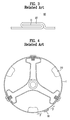
- When the
drum 1 is rotated, tension F acts on theseaming portion 10 of thedrum 1 in both circumferential directions as shown in FIG. 4. Particularly, great tension F acts on theseaming portion 10 during a dehydrating or drying process in which thedrum 1 is rotated at high speed. - However, the drum of the related art drum washing machine has several problems.
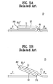
- First, since the drum has a structure that tension F remarkably acts on a portion P1 where an upper folding portion starts, a problem occurs in that the portion P1 may be unfolded as shown in a dotted line of FIG. 5A if tension F remarkably acts on the portion P1 for a long time.
- Second, greater tension F acts on a portion P2 where the upper folding portion ends, as the portion P1 is unfolded as shown in the dotted line of FIG. 5A. Therefore, force F1 acts on the upper folding portion in a direction where a lower folding portion is unfolded as shown in FIG. 5B. For this reason, a problem occurs in that a bent portion P3 of the lower folding portion is gradually unfolded as shown in FIG. 5B.
- Third, since the seaming portion has weak rigidity, it is likely that the seaming portion is unfolded or distorted as described above. This makes the seaming portion difficult to be applied to or utilized in the drum of high speed and large volume.
- Finally, since the lift is arranged to avoid the seaming portion, the laundry in the drum may be damaged due to snagging caused by the seaming portion when the drum is rotated.
- Accordingly, the present invention is directed to provide a drum of a drum washing machine that substantially obviates one or more problems due to limitations and disadvantages of the related art.
- An object of the present invention is to provide a drum of a drum washing machine in which a seaming portion of the drum is prevented from being unfolded or distorted and the drum can be used in a drum washing machine of high speed and large volume.
- Another object of the present invention is to provide a drum of a drum washing machine in which the laundry is prevented from being damaged by a seaming portion during washing and drying cycles of the laundry.
- Additional advantages, objects, and features of the invention will be set forth in part in the description which follows and in part will become apparent to those having ordinary skill in the art upon examination of the following or may be learned from practice of the invention. The objectives and other advantages of the invention may be realized and attained by the structure particularly pointed out in the written description and claims hereof as well as the appended drawings.
- To achieve these objects and other advantages and in accordance with the purpose of the invention, as embodied and broadly described herein, a drum of a drum washing machine includes a body having a seaming portion whose both circumferential ends are connected with each other, and a reinforcing device fixed onto the seaming portion to disperse tension in a circumferential direction, which acts on the seaming portion.
- Preferably, the reinforcing device includes reinforcing panels arranged on the seaming portion, and fitting members fitting the reinforcing panels to the body to disperse the tension into the reinforcing panels and the seaming portion.
- Preferably, the fitting members are arranged at both circumferential sides around the seaming portion.
- Preferably, the reinforcing panels are arranged on outer and inner surfaces of the seaming portion. Preferably, the reinforcing panels are arranged on either an inner surface or an outer surface of the seaming portion.
- Preferably, the lift is arranged to correspond to the seaming portion of the body and the lift is provided with a groove to receive one end of each of the fitting members.
- Preferably, the fitting members are fitted into the lift through the body and the reinforcing panels to disperse the tension into the body, the reinforcing panels and the lift. Preferably, the fitting members pass through the body and the reinforcing panels to disperse the tension into the body and the reinforcing panels, and are not fitted into the lift.
- Preferably, the fitting members are bolts or rivets.
- In another aspect of the present invention, a drum of a drum washing machine includes a body having a seaming portion whose both circumferential ends are connected with each other, the seaming portion being externally protruded, a reinforcing device fixed onto the seaming portion to disperse tension in a circumferential direction, which acts on the seaming portion, and a lift arranged to correspond to the seaming portion.
- In another aspect of the present invention, a drum of a drum washing machine includes a body having a seaming portion whose both circumferential ends are connected with each other. The seaming portion protrudes internally, a reinforcing device is fixed onto the seaming portion to disperse tension in a circumferential direction, which acts on the seaming portion, and a lift receiving the seaming portion therein.
- In still another aspect of the present invention, a drum of a drum washing machine includes a body having a seaming portion whose both circumferential ends are connected with each other, the seaming portion internally protruding, and a lift receiving the seaming portion therein.
- It is to be understood that both the foregoing general description and the following detailed description of the present invention are exemplary and explanatory but are nonlimiting and are intended to provide further explanation of the invention as claimed.
- The present invention is further described in the detailed description which follows, with reference to the noted plurality of drawings by way of non-limiting examples of exemplary embodiments of the present invention, in which like reference numerals represent similar parts throughout the several views of the drawings, and wherein:
- FIG. 1 is a side view illustrating a drum of a related art drum washing machine;
- FIG. 2 is an enlarged view illustrating a seaming portion of a drum of FIG. 1;
- FIG. 3 is a sectional view taken along line I-I of FIG. 2;
- FIG. 4 is a sectional view illustrating the state that tension acts on the seaming portion as the drum of FIG. 1 is rotated;
- FIG. 5A is a sectional view illustrating the state that tension acts on the seaming portion of FIG. 4;
- FIG. 5B is a sectional view illustrating the state that the seaming portion is distorted as tension acts on the seaming portion of FIG. 4;
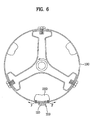
- FIG. 6 is a sectional view illustrating a drum of a drum washing machine according to the first embodiment of the present invention;
- FIG. 7 is a sectional view illustrating a first example of a reinforcing device of FIG. 6;
- FIG. 8 is a sectional view illustrating a fitting member constituting the reinforcing device of FIG. 6;
- FIG. 9 is a sectional view illustrating another fitting member constituting the reinforcing device of FIG. 6;
- FIG. 10 is a sectional view illustrating a second example of a reinforcing device of FIG. 6;
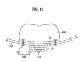
- FIG. 11 is a sectional view illustrating a third example of a reinforcing device of FIG. 6;
- FIG. 12 is a sectional view illustrating a drum of a drum washing machine according to the second embodiment of the present invention;
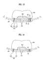
- FIG. 13 is a sectional view illustrating a first example of a reinforcing device of FIG. 12;
- FIG. 14 is a sectional view illustrating a second example of a reinforcing device of FIG. 12;
- FIG. 15 is a sectional view illustrating a third example of a reinforcing device of FIG. 12; and
- FIG. 16 is a sectional view illustrating a portion of a drum of a drum washing machine according to the third embodiment of the present invention.
- The following will explain, with reference to the above-described drawings, preferred embodiments of the present invention, in which like characters represent like elements. The particulars shown herein are by way of illustrative example of the embodiments of the invention only and are presented in the cause of providing what is believed to be the most useful and readily understood description of the principles and conceptual versions of the present invention. In this regard, no attempt is made to show structural details of the invention in more detail than is necessary for the fundamental understanding of the present invention, the description taken with the drawings making apparent to those skilled in the art how the several forms of the present invention may be embodied in practice.
- A drum of a drum washing machine according to the first embodiment of the present invention will be described with reference to FIG. 6.
- The drum includes a
body 100 having a seamingportion 110 whose both circumferential ends are connected with each other, and a reinforcingdevice 310 fixed onto the seaming (or seam)portion 110 to disperse tension F in a circumferential direction, which acts on the seaming portion. - The seaming
portion 110 is provided in such a manner that the circumferential ends of thebody 100 are connected to each other when they are bent. The seamingportion 110 may be bent in various shapes without being limited to the configuration of FIG. 6. For example, both circumferential ends may be connected with each other such that they are bent twice or more. - The seaming
portion 110 is protruded at the outer side of thebody 100. - In this case, a
lift 200 is preferably arranged to correspond to an inner side of the seamingportion 110. Thelift 200 is to prevent the laundry from being damaged by shag (a snag) generated when the laundry contacts the seamingportion 110. Thelift 200 has a filled inner portion or a hollow inner portion. - The reinforcing
device 310 is provided to surround the seamingportion 110. Various examples of the reinforcingdevice 310 will be described below. - The first example of the reinforcing means 310 will be described in more detail with reference to FIG. 7.
- The reinforcing
device 310 includes reinforcingpanels portion 110, and afitting member 313 provided at both circumferential ends of the reinforcing panels to disperse tension F circumferentially acting on thebody 100 between the reinforcingpanels portion 110. - The reinforcing
panels portion 110. Preferably, the reinforcingpanels portion 110. This is to allow the reinforcingpanels portion 110. In addition, both circumferential sides of the reinforcingpanels - At this time, the
lift 200 is preferably arranged to cover the reinforcingpanel 312. This is to prevent the laundry from being damaged by the reinforcingpanel 312 arranged on the inner surface of the seamingportion 110. - Preferably, the reinforcing
panels body 100 are made of the same material as each other in view of elasticity and contractile force, so that tension of thebody 100 may be dispersed more efficiently. However, it is to be understood that the reinforcingpanels body 100 in view of elasticity and contractile force. - Furthermore, the
fitting member 313 is fitted into thelift 200 through the reinforcingpanels body 100. A plurality offitting members 313 are arranged at both circumferential sides of the seamingportion 110 along a length direction of the seaming portion. - As an example of the
fitting member 313, a nut is fixed to thelift 200 and then a bolt is fitted into the nut. In this case, no separate fitting member is required to fix thelift 200 to thebody 100 of the drum. Also, it is possible to prevent thefitting member 313 from being protruded toward the inner surface of thebody 100. - Although not shown, it is to be understood that a bolt may directly be fixed to the lift. Similarly other types of fitting members may be used.
- Referring to FIG. 8, another
fitting member 315 constituting the reinforcing device will be described. - The
fitting member 315 pass through the reinforcingpanels body 100 but is not fitted to thelift 200. Agroove 201 is formed at one side of thelift 200 toward the body to receive one end of thefitting member 313. Bolt and nut are used as thefitting member 315. - In case of such reinforcing
panels body 100 is transferred to thelift 200. - Referring to FIG. 9, another
fitting member 316 constituting the reinforcing device will be described. - A rivet is used as the
fitting member 316. Since thefitting member 316 of FIG. 9 is substantially equal to that of FIG. 8 except that the rivet is used as the fitting member, its description will be omitted. It is to be understood that the rivet may be used in a structure that the groove of FIG. 8 is formed. - In addition, the rivet passes through the reinforcing
panels body 100 but is not fitted into thelift 200. - In case of such reinforcing
panels body 100 is transferred to thelift 200. - The operation of the drum according to the first embodiment of the present invention will now be described.
- Tension F of the drum acts on the reinforcing
device 310 along both circumferential sides. Particularly, great tension acts on the reinforcingdevice 310 during a drying cycle in which the drum is rotated at high speed. - At this time, tension F is dispersed into the reinforcing
panels portion 110 and/or thelift 200 by thefitting members - For example, if the
fitting member 313 is fitted into the reinforcingpanels body 100 and thelift 200 as shown in FIG. 7, tension F is dispersed into the reinforcingpanels body 100 and the lift 200 (F=F1+F2+F3+F4). - In addition, if the
fitting members panels body 100 as shown in FIG. 8 and FIG. 9, tension F is dispersed into the reinforcingpanels - Finally, since tension is dispersed by the reinforcing
device 310, only some tension F2 acts on the seamingportion 110 as shown in FIG. 7 to FIG. 9. - Meanwhile, since the outer reinforcing
panel 311 surrounds the outer surface of the seamingportion 110 and the inner reinforcingpanel 312 surrounds the inner surface of the seamingportion 110, it is possible to prevent the seaming portion from being unfolded. - Further, since the inner reinforcing
panel 312 is almost parallel to a direction of tension of thebody 100, the inner reinforcingpanel 312 can absorb tension of thebody 100 more than the outer reinforcingpanel 311 and the seamingportion 110. - Further, since the
fitting members panel 312 are not exposed to the inner portion of the drum due to thelift 200, it is possible to prevent the laundry from contacting thefitting members panel 312. Therefore, the laundry can be prevented from being damaged. - A second example of the reinforcing device will be described with reference to FIG. 10.
- In the second example, the reinforcing
panel 321 is arranged on the outer surface of the seamingportion 110. Therefore, the reinforcing means 320 is comprised of an outer reinforcingpanel 321 and afitting member 323. - Since the reinforcing
panel 321 surrounds the outer surface of the seamingportion 110 and thelift 200 surrounds the inner surface of the seamingportion 110, it is possible to prevent the seamingportion 110 from being unfolded. - Further, since the reinforcing
device 320 is fixed to the outer side of the drum in a state that thelift 200 is fixed, assembly time can remarkably be reduced. As described above, thefitting member 323 may fit or secure the reinforcingpanel 321, thebody 100 and thelift 200 or may fit or secure the reinforcingpanel 321 and thebody 100 only. - Tension F of the drum is dispersed into the outer reinforcing
panel 321 and the seaming portion 110 (F=F1+F2). The outer reinforcingpanel 321 not only disperses tension but also prevents the seamingportion 110 from being unfolded. - A third example of the reinforcing device will be described with reference to FIG. 11.
- In the third example, the reinforcing
panel 332 is arranged on the inner surface of the seamingportion 110. Therefore, the reinforcingdevice 330 is comprised of an inner reinforcingpanel 332 and afitting member 333. - Since the inner reinforcing
panel 332 is substantially parallel to a direction of tension F of thebody 100, the inner reinforcingpanel 332 can absorb tension of thebody 100 more than the seamingportion 110. In this respect, the third example of the reinforcing device is more efficient than the second example in absorbing tension. - Further, the
fitting member 333 may fit or secure the reinforcingpanel 332, thebody 100 and thelift 200 or may fit or secure the reinforcingpanel 332 and thebody 100 only. - Tension F of the drum is dispersed into the inner reinforcing
panel 332 and the seaming portion 110 (F=F1+F2). - A drum of a drum washing machine according to the second embodiment of the present invention will be described with reference to FIG. 12.
- The drum includes a
body 100 having a seamingportion 110 whose both circumferential ends are connected with each other, the seamingportion 110 being internally protruded, a reinforcingdevice 410 is fixed onto the seamingportion 110 to disperse tension F in a circumferential direction, which acts on the seamingportion 110, and alift 200 receives the seamingportion 110 therein. - The
lift 200 is provided with a receivinggroove 210 to receive the seamingportion 110. It is to be understood that no separate receiving groove is required if the lift has a hollow structure. - The reinforcing
device 410 includes reinforcingpanels portion 110, and a fitting member 413 (see FIG. 13) to fit or secure the reinforcing panels to thebody 100 to disperse tension F, which acts on the body in a circumferential direction, is provided between the reinforcing panels and the seaming portion. - Various examples of the reinforcing
device 410 will be described below. - A first example of the reinforcing
device 410 will be described with reference to FIG. 13. - The reinforcing
panels portion 110. In other words, the inner reinforcingpanel 412 surrounds the inner surface of the seamingportion 110 while the outer reinforcingpanel 411 surrounds the outer surface of the seamingportion 110. The protruded portion of the inner reinforcingpanel 412 contacts the receivinggroove 210 of thelift 200. Therefore, thelift 200 not only prevents the seamingportion 110 and the inner reinforcingpanel 412 from being directly contacted with the laundry but also prevents the seaming portion from being unfolded. - Since the
fitting member 413 is the same as that of the drum according to the first embodiment, its description will be omitted. - A second example of the reinforcing device will be described with reference to FIG. 14.
- A reinforcing
panel 421 is arranged to surround the outer surface of the seamingportion 110. In this case, since the seamingportion 110 contacts the receivinggroove 210 of thelift 200, thelift 200 not only prevents the seamingportion 110 from being unfolded but also prevents the seamingportion 110 from being contacted with the laundry. - A
fitting member 423 is fitted into thelift 200 through the reinforcingpanel 421 and thebody 100. Also, thefitting member 423 may not be fitted into thelift 200. - A third example of the reinforcing device will be described with reference to FIG. 15.
- A reinforcing
panel 432 is arranged to surround the inner surface of the seamingportion 110. In this case, the seamingportion 110 and the protruded portion of the reinforcingpanel 432 are received in the receivinggroove 210 of thelift 200. - A
fitting member 433 is fitted into thelift 200 through the reinforcingpanel 432 and thebody 100. - A drum of a drum washing machine according to the third embodiment of the present invention will be described with reference to FIG. 16.
- The drum includes a
body 100 having a seamingportion 110 whose both circumferential ends are connected with each other, the seaming portion being internally protruded, and alift 200 receiving the seamingportion 110 therein. - Preferably, the
lift 200 is provided with a receivinggroove 210 to receive the seamingportion 110. - In the third embodiment unlike the first and second embodiments, the
lift 200 can prevent the seamingportion 110 from being unfolded or distorted without a separate reinforcing device. The third embodiment is different from the first and second embodiments in that tension acting on the seamingportion 110 is dispersed into thelift 200 only. - As described above, the drum of the drum washing machine according to the present invention has the following advantages.
- First, in the first and second embodiments, since tension of the body is dispersed by the reinforcing device, tension acting on the seaming portion can remarkably (i.e., significantly) be reduced.
- Second, in the first and second embodiments, since tension acting on the seaming portion is reduced, the drum can be used in the drum washing machine of high speed and large volume.
- Third, in the first, second and third embodiments, since the lift is arranged to cover the seaming portion and the fitting member, it is possible to prevent the laundry from being damaged by the seaming portion and the fitting member.
- Finally, in the third embodiment, it is possible to prevent the seaming portion from being unfolded or distorted without a separate reinforcing means.
- It is noted that the foregoing examples have been provided merely for the purpose of explanation and are in no way to be construed as limiting of the present invention. While the present invention has been described with reference to exemplary embodiments, it is understood that the words which have been used herein are words of description and illustration, rather than words of limitation. The present teachings can be readily applied to other types of apparatuses. Changes may be made, within the purview of the appended claims, as presently stated and as amended, without departing from the scope and spirit of the present invention in its versions. Although the present invention has been described herein with reference to particular structures, materials and embodiments, the present invention is not intended to be limited to the particulars disclosed herein; rather, the present invention extends to all functionally equivalent structures, methods and uses, such as are within the scope of the appended claims. Alternative structures discussed for the purpose of highlighting the invention's advantages do not constitute prior art unless expressly so identified. No one or more features of the present invention are necessary or critical unless otherwise specified.
- Accordingly, a drum washing machine is provided, having a seaming portion of the drum that is prevented from being unfolded or distorted even when the drum is rotated at high speed, by dispersing tension in a circumferential direction, which acts on the seaming portion. The seaming portion is provided with a lift to prevent the laundry from being damaged.
Claims (15)
- A drum of a drum washing machine comprising:a body (100) having a seam portion (110), both circumferential ends of the body being connected with each other at the seam portion (110); anda reinforcing device (310; 320; 330; 410; 420; 430) fixed to the seam portion (110) to disperse, in a circumferential direction, tension acting on the seam portion (110).
- A drum of a drum washing machine comprising:a body (100) having a seam portion (110), both circumferential ends of the body (100) being connected with each other at the seam portion (110), the seam portion (110) protruding externally of the body (100);a reinforcing device (310; 320; 330) fixed onto the seam portion (110) to disperse tension, which acts on the seam portion (110), in a circumferential direction; anda lift (200) arranged in correspondence to the seam portion (110).
- A drum of a drum washing machine comprising:a body (100) having a seam portion (110), both circumferential ends of the body (100) being connected with each other at the seam portion (110), the seam portion (110) protruding internally of the body;a reinforcing device (410; 420; 430) fixed onto the seam portion (110) to disperse tension, which acts on the seaming portion (110), in a circumferential direction; anda lift (200) receiving the seam portion (110) therein.
- The drum according to claim 3, wherein the lift (200) is provided with a receiving groove (210) to receive the seam portion (110).
- The drum according to one of claims 1 to 4, wherein the reinforcing device includes:reinforcing panels (311, 312; 321; 332; 411, 412; 421; 432) positioned on the seam portion (110); andfitting members (313; 315; 316; 323; 413; 423; 433) fitting the reinforcing panels (311, 312; 321; 332; 411, 412; 421; 432) with the body to (100) disperse the tension into the reinforcing panels (311, 312; 321; 332; 411, 412; 421; 432) and the seaming portion (110).
- The drum according to claim 5, wherein the fitting members (313; 315; 316; 323; 413; 423; 433) are positioned at both circumferential sides around the seam portion (110).
- The drum according to claim 5 or 6, wherein the reinforcing panels (311, 312; 321; 332; 411, 412; 421; 432) are positioned on outer and inner surfaces of the seam portion (110).
- The drum according to claim 5 or 6, wherein the reinforcing panels (311, 312; 321; 332; 411, 412; 421; 432) are positioned on either an inner surface or an outer surface of the seam portion (110).
- The drum according to one of claims 5 to 8, wherein a lift (200) is arranged in correspondence to the seam portion (110) of the body (100).
- The drum according to claim 9, wherein the fitting members (313; 315; 316; 323; 413; 423; 433) are fitted into the lift (200) through the body (100) and the reinforcing panels (311, 312; 321; 332; 411, 412; 421; 432) to disperse the tension into the body (100), the reinforcing panels (311, 312; 321; 332; 411, 412; 421; 432) and the lift (200).
- The drum according to claim 9 or 10, wherein the fitting members (313; 315; 316; 323; 413; 423; 433) pass through the body (100) and the reinforcing panels (311, 312; 321; 332; 411, 412; 421; 432) to disperse the tension into the body (100) and the reinforcing panels (311, 312; 321; 332; 411, 412; 421; 432), without being fitted into the lift (200).
- The drum according to claim 11, wherein the lift (200) is provided with a groove (201) to receive one end of each of the fitting members (313; 315; 316; 323; 413; 423; 433).
- The drum according to one of claims 5 to 12, wherein the fitting members (313; 315; 316; 323; 413; 423; 433) are bolts or rivets.
- A drum of a drum washing machine comprising:a body (100) having a seam portion (110), both circumferential ends of the body (100) being connected with each other at the seam portion (110), the seam portion (110) being configured to protrude internally of the body (100); anda lift (200) receiving the seam portion therein.
- A washing machine having a drum according to one of claims 1 to 14.
Applications Claiming Priority (1)
| Application Number | Priority Date | Filing Date | Title |
|---|---|---|---|
| KR1020050001713A KR100662447B1 (en) | 2005-01-07 | 2005-01-07 | Drum of drum washing machine |
Publications (1)
| Publication Number | Publication Date |
|---|---|
| EP1679400A1 true EP1679400A1 (en) | 2006-07-12 |
Family
ID=36102615
Family Applications (1)
| Application Number | Title | Priority Date | Filing Date |
|---|---|---|---|
| EP05015672A Withdrawn EP1679400A1 (en) | 2005-01-07 | 2005-07-19 | Drum of drum type washing machine |
Country Status (5)
| Country | Link |
|---|---|
| US (1) | US20060150688A1 (en) |
| EP (1) | EP1679400A1 (en) |
| JP (1) | JP2006187609A (en) |
| KR (1) | KR100662447B1 (en) |
| CN (1) | CN1800483A (en) |
Cited By (4)
| Publication number | Priority date | Publication date | Assignee | Title |
|---|---|---|---|---|
| WO2009109527A1 (en) * | 2008-03-03 | 2009-09-11 | BSH Bosch und Siemens Hausgeräte GmbH | Wash drum for a washing machine and method for producing such a wash drum |
| US7836607B2 (en) * | 2004-06-05 | 2010-11-23 | Lg Electronics Inc. | Drum of laundry dryer |
| WO2011067287A1 (en) * | 2009-12-03 | 2011-06-09 | BSH Bosch und Siemens Hausgeräte GmbH | Laundry processing drum and laundry processing apparatus using the same |
| WO2015078522A1 (en) * | 2013-11-29 | 2015-06-04 | Arcelik Anonim Sirketi | Laundry treatment appliance comprising a washing receptacle having laundry protection structure |
Families Citing this family (9)
| Publication number | Priority date | Publication date | Assignee | Title |
|---|---|---|---|---|
| KR100725742B1 (en) * | 2006-01-11 | 2007-06-08 | 삼성전자주식회사 | Drum Washing Machine |
| EP1994214B1 (en) * | 2006-03-16 | 2014-07-23 | LG Electronics, Inc. | Top-loading drum type washing machine |
| JP5411314B2 (en) * | 2012-05-14 | 2014-02-12 | 日立アプライアンス株式会社 | Washing machine and washing and drying machine |
| CN102912584B (en) * | 2012-06-06 | 2017-09-29 | 青岛海尔洗衣机有限公司 | A kind of three dynamical washing machines |
| USD722212S1 (en) * | 2012-11-05 | 2015-02-03 | Samsung Electronics Co., Ltd. | Drum for washing machine |
| USD720902S1 (en) * | 2012-11-26 | 2015-01-06 | Samsung Electronics Co., Ltd. | Drum for washing machine |
| USD748356S1 (en) * | 2013-07-16 | 2016-01-26 | Whirlpool Corporation | Container for a clothes washing machine |
| USD761501S1 (en) * | 2013-09-27 | 2016-07-12 | Whirlpool Corporation | Container for clothes washing machine |
| KR101646315B1 (en) * | 2013-12-20 | 2016-08-05 | 동부대우전자 주식회사 | Washing machine |
Citations (6)
| Publication number | Priority date | Publication date | Assignee | Title |
|---|---|---|---|---|
| CH32335A (en) * | 1904-12-12 | 1905-07-15 | Emil Neher Fa | Airtight and liquid-tight seam connections made without soldering for metal sheets used to produce vessels |
| DE1936017U (en) * | 1965-08-31 | 1966-04-07 | Constructa Werke G M B H | WASHING MACHINE DRUM. |
| DE3023234A1 (en) * | 1980-06-21 | 1982-01-07 | Miele & Cie GmbH & Co, 4830 Gütersloh | Perforated drum for washing machines, etc. - has cylindrical wall with comb joint secured by rod through centre |
| DE10006975A1 (en) * | 2000-02-16 | 2001-08-30 | Bsh Bosch Siemens Hausgeraete | Washing drum for a washing machine |
| DE10258786A1 (en) * | 2001-12-21 | 2003-07-24 | Bsh Bosch Siemens Hausgeraete | Clothes-washing drum, for a washing machine, uses a high number of revolutions to drain off wet washing with a rotating basket shell with jointed lapped joints and meshing tabs. |
| US20040129036A1 (en) * | 2002-12-17 | 2004-07-08 | Uwe Ratfisch | Laundry drum for a drum-type washing machine |
Family Cites Families (11)
| Publication number | Priority date | Publication date | Assignee | Title |
|---|---|---|---|---|
| US129036A (en) * | 1872-07-16 | Improvement in glass molds and presses | ||
| US1977408A (en) * | 1931-08-01 | 1934-10-16 | Troy Laundry Machinery Co Inc | Lock construction for washing machine cylinders |
| US1969570A (en) * | 1932-11-03 | 1934-08-07 | American Laundry Mach Co | Rotary cylinder structure |
| US2062030A (en) * | 1934-05-31 | 1936-11-24 | American Laundry Mach Co | Rotary cylinder construction |
| DE3914475A1 (en) | 1989-05-02 | 1990-11-08 | Bosch Siemens Hausgeraete | WASHING MACHINE DRUM |
| JP3126555B2 (en) * | 1993-08-10 | 2001-01-22 | 株式会社東芝 | Washing machine dehydration tub |
| KR970062437U (en) * | 1996-05-30 | 1997-12-10 | Tumbler of washing machine | |
| KR100207085B1 (en) * | 1996-05-30 | 1999-07-15 | 윤종용 | Tumbler of washing machine |
| JP3437729B2 (en) | 1996-11-29 | 2003-08-18 | 株式会社東芝 | Washing machine tub |
| KR100457579B1 (en) * | 2002-11-28 | 2004-11-18 | 엘지전자 주식회사 | drum of drum typed washer |
| KR100539556B1 (en) * | 2003-12-19 | 2005-12-29 | 엘지전자 주식회사 | seaming structure in the drum type washing machine |
-
2005
- 2005-01-07 KR KR1020050001713A patent/KR100662447B1/en not_active Expired - Fee Related
- 2005-07-19 EP EP05015672A patent/EP1679400A1/en not_active Withdrawn
- 2005-07-20 US US11/184,898 patent/US20060150688A1/en not_active Abandoned
- 2005-07-20 CN CNA2005100847860A patent/CN1800483A/en active Pending
- 2005-12-22 JP JP2005370423A patent/JP2006187609A/en not_active Withdrawn
Patent Citations (6)
| Publication number | Priority date | Publication date | Assignee | Title |
|---|---|---|---|---|
| CH32335A (en) * | 1904-12-12 | 1905-07-15 | Emil Neher Fa | Airtight and liquid-tight seam connections made without soldering for metal sheets used to produce vessels |
| DE1936017U (en) * | 1965-08-31 | 1966-04-07 | Constructa Werke G M B H | WASHING MACHINE DRUM. |
| DE3023234A1 (en) * | 1980-06-21 | 1982-01-07 | Miele & Cie GmbH & Co, 4830 Gütersloh | Perforated drum for washing machines, etc. - has cylindrical wall with comb joint secured by rod through centre |
| DE10006975A1 (en) * | 2000-02-16 | 2001-08-30 | Bsh Bosch Siemens Hausgeraete | Washing drum for a washing machine |
| DE10258786A1 (en) * | 2001-12-21 | 2003-07-24 | Bsh Bosch Siemens Hausgeraete | Clothes-washing drum, for a washing machine, uses a high number of revolutions to drain off wet washing with a rotating basket shell with jointed lapped joints and meshing tabs. |
| US20040129036A1 (en) * | 2002-12-17 | 2004-07-08 | Uwe Ratfisch | Laundry drum for a drum-type washing machine |
Cited By (5)
| Publication number | Priority date | Publication date | Assignee | Title |
|---|---|---|---|---|
| US7836607B2 (en) * | 2004-06-05 | 2010-11-23 | Lg Electronics Inc. | Drum of laundry dryer |
| WO2009109527A1 (en) * | 2008-03-03 | 2009-09-11 | BSH Bosch und Siemens Hausgeräte GmbH | Wash drum for a washing machine and method for producing such a wash drum |
| WO2011067287A1 (en) * | 2009-12-03 | 2011-06-09 | BSH Bosch und Siemens Hausgeräte GmbH | Laundry processing drum and laundry processing apparatus using the same |
| EA021319B1 (en) * | 2009-12-03 | 2015-05-29 | Бсх Бош Унд Сименс Хаусгерете Гмбх | Laundry processing drum for laundry processing apparatus |
| WO2015078522A1 (en) * | 2013-11-29 | 2015-06-04 | Arcelik Anonim Sirketi | Laundry treatment appliance comprising a washing receptacle having laundry protection structure |
Also Published As
| Publication number | Publication date |
|---|---|
| JP2006187609A (en) | 2006-07-20 |
| KR20060081226A (en) | 2006-07-12 |
| CN1800483A (en) | 2006-07-12 |
| KR100662447B1 (en) | 2007-01-02 |
| US20060150688A1 (en) | 2006-07-13 |
Similar Documents
| Publication | Publication Date | Title |
|---|---|---|
| EP1679400A1 (en) | Drum of drum type washing machine | |
| US20070214630A1 (en) | Method for manufacturing drum and washing machine using the drum | |
| US8256248B2 (en) | Rotating tub body and drum-type washing machine having the same | |
| US11913157B2 (en) | Laundry treating apparatus | |
| US5802886A (en) | Spin basket for a washing machine | |
| EP1479811A1 (en) | Damper for washing machine | |
| CN104631043A (en) | Suspension for washing machine and washing machine with the same | |
| EP3715522B1 (en) | Washing drum for a laundry washing machine and laundry washing machine equipped with such drum | |
| US20050257577A1 (en) | Washing machine and method for assembling the same | |
| WO2005049909A1 (en) | A drum with stiffening corrugations along the seam | |
| KR100539556B1 (en) | seaming structure in the drum type washing machine | |
| KR20060005825A (en) | Drum of washing machine | |
| KR100987434B1 (en) | Tub for washing machine | |
| KR20040103447A (en) | Drum Type Washing Machine | |
| JP6684368B2 (en) | Washing and dehydration tub and washing machine | |
| JP3126555B2 (en) | Washing machine dehydration tub | |
| US6029480A (en) | Washing machine with improved anchoring means for the washing assembly | |
| KR20030005572A (en) | Case structure of washing machine | |
| EP0896083A1 (en) | Improved elastic suspension means for the washing assembly of a washing machine | |
| KR100913081B1 (en) | Tub assembly of drum washing machine and tub manufacturing method | |
| KR20070064022A (en) | Damper structure of drum washing machine | |
| KR100229310B1 (en) | Washing machine | |
| WO2020076165A1 (en) | Laundry washing machine drum containment | |
| KR19980057689U (en) | After-sales cover assembly structure of washing machine | |
| KR950023787A (en) | Dehydrating tank structure for washing and washing of automatic washing machine |
Legal Events
| Date | Code | Title | Description |
|---|---|---|---|
| PUAI | Public reference made under article 153(3) epc to a published international application that has entered the european phase |
Free format text: ORIGINAL CODE: 0009012 |
|
| 17P | Request for examination filed |
Effective date: 20050719 |
|
| AK | Designated contracting states |
Kind code of ref document: A1 Designated state(s): AT BE BG CH CY CZ DE DK EE ES FI FR GB GR HU IE IS IT LI LT LU LV MC NL PL PT RO SE SI SK TR |
|
| AX | Request for extension of the european patent |
Extension state: AL BA HR MK YU |
|
| 17Q | First examination report despatched |
Effective date: 20061005 |
|
| AKX | Designation fees paid |
Designated state(s): DE ES GB IT |
|
| 17Q | First examination report despatched |
Effective date: 20061005 |
|
| GRAP | Despatch of communication of intention to grant a patent |
Free format text: ORIGINAL CODE: EPIDOSNIGR1 |
|
| STAA | Information on the status of an ep patent application or granted ep patent |
Free format text: STATUS: THE APPLICATION IS DEEMED TO BE WITHDRAWN |
|
| 18D | Application deemed to be withdrawn |
Effective date: 20090911 |