EP1679244A1 - Steering column rake adjustment device - Google Patents
Steering column rake adjustment device Download PDFInfo
- Publication number
- EP1679244A1 EP1679244A1 EP05077980A EP05077980A EP1679244A1 EP 1679244 A1 EP1679244 A1 EP 1679244A1 EP 05077980 A EP05077980 A EP 05077980A EP 05077980 A EP05077980 A EP 05077980A EP 1679244 A1 EP1679244 A1 EP 1679244A1
- Authority
- EP
- European Patent Office
- Prior art keywords
- steering column
- lock
- column assembly
- fulcrum
- column member
- Prior art date
- Legal status (The legal status is an assumption and is not a legal conclusion. Google has not performed a legal analysis and makes no representation as to the accuracy of the status listed.)
- Granted
Links
Images

Classifications
-
- B—PERFORMING OPERATIONS; TRANSPORTING
- B62—LAND VEHICLES FOR TRAVELLING OTHERWISE THAN ON RAILS
- B62D—MOTOR VEHICLES; TRAILERS
- B62D1/00—Steering controls, i.e. means for initiating a change of direction of the vehicle
- B62D1/02—Steering controls, i.e. means for initiating a change of direction of the vehicle vehicle-mounted
- B62D1/16—Steering columns
- B62D1/18—Steering columns yieldable or adjustable, e.g. tiltable
- B62D1/184—Mechanisms for locking columns at selected positions
Definitions
- the invention relates to steering column assembly for a vehicle and more particularly to a steering column assembly moveable in raking adjustment between a plurality of rake positions and having a lock to fix the steering column assembly at any one of the plurality of rake positions.
- a steering column assembly 10 of the prior art is shown in Figure 1.
- the steering column assembly 10 includes a steering column member 14 rotatable about a first pivoting axis 16 in raking adjustment between a plurality of rake positions.
- a lock 26 fixes the steering column assembly 10 at any one of the plurality of rake positions.
- the lock 26 includes a handle 32 moveable along an arcuate path 34 about an axis 36.
- the handle 32 rotates a shaft (not visible) aligned with the axis 36 to move mating cam members (not visible).
- the cam members cooperate to urge each other apart, creating compressive forces between portions of the steering column assembly 10 and the lock 26.
- the invention provides a steering column assembly having a steering column member for first pivotal movement about a first pivoting axis.
- the steering column assembly also includes a lever supported for second pivotal movement about a fulcrum.
- the lever includes a first end pivotally attached to the steering column member and a second end on an opposite side of the fulcrum relative to the first end.
- the steering column assembly also includes a lock operable to apply a locking force to selectively lock the second end.
- the advantages of the exemplary embodiment of the invention include reduced force required by the operator of the vehicle, reduced forced required of the locking mechanism, and a reduction in the size of the lock if desired.
- the invention provides a steering column assembly 12 having a steering column member 114 for first pivotal movement about a first pivoting axis 116.
- the steering column assembly 12 also includes a lever 18 supported for second pivotal movement about a fulcrum 20.
- the lever 18 includes a first end 22 pivotally attached to the steering column member 114 and a second end 24 on an opposite side of the fulcrum 20 relative to the first end 22.
- the steering column assembly 12 also includes a lock 126 operable to apply a locking force to selectively lock the second end 24.
- the exemplary steering column assembly 12 includes a single steering column member 114.
- the steering column assembly 12 could include a pair of members or jackets disposed in telescoping relation.
- the steering column member 114 at least partially encircles a steering shaft 38.
- a steering wheel 40 is mounted in a vehicle at an end of the steering shaft 38.
- the steering column member 114 is disposed for raking movement, wherein the first pivoting axis 116 is disposed substantially at an opposite end of the steering column member 114 with respect to said steering wheel 40.
- the steering column member 114 is rotatable about the first pivoting axis 116 in raking adjustment between a plurality of rake positions.
- the lock 126 fixes the steering column assembly 10 at any one of the plurality of rake positions.
- the lock 126 of the first exemplary embodiment is a compressive or friction lock and includes a handle 132 moveable along an arcuate path 134 about an axis 136.
- the handle 132 rotates a shaft (not visible) aligned with the axis 136 to move mating cam members (not visible).
- the cam members cooperate to urge each other apart, creating compressive forces between portions of the steering column member 114 and the second end 24 of the lever 18.
- the lock 126 includes a bracket 42 fixed to the vehicle, the bracket 42 and the second end 24 being lockable with respect to one another.
- the cam members cooperate to move closer together, reducing the compressive forces and friction to unlock the second end 24 and the bracket lock 32.
- the lock 126 could be a positive lock.
- the fulcrum 20 of the exemplary embodiment is disposed closer to the first end 22 than the second end 24. As a result, the locking force applied to the second end 24 is multiplied at the first end 22.
- a force of three hundred pounds is required at the lock 26 to maintain the position of the steering column member 14 over forces acting on the steering wheel.
- the distance between the fulcrum 20 and the second end 24 is five times the distance between the fulcrum 20 and the first end 22.
- the first exemplary embodiment of the invention reduces the force required to maintain the position of the steering column member 14 by four-fifths.
- the structure provides several benefits in the first exemplary embodiment of the invention.
- the structure reduces the amount of force that must be generated by the lock 126.
- the lock 126 can be smaller, while maintaining the strength and robustness required in any particular operating environment.
- a second advantage is that the force required of the operator to engage the lock 126 is reduced.
- a third advantage is that the extent of movement of the handle 132 over the path 134 can be reduced, while maintaining the strength and robustness required in any particular operating environment.
- a fourth advantage is that the structure provides flexibility in mounting the lock 126. In other words, the lock 126 can be mounted at any location remote from the steering column member 114. Other advantages may spring from application of the structure of the invention to other operating environments in alternative embodiments of the invention.
- the invention provides a steering column assembly 112 having a steering column member 214 for first pivotal movement about a first pivoting axis 216.
- the steering column assembly 112 also includes a lever 118 supported for second pivotal movement about a fulcrum 120.
- the lever 118 includes a first end 122 pivotally attached to the steering column member 214 and a second end 124 on an opposite side of the fulcrum 120 relative to the first end 122.
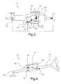
- the steering column assembly 112 also includes a lock 226 operable to apply a locking force to selectively lock the second end 124. This force multiplying relationship set forth above is also demonstrated in the second embodiment of the invention shown in Figure 3.
- Reference character "a” is the distance between the first end 122 of the lever 118 and a point A.
- a force F A acts at point A.
- Reference character “b” is the distance between the first end 122 of the lever 118 and the first pivoting axis 216.
- Reference character “L 1 " is the distance between the fulcrum and the second end 124.
- Reference character “L 2 " is the distance between the fulcrum and the first end 122.
- the invention provides a steering column assembly 212 having a steering column member 314 for first pivotal movement about a first pivoting axis 316.
- the steering column assembly 212 also includes a lever 218 supported for second pivotal movement about a fulcrum 220.
- the lever 218 includes a first end 222 pivotally attached to the steering column member 314 and a second end 224 on an opposite side of the fulcrum 220 relative to the first end 222.
- the steering column assembly 212 also includes a lock 326 operable to apply a locking force to selectively lock the second end 224.
- first and second ends and fulcrum can be varied to enhance the operation of any particular operating environment.
- first end 22 is spaced closer to the first pivoting axis 116 than the second end 24.
- first end 122 is spaced closer to the first pivoting axis 216 than the second end 124.
- first end 222 is spaced further from the first pivoting axis 316 than the second end 224.
- At least one of the first steering column member 114, 214, 314 and the lock 126, 226, 326 includes a slot 28, 128, 30, 130, 230 receiving the respective end 22, 122, 222, 24, 124, 224 of the lever 18, 118, 218.
- the slots 28, 128, 30, 130, 230 are centered on the respective fulcrums 20, 120, 220.
- the respective end 22, 122, 222, 24, 124, 224 is moveable in the slot 28, 128, 30, 130, 230 when the lock 126, 226, 326 is unlocked.
- the first steering column member 114 includes a first slot 28 receiving the first end 22 and the lock 126 includes a second slot 30 receiving the second end 24.
- the first steering column member 214 includes a first slot 128 receiving the first end 122 and the lock 226 includes a second slot 130 receiving the second end 124.
- the lock 226 includes a bracket 142 defining the second slot 130 and encircling the steering column member 214.
- the lever 118 is disposed between the bracket 142 and the steering column member 214.
- the lock 326 includes a second slot 230 receiving the second end 224.
- the first end 222 is linearly fixed and rotatably engaged with respect to the first steering column member 314.
Landscapes
- Engineering & Computer Science (AREA)
- Chemical & Material Sciences (AREA)
- Combustion & Propulsion (AREA)
- Transportation (AREA)
- Mechanical Engineering (AREA)
- Steering Controls (AREA)
- Lock And Its Accessories (AREA)
- Automatic Cycles, And Cycles In General (AREA)
- Steering-Linkage Mechanisms And Four-Wheel Steering (AREA)
Abstract

Description
- The invention relates to steering column assembly for a vehicle and more particularly to a steering column assembly moveable in raking adjustment between a plurality of rake positions and having a lock to fix the steering column assembly at any one of the plurality of rake positions.
- A
steering column assembly 10 of the prior art is shown in Figure 1. Thesteering column assembly 10 includes asteering column member 14 rotatable about afirst pivoting axis 16 in raking adjustment between a plurality of rake positions. Alock 26 fixes thesteering column assembly 10 at any one of the plurality of rake positions. Thelock 26 includes ahandle 32 moveable along anarcuate path 34 about anaxis 36. Thehandle 32 rotates a shaft (not visible) aligned with theaxis 36 to move mating cam members (not visible). When thehandle 32 rotates in a first direction along thepath 32, the cam members cooperate to urge each other apart, creating compressive forces between portions of thesteering column assembly 10 and thelock 26. These forces increase friction and lock thesteering column assembly 10 and thelock 26 together. When thehandle 32 rotates in a second direction opposite the first direction along thepath 34, the cam members cooperate to move closer together, reducing the compressive forces and friction to unlock thesteering column assembly 10 and thelock 26. Examples of these kinds of compressive or friction locks are disclosed in U.S. Pat. Nos. 4,732,050; 5,052,240; and 5,570,610. - The invention provides a steering column assembly having a steering column member for first pivotal movement about a first pivoting axis. The steering column assembly also includes a lever supported for second pivotal movement about a fulcrum. The lever includes a first end pivotally attached to the steering column member and a second end on an opposite side of the fulcrum relative to the first end. The steering column assembly also includes a lock operable to apply a locking force to selectively lock the second end.
- The advantages of the exemplary embodiment of the invention include reduced force required by the operator of the vehicle, reduced forced required of the locking mechanism, and a reduction in the size of the lock if desired.
- Other advantages of the present invention will be readily appreciated as the same becomes better understood by reference to the following detailed description when considered in connection with the accompanying drawings wherein:
- Figure 1 is schematic view of a steering column assembly disclosed in the prior art;
- Figure 2 is schematic view of a steering column assembly according to a first exemplary embodiment of the invention;
- Figure 3 is schematic view of a steering column assembly according to a second exemplary embodiment of the invention; and
- Figure 4 is schematic view of a steering column assembly according to a third exemplary embodiment of the invention.
- A plurality of different embodiments of the invention are shown in the Figures of the application. Similar features are shown in the various embodiments of the invention. Similar features have been numbered with a common two-digit reference numeral and have been differentiated by a third digit placed before the two common digits. Similar features are structured similarly, operate similarly, and/or have the same function unless otherwise indicated by the drawings or this specification. Furthermore, particular features of one embodiment can replace corresponding features in another embodiment unless otherwise indicated by the drawings or this specification.
- In a first embodiment of the invention, show in Figure 2, the invention provides a
steering column assembly 12 having asteering column member 114 for first pivotal movement about afirst pivoting axis 116. Thesteering column assembly 12 also includes alever 18 supported for second pivotal movement about afulcrum 20. Thelever 18 includes afirst end 22 pivotally attached to thesteering column member 114 and asecond end 24 on an opposite side of thefulcrum 20 relative to thefirst end 22. Thesteering column assembly 12 also includes alock 126 operable to apply a locking force to selectively lock thesecond end 24. - The exemplary
steering column assembly 12 includes a singlesteering column member 114. However, in alternative embodiments of the invention, thesteering column assembly 12 could include a pair of members or jackets disposed in telescoping relation. Thesteering column member 114 at least partially encircles asteering shaft 38. Asteering wheel 40 is mounted in a vehicle at an end of thesteering shaft 38. Thesteering column member 114 is disposed for raking movement, wherein thefirst pivoting axis 116 is disposed substantially at an opposite end of thesteering column member 114 with respect to saidsteering wheel 40. - The
steering column member 114 is rotatable about thefirst pivoting axis 116 in raking adjustment between a plurality of rake positions. Thelock 126 fixes thesteering column assembly 10 at any one of the plurality of rake positions. Thelock 126 of the first exemplary embodiment is a compressive or friction lock and includes ahandle 132 moveable along anarcuate path 134 about anaxis 136. Thehandle 132 rotates a shaft (not visible) aligned with theaxis 136 to move mating cam members (not visible). When thehandle 132 rotates in a first direction along thepath 132, the cam members cooperate to urge each other apart, creating compressive forces between portions of thesteering column member 114 and thesecond end 24 of thelever 18. These forces increase friction and lock thesecond end 24 and thelock 126 together. For example, thelock 126 includes abracket 42 fixed to the vehicle, thebracket 42 and thesecond end 24 being lockable with respect to one another. When thehandle 32 rotates in a second direction opposite the first direction along thepath 32, the cam members cooperate to move closer together, reducing the compressive forces and friction to unlock thesecond end 24 and the bracket lock 32. In alternative embodiments of the invention, thelock 126 could be a positive lock. - The
fulcrum 20 of the exemplary embodiment is disposed closer to thefirst end 22 than thesecond end 24. As a result, the locking force applied to thesecond end 24 is multiplied at thefirst end 22. For example, in view of Figure 1, assume a force of three hundred pounds is required at thelock 26 to maintain the position of thesteering column member 14 over forces acting on the steering wheel. Also, in view of Figure 2, assume the distance between thefulcrum 20 and thesecond end 24 is five times the distance between thefulcrum 20 and thefirst end 22. The first exemplary embodiment of the invention reduces the force required to maintain the position of thesteering column member 14 by four-fifths. In other words, three hundred pounds of force disposed one unit of measurement from the fulcrum corresponds to sixty pounds of force five units of measurement from the fulcrum. The structure provided by the invention provides several benefits in the first exemplary embodiment of the invention. First, the structure reduces the amount of force that must be generated by thelock 126. Thelock 126 can be smaller, while maintaining the strength and robustness required in any particular operating environment. A second advantage is that the force required of the operator to engage thelock 126 is reduced. A third advantage is that the extent of movement of thehandle 132 over thepath 134 can be reduced, while maintaining the strength and robustness required in any particular operating environment. A fourth advantage is that the structure provides flexibility in mounting thelock 126. In other words, thelock 126 can be mounted at any location remote from thesteering column member 114. Other advantages may spring from application of the structure of the invention to other operating environments in alternative embodiments of the invention. - In a second embodiment of the invention, show in Figure 3, the invention provides a
steering column assembly 112 having asteering column member 214 for first pivotal movement about afirst pivoting axis 216. Thesteering column assembly 112 also includes alever 118 supported for second pivotal movement about afulcrum 120. Thelever 118 includes afirst end 122 pivotally attached to thesteering column member 214 and asecond end 124 on an opposite side of thefulcrum 120 relative to thefirst end 122. Thesteering column assembly 112 also includes alock 226 operable to apply a locking force to selectively lock thesecond end 124.
This force multiplying relationship set forth above is also demonstrated in the second embodiment of the invention shown in Figure 3. Reference character "a" is the distance between thefirst end 122 of thelever 118 and a point A. A force FA acts at point A. Reference character "b" is the distance between thefirst end 122 of thelever 118 and thefirst pivoting axis 216. Reference character "L1" is the distance between the fulcrum and thesecond end 124. Reference character "L2" is the distance between the fulcrum and thefirst end 122. The holding force FB at point B required to maintain the position of asteering column member 214 over force FA acting at point A equals:
- The corresponding holding force FD required at point D equals:

- Since L1 is greater than L2 , FB is greater than FD.
- In a third embodiment of the invention, show in Figure 4, the invention provides a
steering column assembly 212 having asteering column member 314 for first pivotal movement about afirst pivoting axis 316. Thesteering column assembly 212 also includes alever 218 supported for second pivotal movement about afulcrum 220. Thelever 218 includes afirst end 222 pivotally attached to thesteering column member 314 and asecond end 224 on an opposite side of thefulcrum 220 relative to thefirst end 222. Thesteering column assembly 212 also includes alock 326 operable to apply a locking force to selectively lock thesecond end 224. - The relative positions of the first and second ends and fulcrum can be varied to enhance the operation of any particular operating environment. For example, in the first exemplary embodiment of the invention shown in Figure 2, the
first end 22 is spaced closer to thefirst pivoting axis 116 than thesecond end 24. Similarly, in the second exemplary embodiment of the invention shown in Figure 3, thefirst end 122 is spaced closer to thefirst pivoting axis 216 than thesecond end 124. On the other hand, in the third exemplary embodiment of the invention shown in Figure 4, thefirst end 222 is spaced further from thefirst pivoting axis 316 than thesecond end 224. - In the exemplary embodiments of the invention shown in the application, at least one of the first
steering column member lock slot respective end lever slots respective fulcrums respective end slot lock steering column member 114 includes afirst slot 28 receiving thefirst end 22 and thelock 126 includes asecond slot 30 receiving thesecond end 24. Similarly, in the second exemplary embodiment of the invention shown in Figure 3, the firststeering column member 214 includes afirst slot 128 receiving thefirst end 122 and thelock 226 includes asecond slot 130 receiving thesecond end 124. Thelock 226 includes abracket 142 defining thesecond slot 130 and encircling thesteering column member 214. Thelever 118 is disposed between thebracket 142 and thesteering column member 214. In the third exemplary embodiment of the invention shown in Figure 4, thelock 326 includes asecond slot 230 receiving thesecond end 224. Thefirst end 222 is linearly fixed and rotatably engaged with respect to the firststeering column member 314. - While the invention has been described with reference to an exemplary embodiment, it will be understood by those skilled in the art that various changes may be made and equivalents may be substituted for elements thereof without departing from the scope of the invention. In addition, many modifications may be made to adapt a particular situation or material to the teachings of the invention without departing from the essential scope thereof. Therefore, it is intended that the invention not be limited to the particular embodiment disclosed as the best mode contemplated for carrying out this invention, but that the invention will include all embodiments falling within the scope of the appended claims.
Claims (10)
- A steering column assembly (12, 112, 212) comprising:a steering column member (114, 214, 314) for first pivotal movement about a first pivoting axis (116, 216, 316);a lever (18, 118, 218) supported for second pivotal movement about a fulcrum (20, 120, 220) with a first end (22, 122, 222) pivotally attached to said steering column member (114, 214, 314) and a second end (24, 124, 224) on an opposite side of said fulcrum (20, 120, 220) relative to said first end (22, 122, 222); anda lock (126, 226, 326) operable to apply a locking force to selectively lock said second end (24, 124, 224).
- The steering column assembly (12, 112, 212) of claim 1 wherein said fulcrum (20, 120, 220) is disposed closer to said first end (22, 122, 222) than said second end (24, 124, 224) such that said locking force on said second end (24, 124, 224) is multiplied at said first end (22, 122, 222).
- The steering column assembly (12, 112, 212) of claim 1 wherein said steering column member (114, 214, 314) is further defined as being a steering column jacket disposed for raking movement.
- The steering column assembly (12, 112, 212) of claim 1 wherein said lock (126, 226, 326) is a compression lock (126, 226, 326).
- The steering column assembly (212) of claim 1 wherein said second end (224) is spaced closer to said first pivoting axis (316) than said first end (222).
- The steering column assembly (12, 112) of claim 1 wherein said first end (22, 122) is spaced closer to said first pivoting axis (116, 216) than said second end (24, 124).
- The steering column assembly (12, 112, 212) of claim 1 wherein at least one of said first steering column member (114, 214, 314) and said lock (126, 226, 326) includes a slot (28, 128, 30, 130, 230) receiving said respective end (22, 122, 222, 24, 124, 224) of said lever (18, 118, 218), wherein said respective end (22, 122, 222, 24, 124, 224) is moveable in said slot (28, 128, 30, 130, 230) when said lock (126, 226, 326) is unlocked.
- The steering column assembly (12, 112, 212) of claim 7 wherein said first steering column member (114, 214, 314) includes a first slot (28, 128) receiving said first end (22, 122, 222) and said lock (126, 226, 326) includes a second slot (30, 130, 230) receiving said second end (24, 124, 224).
- The steering column assembly (12, 112, 212) of claim 7 wherein said lock (126, 226, 326) includes a second slot (30, 130, 230) receiving said second end (24, 124, 224) and said first end (22, 122, 222) is linearly fixed and rotatably engaged with respect to said first steering column member (114, 214, 314).
- A method of locking a steering column assembly (12, 112, 212) comprising the steps of:pivotally moving a steering column member (114, 214, 314) about a first pivoting axis (116, 216, 316) in first pivotal movement;supporting a lever (18, 118, 218) for second pivotal movement about a fulcrum (20, 120, 220) with a first end (22, 122, 222) pivotally attached to said steering column member (114, 214, 314) and a second end (24, 124, 224) on an opposite side of said fulcrum (20, 120, 220) relative to said first end (22, 122, 222); andapplying a locking force with a lock (126, 226, 326) to selectively lock the second end (24, 124, 224).
Priority Applications (1)
| Application Number | Priority Date | Filing Date | Title |
|---|---|---|---|
| PL05077980T PL1679244T3 (en) | 2005-01-11 | 2005-12-22 | Steering column rake adjustment device |
Applications Claiming Priority (1)
| Application Number | Priority Date | Filing Date | Title |
|---|---|---|---|
| US11/032,925 US7422238B2 (en) | 2005-01-11 | 2005-01-11 | Rake design for steering column rake adjustment |
Publications (2)
| Publication Number | Publication Date |
|---|---|
| EP1679244A1 true EP1679244A1 (en) | 2006-07-12 |
| EP1679244B1 EP1679244B1 (en) | 2009-04-29 |
Family
ID=35892551
Family Applications (1)
| Application Number | Title | Priority Date | Filing Date |
|---|---|---|---|
| EP05077980A Expired - Lifetime EP1679244B1 (en) | 2005-01-11 | 2005-12-22 | Steering column rake adjustment device |
Country Status (5)
| Country | Link |
|---|---|
| US (1) | US7422238B2 (en) |
| EP (1) | EP1679244B1 (en) |
| AT (1) | ATE430079T1 (en) |
| DE (1) | DE602005014194D1 (en) |
| PL (1) | PL1679244T3 (en) |
Cited By (1)
| Publication number | Priority date | Publication date | Assignee | Title |
|---|---|---|---|---|
| EP2121412A4 (en) * | 2007-02-22 | 2012-12-05 | Scania Cv Abp | Steering column for a vehicle |
Families Citing this family (7)
| Publication number | Priority date | Publication date | Assignee | Title |
|---|---|---|---|---|
| US7942446B2 (en) * | 2004-04-30 | 2011-05-17 | Nexteer (Beijing) Technology Co., Ltd. | Horizontal hybrid collapsing steering column |
| JP5125253B2 (en) * | 2007-06-26 | 2013-01-23 | アイシン精機株式会社 | Vehicle steering device |
| US7942076B2 (en) | 2008-02-14 | 2011-05-17 | Nexteer (Beijing) Technology Co., Ltd. | Adjustable steering column assembly |
| GB2566704A (en) * | 2017-09-21 | 2019-03-27 | Ford Global Tech Llc | A steering assembly |
| US11034377B2 (en) * | 2018-07-31 | 2021-06-15 | Steering Solutions Ip Holding Corporation | System and method of automatically stowing and unstowing a steering column assembly |
| JP7004417B2 (en) * | 2018-08-31 | 2022-01-21 | 株式会社クボタ | Traveling vehicle |
| US11292504B2 (en) * | 2019-03-20 | 2022-04-05 | Volvo Car Corporation | Vehicle having multiple driving positions |
Citations (7)
| Publication number | Priority date | Publication date | Assignee | Title |
|---|---|---|---|---|
| US4018101A (en) * | 1975-08-28 | 1977-04-19 | Eaton Corporation | Positioning device for adjustable steering columns |
| US4732050A (en) | 1986-06-06 | 1988-03-22 | Daimler-Benz Aktiengesellschaft | Receiving arrangement for a steering column of a motor vehicle |
| EP0358198A2 (en) * | 1988-09-08 | 1990-03-14 | Koyo Seiko Co., Ltd. | Tilt steering device |
| US5052240A (en) | 1989-03-06 | 1991-10-01 | Mazda Motor Corporation | Structural arrangement for supporting a tilt steering drive |
| EP0599073A1 (en) * | 1992-11-17 | 1994-06-01 | Lemfoerder Metallwaren Ag. | Adjustable steering column for motor vehicles |
| US5570610A (en) | 1995-06-30 | 1996-11-05 | General Motors Corporation | Adjustable steering column |
| DE19545438A1 (en) * | 1995-12-06 | 1997-06-12 | Zahnradfabrik Friedrichshafen | Adjustable steering device |
Family Cites Families (25)
| Publication number | Priority date | Publication date | Assignee | Title |
|---|---|---|---|---|
| JPS6037892Y2 (en) * | 1981-11-12 | 1985-11-12 | アイシン精機株式会社 | Telescopic steering column locking mechanism |
| JPS60144569U (en) * | 1984-03-07 | 1985-09-25 | 日本精工株式会社 | tilt steering device |
| JPH0342373A (en) * | 1989-07-07 | 1991-02-22 | Nippon Seiko Kk | Tilt type steering device |
| JPH03128763A (en) * | 1989-10-13 | 1991-05-31 | Mazda Motor Corp | Automotive steering device |
| JPH0394373U (en) * | 1990-01-19 | 1991-09-26 | ||
| JPH0443572U (en) * | 1990-08-16 | 1992-04-14 | ||
| GB2252085B (en) * | 1991-01-28 | 1994-10-26 | Torrington Co | Apparatus for connecting adjustable reach steering column to impact actuating means. |
| US5222410A (en) * | 1991-01-31 | 1993-06-29 | Fuji Kiko Co., Ltd. | Steering column assembly |
| FR2714651B1 (en) * | 1994-01-06 | 1996-03-15 | Nacam | Energy absorption device for a motor vehicle steering column. |
| US5566585A (en) * | 1994-03-03 | 1996-10-22 | Chrysler Corporation | Tilt steering column locking mechanism |
| US5452624A (en) * | 1994-03-03 | 1995-09-26 | Chrysler Corporation | Tilt steering column locking mechanism |
| US5788277A (en) * | 1995-03-30 | 1998-08-04 | Nsk Ltd. | Tilt type steering apparatus |
| US5743151A (en) * | 1996-08-12 | 1998-04-28 | Chrysler Corporation | Locking mechanism for tilt steering column |
| US5823062A (en) * | 1996-12-12 | 1998-10-20 | Chrysler Corporation | Tilt steering column lock |
| AU2001259199A1 (en) * | 2000-04-27 | 2001-11-07 | Douglas Autotech Corporation | Tilt lever for adjustable steering columns |
| JP3431886B2 (en) * | 2000-07-07 | 2003-07-28 | 株式会社山田製作所 | Steering position adjustment device |
| JP3895566B2 (en) * | 2001-08-07 | 2007-03-22 | 本田技研工業株式会社 | Vehicle steering device |
| GB2382401B (en) * | 2001-11-22 | 2004-01-14 | Nsk Steering Sys Europ Ltd | Clamping mechanism for an adjustable steering column |
| US6637285B2 (en) * | 2001-12-27 | 2003-10-28 | Daimlerchrysler Corporation | Steering column tilt system multiplier |
| KR100465994B1 (en) * | 2002-01-04 | 2005-01-13 | 현대모비스 주식회사 | Tilt device of steering column for vehicle |
| US6591709B1 (en) * | 2002-02-04 | 2003-07-15 | Daimlerchrysler Corporation | Linear tilt mechanism |
| US6851712B2 (en) * | 2003-04-02 | 2005-02-08 | Mando Corporation | Steering tilt column assembly for vehicle |
| KR100503325B1 (en) * | 2003-06-16 | 2005-07-25 | 현대모비스 주식회사 | Tilt steering apparatus for vehicle |
| US6986531B2 (en) * | 2003-07-24 | 2006-01-17 | Delphi Technologies, Inc. | Steering column linkage tilt lever |
| US7093855B2 (en) * | 2003-12-05 | 2006-08-22 | Delphi Technologies, Inc. | Steering column assembly having clamping mechanism |
-
2005
- 2005-01-11 US US11/032,925 patent/US7422238B2/en not_active Expired - Fee Related
- 2005-12-22 EP EP05077980A patent/EP1679244B1/en not_active Expired - Lifetime
- 2005-12-22 AT AT05077980T patent/ATE430079T1/en not_active IP Right Cessation
- 2005-12-22 PL PL05077980T patent/PL1679244T3/en unknown
- 2005-12-22 DE DE602005014194T patent/DE602005014194D1/en not_active Expired - Lifetime
Patent Citations (7)
| Publication number | Priority date | Publication date | Assignee | Title |
|---|---|---|---|---|
| US4018101A (en) * | 1975-08-28 | 1977-04-19 | Eaton Corporation | Positioning device for adjustable steering columns |
| US4732050A (en) | 1986-06-06 | 1988-03-22 | Daimler-Benz Aktiengesellschaft | Receiving arrangement for a steering column of a motor vehicle |
| EP0358198A2 (en) * | 1988-09-08 | 1990-03-14 | Koyo Seiko Co., Ltd. | Tilt steering device |
| US5052240A (en) | 1989-03-06 | 1991-10-01 | Mazda Motor Corporation | Structural arrangement for supporting a tilt steering drive |
| EP0599073A1 (en) * | 1992-11-17 | 1994-06-01 | Lemfoerder Metallwaren Ag. | Adjustable steering column for motor vehicles |
| US5570610A (en) | 1995-06-30 | 1996-11-05 | General Motors Corporation | Adjustable steering column |
| DE19545438A1 (en) * | 1995-12-06 | 1997-06-12 | Zahnradfabrik Friedrichshafen | Adjustable steering device |
Cited By (1)
| Publication number | Priority date | Publication date | Assignee | Title |
|---|---|---|---|---|
| EP2121412A4 (en) * | 2007-02-22 | 2012-12-05 | Scania Cv Abp | Steering column for a vehicle |
Also Published As
| Publication number | Publication date |
|---|---|
| ATE430079T1 (en) | 2009-05-15 |
| EP1679244B1 (en) | 2009-04-29 |
| DE602005014194D1 (en) | 2009-06-10 |
| US7422238B2 (en) | 2008-09-09 |
| US20060151985A1 (en) | 2006-07-13 |
| PL1679244T3 (en) | 2009-08-31 |
Similar Documents
| Publication | Publication Date | Title |
|---|---|---|
| US6829962B2 (en) | Steering column | |
| EP1125820B1 (en) | Steering device for car | |
| EP1679244B1 (en) | Steering column rake adjustment device | |
| US7438320B2 (en) | Steering column for motor vehicle | |
| JPH07257397A (en) | Slidably inclined type steering column support | |
| US6167777B1 (en) | Tiltable steering column lock mechanism | |
| JPH01172032A (en) | Gear change shifter for automobile | |
| CN111169527A (en) | Locking device for an adjustable steering column assembly | |
| EP2402233A2 (en) | Steering Column Apparatus | |
| US7882761B2 (en) | Adjustable steering column assembly with compressive locking mechanism | |
| JPS59500910A (en) | Cylinder locks, especially automobile steering wheel locks | |
| EP1332942B1 (en) | Surface treatment for a locking mechanism | |
| US5025679A (en) | Structure of tiltable steering column for vehicular steering system | |
| US7503234B2 (en) | One lever tilt and telescope mechanism | |
| EP2718779A1 (en) | Operating element that can be actuated by pressure and rotation | |
| US7503235B2 (en) | Pedal assembly | |
| US5339706A (en) | Latchable steering column tilt mechanism | |
| WO2021167447A1 (en) | Lever assist system for a motorcycle | |
| EP1400430A2 (en) | Steering column | |
| US20050066760A1 (en) | Column shifter with impact absorbing structure | |
| US20030094060A1 (en) | Steering column | |
| KR100349250B1 (en) | Return spring for tilting device of automobile steering column | |
| AU4293200A (en) | Adjusting device | |
| DE102017108487A1 (en) | Pedal for a motor vehicle | |
| JPH01182132A (en) | Transmission gear for automobile |
Legal Events
| Date | Code | Title | Description |
|---|---|---|---|
| PUAI | Public reference made under article 153(3) epc to a published international application that has entered the european phase |
Free format text: ORIGINAL CODE: 0009012 |
|
| AK | Designated contracting states |
Kind code of ref document: A1 Designated state(s): AT BE BG CH CY CZ DE DK EE ES FI FR GB GR HU IE IS IT LI LT LU LV MC NL PL PT RO SE SI SK TR |
|
| AX | Request for extension of the european patent |
Extension state: AL BA HR MK YU |
|
| 17P | Request for examination filed |
Effective date: 20070112 |
|
| 17Q | First examination report despatched |
Effective date: 20070221 |
|
| AKX | Designation fees paid |
Designated state(s): AT BE BG CH CY CZ DE DK EE ES FI FR GB GR HU IE IS IT LI LT LU LV MC NL PL PT RO SE SI SK TR |
|
| GRAP | Despatch of communication of intention to grant a patent |
Free format text: ORIGINAL CODE: EPIDOSNIGR1 |
|
| GRAS | Grant fee paid |
Free format text: ORIGINAL CODE: EPIDOSNIGR3 |
|
| GRAA | (expected) grant |
Free format text: ORIGINAL CODE: 0009210 |
|
| AK | Designated contracting states |
Kind code of ref document: B1 Designated state(s): AT BE BG CH CY CZ DE DK EE ES FI FR GB GR HU IE IS IT LI LT LU LV MC NL PL PT RO SE SI SK TR |
|
| REG | Reference to a national code |
Ref country code: GB Ref legal event code: FG4D |
|
| REG | Reference to a national code |
Ref country code: CH Ref legal event code: EP |
|
| REF | Corresponds to: |
Ref document number: 602005014194 Country of ref document: DE Date of ref document: 20090610 Kind code of ref document: P |
|
| REG | Reference to a national code |
Ref country code: IE Ref legal event code: FG4D |
|
| REG | Reference to a national code |
Ref country code: PL Ref legal event code: T3 |
|
| NLV1 | Nl: lapsed or annulled due to failure to fulfill the requirements of art. 29p and 29m of the patents act | ||
| PG25 | Lapsed in a contracting state [announced via postgrant information from national office to epo] |
Ref country code: LT Free format text: LAPSE BECAUSE OF FAILURE TO SUBMIT A TRANSLATION OF THE DESCRIPTION OR TO PAY THE FEE WITHIN THE PRESCRIBED TIME-LIMIT Effective date: 20090429 Ref country code: FI Free format text: LAPSE BECAUSE OF FAILURE TO SUBMIT A TRANSLATION OF THE DESCRIPTION OR TO PAY THE FEE WITHIN THE PRESCRIBED TIME-LIMIT Effective date: 20090429 Ref country code: PT Free format text: LAPSE BECAUSE OF FAILURE TO SUBMIT A TRANSLATION OF THE DESCRIPTION OR TO PAY THE FEE WITHIN THE PRESCRIBED TIME-LIMIT Effective date: 20090829 Ref country code: AT Free format text: LAPSE BECAUSE OF FAILURE TO SUBMIT A TRANSLATION OF THE DESCRIPTION OR TO PAY THE FEE WITHIN THE PRESCRIBED TIME-LIMIT Effective date: 20090429 Ref country code: ES Free format text: LAPSE BECAUSE OF FAILURE TO SUBMIT A TRANSLATION OF THE DESCRIPTION OR TO PAY THE FEE WITHIN THE PRESCRIBED TIME-LIMIT Effective date: 20090809 |
|
| PG25 | Lapsed in a contracting state [announced via postgrant information from national office to epo] |
Ref country code: NL Free format text: LAPSE BECAUSE OF FAILURE TO SUBMIT A TRANSLATION OF THE DESCRIPTION OR TO PAY THE FEE WITHIN THE PRESCRIBED TIME-LIMIT Effective date: 20090429 Ref country code: LV Free format text: LAPSE BECAUSE OF FAILURE TO SUBMIT A TRANSLATION OF THE DESCRIPTION OR TO PAY THE FEE WITHIN THE PRESCRIBED TIME-LIMIT Effective date: 20090429 Ref country code: IS Free format text: LAPSE BECAUSE OF FAILURE TO SUBMIT A TRANSLATION OF THE DESCRIPTION OR TO PAY THE FEE WITHIN THE PRESCRIBED TIME-LIMIT Effective date: 20090829 Ref country code: SI Free format text: LAPSE BECAUSE OF FAILURE TO SUBMIT A TRANSLATION OF THE DESCRIPTION OR TO PAY THE FEE WITHIN THE PRESCRIBED TIME-LIMIT Effective date: 20090429 Ref country code: SE Free format text: LAPSE BECAUSE OF FAILURE TO SUBMIT A TRANSLATION OF THE DESCRIPTION OR TO PAY THE FEE WITHIN THE PRESCRIBED TIME-LIMIT Effective date: 20090729 |
|
| PG25 | Lapsed in a contracting state [announced via postgrant information from national office to epo] |
Ref country code: RO Free format text: LAPSE BECAUSE OF FAILURE TO SUBMIT A TRANSLATION OF THE DESCRIPTION OR TO PAY THE FEE WITHIN THE PRESCRIBED TIME-LIMIT Effective date: 20090429 Ref country code: CZ Free format text: LAPSE BECAUSE OF FAILURE TO SUBMIT A TRANSLATION OF THE DESCRIPTION OR TO PAY THE FEE WITHIN THE PRESCRIBED TIME-LIMIT Effective date: 20090429 Ref country code: EE Free format text: LAPSE BECAUSE OF FAILURE TO SUBMIT A TRANSLATION OF THE DESCRIPTION OR TO PAY THE FEE WITHIN THE PRESCRIBED TIME-LIMIT Effective date: 20090429 Ref country code: DK Free format text: LAPSE BECAUSE OF FAILURE TO SUBMIT A TRANSLATION OF THE DESCRIPTION OR TO PAY THE FEE WITHIN THE PRESCRIBED TIME-LIMIT Effective date: 20090429 |
|
| PG25 | Lapsed in a contracting state [announced via postgrant information from national office to epo] |
Ref country code: SK Free format text: LAPSE BECAUSE OF FAILURE TO SUBMIT A TRANSLATION OF THE DESCRIPTION OR TO PAY THE FEE WITHIN THE PRESCRIBED TIME-LIMIT Effective date: 20090429 Ref country code: BE Free format text: LAPSE BECAUSE OF FAILURE TO SUBMIT A TRANSLATION OF THE DESCRIPTION OR TO PAY THE FEE WITHIN THE PRESCRIBED TIME-LIMIT Effective date: 20090429 |
|
| PGFP | Annual fee paid to national office [announced via postgrant information from national office to epo] |
Ref country code: PL Payment date: 20091118 Year of fee payment: 5 |
|
| PLBE | No opposition filed within time limit |
Free format text: ORIGINAL CODE: 0009261 |
|
| STAA | Information on the status of an ep patent application or granted ep patent |
Free format text: STATUS: NO OPPOSITION FILED WITHIN TIME LIMIT |
|
| PG25 | Lapsed in a contracting state [announced via postgrant information from national office to epo] |
Ref country code: BG Free format text: LAPSE BECAUSE OF FAILURE TO SUBMIT A TRANSLATION OF THE DESCRIPTION OR TO PAY THE FEE WITHIN THE PRESCRIBED TIME-LIMIT Effective date: 20090729 |
|
| 26N | No opposition filed |
Effective date: 20100201 |
|
| PG25 | Lapsed in a contracting state [announced via postgrant information from national office to epo] |
Ref country code: MC Free format text: LAPSE BECAUSE OF NON-PAYMENT OF DUE FEES Effective date: 20100701 |
|
| REG | Reference to a national code |
Ref country code: CH Ref legal event code: PL |
|
| GBPC | Gb: european patent ceased through non-payment of renewal fee |
Effective date: 20091222 |
|
| REG | Reference to a national code |
Ref country code: FR Ref legal event code: ST Effective date: 20100831 |
|
| REG | Reference to a national code |
Ref country code: IE Ref legal event code: MM4A |
|
| PG25 | Lapsed in a contracting state [announced via postgrant information from national office to epo] |
Ref country code: FR Free format text: LAPSE BECAUSE OF NON-PAYMENT OF DUE FEES Effective date: 20091231 Ref country code: GR Free format text: LAPSE BECAUSE OF FAILURE TO SUBMIT A TRANSLATION OF THE DESCRIPTION OR TO PAY THE FEE WITHIN THE PRESCRIBED TIME-LIMIT Effective date: 20090730 Ref country code: IE Free format text: LAPSE BECAUSE OF NON-PAYMENT OF DUE FEES Effective date: 20091222 Ref country code: LI Free format text: LAPSE BECAUSE OF NON-PAYMENT OF DUE FEES Effective date: 20091231 Ref country code: CH Free format text: LAPSE BECAUSE OF NON-PAYMENT OF DUE FEES Effective date: 20091231 |
|
| REG | Reference to a national code |
Ref country code: FR Ref legal event code: TP |
|
| PG25 | Lapsed in a contracting state [announced via postgrant information from national office to epo] |
Ref country code: GB Free format text: LAPSE BECAUSE OF NON-PAYMENT OF DUE FEES Effective date: 20091222 |
|
| PG25 | Lapsed in a contracting state [announced via postgrant information from national office to epo] |
Ref country code: IT Free format text: LAPSE BECAUSE OF NON-PAYMENT OF DUE FEES Effective date: 20091222 |
|
| PG25 | Lapsed in a contracting state [announced via postgrant information from national office to epo] |
Ref country code: LU Free format text: LAPSE BECAUSE OF NON-PAYMENT OF DUE FEES Effective date: 20091222 |
|
| REG | Reference to a national code |
Ref country code: DE Ref legal event code: R081 Ref document number: 602005014194 Country of ref document: DE Owner name: STEERING SOLUTIONS IP HOLDING CORP., SAGINAW, US Free format text: FORMER OWNER: DELPHI TECHNOLOGIES, INC., TROY, MICH., US Effective date: 20110412 Ref country code: DE Ref legal event code: R081 Ref document number: 602005014194 Country of ref document: DE Owner name: GM GLOBAL TECHNOLOGY OPERATIONS LLC (N. D. GES, US Free format text: FORMER OWNER: DELPHI TECHNOLOGIES, INC., TROY, MICH., US Effective date: 20110412 |
|
| PG25 | Lapsed in a contracting state [announced via postgrant information from national office to epo] |
Ref country code: HU Free format text: LAPSE BECAUSE OF FAILURE TO SUBMIT A TRANSLATION OF THE DESCRIPTION OR TO PAY THE FEE WITHIN THE PRESCRIBED TIME-LIMIT Effective date: 20091030 |
|
| PG25 | Lapsed in a contracting state [announced via postgrant information from national office to epo] |
Ref country code: TR Free format text: LAPSE BECAUSE OF FAILURE TO SUBMIT A TRANSLATION OF THE DESCRIPTION OR TO PAY THE FEE WITHIN THE PRESCRIBED TIME-LIMIT Effective date: 20090429 |
|
| PG25 | Lapsed in a contracting state [announced via postgrant information from national office to epo] |
Ref country code: CY Free format text: LAPSE BECAUSE OF FAILURE TO SUBMIT A TRANSLATION OF THE DESCRIPTION OR TO PAY THE FEE WITHIN THE PRESCRIBED TIME-LIMIT Effective date: 20090429 |
|
| PG25 | Lapsed in a contracting state [announced via postgrant information from national office to epo] |
Ref country code: PL Free format text: LAPSE BECAUSE OF NON-PAYMENT OF DUE FEES Effective date: 20101222 |
|
| REG | Reference to a national code |
Ref country code: DE Ref legal event code: R082 Ref document number: 602005014194 Country of ref document: DE Representative=s name: MANITZ, FINSTERWALD & PARTNER GBR, DE |
|
| REG | Reference to a national code |
Ref country code: DE Ref legal event code: R082 Ref document number: 602005014194 Country of ref document: DE Representative=s name: MANITZ, FINSTERWALD & PARTNER GBR, DE Effective date: 20121019 Ref country code: DE Ref legal event code: R081 Ref document number: 602005014194 Country of ref document: DE Owner name: GM GLOBAL TECHNOLOGY OPERATIONS LLC (N. D. GES, US Free format text: FORMER OWNER: GM GLOBAL TECHNOLOGY OPERATIONS, INC., DETROIT, US Effective date: 20121019 Ref country code: DE Ref legal event code: R081 Ref document number: 602005014194 Country of ref document: DE Owner name: STEERING SOLUTIONS IP HOLDING CORP., US Free format text: FORMER OWNER: GM GLOBAL TECHNOLOGY OPERATIONS, INC., DETROIT, US Effective date: 20121019 Ref country code: DE Ref legal event code: R081 Ref document number: 602005014194 Country of ref document: DE Owner name: GM GLOBAL TECHNOLOGY OPERATIONS LLC (N. D. GES, US Free format text: FORMER OWNER: GM GLOBAL TECHNOLOGY OPERATIONS, INC., DETROIT, MICH., US Effective date: 20121019 Ref country code: DE Ref legal event code: R081 Ref document number: 602005014194 Country of ref document: DE Owner name: STEERING SOLUTIONS IP HOLDING CORP., SAGINAW, US Free format text: FORMER OWNER: GM GLOBAL TECHNOLOGY OPERATIONS, INC., DETROIT, MICH., US Effective date: 20121019 |
|
| REG | Reference to a national code |
Ref country code: PL Ref legal event code: LAPE |
|
| REG | Reference to a national code |
Ref country code: DE Ref legal event code: R082 Ref document number: 602005014194 Country of ref document: DE Representative=s name: MANITZ, FINSTERWALD & PARTNER GBR, DE |
|
| PGFP | Annual fee paid to national office [announced via postgrant information from national office to epo] |
Ref country code: DE Payment date: 20121231 Year of fee payment: 8 |
|
| REG | Reference to a national code |
Ref country code: DE Ref legal event code: R081 Ref document number: 602005014194 Country of ref document: DE Owner name: STEERING SOLUTIONS IP HOLDING CORP., US Free format text: FORMER OWNER: GM GLOBAL TECHNOLOGY OPERATIONS LLC (N. D. GES. D. STAATES DELAWARE), DETROIT, US Effective date: 20130313 Ref country code: DE Ref legal event code: R082 Ref document number: 602005014194 Country of ref document: DE Representative=s name: MANITZ, FINSTERWALD & PARTNER GBR, DE Effective date: 20130313 Ref country code: DE Ref legal event code: R081 Ref document number: 602005014194 Country of ref document: DE Owner name: GM GLOBAL TECHNOLOGY OPERATIONS LLC (N. D. GES, US Free format text: FORMER OWNER: GM GLOBAL TECHNOLOGY OPERATIONS LLC (N. D. GES. D. STAATES DELAWARE), DETROIT, US Effective date: 20130313 Ref country code: DE Ref legal event code: R081 Ref document number: 602005014194 Country of ref document: DE Owner name: GM GLOBAL TECHNOLOGY OPERATIONS LLC (N. D. GES, US Free format text: FORMER OWNER: GM GLOBAL TECHNOLOGY OPERATIONS LLC (N. D. GES. D. STAATES DELAWARE), DETROIT, MICH., US Effective date: 20130313 Ref country code: DE Ref legal event code: R081 Ref document number: 602005014194 Country of ref document: DE Owner name: STEERING SOLUTIONS IP HOLDING CORP., SAGINAW, US Free format text: FORMER OWNER: GM GLOBAL TECHNOLOGY OPERATIONS LLC (N. D. GES. D. STAATES DELAWARE), DETROIT, MICH., US Effective date: 20130313 |
|
| REG | Reference to a national code |
Ref country code: DE Ref legal event code: R119 Ref document number: 602005014194 Country of ref document: DE |
|
| REG | Reference to a national code |
Ref country code: DE Ref legal event code: R119 Ref document number: 602005014194 Country of ref document: DE Effective date: 20140701 |
|
| PG25 | Lapsed in a contracting state [announced via postgrant information from national office to epo] |
Ref country code: DE Free format text: LAPSE BECAUSE OF NON-PAYMENT OF DUE FEES Effective date: 20140701 |