EP1679193A2 - Color image forming apparatus and image storing device - Google Patents
Color image forming apparatus and image storing device Download PDFInfo
- Publication number
- EP1679193A2 EP1679193A2 EP05105529A EP05105529A EP1679193A2 EP 1679193 A2 EP1679193 A2 EP 1679193A2 EP 05105529 A EP05105529 A EP 05105529A EP 05105529 A EP05105529 A EP 05105529A EP 1679193 A2 EP1679193 A2 EP 1679193A2
- Authority
- EP
- European Patent Office
- Prior art keywords
- image
- color
- storing
- data
- image data
- Prior art date
- Legal status (The legal status is an assumption and is not a legal conclusion. Google has not performed a legal analysis and makes no representation as to the accuracy of the status listed.)
- Granted
Links
Images


Classifications
-
- G—PHYSICS
- G03—PHOTOGRAPHY; CINEMATOGRAPHY; ANALOGOUS TECHNIQUES USING WAVES OTHER THAN OPTICAL WAVES; ELECTROGRAPHY; HOLOGRAPHY
- G03G—ELECTROGRAPHY; ELECTROPHOTOGRAPHY; MAGNETOGRAPHY
- G03G15/00—Apparatus for electrographic processes using a charge pattern
- G03G15/50—Machine control of apparatus for electrographic processes using a charge pattern, e.g. regulating differents parts of the machine, multimode copiers, microprocessor control
-
- B—PERFORMING OPERATIONS; TRANSPORTING
- B41—PRINTING; LINING MACHINES; TYPEWRITERS; STAMPS
- B41J—TYPEWRITERS; SELECTIVE PRINTING MECHANISMS, i.e. MECHANISMS PRINTING OTHERWISE THAN FROM A FORME; CORRECTION OF TYPOGRAPHICAL ERRORS
- B41J2/00—Typewriters or selective printing mechanisms characterised by the printing or marking process for which they are designed
- B41J2/005—Typewriters or selective printing mechanisms characterised by the printing or marking process for which they are designed characterised by bringing liquid or particles selectively into contact with a printing material
- B41J2/01—Ink jet
- B41J2/135—Nozzles
- B41J2/14—Structure thereof only for on-demand ink jet heads
-
- B—PERFORMING OPERATIONS; TRANSPORTING
- B41—PRINTING; LINING MACHINES; TYPEWRITERS; STAMPS
- B41J—TYPEWRITERS; SELECTIVE PRINTING MECHANISMS, i.e. MECHANISMS PRINTING OTHERWISE THAN FROM A FORME; CORRECTION OF TYPOGRAPHICAL ERRORS
- B41J2/00—Typewriters or selective printing mechanisms characterised by the printing or marking process for which they are designed
- B41J2/005—Typewriters or selective printing mechanisms characterised by the printing or marking process for which they are designed characterised by bringing liquid or particles selectively into contact with a printing material
- B41J2/01—Ink jet
- B41J2/17—Ink jet characterised by ink handling
- B41J2/175—Ink supply systems ; Circuit parts therefor
- B41J2/17503—Ink cartridges
- B41J2/17543—Cartridge presence detection or type identification
- B41J2/17546—Cartridge presence detection or type identification electronically
-
- B—PERFORMING OPERATIONS; TRANSPORTING
- B41—PRINTING; LINING MACHINES; TYPEWRITERS; STAMPS
- B41J—TYPEWRITERS; SELECTIVE PRINTING MECHANISMS, i.e. MECHANISMS PRINTING OTHERWISE THAN FROM A FORME; CORRECTION OF TYPOGRAPHICAL ERRORS
- B41J25/00—Actions or mechanisms not otherwise provided for
- B41J25/34—Bodily-changeable print heads or carriages
Definitions
- the present invention relates to a color image forming apparatus for storing dispersively image data of each color forming a color image in a plurality of image storing devices respectively taking charge of one or more colors, a image storing device thereof and a manufacturing method of an image storing device.
- a color image forming apparatus such as a copier generally realizes a full-color using four colors of yellow (Y), magenta (M), cyan (C), and black (K) and inside the apparatus, the four colors are controlled by image data of each color. Further, to temporarily store an image, a large capacity magnetic disk unit is used. However, to realize high-speed input and output, four magnetic disk units by color are prepared and are operated in parallel, thus the four colors are processed simultaneously. By use of this constitution, compared with a case that image data by color are sequentially stored in one magnetic disk unit, a processing speed of practically four times is ensured.
- stamp data image data of an stamp image
- a color copier a color-full stamp image such as the rainbow color is set and in a magnetic disk unit of each color, stamp data of its charging color is loaded initially.
- Patent Document 1 Japanese Patent Application 2001-100929.
- the magnetic disk unit is a mechanical part, which breaks down. Further, the life span thereof is generally shorter than that of the image forming apparatus, so that when the image forming apparatus is in use, a case that the magnetic disk unit must be exchanged occurs. Therefore, for the machine type having the stamp function, magnetic disk units for exchange having initially loaded stamp data are prepared at a parts center.
- stamp data of its charging color must be loaded initially, so that the parts center must prepare magnetic disk units for exchange for each color.
- stamp data of its charging color must be loaded initially, so that the parts center must prepare magnetic disk units for exchange for each color.
- an exclusive magnetic disk unit of yellow in which only yellow stamp data is initially loaded for exchange must be provided from the parts center and a problem arises that the labor and cost of parts control are increased.
- the present invention was developed to solve the aforementioned problem.
- a color image forming apparatus for storing dispersively image data of each color constituting a color image in a plurality of image storing devices each taking charge of at least one color, reading image data of a charging color from each image storing device, and forming the color image, wherein when any of the plurality of image storing devices is replaced with the image storing device described in claim 1, image data of each color for a color image stored therein beforehand is copied to at least one of the image storing devices which have not been replaced.
- a color image forming apparatus comprising: (a) a plurality of image storing devices each for storing at least one of image data of each color constituting a color image; (b) a controller for controlling so as to read the image data of each color in parallel from the image storing devices; and (c) image forming units for forming a color image, on the basis of the image data of each color read in parallel from the image storing devices, wherein the plurality of image storing devices store the image data for a color image to be stored beforehand, for all colors constituting the color image to be stored beforehand.
- a method for manufacturing an image storing device for use in a color image forming apparatus for stroing dispersively image data of each color constituting a color image in a plurality of image storing devices each taking charge of at least one color, reading image data of a charging color from each image storing device, and forming the color image comprising the step of: storing image data of each color for a color image to be stored beforehand, for all colors constituting the color image to be stored beforehand.
- Fig. 2 is a cross sectional view showing the schematic constitution of a color image forming apparatus 10 relating to the embodiment of the present invention.
- the color image forming apparatus 10 is an apparatus referred to as a color digital copier having a function for reading a document image in color, forming a copied color image thereof on a sheet of paper, and outputting it.
- the color image forming apparatus 10 has an automatic document feeder 20, a reading section 30, and a printer section 40.
- the automatic document feeder 20 fulfills a function for feeding documents 2 loaded on a document tray 21 to the reading location of the reading section 30 one by one, and ejecting the read document to a paper ejection tray 27. Further, the apparatus has a function, for a double-sided document, for reading one side thereof, then turning it over, and feeding it again to the reading section 30.
- the automatic document feeder 20 includes paper supply rollers 22 for sequentially feeding documents stacked on the document tray 21 sequentially from the uppermost part thereof, an contact roller 23 for passing a document in close contact with contact glass 31 which is a document reading location, and a guide roller 24 for guiding the document fed by the paper supply rollers 22 along the contact roller 23. Further, the feeder includes a switching pawl 25 for switching the moving direction of the document passing through the contact glass 31, inversion rollers 26 for inverting a double-sided document, and the paper ejection tray 27 for ejecting the read document.
- the reading section 30 has a function for reading a document in color.
- the function divides a document into three colors such as red (R), green (G), and blue (B), optically reads them, and outputs image data of each color in which the three colors are converted to density data of four colors of yellow (Y), magenta (M), cyan (C), and black (K).
- the reading section 30 includes an exposure scanning unit 35 composed of a light source 33 and a mirror 34, a line image sensor 36 of a color type for receiving reflected light from a document and outputting an electric signal of each color according to the light intensity thereof, a focusing lens 37 for focusing the reflected light from the document to the line image sensor 36, and various mirrors 38 for forming optical paths for introducing reflected light from the mirror 34 of the exposure scanning unit 35 to the line image sensor 36.
- the exposure scanning unit 35 moves and stops at the reading location under the contact glass 31 and reads the document conveyed and moved thereon by the contact roller 23.
- the exposure scanning unit 36 moves from left to right along the bottom of the platen glass 32 and reads the document in the stopped state.
- the printer section 40 is a color printer of a tandem method using the electrophotographic method.
- the printer section 40 includes an endless intermediate transfer belt 41, a plurality of image forming units 50Y, 50M, 50C, and 50K for respectively forming single-color images on the intermediate transfer belt 41, a paper supply portion 70 for supplying transfer paper, a conveyor unit 80 for conveying supplied transfer paper, and a fixing device 42.
- the image forming unit 50Y forms a yellow (Y) image on the intermediate transfer belt 41 and the image forming unit 50M forms a magenta (M) image on the intermediate transfer belt 41.
- the image forming unit 50C forms a cyan (C) image on the intermediate transfer belt 41 and the image forming unit 50K forms a black (K) image on the intermediate transfer belt 41.
- the image forming unit 50Y includes a cylindrical photosensitive drum 51Y for forming an electrostatic latent image, a main charger 52Y arranged around it, a developing device 53Y, and a cleaning device 54Y. Further, the image forming unit 50Y includes a laser unit 55Y composed of a laser diode, a polygonal mirror, and various lenses and mirrors.
- the photosensitive drum 51Y is driven and rotated by a driving unit not illustrated in a fixed direction (the direction of an arrow A shown in the drawing) and the main charger 52Y uniformly charges the photosensitive drum 51Y.
- the laser unit 55Y irradiates a laser beam turned on or off according to the yellow image data and forms an electrostatic latent image on the photosensitive drum 51Y.
- the developing device 50Y visualizes the electrostatic latent image by yellow toner and the toner image is transferred to the intermediate transfer belt 41 at the contact location with the intermediate transfer belt 41.
- the cleaning device 54Y fulfills a function for rubbing, removing, and collecting toner remaining on the surface of the photosensitive drum 51Y after transfer by a blade.
- the image forming units 50M, 50C, and 50K have the same constitution as that of the image forming unit 50Y except that the toner colors are different and by image data corresponding to the respective colors, the laser beam is turned on or off, thus the respective explanation will be omitted. Further, to the same components, the same numeric characters are assigned and the suffix character Y is replaced with M, C, or K.
- the intermediate transfer belt 41 is supported rotatably by rotating a plurality of rollers.
- the intermediate transfer belt 41 is rotated round by a driving means not illustrated in the direction of an arrow B.
- images of respective colors are superimposed in order of (Y), (M), (C), and (K) by the image forming units 50Y, 50M, 50C, and 50K and a color image is composed.
- the color image, at a secondary transfer location C installed at the lower end of the round rotation path of the intermediate transfer belt 41, is transferred to transfer paper from the intermediate transfer belt 41. Toner remained on the intermediate transfer belt 41 after transfer is removed by a cleaning device 44.
- the paper supply portion 70 feeds transfer sheets of paper stored in respective paper supply cassettes 71 toward the conveyor unit 80 one by one from the uppermost part thereof by the first paper supply roller 72.
- the conveyor unit 80 is composed of a general path 80a for ejecting the transfer sheets of paper sent from the paper supply cassettes 71, after passing through the secondary transfer location C and the fixing device 42, to an external exit tray and a reversal path 80b for reversing the display of the transfer sheets of paper passing through the fixing device 42 and then joining them again to the general path 80a on the upstream side of the secondary transfer location C.
- the respective paths 80a and 80b have many conveying rollers 81 at shorter intervals than the size of transfer paper of a minimum size in the feed direction.
- Fig. 3 shows an electric schematic constitution of the color image forming apparatus 10.
- the color image forming apparatus 10 has a CPU (central processing unit) 101 for generalizing and controlling the operation of the concerned devices.
- a CPU central processing unit
- ROM read only memory
- RAM random access memory
- an operation and display section 105 to the CPU 101, via a system bus 102, in addition to the reading section 30 and the printer section 40, a ROM (read only memory) 103, a RAM (random access memory) 104, an operation and display section 105, a network control section 106, and image blocks 110Y, 110M, 110C, and 110K taking charge of yellow, magenta, cyan, and black by color via bus bridges 108Y, 108M, 108C, and 108K are connected.
- the ROM 103 stores various programs executed by the system bus 102 and fixed data.
- the RAM 104 is used as a work memory of the CPU 101.
- the operation and display section 105 has a function for displaying various guides and states to a user and receiving various operations from the user.
- the operation and display section 105 is composed of, for example, a liquid crystal display having a touch panel on its surface, various operation switches, and an operation section control CPU for controlling them.
- the network control section 106 is a circuit for transferring various data with an external computer via a network such as a LAN (local area network).
- a network such as a LAN (local area network).
- the image blocks 110Y, 110M, 110C, and 110K are circuit blocks for handling image data for each color, and the image block 110Y takes charge of yellow image data, the image block 110M magenta image data, the image block 110C cyan image data, and the image block 110K black image data.
- the image block 110Y has an image bus 111Y connected to the downstream side of a corresponding bus bridge 108Y and to it, a magnetic disk unit 112Y for storing image data and a memory control section 113Y are connected. To the memory control section 113Y, an image memory 114Y and a compression and expansion section 115Y are connected.
- yellow image data Yin inputted from the reading section 30 is input.
- the memory control section 113Y has a function for compressing it by the compression and expansion section 115Y and then writing it into the image memory 114Y. Further, the memory control section 113Y has a function for expanding compressed yellow image data stored in the image memory 114Y by the compression and expansion section 115Y and re-storing it in the image memory 114Y, sequentially reading the expanded yellow image data, and outputting it to the yellow laser unit 55Y of the printer section 40.
- the image memory 114Y at the access request from the image bus 111Y, fulfills a function for writing image data on the image bus 111Y into the image memory 114Y and a function for outputting the image data read from the image memory 114Y to the image bus 111Y.
- the image blocks 110M, 110C, and 110K have the same constitution as that of the image block 110Y except that the colors of image data handled by them are different and operate similarly, so that here, detailed explanation will be omitted. Further, to the same components as those of the image block 110Y, the same numeric characters whose suffix character Y is replaced with M, C, or K are assigned.
- Magnetic disk units 112Y, 112M, 112C, and 112K of respective colors have respectively a user area and a stamp area.
- the user area is a memory area for storing image data which is read and obtained from the reading section 30 by a user. For example, when an instruction to store image data read and obtained by the reading section 30 in the magnetic disk units is input from the user, among the image data read and obtained by the reading section 30, yellow image data is stored in the image memory 114Y, then is compressed, and is stored in the user area of the magnetic disk unit 112Y for storing yellow image data. Similarly, magenta image data is stored in the user area of the magnetic disk unit 112M, cyan image data in the user area of the cyan disk unit 112C, and black image data in the user area of the black disk unit 112K.
- the instructed image data are read in parallel from the magnetic disk units 112Y, 112M, 112C, and 112K.
- the read image data of each color is stored once in the image memories 114Y, 114M, 114C, and 114K, and then as described above, is expanded in parallel by the compression and expansion sections 115Y, 115M, 115C, and 115K, is restored in the respective image memories, and then is output to the laser unit of the printer section, thus an image is formed.
- the stamp area is a memory area for storing an image to be overlaid with another image such as "Strict Secrecy" or "Confidential".
- an image to be overlaid with another image is a stamp mark or a water mark.
- an image to be overlaid will be explained as a stamp image.
- the stamp data thereof is stored beforehand in the magnetic disk units 112Y, 112M, 112C, and 112K when the color image forming apparatus 10 is purchased. In each stamp area of the magnetic disk units 112Y, 112M, 112C, and 112K of respective colors, at least the stamp data of its charging color is stored.
- the color image forming apparatus 10 when any of the magnetic disk units 112Y, 112M, 112C, and 112K fails, is structured so as to exchange the failed unit with a new one.
- Copying of a document is realized by combining an image input operation of reading a document image and compressing and storing it in the image memories 114Y, 114M, 114C, and 114K and an image output operation of expanding the image data compressed and stored in the image memories 114Y, 114M, 114C, and 114K and printing it by the printer section 40.
- image input operation according to the document scanning operation, from the reading section 30, yellow image data Yin, magenta image data Min, cyan image data Cin, and black image data Kin are simultaneously output in parallel and are input to the image blocks 110Y, 110M, 110C, and 110K.
- the image blocks 110Y, 110M, 110C, and 110K compress sequentially the image data respectively inputted to them and store them in the image memories 114Y, 114M, 114C, and 114K.
- the image blocks 110Y, 110M, 110C, and 110K expand the image data stored in the image memories 114Y, 114M, 114C, and 114K by the compression and expansion sections 115Y, 115M, 115C, and 115K and then store them again in the image memories 114Y, 114M, 114C, and 114K. Thereafter, according to a predetermined timing signal supplied from the printer section 40, from the image memories 114Y, 114M, 114C, and 114K, the image blocks sequentially read yellow image data Yout, magenta image data Mout, cyan image data Cout, and black image data Kout and simultaneously output them to the printer section 40 in parallel.
- the printer section 40 on the basis of the yellow image data Yout, magenta image data Mout, cyan image data Cout, and black image data Kout which are input, forms and outputs a color image onto a sheet of paper.
- the image data of each color forming a color image is simultaneously read from the magnetic disk units 112Y, 112M, 112C, and 112K in parallel and are stored once in the image memories 114Y, 114M, 114C, and 114K of the image blocks 110Y, 110M, 110C, and 110K.
- the image blocks 110Y, 110M, 110C, and 110K expand the image data stored in the image memories 114Y, 114M, 114C, and 114K by the compression and expansion sections 115Y, 115M, 115C, and 115K and then store them again in the image memories 114Y, 114M, 114C, and 114K. Thereafter, by the similar method to the aforementioned, the image blocks output simultaneously the image data of respective colors to the printer section 40 in parallel and form and output a color image onto a sheet of paper.
- stamp data of respective colors relating to the designated stamp image is read individually and simultaneously from the magnetic disk units 112Y, 112M, 112C, and 112K taking charge of respective colors in parallel and is composed to a document image to be output.
- stamp image is formed from yellow stamp data, magenta stamp data, cyan stamp data, and black stamp data
- the yellow stamp data is read from the magnetic disk unit 112Y taking charge of yellow
- the magenta stamp data is read from the magnetic disk unit 112M taking charge of magenta
- the cyan stamp data is read from the magnetic disk unit 112C taking charge of cyan
- the black stamp data is read from the magnetic disk unit 112K taking charge of black.
- the stamp data of respective colors read from the magnetic disk units 112Y, 112M, 112C, and 112K is stored once in the image memories 114Y, 114M, 114C, and 114K.
- the image blocks 110Y, 110M, 110C, and 110K expand the stamp data of respective colors stored in the image memories 114Y, 114M, 114C, and 114K by the compression and expansion sections 115Y, 115M, 115C, and 115K, then OR them with the image data of each color after expansion (image data according to the document image to be output) stored in the image memories 114Y, 114M, 114C, and 114K, and output them simultaneously to the printer section 40 in parallel.
- stamp image can be carried out by inputting from the operation and display section 105 installed in the image forming apparatus 10. However, it can be carried out by inputting from an external computer via the network control section.
- Fig. 1 shows an example of the memory area of the replacement magnetic disk unit 120.
- the replacement magnetic disk unit 120 has a user area 121 and a stamp area 122.
- stamp area 122 yellow stamp data 122Y, magenta stamp data 122M, cyan stamp data 122C, and black stamp data 122K are stored beforehand. Data is stored in the stamp area 122, for example, at a factory before shipment to the parts center. Stamp data by color is stored for all colors in the replacement magnetic disk unit 120 like this, so that the same replacement magnetic disk unit 120 can be shared by all colors and compared with a case that the replacement magnetic disk unit is controlled for each color, the labor and cost of parts control are greatly reduced.
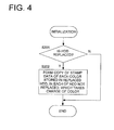
- Fig. 4 shows the replacement inspection process performed by the CPU 101 of the color image forming apparatus 10 during the initial process when the power source is turned on. Further, in this embodiment, the CPU 101 fulfills the function of the detection means. Firstly, the CPU 101 inspects whether there is the magnetic disk unit 120 exchanged or not (Step S201). For example, the CPU 101 checks whether predetermined use start information is registered in a specific area of the magnetic disk unit or not, and when it is not registered, decides that it is immediately after exchange, registers the use start information, and when it is registered already, decides that it is not immediately after exchange. Further, the inspection method is not limited to it and various methods can be adopted.
- Step S201: Y When there is the magnetic disk unit 120 exchanged (Step S201: Y), the CPU 101 prepares copies of the stamp data of each color stored in the replacement magnetic disk unit 120 in the existing magnetic disk units not exchanged (Step S202). At this time, the CPU 101, in each of the magnetic disk units, copies only the stamp data of the color that the concerned magnetic disk unit takes charge of colors from the replacement magnetic disk unit 120.
- Step S201: N the CPU 101 finishes the replacement inspection process without copying stamp data (End).
- the stamp data of each color registered in the replacement magnetic disk unit 120 is copied by the existing magnetic disk units taking charge of respective colors, so that in the image output operation, the general operation of reading and processing the stamp data individually and simultaneously from the magnetic disk units 112Y, 112M, 112C, and 112K taking charge of respective colors in parallel can be performed.
- the replacement magnetic disk unit 120 may take charge of magenta, so that after completion of the aforementioned copying, it is possible to erase the yellow, cyan, and black stamp data copied on the existing magnetic disk units from the replacement magnetic disk unit 120 and use the concerned part as a user area 121.
- image data of all colors is stored, so that one image storing device can be commonly used for exchange of an image storing device taking charge of any color, and control of each color is not required, thus the labor and cost of manufacture control of image storing devices can be reduced.
- the color image forming apparatus when an image storing device broken down is replaced with a replacement image storing device, the image data of each color stored in it beforehand is copied on the existing image storing devices, so that with respect to an image initially loaded on the replacement image forming apparatus, the image data of each color can be read from a plurality of image storing devices in parallel and can respond to a high-speed output process.
- the color image forming apparatus of this embodiment for storing dispersively image data of each color forming a color image in a plurality of image storing devices respectively taking charge of one or more colors, reading, from each image storing device, image data of its charging color, and forming a color image, when any of the plurality of image storing devices is replaced with the aforementioned image storing device, the image data of each color stored in it beforehand is copied on the existing image storing devices.
- a new image such as a new stamp image can be distributed. Further, image data of all colors may be copied on the existing image storing devices.
- the image data of each color stored in the image storing device after replacement is copied, so that after copying, the image data of each color initially loaded on the replacement image storing device can be read simultaneously from a plurality of image storing devices in parallel and can respond to a high-speed output process.
- the existing magnetic disk unit may be structured so as to copy stamp data of all colors on it.
- a device for storing an image is not limited to the magnetic disk unit and may be an image storing device of another type. However, it is preferably a nonvolatile large capacity storage for storing rewritably image data. Further, image data to be initially stored in the replacement magnetic disk unit 120 is not limited to image data overlaid with another image such as stamp data and another kind of image data is acceptable.
- an image forming apparatus having a loaded image storing device may use, among image data of all colors initially loaded thereon, image data of the color which the concerned replacement image storing device takes charge of. Further, image data of a color which the concerned device does not take charge of may be structured so as to be copied on another existing image storing device. Furthermore, the image forming apparatus may erase image data of an unnecessary color from the image storing device mounted and use the area as a general memory area.
Landscapes
- Engineering & Computer Science (AREA)
- Microelectronics & Electronic Packaging (AREA)
- Physics & Mathematics (AREA)
- General Physics & Mathematics (AREA)
- Record Information Processing For Printing (AREA)
- Control Or Security For Electrophotography (AREA)
- Color Electrophotography (AREA)
- Accessory Devices And Overall Control Thereof (AREA)
- Storing Facsimile Image Data (AREA)
- Editing Of Facsimile Originals (AREA)
- Color, Gradation (AREA)
Abstract
Description
- This application is based on Japanese Patent Application No. 2005-001531 filed on January 6, 2005 in Japanese Patent Office, the entire content of which is hereby incorporated by reference.
- The present invention relates to a color image forming apparatus for storing dispersively image data of each color forming a color image in a plurality of image storing devices respectively taking charge of one or more colors, a image storing device thereof and a manufacturing method of an image storing device.
- A color image forming apparatus such as a copier generally realizes a full-color using four colors of yellow (Y), magenta (M), cyan (C), and black (K) and inside the apparatus, the four colors are controlled by image data of each color. Further, to temporarily store an image, a large capacity magnetic disk unit is used. However, to realize high-speed input and output, four magnetic disk units by color are prepared and are operated in parallel, thus the four colors are processed simultaneously. By use of this constitution, compared with a case that image data by color are sequentially stored in one magnetic disk unit, a processing speed of practically four times is ensured.
- On the other hand, some copier has a stamp function for adding a stamp image such as "Strict Secrecy" or "Confidential" to a read document image and copying it and to realize this function, in a magnetic disk unit of an image forming apparatus, image data of an stamp image (hereinafter, referred to as "stamp data") is initially loaded at the time of shipment. In a color copier, a color-full stamp image such as the rainbow color is set and in a magnetic disk unit of each color, stamp data of its charging color is loaded initially.
- Patent Document 1: Japanese Patent Application 2001-100929.
- The magnetic disk unit is a mechanical part, which breaks down. Further, the life span thereof is generally shorter than that of the image forming apparatus, so that when the image forming apparatus is in use, a case that the magnetic disk unit must be exchanged occurs. Therefore, for the machine type having the stamp function, magnetic disk units for exchange having initially loaded stamp data are prepared at a parts center.
- However, in the color image forming apparatus, in each magnetic disk unit, stamp data of its charging color must be loaded initially, so that the parts center must prepare magnetic disk units for exchange for each color. For example, when a magnetic disk unit of yellow breaks down, an exclusive magnetic disk unit of yellow in which only yellow stamp data is initially loaded for exchange must be provided from the parts center and a problem arises that the labor and cost of parts control are increased.
- The present invention was developed to solve the aforementioned problem.
- An image storing devices for use in a color image forming apparatus for storing dispersively image data of each color constituting a color image in a plurality of image storing devices each taking charge of at least one color, reading image data of a charging color from each image storing device, and forming the color image, the image storing device comprising: an area for storing image data of each color for a color image to be stored beforehand, for all colors constituting the color image.
- A color image forming apparatus for storing dispersively image data of each color constituting a color image in a plurality of image storing devices each taking charge of at least one color, reading image data of a charging color from each image storing device, and forming the color image, wherein when any of the plurality of image storing devices is replaced with the image storing device described in
claim 1, image data of each color for a color image stored therein beforehand is copied to at least one of the image storing devices which have not been replaced. - A color image forming apparatus comprising: (a) a plurality of image storing devices each for storing at least one of image data of each color constituting a color image; (b) a controller for controlling so as to read the image data of each color in parallel from the image storing devices; and (c) image forming units for forming a color image, on the basis of the image data of each color read in parallel from the image storing devices, wherein the plurality of image storing devices store the image data for a color image to be stored beforehand, for all colors constituting the color image to be stored beforehand.
- A method for manufacturing an image storing device for use in a color image forming apparatus for stroing dispersively image data of each color constituting a color image in a plurality of image storing devices each taking charge of at least one color, reading image data of a charging color from each image storing device, and forming the color image, comprising the step of: storing image data of each color for a color image to be stored beforehand, for all colors constituting the color image to be stored beforehand.
-
- Fig. 1 is an illustration showing an example of stored contents of the replacement magnetic disk unit relating to the embodiment of the present invention.
- Fig. 2 is a cross sectional view showing the schematic constitution of the image forming apparatus relating to the embodiment of the present invention.
- Fig. 3 is a block diagram showing the electric constitution of the color image forming apparatus relating to the embodiment of the present invention.
- Fig. 4 is a flow chart showing the replacement inspection process performed by the color image forming apparatus relating to the embodiment of the present invention during the initial process when the power source is turned on.
- Hereinafter, the embodiment of the present invention will be explained with reference to the accompanying drawings.
- Fig. 2 is a cross sectional view showing the schematic constitution of a color
image forming apparatus 10 relating to the embodiment of the present invention. The colorimage forming apparatus 10 is an apparatus referred to as a color digital copier having a function for reading a document image in color, forming a copied color image thereof on a sheet of paper, and outputting it. - The color
image forming apparatus 10 has anautomatic document feeder 20, areading section 30, and aprinter section 40. The automatic document feeder 20 fulfills a function forfeeding documents 2 loaded on adocument tray 21 to the reading location of thereading section 30 one by one, and ejecting the read document to apaper ejection tray 27. Further, the apparatus has a function, for a double-sided document, for reading one side thereof, then turning it over, and feeding it again to thereading section 30. - The
automatic document feeder 20 includespaper supply rollers 22 for sequentially feeding documents stacked on the document tray 21 sequentially from the uppermost part thereof, ancontact roller 23 for passing a document in close contact withcontact glass 31 which is a document reading location, and aguide roller 24 for guiding the document fed by thepaper supply rollers 22 along thecontact roller 23. Further, the feeder includes aswitching pawl 25 for switching the moving direction of the document passing through thecontact glass 31,inversion rollers 26 for inverting a double-sided document, and the paper ejection tray 27 for ejecting the read document. - The
reading section 30 has a function for reading a document in color. In detail, the function divides a document into three colors such as red (R), green (G), and blue (B), optically reads them, and outputs image data of each color in which the three colors are converted to density data of four colors of yellow (Y), magenta (M), cyan (C), and black (K). - The
reading section 30 includes anexposure scanning unit 35 composed of a light source 33 and amirror 34, aline image sensor 36 of a color type for receiving reflected light from a document and outputting an electric signal of each color according to the light intensity thereof, a focusinglens 37 for focusing the reflected light from the document to theline image sensor 36, andvarious mirrors 38 for forming optical paths for introducing reflected light from themirror 34 of theexposure scanning unit 35 to theline image sensor 36. - When reading a document fed by the
automatic document feeder 20, theexposure scanning unit 35 moves and stops at the reading location under thecontact glass 31 and reads the document conveyed and moved thereon by thecontact roller 23. When reading a document loaded on aplaten glass 32, theexposure scanning unit 36 moves from left to right along the bottom of theplaten glass 32 and reads the document in the stopped state. - The
printer section 40 is a color printer of a tandem method using the electrophotographic method. Theprinter section 40 includes an endlessintermediate transfer belt 41, a plurality ofimage forming units intermediate transfer belt 41, apaper supply portion 70 for supplying transfer paper, aconveyor unit 80 for conveying supplied transfer paper, and afixing device 42. - The
image forming unit 50Y forms a yellow (Y) image on theintermediate transfer belt 41 and theimage forming unit 50M forms a magenta (M) image on theintermediate transfer belt 41. Theimage forming unit 50C forms a cyan (C) image on theintermediate transfer belt 41 and theimage forming unit 50K forms a black (K) image on theintermediate transfer belt 41. - The
image forming unit 50Y includes a cylindricalphotosensitive drum 51Y for forming an electrostatic latent image, amain charger 52Y arranged around it, a developingdevice 53Y, and acleaning device 54Y. Further, theimage forming unit 50Y includes alaser unit 55Y composed of a laser diode, a polygonal mirror, and various lenses and mirrors. - The
photosensitive drum 51Y is driven and rotated by a driving unit not illustrated in a fixed direction (the direction of an arrow A shown in the drawing) and themain charger 52Y uniformly charges thephotosensitive drum 51Y. Thelaser unit 55Y irradiates a laser beam turned on or off according to the yellow image data and forms an electrostatic latent image on thephotosensitive drum 51Y. The developingdevice 50Y visualizes the electrostatic latent image by yellow toner and the toner image is transferred to theintermediate transfer belt 41 at the contact location with theintermediate transfer belt 41. Thecleaning device 54Y fulfills a function for rubbing, removing, and collecting toner remaining on the surface of thephotosensitive drum 51Y after transfer by a blade. - The
image forming units image forming unit 50Y except that the toner colors are different and by image data corresponding to the respective colors, the laser beam is turned on or off, thus the respective explanation will be omitted. Further, to the same components, the same numeric characters are assigned and the suffix character Y is replaced with M, C, or K. - The
intermediate transfer belt 41 is supported rotatably by rotating a plurality of rollers. Theintermediate transfer belt 41 is rotated round by a driving means not illustrated in the direction of an arrow B. In the round rotation process, on theintermediate transfer belt 41, images of respective colors are superimposed in order of (Y), (M), (C), and (K) by theimage forming units intermediate transfer belt 41, is transferred to transfer paper from theintermediate transfer belt 41. Toner remained on theintermediate transfer belt 41 after transfer is removed by acleaning device 44. - The
paper supply portion 70 feeds transfer sheets of paper stored in respectivepaper supply cassettes 71 toward theconveyor unit 80 one by one from the uppermost part thereof by the firstpaper supply roller 72. Theconveyor unit 80 is composed of ageneral path 80a for ejecting the transfer sheets of paper sent from thepaper supply cassettes 71, after passing through the secondary transfer location C and thefixing device 42, to an external exit tray and areversal path 80b for reversing the display of the transfer sheets of paper passing through thefixing device 42 and then joining them again to thegeneral path 80a on the upstream side of the secondary transfer location C. Therespective paths many conveying rollers 81 at shorter intervals than the size of transfer paper of a minimum size in the feed direction. - Fig. 3 shows an electric schematic constitution of the color
image forming apparatus 10. The colorimage forming apparatus 10 has a CPU (central processing unit) 101 for generalizing and controlling the operation of the concerned devices. To theCPU 101, via asystem bus 102, in addition to thereading section 30 and theprinter section 40, a ROM (read only memory) 103, a RAM (random access memory) 104, an operation anddisplay section 105, anetwork control section 106, andimage blocks bus bridges - The
ROM 103 stores various programs executed by thesystem bus 102 and fixed data. TheRAM 104 is used as a work memory of theCPU 101. The operation anddisplay section 105 has a function for displaying various guides and states to a user and receiving various operations from the user. The operation anddisplay section 105 is composed of, for example, a liquid crystal display having a touch panel on its surface, various operation switches, and an operation section control CPU for controlling them. - The
network control section 106 is a circuit for transferring various data with an external computer via a network such as a LAN (local area network). - The image blocks 110Y, 110M, 110C, and 110K are circuit blocks for handling image data for each color, and the
image block 110Y takes charge of yellow image data, theimage block 110M magenta image data, theimage block 110C cyan image data, and theimage block 110K black image data. - The
image block 110Y has animage bus 111Y connected to the downstream side of acorresponding bus bridge 108Y and to it, amagnetic disk unit 112Y for storing image data and amemory control section 113Y are connected. To thememory control section 113Y, animage memory 114Y and a compression andexpansion section 115Y are connected. - To the
memory control section 113Y, yellow image data Yin inputted from thereading section 30 is input. Thememory control section 113Y has a function for compressing it by the compression andexpansion section 115Y and then writing it into theimage memory 114Y. Further, thememory control section 113Y has a function for expanding compressed yellow image data stored in theimage memory 114Y by the compression andexpansion section 115Y and re-storing it in theimage memory 114Y, sequentially reading the expanded yellow image data, and outputting it to theyellow laser unit 55Y of theprinter section 40. - Furthermore, the
image memory 114Y, at the access request from theimage bus 111Y, fulfills a function for writing image data on theimage bus 111Y into theimage memory 114Y and a function for outputting the image data read from theimage memory 114Y to theimage bus 111Y. - The image blocks 110M, 110C, and 110K have the same constitution as that of the
image block 110Y except that the colors of image data handled by them are different and operate similarly, so that here, detailed explanation will be omitted. Further, to the same components as those of theimage block 110Y, the same numeric characters whose suffix character Y is replaced with M, C, or K are assigned. -
Magnetic disk units reading section 30 by a user. For example, when an instruction to store image data read and obtained by thereading section 30 in the magnetic disk units is input from the user, among the image data read and obtained by thereading section 30, yellow image data is stored in theimage memory 114Y, then is compressed, and is stored in the user area of themagnetic disk unit 112Y for storing yellow image data. Similarly, magenta image data is stored in the user area of themagnetic disk unit 112M, cyan image data in the user area of thecyan disk unit 112C, and black image data in the user area of theblack disk unit 112K. - Further, when an instruction to form an image on the basis of the image data stored in the magnetic disk units is input from the user, the instructed image data are read in parallel from the
magnetic disk units image memories expansion sections magnetic disk units image forming apparatus 10 is purchased. In each stamp area of themagnetic disk units - Further, the color
image forming apparatus 10, when any of themagnetic disk units - Next, the operation of the color
image forming apparatus 10 will be explained. - Copying of a document is realized by combining an image input operation of reading a document image and compressing and storing it in the
image memories image memories printer section 40. In the image input operation, according to the document scanning operation, from thereading section 30, yellow image data Yin, magenta image data Min, cyan image data Cin, and black image data Kin are simultaneously output in parallel and are input to the image blocks 110Y, 110M, 110C, and 110K. - The image blocks 110Y, 110M, 110C, and 110K compress sequentially the image data respectively inputted to them and store them in the
image memories - In the image output operation, the image blocks 110Y, 110M, 110C, and 110K expand the image data stored in the
image memories expansion sections image memories printer section 40, from theimage memories printer section 40 in parallel. Theprinter section 40, on the basis of the yellow image data Yout, magenta image data Mout, cyan image data Cout, and black image data Kout which are input, forms and outputs a color image onto a sheet of paper. - Further, when designation of image output of the image data stored in the
magnetic disk units magnetic disk units image memories image memories expansion sections image memories printer section 40 in parallel and form and output a color image onto a sheet of paper. - Further, at the time of job setting, when addition of a stamp image is designated, stamp data of respective colors relating to the designated stamp image is read individually and simultaneously from the
magnetic disk units magnetic disk unit 112Y taking charge of yellow and the magenta stamp data is read from themagnetic disk unit 112M taking charge of magenta. Similarly, the cyan stamp data is read from themagnetic disk unit 112C taking charge of cyan and the black stamp data is read from themagnetic disk unit 112K taking charge of black. - The stamp data of respective colors read from the
magnetic disk units image memories image memories expansion sections image memories printer section 40 in parallel. - Further, designation of addition of the stamp image can be carried out by inputting from the operation and
display section 105 installed in theimage forming apparatus 10. However, it can be carried out by inputting from an external computer via the network control section. - Fig. 1 shows an example of the memory area of the replacement
magnetic disk unit 120. The replacementmagnetic disk unit 120 has auser area 121 and astamp area 122. In thestamp area 122,yellow stamp data 122Y,magenta stamp data 122M,cyan stamp data 122C, andblack stamp data 122K are stored beforehand. Data is stored in thestamp area 122, for example, at a factory before shipment to the parts center. Stamp data by color is stored for all colors in the replacementmagnetic disk unit 120 like this, so that the same replacementmagnetic disk unit 120 can be shared by all colors and compared with a case that the replacement magnetic disk unit is controlled for each color, the labor and cost of parts control are greatly reduced. - Fig. 4 shows the replacement inspection process performed by the
CPU 101 of the colorimage forming apparatus 10 during the initial process when the power source is turned on. Further, in this embodiment, theCPU 101 fulfills the function of the detection means. Firstly, theCPU 101 inspects whether there is themagnetic disk unit 120 exchanged or not (Step S201). For example, theCPU 101 checks whether predetermined use start information is registered in a specific area of the magnetic disk unit or not, and when it is not registered, decides that it is immediately after exchange, registers the use start information, and when it is registered already, decides that it is not immediately after exchange. Further, the inspection method is not limited to it and various methods can be adopted. - When there is the
magnetic disk unit 120 exchanged (Step S201: Y), theCPU 101 prepares copies of the stamp data of each color stored in the replacementmagnetic disk unit 120 in the existing magnetic disk units not exchanged (Step S202). At this time, theCPU 101, in each of the magnetic disk units, copies only the stamp data of the color that the concerned magnetic disk unit takes charge of colors from the replacementmagnetic disk unit 120. When there is not themagnetic disk unit 120 exchanged (Step S201: N), theCPU 101 finishes the replacement inspection process without copying stamp data (End). - After end of the replacement inspection process, the stamp data of each color registered in the replacement
magnetic disk unit 120 is copied by the existing magnetic disk units taking charge of respective colors, so that in the image output operation, the general operation of reading and processing the stamp data individually and simultaneously from themagnetic disk units - For example, when the magenta magnetic disk unit is replaced with the replacement
magnetic disk unit 120, the yellow stamp data is copied from the replacementmagnetic disk unit 120 onto themagnetic disk unit 112Y, and the cyan stamp data is copied from the replacementmagnetic disk unit 120 onto themagnetic disk unit 112C, and the black stamp data is copied from the replacementmagnetic disk unit 120 onto themagnetic disk unit 112K. Further, the replacementmagnetic disk unit 120 may take charge of magenta, so that after completion of the aforementioned copying, it is possible to erase the yellow, cyan, and black stamp data copied on the existing magnetic disk units from the replacementmagnetic disk unit 120 and use the concerned part as auser area 121. - According to the image storing device relating to the presentembodiment, for an image to be stored beforehand, image data of all colors is stored, so that one image storing device can be commonly used for exchange of an image storing device taking charge of any color, and control of each color is not required, thus the labor and cost of manufacture control of image storing devices can be reduced.
- Further, in the color image forming apparatus, when an image storing device broken down is replaced with a replacement image storing device, the image data of each color stored in it beforehand is copied on the existing image storing devices, so that with respect to an image initially loaded on the replacement image forming apparatus, the image data of each color can be read from a plurality of image storing devices in parallel and can respond to a high-speed output process.
- In the color image forming apparatus of this embodiment for storing dispersively image data of each color forming a color image in a plurality of image storing devices respectively taking charge of one or more colors, reading, from each image storing device, image data of its charging color, and forming a color image, when any of the plurality of image storing devices is replaced with the aforementioned image storing device, the image data of each color stored in it beforehand is copied on the existing image storing devices.
- By doing this, through the replacement image storing device, a new image such as a new stamp image can be distributed. Further, image data of all colors may be copied on the existing image storing devices.
- Further, in this embodiment, in the existing image storing devices, only for the respective charging colors, the image data of each color stored in the image storing device after replacement is copied, so that after copying, the image data of each color initially loaded on the replacement image storing device can be read simultaneously from a plurality of image storing devices in parallel and can respond to a high-speed output process.
- The embodiment of the present invention is explained above by referring to the drawings. However, the concrete constitution is not limited to the one indicated in the embodiment and modifications and additions within a range which is not deviated from the object of the present invention are included in the present invention.
- For example, in this embodiment, on an existing magnetic disk unit, only the stamp data of its charging color is copied from the replacement
magnetic disk unit 120. However, the existing magnetic disk unit may be structured so as to copy stamp data of all colors on it. - Further, a device for storing an image is not limited to the magnetic disk unit and may be an image storing device of another type. However, it is preferably a nonvolatile large capacity storage for storing rewritably image data. Further, image data to be initially stored in the replacement
magnetic disk unit 120 is not limited to image data overlaid with another image such as stamp data and another kind of image data is acceptable. - Further, an image forming apparatus having a loaded image storing device may use, among image data of all colors initially loaded thereon, image data of the color which the concerned replacement image storing device takes charge of. Further, image data of a color which the concerned device does not take charge of may be structured so as to be copied on another existing image storing device. Furthermore, the image forming apparatus may erase image data of an unnecessary color from the image storing device mounted and use the area as a general memory area.
Claims (20)
- An image storing devices for use in a color image forming apparatus for storing dispersively image data of each color constituting a color image in a plurality of image storing devices each taking charge of at least one color, reading image data of a charging color from each image storing device, and forming the color image, the image storing device comprising:an area for storing image data of each color for a color image to be stored beforehand, for all colors constituting the color image.
- The plurality of image storing devices of claim 1,
wherein the image storing device is an image storing device for replacement. - The plurality of image storing devices of claim 1 or 2, wherein the color image to be stored beforehand is an image to be overlaid with another image.
- The plurality of image storing devices of any one of claims 1 to 3, wherein the image storing device is a magnetic disk device.
- The plurality of image storing devices of claim 4,
wherein the magnetic disk device is a hard disk device. - A color image forming apparatus for storing dispersively image data of each color constituting a color image in a plurality of image storing devices each taking charge of at least one color, reading image data of a charging color from each image storing device, and forming the color image, wherein when any of the plurality of image storing devices is replaced with the image storing device described in any one of claims 1 to 5, image data of each color for a color image stored therein beforehand is copied to at least one of the image storing devices which have not been replaced.
- The color image forming apparatus of claim 6,
wherein the plurality of image storing devices are provided to correspond to each of the image data each color, the color image is formed by reading in parallel the image data from each of the plurality of image storing devices. - The color image forming apparatus of claim 6 or 7,
wherein the image data each color stored in the image storing device which has been replaced, is copied only to each of the image storing devices taking charge of the color, which have not been replaced. - The color image forming apparatus of any one of claims 6 to 8, further comprising a detector for detecting that the image storing device is replaced, wherein when the detector detects that the image storing device is replaced, data not stored in other image storing device among a color image data stored in the image storing device that has been replaced, is stored in the other image storing device.
- The color image forming apparatus of claim 9,
wherein when the detector detects that the image storing device is replaced, it is detected if there are data which are not stored in other image storing device among the color image data stored in the image storing device that has been replaced and a copy of the data not stored in other image storing device is stored in the other image storing device. - A color image forming apparatus comprising:(a) a plurality of image storing devices each for storing at least one of image data of each color constituting a color image;(b) a controller for controlling so as to read the image data of each color in parallel from the image storing devices; and(c) image forming units for forming a color image, on the basis of the image data of each color read in parallel from the image storing devices,wherein the plurality of image storing devices store the image data for a color image to be stored beforehand, for all colors constituting the color image to be stored beforehand.
- The color image forming apparatus of claim 11,
wherein the image storing device is an image storing device for replacement. - The color image forming apparatus of claim 11 or 12,
wherein the color image to be stored beforehand is an image to be overlaid with another image. - The color image forming apparatus of any one of claims 11 to 13, wherein the image storing device is a magnetic disk device.
- The color image forming apparatus of claim 14, wherein the magnetic disk device is a hard disk device.
- A method for manufacturing an image storing device for use in a color image forming apparatus for stroing dispersively image data of each color constituting a color image in a plurality of image storing devices each taking charge of at least one color, reading image data of a charging color from each image storing device, and forming the color image, comprising the step of:storing image data of each color for a color image to be stored beforehand, for all colors constituting the color image to be stored beforehand.
- The method of claim 16, wherein the image storing device is an image storing device for replacement.
- The method of claim 16 or 17, wherein the color image to be stored beforehand is an image to be overlaid with another image.
- The method of any one of claims 16 to 18, the image storing device is a magnetic disk device.
- The method of claim 19, wherein the magnetic disk device is a hard disk device.
Applications Claiming Priority (1)
| Application Number | Priority Date | Filing Date | Title |
|---|---|---|---|
| JP2005001531A JP3928732B2 (en) | 2005-01-06 | 2005-01-06 | Color image forming apparatus and image storage apparatus |
Publications (3)
| Publication Number | Publication Date |
|---|---|
| EP1679193A2 true EP1679193A2 (en) | 2006-07-12 |
| EP1679193A3 EP1679193A3 (en) | 2009-04-01 |
| EP1679193B1 EP1679193B1 (en) | 2013-03-13 |
Family
ID=36075511
Family Applications (1)
| Application Number | Title | Priority Date | Filing Date |
|---|---|---|---|
| EP05105529A Expired - Lifetime EP1679193B1 (en) | 2005-01-06 | 2005-06-22 | Color image forming apparatus and image storing device |
Country Status (4)
| Country | Link |
|---|---|
| US (1) | US20060146382A1 (en) |
| EP (1) | EP1679193B1 (en) |
| JP (1) | JP3928732B2 (en) |
| CN (1) | CN1801880B (en) |
Family Cites Families (20)
| Publication number | Priority date | Publication date | Assignee | Title |
|---|---|---|---|---|
| JPH01216860A (en) * | 1988-02-26 | 1989-08-30 | Dainippon Printing Co Ltd | thermal recording device |
| JPH0738716A (en) * | 1993-07-23 | 1995-02-07 | Ricoh Co Ltd | Image processing system |
| JPH08314329A (en) * | 1995-05-18 | 1996-11-29 | Ricoh Co Ltd | Color image forming device |
| DE69828830T2 (en) * | 1997-08-05 | 2006-01-05 | Sharp K.K. | Color image forming apparatus |
| JP3576782B2 (en) * | 1997-12-24 | 2004-10-13 | キヤノン株式会社 | Recording apparatus and recording control method |
| JP2000175023A (en) * | 1998-12-09 | 2000-06-23 | Sharp Corp | Image forming device |
| JP2002113905A (en) * | 2000-10-06 | 2002-04-16 | Fuji Xerox Co Ltd | Imaging device |
| GB2368412A (en) * | 2000-10-26 | 2002-05-01 | Hewlett Packard Co | Managing disk drive replacements |
| ATE490504T1 (en) * | 2001-03-19 | 2010-12-15 | Panasonic Corp | DATA RECEIVING SYSTEM WITH REPLACEABLE RECORDING MEDIUM AND METHOD THEREOF |
| JP2003048325A (en) * | 2001-08-06 | 2003-02-18 | Canon Inc | Recording device |
| US6678482B2 (en) * | 2001-09-17 | 2004-01-13 | Sharp Kabushiki Kaisha | Image forming apparatus and method for determining suitability of replaceable component |
| US7511861B2 (en) * | 2002-08-30 | 2009-03-31 | Hewlett-Packard Development Company, L.P. | Multi-page facsimile method and device |
| JP2004170863A (en) * | 2002-11-22 | 2004-06-17 | Fuji Xerox Co Ltd | Image forming apparatus, method for managing replacement component for use in the same, and program for managing the replacement component |
| JP4072424B2 (en) * | 2002-12-02 | 2008-04-09 | エルピーダメモリ株式会社 | Memory system and control method thereof |
| JP3952958B2 (en) * | 2003-01-22 | 2007-08-01 | キヤノン株式会社 | Image processing apparatus and image processing method |
| EP3174277B1 (en) * | 2003-02-25 | 2018-10-31 | SHARP Kabushiki Kaisha | Image processing apparatus |
| JP4243836B2 (en) * | 2003-03-04 | 2009-03-25 | セイコーエプソン株式会社 | Print control apparatus, print control program, and print control method |
| JP4125208B2 (en) * | 2003-09-29 | 2008-07-30 | キヤノン株式会社 | Image processing apparatus and image processing method |
| US20050273650A1 (en) * | 2004-06-07 | 2005-12-08 | Tsou Henry H | Systems and methods for backing up computer data to disk medium |
| US20060050326A1 (en) * | 2004-09-03 | 2006-03-09 | Kabushiki Kaisha Toshiba | Image processing apparatus, image processing method and image processing program |
-
2005
- 2005-01-06 JP JP2005001531A patent/JP3928732B2/en not_active Expired - Lifetime
- 2005-04-07 US US11/101,128 patent/US20060146382A1/en not_active Abandoned
- 2005-06-22 EP EP05105529A patent/EP1679193B1/en not_active Expired - Lifetime
- 2005-07-04 CN CN2005100821540A patent/CN1801880B/en not_active Expired - Lifetime
Also Published As
| Publication number | Publication date |
|---|---|
| CN1801880B (en) | 2013-05-29 |
| JP3928732B2 (en) | 2007-06-13 |
| JP2006190089A (en) | 2006-07-20 |
| EP1679193B1 (en) | 2013-03-13 |
| EP1679193A3 (en) | 2009-04-01 |
| CN1801880A (en) | 2006-07-12 |
| US20060146382A1 (en) | 2006-07-06 |
Similar Documents
| Publication | Publication Date | Title |
|---|---|---|
| JP4981265B2 (en) | Image forming apparatus | |
| US8447201B2 (en) | Image forming apparatus for controlling image density | |
| US20080292379A1 (en) | Image forming apparatus, image forming method, and computer program product | |
| EP2019341B1 (en) | Image forming apparatus | |
| EP1729496A1 (en) | Color image forming apparatus with plural image storing devices | |
| JPH10198109A (en) | Image forming device | |
| JPH0561385A (en) | Multicolor image forming device | |
| EP1679193B1 (en) | Color image forming apparatus and image storing device | |
| JP2002166592A (en) | Image forming device | |
| JP4105168B2 (en) | Image forming apparatus | |
| JP4928881B2 (en) | Image forming apparatus and phase matching control method | |
| JP2006262048A (en) | Image forming apparatus | |
| JP4379357B2 (en) | Color image forming apparatus | |
| JPH1146285A (en) | Image-forming device | |
| JP4158116B2 (en) | Image processing device | |
| US7933034B2 (en) | Image data processing circuit and image forming apparatus having the same | |
| JP2008257248A (en) | Image forming apparatus | |
| US7376367B2 (en) | Method of controlling fusing speed of image forming apparatus | |
| JP2006262047A (en) | Color image forming apparatus | |
| JP2004070152A (en) | Color image forming device | |
| JP2006221005A (en) | Image forming apparatus | |
| JP2014119632A (en) | Image forming apparatus | |
| KR20070089064A (en) | Image Forming Apparatus and Image Forming Method | |
| JP2009162841A (en) | Image forming apparatus | |
| JP2007295071A (en) | Color recording apparatus and image duplicating apparatus |
Legal Events
| Date | Code | Title | Description |
|---|---|---|---|
| PUAI | Public reference made under article 153(3) epc to a published international application that has entered the european phase |
Free format text: ORIGINAL CODE: 0009012 |
|
| AK | Designated contracting states |
Kind code of ref document: A2 Designated state(s): AT BE BG CH CY CZ DE DK EE ES FI FR GB GR HU IE IS IT LI LT LU MC NL PL PT RO SE SI SK TR |
|
| AX | Request for extension of the european patent |
Extension state: AL BA HR LV MK YU |
|
| PUAL | Search report despatched |
Free format text: ORIGINAL CODE: 0009013 |
|
| AK | Designated contracting states |
Kind code of ref document: A3 Designated state(s): AT BE BG CH CY CZ DE DK EE ES FI FR GB GR HU IE IS IT LI LT LU MC NL PL PT RO SE SI SK TR |
|
| AX | Request for extension of the european patent |
Extension state: AL BA HR LV MK YU |
|
| 17P | Request for examination filed |
Effective date: 20090903 |
|
| AKX | Designation fees paid |
Designated state(s): DE FR GB |
|
| 17Q | First examination report despatched |
Effective date: 20091125 |
|
| GRAP | Despatch of communication of intention to grant a patent |
Free format text: ORIGINAL CODE: EPIDOSNIGR1 |
|
| GRAS | Grant fee paid |
Free format text: ORIGINAL CODE: EPIDOSNIGR3 |
|
| GRAA | (expected) grant |
Free format text: ORIGINAL CODE: 0009210 |
|
| AK | Designated contracting states |
Kind code of ref document: B1 Designated state(s): DE FR GB |
|
| REG | Reference to a national code |
Ref country code: GB Ref legal event code: FG4D |
|
| REG | Reference to a national code |
Ref country code: DE Ref legal event code: R096 Ref document number: 602005038535 Country of ref document: DE Effective date: 20130508 |
|
| PLBE | No opposition filed within time limit |
Free format text: ORIGINAL CODE: 0009261 |
|
| STAA | Information on the status of an ep patent application or granted ep patent |
Free format text: STATUS: NO OPPOSITION FILED WITHIN TIME LIMIT |
|
| 26N | No opposition filed |
Effective date: 20131216 |
|
| REG | Reference to a national code |
Ref country code: DE Ref legal event code: R097 Ref document number: 602005038535 Country of ref document: DE Effective date: 20131216 |
|
| REG | Reference to a national code |
Ref country code: FR Ref legal event code: PLFP Year of fee payment: 12 |
|
| REG | Reference to a national code |
Ref country code: FR Ref legal event code: PLFP Year of fee payment: 13 |
|
| REG | Reference to a national code |
Ref country code: FR Ref legal event code: PLFP Year of fee payment: 14 |
|
| P01 | Opt-out of the competence of the unified patent court (upc) registered |
Effective date: 20230510 |
|
| PGFP | Annual fee paid to national office [announced via postgrant information from national office to epo] |
Ref country code: GB Payment date: 20240402 Year of fee payment: 20 |
|
| PGFP | Annual fee paid to national office [announced via postgrant information from national office to epo] |
Ref country code: DE Payment date: 20240328 Year of fee payment: 20 |
|
| PGFP | Annual fee paid to national office [announced via postgrant information from national office to epo] |
Ref country code: FR Payment date: 20240509 Year of fee payment: 20 |
|
| REG | Reference to a national code |
Ref country code: DE Ref legal event code: R071 Ref document number: 602005038535 Country of ref document: DE |
|
| PG25 | Lapsed in a contracting state [announced via postgrant information from national office to epo] |
Ref country code: GB Free format text: LAPSE BECAUSE OF EXPIRATION OF PROTECTION Effective date: 20250621 |
|
| REG | Reference to a national code |
Ref country code: GB Ref legal event code: PE20 Expiry date: 20250621 |