EP1679164A1 - Chainsaw bar adjustment assembly with breakaway adjustment pin - Google Patents
Chainsaw bar adjustment assembly with breakaway adjustment pin Download PDFInfo
- Publication number
- EP1679164A1 EP1679164A1 EP20060075022 EP06075022A EP1679164A1 EP 1679164 A1 EP1679164 A1 EP 1679164A1 EP 20060075022 EP20060075022 EP 20060075022 EP 06075022 A EP06075022 A EP 06075022A EP 1679164 A1 EP1679164 A1 EP 1679164A1
- Authority
- EP
- European Patent Office
- Prior art keywords
- pin
- bar adjustment
- adjustment
- shaft
- guide bar
- Prior art date
- Legal status (The legal status is an assumption and is not a legal conclusion. Google has not performed a legal analysis and makes no representation as to the accuracy of the status listed.)
- Withdrawn
Links
Images


Classifications
-
- B—PERFORMING OPERATIONS; TRANSPORTING
- B27—WORKING OR PRESERVING WOOD OR SIMILAR MATERIAL; NAILING OR STAPLING MACHINES IN GENERAL
- B27B—SAWS FOR WOOD OR SIMILAR MATERIAL; COMPONENTS OR ACCESSORIES THEREFOR
- B27B17/00—Chain saws; Equipment therefor
- B27B17/14—Arrangements for stretching the chain saw
- B27B17/144—Arrangements for stretching the chain saw with adjustment by at least one threaded screw
-
- Y—GENERAL TAGGING OF NEW TECHNOLOGICAL DEVELOPMENTS; GENERAL TAGGING OF CROSS-SECTIONAL TECHNOLOGIES SPANNING OVER SEVERAL SECTIONS OF THE IPC; TECHNICAL SUBJECTS COVERED BY FORMER USPC CROSS-REFERENCE ART COLLECTIONS [XRACs] AND DIGESTS
- Y10—TECHNICAL SUBJECTS COVERED BY FORMER USPC
- Y10T—TECHNICAL SUBJECTS COVERED BY FORMER US CLASSIFICATION
- Y10T83/00—Cutting
- Y10T83/707—By endless band or chain knife
- Y10T83/7226—With means to guard the tension
Definitions
- the present invention relates to guide bar adjustment mechanisms for chainsaws, and more particularly to an adjustment mechanism having a breakaway adjustment pin.
- a commonly used mechanism for adjusting the position of the guide bar consists of an adjustment pin threaded onto an adjustment screw provided on the body of the chainsaw.
- the adjustment pin engages a hole in the guide bar. As the adjustment screw is rotated, the pin advances or retreats along the screw, moving the guide bar with it.
- the present invention provides a bar adjustment assembly for a chainsaw including a self-aligning breakaway adjustment pin.
- the assembly comprises: a shaft, a bar adjustment pin journalled for rotation relative to the shaft, and a pin alignment spring biasing the rotation of the bar adjustment pin toward an engagement position.
- the assembly further comprises a void for accommodating the bar adjustment pin when the bar adjustment pin is rotated away from the engagement position.
- a guide bar adjustment mechanism 10 for a chainsaw includes a threaded shaft or adjustment screw 12, an adjustment pin 14 and a pin alignment spring 16.
- the adjustment screw 12 is mounted within a void or recess 18 provided in a portion of a chainsaw body 20
- the adjustment pin 14 is journalled on the adjustment screw 12. Matching threads are provided on the adjustment pin 14 and the adjustment screw 12.
- the adjustment screw 12 is rotated by using an appropriate tool on the head 12a of the adjustment screw 12, the adjustment pin 14 moves back and forth along the length of the adjustment screw 12.
- the guide bar 24 When the guide bar 24 is properly assembled onto the chainsaw body 20 (FIGS. 4 and 7), the adjustment pin 14 normally engages an adjustment hole or slot 22 in a guide bar 24. Due to the engagement of the adjustment hole 22 by the adjustment pin 14, as the adjustment pin 14 moves along the length of the adjustment screw 12, the guide bar 24 follows.
- the guide bar 24 is placed onto the chainsaw body 20 so that the adjustment pin protrudes through the adjustment hole 22 of the guide bar 24, as shown in FIGS. 4 and 7. Then, a cover portion 25 of the chainsaw is placed over the guide bar 24 and chainsaw body 20. The cover portion 25 is secured in place by two bolts 26 or other fasteners (see FIG. 1).
- the recess 18 is shaped to allow the guide pin 14 to pivot fully into the recess 18. Therefore, if the guide bar 24 is incorrectly positioned on the chainsaw body 20, such that the adjustment hole 22 is not aligned with the adjustment pin 14, the adjustment pin 14 can pivot out of the way, preventing damage to the adjustment mechanism 10 from occurring (FIGS. 3 and 6).
- the pin alignment spring 16 is a helical torsion spring provided on the adjustment screw to keep the adjustment pin 14 in the correct orientation when the guide bar 24 is not attached.
- the pin alignment spring 16 is a helical torsion spring having first and second free ends (27, 28). The first end 27 of the pin alignment spring 16 engages the adjustment pin 14, and the second end of the pin alignment spring 16 engages a surface of the chainsaw body 20 within the recess 18.
- the pin alignment spring 16 is loosely wrapped on the adjustment screw 12, such that it is journalled thereon, to allow the pin alignment spring 16 to travel along the adjustment screw 12 with the adjustment pin 14.
- springs such as a helical tension spring, a helical compression spring, a spiral spring, a flat spring, etc., or other known types of biasing means such as elastic bands or straps, resilient foam or gel pads, etc., can be provided as the pin alignment means.
- the pin alignment spring 16 is positioned to bias the pivoting of the adjustment pin 14 out of the recess 18.
- a stop surface 30 meets a surface 31 of the chainsaw body 20 within the recess 18. This meeting of the two surfaces 30, 31 prevents the adjustment pin 14 from pivoting any further.
- other stop mechanisms could be used.
- the adjustment pin 14 pivots into the recess 18.
- the alignment spring 16 causes the adjustment pin 14 to pivot to its fully upright position so that the guide bar 24, now being correctly aligned, can be reassembled without any manual repositioning of the adjustment pin 14.
Landscapes
- Life Sciences & Earth Sciences (AREA)
- Engineering & Computer Science (AREA)
- Mechanical Engineering (AREA)
- Wood Science & Technology (AREA)
- Forests & Forestry (AREA)
- Devices For Conveying Motion By Means Of Endless Flexible Members (AREA)
- Sawing (AREA)
Abstract
Description
- The present invention relates to guide bar adjustment mechanisms for chainsaws, and more particularly to an adjustment mechanism having a breakaway adjustment pin.
- Various mechanisms are known for adjusting the tension of the chain on a chainsaw. Nearly all of these mechanisms involve the movement of the guide bar upon which the chain rests. By lengthening the guide bar, the chain tension is increased. Conversely, shortening the guide bar decreases the chain tension.
- A commonly used mechanism for adjusting the position of the guide bar consists of an adjustment pin threaded onto an adjustment screw provided on the body of the chainsaw. The adjustment pin engages a hole in the guide bar. As the adjustment screw is rotated, the pin advances or retreats along the screw, moving the guide bar with it.
- One problem with these adjustment pin type chain tensioning mechanisms occurs during assembly of the guide bar onto the chainsaw body. The pin is not normally visible once the bar is placed onto the body. If the guide bar and the adjustment pin are not properly aligned during assembly, the adjustment pin and/or adjustment screw can be damaged.
- The present invention provides a bar adjustment assembly for a chainsaw including a self-aligning breakaway adjustment pin. The assembly comprises: a shaft, a bar adjustment pin journalled for rotation relative to the shaft, and a pin alignment spring biasing the rotation of the bar adjustment pin toward an engagement position.
- According to a further aspect of the present invention, the assembly further comprises a void for accommodating the bar adjustment pin when the bar adjustment pin is rotated away from the engagement position.
-
- FIG. 1 is an overall view of a chainsaw having a guide bar adjustment mechanism according to the present invention;
- FIG. 2 is a plan view of a portion of a chainsaw body that houses a guide bar adjustment mechanism according to the present invention;
- FIG. 3 is a plan view of the chainsaw body of FIG. 2 having a misaligned guide bar attached thereto;
- FIG. 4 is a plan view of the chainsaw body of FIG. 2 having a correctly aligned guide bar attached thereto;
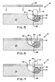
- FIG. 5 is a cross section of the chainsaw body and guide bar adjustment mechanism taken along section line 5-5 of FIG. 2 showing the assembly direction of the guide bar;
- FIG. 6 is a cross section of the chainsaw body and guide bar adjustment mechanism taken along section line 6-6 of FIG. 3; and
- FIG. 7 is a cross section of the chainsaw body and guide bar adjustment mechanism taken along section line 7-7 of FIG. 4.
- As shown in FIGS. 1-7, a guide
bar adjustment mechanism 10 for a chainsaw includes a threaded shaft oradjustment screw 12, anadjustment pin 14 and apin alignment spring 16. Theadjustment screw 12 is mounted within a void orrecess 18 provided in a portion of achainsaw body 20 Theadjustment pin 14 is journalled on theadjustment screw 12. Matching threads are provided on theadjustment pin 14 and theadjustment screw 12. When theadjustment screw 12 is rotated by using an appropriate tool on thehead 12a of theadjustment screw 12, theadjustment pin 14 moves back and forth along the length of theadjustment screw 12. When theguide bar 24 is properly assembled onto the chainsaw body 20 (FIGS. 4 and 7), theadjustment pin 14 normally engages an adjustment hole orslot 22 in aguide bar 24. Due to the engagement of theadjustment hole 22 by theadjustment pin 14, as theadjustment pin 14 moves along the length of theadjustment screw 12, theguide bar 24 follows. - During assembly of the chainsaw, as illustrated in FIG. 4, the
guide bar 24 is placed onto thechainsaw body 20 so that the adjustment pin protrudes through theadjustment hole 22 of theguide bar 24, as shown in FIGS. 4 and 7. Then, acover portion 25 of the chainsaw is placed over theguide bar 24 andchainsaw body 20. Thecover portion 25 is secured in place by twobolts 26 or other fasteners (see FIG. 1). - As shown by the broken lines in FIG. 5, the
recess 18 is shaped to allow theguide pin 14 to pivot fully into therecess 18. Therefore, if theguide bar 24 is incorrectly positioned on thechainsaw body 20, such that theadjustment hole 22 is not aligned with theadjustment pin 14, theadjustment pin 14 can pivot out of the way, preventing damage to theadjustment mechanism 10 from occurring (FIGS. 3 and 6). - The
pin alignment spring 16 is a helical torsion spring provided on the adjustment screw to keep theadjustment pin 14 in the correct orientation when theguide bar 24 is not attached. Thepin alignment spring 16 is a helical torsion spring having first and second free ends (27, 28). Thefirst end 27 of thepin alignment spring 16 engages theadjustment pin 14, and the second end of thepin alignment spring 16 engages a surface of thechainsaw body 20 within therecess 18. Thepin alignment spring 16 is loosely wrapped on theadjustment screw 12, such that it is journalled thereon, to allow thepin alignment spring 16 to travel along theadjustment screw 12 with theadjustment pin 14. Alternatively, other types of springs, such as a helical tension spring, a helical compression spring, a spiral spring, a flat spring, etc., or other known types of biasing means such as elastic bands or straps, resilient foam or gel pads, etc., can be provided as the pin alignment means. - The
pin alignment spring 16 is positioned to bias the pivoting of theadjustment pin 14 out of therecess 18. When theadjustment pin 14 is positioned fully upright in an engagement position, as shown in FIGS. 2, 5 and 7, astop surface 30 meets asurface 31 of thechainsaw body 20 within therecess 18. This meeting of the twosurfaces adjustment pin 14 from pivoting any further. Alternatively, other stop mechanisms could be used. - As described above, when the
guide bar 24 is incorrectly positioned on thechainsaw body 20, theadjustment pin 14 pivots into therecess 18. When theguide bar 24 is subsequently removed from thechainsaw body 20, thealignment spring 16 causes theadjustment pin 14 to pivot to its fully upright position so that theguide bar 24, now being correctly aligned, can be reassembled without any manual repositioning of theadjustment pin 14. - It should be evident that this disclosure is by way of example and that various changes may be made by adding, modifying or eliminating details without departing from the fair scope of the teaching contained in this disclosure. The invention is therefore not limited to particular details of this disclosure except to the extent that the following claims are necessarily so limited.
Claims (15)
- A guide bar adjustment assembly for a chain saw, the assembly comprising:a shaft;a bar adjustment pinjournalled for rotation relative to the shaft; anda pin alignment spring biasing the rotation of the bar adjustment pin toward an engagement position.
- The guide bar adjustment assembly of claim 1, further comprising a void for accommodating the bar adjustment pin when the bar adjustment pin is rotated away from the engagement position.
- The guide bar adjustment assembly of claim 1, wherein the shaft comprises an outside thread and the bar adjustment pin is threadedly engaged with the shaft for translation along a longitudinal axis of the shaft upon rotation of the shaft.
- The guide bar adjustment assembly of claim 1, further comprising a stop mechanism for preventing the pin alignment spring from rotating the bar adjustment pin past the engagement position.
- The guide bar adjustment assembly of claim 1, wherein the pin alignment spring is a helical torsion spring journalled on the shaft.
- The guide bar adjustment assembly of claim 1, wherein the pin alignment spring comprises an extension at an end of the pin alignment spring, the extension engaging the bar adjustment pin.
- A guide bar adjustment assembly for a chain saw, the assembly comprising:adjustment means for adjusting a position of the guide bar, the adjustment means comprising a moveable bar adjustment pin; andalignment means for automatically aligning the bar adjustment pin.
- The guide bar adjustment assembly of claim 7, further comprising means for accommodating the bar adjustment pin when the guide bar is misaligned.
- The guide bar adjustment assembly of claim 7, wherein the pin alignment means is a helical torsion spring.
- A chainsaw comprising:a chainsaw body;a guide bar having an adjustment hole for slidably mounting onto the chainsaw body;a bar adjustment shaft;a bar adjustment pinjournalled for rotation about the shaft; anda pin alignment spring biasing the rotation of the bar adjustment pin toward an engagement position for insertion into the adjustment hole of the guide bar when the guide bar is mounted on the chainsaw body.
- The chainsaw of claim 10, wherein the chainsaw body comprises a void for accommodating the bar adjustment pin when the bar adjustment pin is rotated away from the engagement position.
- The chainsaw of claim 10, wherein the shaft comprises an outside thread and the bar adjustment pin is threadedly engaged with the shaft for translation along a longitudinal axis of the shaft upon rotation of the shaft.
- The chainsaw of claim 10, further comprising a stop mechanism for preventing the pin alignment spring from rotating the bar adjustment pin past the engagement position.
- The chainsaw of claim 10, wherein the pin alignment spring is a helical torsion spring journalled on the shaft.
- The chainsaw of claim 10, wherein the pin alignment spring comprises an extension at an end of the pin alignment spring, the extension engaging the bar adjustment pin.
Applications Claiming Priority (1)
| Application Number | Priority Date | Filing Date | Title |
|---|---|---|---|
| US11/032,989 US7481000B2 (en) | 2005-01-10 | 2005-01-10 | Chainsaw bar adjustment assembly with breakaway adjustment pin |
Publications (1)
| Publication Number | Publication Date |
|---|---|
| EP1679164A1 true EP1679164A1 (en) | 2006-07-12 |
Family
ID=36103853
Family Applications (1)
| Application Number | Title | Priority Date | Filing Date |
|---|---|---|---|
| EP20060075022 Withdrawn EP1679164A1 (en) | 2005-01-10 | 2006-01-04 | Chainsaw bar adjustment assembly with breakaway adjustment pin |
Country Status (6)
| Country | Link |
|---|---|
| US (1) | US7481000B2 (en) |
| EP (1) | EP1679164A1 (en) |
| JP (1) | JP2006191926A (en) |
| CN (1) | CN100475396C (en) |
| CA (1) | CA2523662A1 (en) |
| TW (1) | TW200624237A (en) |
Cited By (1)
| Publication number | Priority date | Publication date | Assignee | Title |
|---|---|---|---|---|
| RU2453423C2 (en) * | 2007-02-26 | 2012-06-20 | Пелленк | Saw chain with tensioner |
Families Citing this family (15)
| Publication number | Priority date | Publication date | Assignee | Title |
|---|---|---|---|---|
| DE602008001000D1 (en) * | 2007-02-20 | 2010-06-02 | Bosch Gmbh Robert | Decoupling mechanism for power tools |
| PL2777901T3 (en) * | 2007-10-12 | 2017-10-31 | Husqvarna Ab | Attaching arrangement for hand-held motor-driven tools |
| JP5314496B2 (en) * | 2009-05-20 | 2013-10-16 | 株式会社マキタ | Chainsaw |
| JP5486214B2 (en) | 2009-05-20 | 2014-05-07 | 株式会社マキタ | Power tools |
| JP5396149B2 (en) | 2009-05-20 | 2014-01-22 | 株式会社マキタ | Power tools |
| JP5486325B2 (en) * | 2010-01-21 | 2014-05-07 | 株式会社丸山製作所 | Chain saw |
| WO2012105876A1 (en) | 2011-02-03 | 2012-08-09 | Husqvarna Ab | Wall or floor saw |
| DE102012215452A1 (en) * | 2012-08-31 | 2014-03-06 | Robert Bosch Gmbh | 1Werkzeugmaschinensystem |
| JP6026943B2 (en) * | 2013-03-29 | 2016-11-16 | 株式会社マキタ | Chainsaw guide bar fastening device |
| JP6132626B2 (en) * | 2013-03-29 | 2017-05-24 | 株式会社マキタ | Portable work machine |
| CN103223680B (en) * | 2013-04-08 | 2015-04-08 | 浙江中马园林机器股份有限公司 | Tightness adjusting mechanism for chain saw chain |
| WO2017028202A1 (en) | 2015-08-18 | 2017-02-23 | Black & Decker Inc. | Low profile chainsaw |
| US11343973B2 (en) | 2018-05-23 | 2022-05-31 | Milwaukee Electric Tool Corporation | Pole saw |
| CN108834822A (en) * | 2018-08-08 | 2018-11-20 | 浙江亚特电器有限公司 | A kind of chain saw |
| CN120396060A (en) * | 2025-05-16 | 2025-08-01 | 宁波鲁仕锯链科技有限公司 | Portable manual sawing tool, processing method and use method |
Citations (6)
| Publication number | Priority date | Publication date | Assignee | Title |
|---|---|---|---|---|
| US3194284A (en) * | 1963-06-05 | 1965-07-13 | Charles M Walker | Tension adjusting means for chain saws |
| US4026020A (en) * | 1975-03-05 | 1977-05-31 | Andreas Stihl Maschinenfabrik | Guiding rail arresting device for motor driven saws |
| US4835868A (en) * | 1986-12-17 | 1989-06-06 | Kioritz Corporation | Saw chain tensioner of chain saw |
| JPH07314402A (en) * | 1994-05-30 | 1995-12-05 | Kioritz Corp | Chainsaw |
| US20040148788A1 (en) * | 2002-11-15 | 2004-08-05 | Shane Behbahany | Chainsaw bar tensioning apparatus |
| WO2004103657A1 (en) * | 2003-05-20 | 2004-12-02 | Komatsu Zenoah Co. | Auto chain tensioner |
Family Cites Families (7)
| Publication number | Priority date | Publication date | Assignee | Title |
|---|---|---|---|---|
| US2645254A (en) * | 1949-06-16 | 1953-07-14 | Carl Van Ausdall | Tension adjusting means for chain saws or the like |
| US4382334A (en) * | 1981-07-01 | 1983-05-10 | Omark Industries, Inc. | Chain saw device |
| DE4219956C2 (en) * | 1992-06-18 | 2000-03-30 | Stihl Maschf Andreas | Cutting device for a motor chain saw |
| SE509726C2 (en) * | 1993-10-13 | 1999-03-01 | Electrolux Ab | Chain tensioner for chainsaw |
| US5528835A (en) * | 1994-11-29 | 1996-06-25 | Ra; Do-Jin | Chain saw tensioning apparatus |
| GB2374037B (en) * | 2001-04-04 | 2003-06-04 | Bosch Gmbh Robert | Releasable tool fastening mechanism and tool for use therewith |
| US6560879B2 (en) | 2001-08-02 | 2003-05-13 | Wci Outdoor Products, Inc. | Chain saw adjuster |
-
2005
- 2005-01-10 US US11/032,989 patent/US7481000B2/en not_active Expired - Fee Related
- 2005-09-30 TW TW094134185A patent/TW200624237A/en unknown
- 2005-10-17 CA CA 2523662 patent/CA2523662A1/en not_active Abandoned
- 2005-10-21 CN CNB2005101142693A patent/CN100475396C/en not_active Expired - Fee Related
- 2005-12-02 JP JP2005348763A patent/JP2006191926A/en not_active Withdrawn
-
2006
- 2006-01-04 EP EP20060075022 patent/EP1679164A1/en not_active Withdrawn
Patent Citations (7)
| Publication number | Priority date | Publication date | Assignee | Title |
|---|---|---|---|---|
| US3194284A (en) * | 1963-06-05 | 1965-07-13 | Charles M Walker | Tension adjusting means for chain saws |
| US4026020A (en) * | 1975-03-05 | 1977-05-31 | Andreas Stihl Maschinenfabrik | Guiding rail arresting device for motor driven saws |
| US4835868A (en) * | 1986-12-17 | 1989-06-06 | Kioritz Corporation | Saw chain tensioner of chain saw |
| JPH07314402A (en) * | 1994-05-30 | 1995-12-05 | Kioritz Corp | Chainsaw |
| US20040148788A1 (en) * | 2002-11-15 | 2004-08-05 | Shane Behbahany | Chainsaw bar tensioning apparatus |
| WO2004103657A1 (en) * | 2003-05-20 | 2004-12-02 | Komatsu Zenoah Co. | Auto chain tensioner |
| EP1637299A1 (en) * | 2003-05-20 | 2006-03-22 | Komatsu Zenoah Co. | Auto chain tensioner |
Non-Patent Citations (1)
| Title |
|---|
| PATENT ABSTRACTS OF JAPAN vol. 1996, no. 04 30 April 1996 (1996-04-30) * |
Cited By (1)
| Publication number | Priority date | Publication date | Assignee | Title |
|---|---|---|---|---|
| RU2453423C2 (en) * | 2007-02-26 | 2012-06-20 | Пелленк | Saw chain with tensioner |
Also Published As
| Publication number | Publication date |
|---|---|
| TW200624237A (en) | 2006-07-16 |
| JP2006191926A (en) | 2006-07-27 |
| US7481000B2 (en) | 2009-01-27 |
| CN1803357A (en) | 2006-07-19 |
| CN100475396C (en) | 2009-04-08 |
| US20060150427A1 (en) | 2006-07-13 |
| CA2523662A1 (en) | 2006-07-10 |
Similar Documents
| Publication | Publication Date | Title |
|---|---|---|
| US7481000B2 (en) | Chainsaw bar adjustment assembly with breakaway adjustment pin | |
| DE69901603T2 (en) | BELT TENSIONER FOR A MOTOR VEHICLE | |
| KR100996930B1 (en) | Tensioner | |
| US6049986A (en) | Chain saw guide bar equipped with chain tensioner | |
| KR101530213B1 (en) | Power tool for stainless steel metal locking ties | |
| US5820503A (en) | Tensioner for traction means with predefined tensioning displacement | |
| US8257212B2 (en) | Chain tensioner | |
| PL205953B1 (en) | Belt tensioner with installation pin | |
| EP3810960B1 (en) | Tensioner | |
| TWI657896B (en) | Torque wrench | |
| US5000232A (en) | Manual band installation tool | |
| JP2008544195A (en) | Mechanical chain tensioner with followable blade spring | |
| BRPI0412098B1 (en) | ADJUSTABLE TENSIONER | |
| US20090215563A1 (en) | Tensioner for a traction means such as a belt or the like | |
| US4505691A (en) | Universal tightener for a transmission chain or belt | |
| US6679363B1 (en) | Ratcheting tool with spring-urged pawls and method | |
| US7185437B2 (en) | Chainsaw bar tensioning apparatus | |
| US20090254187A1 (en) | Tightenable Surgical Retractor Joint | |
| US11034472B2 (en) | Band tensioning tool and calibration device therefor | |
| US20080141544A1 (en) | Keyless adjusting mechanism for chain saw | |
| US20060179668A1 (en) | Device for adjusting foot plate of a jigsaw | |
| US9381666B1 (en) | Automatic chainsaw tensioning device | |
| US11326669B2 (en) | Chain tensioner and tensioner body | |
| CN113001627B (en) | Table saw fence with adjustment mechanism | |
| CN101263320A (en) | Track shoe tensioner for timing belt drives used with oil |
Legal Events
| Date | Code | Title | Description |
|---|---|---|---|
| PUAI | Public reference made under article 153(3) epc to a published international application that has entered the european phase |
Free format text: ORIGINAL CODE: 0009012 |
|
| AK | Designated contracting states |
Kind code of ref document: A1 Designated state(s): AT BE BG CH CY CZ DE DK EE ES FI FR GB GR HU IE IS IT LI LT LU LV MC NL PL PT RO SE SI SK TR |
|
| AX | Request for extension of the european patent |
Extension state: AL BA HR MK YU |
|
| 17P | Request for examination filed |
Effective date: 20070108 |
|
| RAP1 | Party data changed (applicant data changed or rights of an application transferred) |
Owner name: HUSQVARNA OUTDOOR PRODUCTS, INC. |
|
| AKX | Designation fees paid |
Designated state(s): AT BE BG CH CY CZ DE DK EE ES FI FR GB GR HU IE IS IT LI LT LU LV MC NL PL PT RO SE SI SK TR |
|
| 17Q | First examination report despatched |
Effective date: 20070426 |
|
| RAP1 | Party data changed (applicant data changed or rights of an application transferred) |
Owner name: HUSQVARNA CONSUMER OUTDOOR PRODUCTS N.A., INC. |
|
| STAA | Information on the status of an ep patent application or granted ep patent |
Free format text: STATUS: THE APPLICATION HAS BEEN WITHDRAWN |
|
| 18W | Application withdrawn |
Effective date: 20110303 |