EP1679057A1 - Container manufacturing device - Google Patents
Container manufacturing device Download PDFInfo
- Publication number
- EP1679057A1 EP1679057A1 EP04792116A EP04792116A EP1679057A1 EP 1679057 A1 EP1679057 A1 EP 1679057A1 EP 04792116 A EP04792116 A EP 04792116A EP 04792116 A EP04792116 A EP 04792116A EP 1679057 A1 EP1679057 A1 EP 1679057A1
- Authority
- EP
- European Patent Office
- Prior art keywords
- needle
- instilling
- ptc heater
- container body
- container
- Prior art date
- Legal status (The legal status is an assumption and is not a legal conclusion. Google has not performed a legal analysis and makes no representation as to the accuracy of the status listed.)
- Withdrawn
Links
- 238000004519 manufacturing process Methods 0.000 title claims abstract description 33
- 239000007788 liquid Substances 0.000 claims abstract description 26
- 238000010438 heat treatment Methods 0.000 claims abstract description 12
- 239000012815 thermoplastic material Substances 0.000 claims abstract description 7
- 239000000126 substance Substances 0.000 abstract 2
- 239000003889 eye drop Substances 0.000 description 14
- 229940012356 eye drops Drugs 0.000 description 14
- 238000000034 method Methods 0.000 description 11
- 239000006196 drop Substances 0.000 description 8
- 238000000071 blow moulding Methods 0.000 description 6
- 230000005611 electricity Effects 0.000 description 6
- 238000007666 vacuum forming Methods 0.000 description 6
- 238000000465 moulding Methods 0.000 description 4
- 229910052736 halogen Inorganic materials 0.000 description 3
- 150000002367 halogens Chemical class 0.000 description 3
- 239000000463 material Substances 0.000 description 3
- -1 polyethylene Polymers 0.000 description 3
- 230000008569 process Effects 0.000 description 3
- 239000004696 Poly ether ether ketone Substances 0.000 description 2
- 239000004698 Polyethylene Substances 0.000 description 2
- 239000004743 Polypropylene Substances 0.000 description 2
- 238000005299 abrasion Methods 0.000 description 2
- 229910002113 barium titanate Inorganic materials 0.000 description 2
- 239000011248 coating agent Substances 0.000 description 2
- 238000000576 coating method Methods 0.000 description 2
- 230000006698 induction Effects 0.000 description 2
- 229920002530 polyetherether ketone Polymers 0.000 description 2
- 229920000573 polyethylene Polymers 0.000 description 2
- 229920001155 polypropylene Polymers 0.000 description 2
- 239000011347 resin Substances 0.000 description 2
- 229920005989 resin Polymers 0.000 description 2
- OKTJSMMVPCPJKN-UHFFFAOYSA-N Carbon Chemical compound [C] OKTJSMMVPCPJKN-UHFFFAOYSA-N 0.000 description 1
- JRPBQTZRNDNNOP-UHFFFAOYSA-N barium titanate Chemical compound [Ba+2].[Ba+2].[O-][Ti]([O-])([O-])[O-] JRPBQTZRNDNNOP-UHFFFAOYSA-N 0.000 description 1
- 230000015572 biosynthetic process Effects 0.000 description 1
- 229910052799 carbon Inorganic materials 0.000 description 1
- 239000000919 ceramic Substances 0.000 description 1
- 238000010276 construction Methods 0.000 description 1
- 238000001816 cooling Methods 0.000 description 1
- 230000003247 decreasing effect Effects 0.000 description 1
- 230000003292 diminished effect Effects 0.000 description 1
- 230000008570 general process Effects 0.000 description 1
- 238000002372 labelling Methods 0.000 description 1
- 230000001050 lubricating effect Effects 0.000 description 1
- 238000005259 measurement Methods 0.000 description 1
- 239000000203 mixture Substances 0.000 description 1
- 238000004806 packaging method and process Methods 0.000 description 1
- 230000002093 peripheral effect Effects 0.000 description 1
- 229920000515 polycarbonate Polymers 0.000 description 1
- 239000004417 polycarbonate Substances 0.000 description 1
- 229920000139 polyethylene terephthalate Polymers 0.000 description 1
- 239000005020 polyethylene terephthalate Substances 0.000 description 1
- 238000007789 sealing Methods 0.000 description 1
- 239000004065 semiconductor Substances 0.000 description 1
Images


Classifications
-
- B—PERFORMING OPERATIONS; TRANSPORTING
- B65—CONVEYING; PACKING; STORING; HANDLING THIN OR FILAMENTARY MATERIAL
- B65D—CONTAINERS FOR STORAGE OR TRANSPORT OF ARTICLES OR MATERIALS, e.g. BAGS, BARRELS, BOTTLES, BOXES, CANS, CARTONS, CRATES, DRUMS, JARS, TANKS, HOPPERS, FORWARDING CONTAINERS; ACCESSORIES, CLOSURES, OR FITTINGS THEREFOR; PACKAGING ELEMENTS; PACKAGES
- B65D1/00—Rigid or semi-rigid containers having bodies formed in one piece, e.g. by casting metallic material, by moulding plastics, by blowing vitreous material, by throwing ceramic material, by moulding pulped fibrous material or by deep-drawing operations performed on sheet material
- B65D1/02—Bottles or similar containers with necks or like restricted apertures, designed for pouring contents
- B65D1/08—Bottles or similar containers with necks or like restricted apertures, designed for pouring contents adapted to discharge drops
-
- A—HUMAN NECESSITIES
- A61—MEDICAL OR VETERINARY SCIENCE; HYGIENE
- A61F—FILTERS IMPLANTABLE INTO BLOOD VESSELS; PROSTHESES; DEVICES PROVIDING PATENCY TO, OR PREVENTING COLLAPSING OF, TUBULAR STRUCTURES OF THE BODY, e.g. STENTS; ORTHOPAEDIC, NURSING OR CONTRACEPTIVE DEVICES; FOMENTATION; TREATMENT OR PROTECTION OF EYES OR EARS; BANDAGES, DRESSINGS OR ABSORBENT PADS; FIRST-AID KITS
- A61F9/00—Methods or devices for treatment of the eyes; Devices for putting in contact-lenses; Devices to correct squinting; Apparatus to guide the blind; Protective devices for the eyes, carried on the body or in the hand
- A61F9/0008—Introducing ophthalmic products into the ocular cavity or retaining products therein
-
- B—PERFORMING OPERATIONS; TRANSPORTING
- B26—HAND CUTTING TOOLS; CUTTING; SEVERING
- B26F—PERFORATING; PUNCHING; CUTTING-OUT; STAMPING-OUT; SEVERING BY MEANS OTHER THAN CUTTING
- B26F1/00—Perforating; Punching; Cutting-out; Stamping-out; Apparatus therefor
- B26F1/24—Perforating by needles or pins
-
- B—PERFORMING OPERATIONS; TRANSPORTING
- B29—WORKING OF PLASTICS; WORKING OF SUBSTANCES IN A PLASTIC STATE IN GENERAL
- B29C—SHAPING OR JOINING OF PLASTICS; SHAPING OF MATERIAL IN A PLASTIC STATE, NOT OTHERWISE PROVIDED FOR; AFTER-TREATMENT OF THE SHAPED PRODUCTS, e.g. REPAIRING
- B29C57/00—Shaping of tube ends, e.g. flanging, belling or closing; Apparatus therefor, e.g. collapsible mandrels
-
- B—PERFORMING OPERATIONS; TRANSPORTING
- B26—HAND CUTTING TOOLS; CUTTING; SEVERING
- B26F—PERFORATING; PUNCHING; CUTTING-OUT; STAMPING-OUT; SEVERING BY MEANS OTHER THAN CUTTING
- B26F3/00—Severing by means other than cutting; Apparatus therefor
- B26F3/06—Severing by using heat
- B26F3/08—Severing by using heat with heated members
-
- B—PERFORMING OPERATIONS; TRANSPORTING
- B29—WORKING OF PLASTICS; WORKING OF SUBSTANCES IN A PLASTIC STATE IN GENERAL
- B29C—SHAPING OR JOINING OF PLASTICS; SHAPING OF MATERIAL IN A PLASTIC STATE, NOT OTHERWISE PROVIDED FOR; AFTER-TREATMENT OF THE SHAPED PRODUCTS, e.g. REPAIRING
- B29C2793/00—Shaping techniques involving a cutting or machining operation
- B29C2793/0045—Perforating
-
- B—PERFORMING OPERATIONS; TRANSPORTING
- B29—WORKING OF PLASTICS; WORKING OF SUBSTANCES IN A PLASTIC STATE IN GENERAL
- B29L—INDEXING SCHEME ASSOCIATED WITH SUBCLASS B29C, RELATING TO PARTICULAR ARTICLES
- B29L2031/00—Other particular articles
- B29L2031/712—Containers; Packaging elements or accessories, Packages
- B29L2031/7158—Bottles
Definitions
- the present invention relates to a container manufacturing apparatus for manufacturing a container body made of a thermoplastic material having a liquid storage portion for containing liquid therein and an instilling hole for controlling a drop amount of discharged liquid to be a predetermined amount, the apparatus comprising a piercing unit for piercing the container body to form the instilling hole therein.
- a drop amount be controlled to be a predetermined amount.
- an eyedrops container provided with an inner plug forming an instilling hole therein is in wide use.
- an integral molding type eyedrops container dispensing with the inner plug and having a container body integrally formed with the instilling hole has been known.
- the container body is made of a thermoplastic material and loaded with liquid in a sealed condition simultaneously with blow molding or vacuum forming (what is called a bottle pack container body).
- the container body includes a male screw portion formed on an outer periphery of a tip end thereof.
- a cap is removably screwed on the male screw portion, the cap having a needle-like projection (piercing member) integrally formed therewith for piercing the tip end of the container body to form the instilling hole.
- the instilling hole is formed by the needle-like projection of the cap piercing the tip end of the container body when the cap is screwed in a fastening direction one step deeper than a normal stop position of the cap.
- Patent Document 1 discloses a method using a needle-like mold under a room temperature condition or a heated temperature condition
- Patent Document 2 discloses a method of using a heated needle (needle-like mold).
- the needle-like projection of the cap acting as an unheated needle when used in forming an instilling hole, variations occur in an opening area of the instilling hole, or the instilling hole may be shaped like a slit, i.e. a disadvantage of increased oblateness of the area of the instilling hole.
- the needle-like mold heated by heating means such as high frequency induction heating technique, a halogen lamp, hot air or the like as disclosed in Patent Document 1 is used, or the needle-like mold heated by flames as disclosed in Patent Document 2 is used, to form the instilling hole.
- heating means such as high frequency induction heating technique, a halogen lamp, hot air or the like as disclosed in Patent Document 1 is used, or the needle-like mold heated by flames as disclosed in Patent Document 2 is used, to form the instilling hole.
- instilling holes of generally uniform size are formed corresponding to the diameter of the needle.
- the object of the present invention is to provide a container manufacturing apparatus including a piercing unit for readily controlling temperature, and capable of forming instilling holes having an opening area with less variations and a shape with reduced oblateness and close to a circle.
- a first characteristic feature of a container manufacturing apparatus lies in the apparatus for manufacturing a container body made of a thermoplastic material having a liquid storage portion for containing liquid therein and an instilling hole for controlling a drop amount of discharged liquid to be a predetermined amount, comprising a piercing unit for piercing the container body to form the instilling hole therein, wherein the piercing unit includes a needle-like portion for forming the instilling hole, and a PTC heater for heating the needle-like portion.
- the PTC heater generates heat by itself due to Joule heat when supplied with electricity through electrodes.
- the resistance is increased logarithmically when temperature exceeds Curie temperature (Tc).
- Tc Curie temperature
- the heat generating temperature is reduced since the electric current diminishes to restrain electric power.
- resistance is reduced and thus the electric current is increased.
- the electric power is increased to raise the heat generating temperature.
- the PTC heater acts as a fixed temperature heat generator having a self-control function. As the needle-like portion is arranged in the proximity of the PTC heater, the heat is conducted from the self-heated PTC heater to the needle-like portion.
- the heat generating temperature is substantially constant because the PTC heater is the fixed temperature heat generator having a self-control function for temperature.
- the heat amount conducted from the PTC heater to the needle-like portion is considered substantially constant as well.
- the temperature of the needle-like portion can easily be maintained constant.
- the container manufacturing apparatus defined in the first characteristic feature of the present invention can provide the piercing unit having the needle-like portion for easily maintaining a proper temperature for forming the instilling hole by controlling the PTC heater at a proper temperature for forming the instilling hole. Since this piercing unit includes the needle-like portion acting as a heated needle whose temperature can be controlled easily, it is possible to form the instilling hole having an opening area with less variations and a shape with reduced oblateness that is close to a circle. The needle-like portion may maintain the proper temperature almost constantly for forming the instilling hole when the PTC heater is controlled to the proper temperature for forming the instilling hole.
- a second characteristic feature of a container manufacturing apparatus lies in that the PTC heater surrounds the needle-like portion.
- the heat of the PTC heater generated by electrification is efficiently conducted to the needle-like portion.
- a third characteristic feature of a container manufacturing apparatus lies in that the PTC heater is arranged not to contact the needle-like portion directly.
- the needle-like portion is not electrified even if the PTC heater is electrified because the PTC heater is not in direct contact with the needle-like portion. This is effective to prevent a failure of the container manufacturing apparatus caused by electric leakage, inadvertent variations of a predetermined temperature, and so on.
- a container manufacturing apparatus can be used for the purpose of piercing an eyedrops container mainly for medical use to form an instilling hole through which medical liquid is discharged, for example.
- the eyedrops container comprises a container body A made of a flexible thermoplastic material and filled with a predetermined amount of medical liquid simultaneously with blow molding or vacuum forming, and a cap B removably screwed to a male screw portion 5a formed on an outer peripheral surface of a threaded tube 5 of the container body A.
- the container body A includes a liquid storage portion 7 for containing the liquid therein, a circular bottom 1 curved inwardly, a barrel 2 in the form of a hollow cylinder continuous with a periphery of the bottom, a cylindrical neck portion 3 formed continuous from a shoulder portion 2a of the barrel 2, an annular stepped portion 4 bulging radially outwardly from an upper position of the neck portion 3, the threaded tube 5 with the male screw portion 5a continuous upward from the stepped portion, and an instilling tube 6 continuous upward from the threaded tube.
- the instilling tube 6 has an instilling hole 6c for controlling a drop amount of the liquid to be discharged to be a predetermined amount.
- the container manufacturing apparatus includes a piercing unit for forming the instilling hole 6c in manufacturing the container body A.
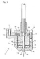
- the piercing unit X has a needle-like portion 10 for forming the instilling hole 6c, and a PTC heater 11 for heating the needle-like portion 10.
- the piercing unit X will be described in detail hereinafter.
- the needle-like portion 10 is shaped to be sharp-pointed having a diameter decreasing toward a tip end thereof, for example, to facilitate forming of the instilling hole 6c. More specifically, the diameter of the tip end is preferably within the range of 0.1mm through 0.8mm.
- the tip end projects outward through a bore 41 of a holder 40 housing the needle-like portion 10.
- the needle-like portion 10 extends through bores 51 and 61 formed, respectively, in a core 50 mounted in the holder 40 and in a cover 60 for sealing the holder 40.
- a flat-point hollow set screw 35 is provided in an intermediate position of the needle-like portion 10 to contact the inner wall of the bore 61.
- the cover 60 is fixed to the holder 40 by a cap bolt 33 through an insulating collar 32.
- the needle-like portion 10 is formed of SUS316, for example. It is desirable to apply a DLC (diamond-like carbon) coating to the surface at the tip end of the needle-like portion 10.
- the DLC coating can provide excellent surface smoothness and good friction and abrasion properties, and thus can be used effectively as a lubricating anti-abrasion film as well as aiming at an extended tool life. Further, the surface smoothness can improve peelability and mould-releasability of the resin, thereby to promote operational efficiency.
- the PTC heater 11 represents a heater using a PTC thermistor (Positive Temperature Coefficient Thermistor). It is preferably accommodated in the holder 40 to be close to the needle-like portion 10.
- the PTC thermistor comprises semiconductor ceramics containing barium titanate (BaTiO 3 ) as a main component, and may set Curie temperature (Tc) as desired by selecting a material composition. Having a nature of rapidly increasing the electric resistance when reaching Curie temperature, the PTC thermister is used as a fixed temperature heat generator.
- the PTC heater 11 may have any of various shapes including a disk shape, rectangular plate shape, ring shape, chip shape and the like.
- the present embodiment employs a ring-shaped thermistor having a bore 11a formed therein.
- the needle-like portion 10 extends through the bore 11a.
- the PTC heater 11 has a top surface contacting a top surface electrode 30 and a bottom surface contacting a bottom surface electrode 31, respectively, and is fixed to the core 50 through the top surface electrode 30 and a washer 34.
- a connector case 70 is attached to the holder 40 and the cover 60, and includes two lead wires and terminals 71 and 72 provided inside thereof. Electric connection can be established between the top surface electrode 30 and the terminal 71, and between the bottom surface electrode 31 and the terminal 72 through the lead wires, respectively.
- Each of the terminals 71 and 72 is connectable to an external power source.
- the PTC heater 11 is operable by rated voltages such as AC100V, AC200V, DC12V, DC24V and the like, for example.
- the PTC heater 11 is controlled preferably to 70 through 120°C.
- the temperature is controlled by supplying the PTC heater 11 with electricity from the external power source through the terminals 71 and 72, the lead wires, and the electrodes 30 and 31. More particularly, when both of the electrodes 30 and 31 are electrified, a voltage is applied to the PTC heater 11 contacting these electrodes at the top and bottom surfaces thereof. Then, the PTC heater 11 generates heat by itself due to Joule heat. When the heater exceeds Curie temperature (Tc), the value of resistance is logarithmically increased. Then, the electric current is reduced to restrain electric power and lower the heat-generating temperature. At this point, since the value of resistance is diminished, the electric current is increased. As a result, electric power is increased to raise the heat-generating temperature.
- the PTC heater 11 acts as a fixed temperature heat generator having a self-control function by repeating this cycle.
- the piercing unit X includes the needle-like portion 10 having the instilling hole 6c formed therein, and the PTC heater 11 acting as the fixed temperature heat generator.
- the PTC heater is supplied with electricity from the external power source through both of the electrodes 30 and 31 during a piercing operation for forming the instilling hole 6c.
- the PTC heater 11 generates heat which is conducted to the needle-like portion 10 arranged in the proximity of the heater. Since the PTC heater 11 is the fixed temperature heat generator having a self-control function for temperature, the heat generating temperature is substantially constant. Therefore, the heat amount conducted from the PTC heater 11 to the needle-like portion 10 is substantially constant as well, whereby the temperature of the needle-like portion 10 can be easily maintained constant.
- the present invention can provide the piercing unit X having the needle-like portion 10 that can easily maintain a proper temperature for forming the instilling hole 6c by controlling the PTC heater 11 to a proper temperature for forming the instilling hole 6c during a piercing operation to form the instilling hole 6c.
- this piercing unit X has the needle-like portion 10 acting as a heated needle whose temperature is easy to control, and thus can form instilling holes 6c having their opening area with less variations.
- the needle-like portion 10 can almost constantly maintain a proper temperature for forming the instilling hole 6c when the PTC heater 11 is controlled to a proper temperature for forming the instilling hole 6c.
- the PTC heater 11 is formed to surround the needle-like portion 10.
- the needle-like portion 10 extends through the bore 11a of the ring-shaped PTC heater 11, and the inner wall of the bore 11a surrounds the needle-like portion 10. In such a construction, the heat generated from the PTC heater 11 supplied with electricity can be conducted to the needle-like portion 10 efficiently.
- the PTC heater 11 may be 4.0mm in diameter while the bore 11a of the PTC heater 11 may be 4.3mm in diameter, for example.
- the PTC heater 11 is supplied with electricity from the external power source through both of the electrodes 30 and 31 during an operation to form the instilling hole 6c, the needle-like portion 10 is not electrified since the PTC heater 11 is not in direct contact with the needle-like portion 10. This is effective to prevent a failure of the container manufacturing apparatus caused by electric leakage, inadvertent variations of a predetermined temperature, and so on.
- the PTC heater 11 though not in direct contact with the needle-like portion 10, can heat the needle-like portion 10 since radiant heat of the PTC heater 11 under temperature control by electrification is conducted to the needle-like portion 10.
- the insulating collar 32, holder 40, core 50, connector case 70 and connector cover 73 are, preferably but not limitatively, made of polyether ether ketone (PEEK) having excellent heat-resistant property, strength and insulating property.
- PEEK polyether ether ketone
- the core 50 and connector cover 73 formed of the good heat-resisting material as above may have little chance of being deformed or broken, even if the needle-like portion 10 extending through the bores 51 and 61 formed in these components maintains heat enough to form the instilling hole 6c.
- the top surface electrode 30, bottom surface electrode 31, cap bolt 33, washer 34, flat-point hollow set screw 35, cover 60 and trussed screw 74 are, preferably but not limitatively, made of SUS304.
- the container manufacturing apparatus comprises various units usually required for manufacturing the eyedrops container, including a container body manufacturing unit for manufacturing the container body A loaded with the medical liquid in a sealed condition simultaneously with formation by blow molding or vacuum forming technique, a forming unit having an instilling opening forming device and the piercing unit X noted above for forming an instilling opening 6a in the container body A, a transport and supply unit for transporting the container body A made by blow molding or vacuum forming technique to the forming unit, a delivery unit for transporting the container body A having the instilling hole 6c formed therein by the piercing unit X to a location of the process for labeling and packaging the container body A, and so on.
- a container body manufacturing unit for manufacturing the container body A loaded with the medical liquid in a sealed condition simultaneously with formation by blow molding or vacuum forming technique
- a forming unit having an instilling opening forming device and the piercing unit X noted above for forming an instilling opening 6a in the container body A
- the thermoplastic material constituting the container body A may be any of polyethylene, polyethylene-polypropylene, polypropylene, polyethylene-terephthalate, polycarbonate and so on.
- the container body A made of polyethylene will be described.
- the container body A is manufactured by blow molding or vacuum forming technique in the container body manufacturing unit noted above.
- the blow molding or vacuum forming can be performed by a general process.
- the formed container body A is transported to the forming unit by the transport and supply unit.
- the instilling opening 6a (see Fig. 1) is formed in the container body A by the instilling opening forming unit. More particularly, as shown in Fig. 3(a), the instilling tube 6 forming the tip end of the container body A is heated in part to room temperature or 70°C through 150°C by a first heating device C such as hot air, a halogen lamp, laser beam or the like.
- a preferred heating temperature depends on the material or shape of the container body A, but may be selected so that the tip end of the container body A is somewhat softened.
- a convex mold 20 acting as the instilling opening forming unit is pressed in an axial direction Y of the container to the container body A before cooling of the instilling tube 6 of the container body A heated by the first heating device C.
- a bottomed conical recess 6b is formed in the instilling tube 6 of the container body A to have a larger inner diameter toward the instilling opening 6a.
- the convex mold 20 includes a mounting shaft 20A defining, at a distal end thereof, a conical molding projection 20B for forming the bottomed conical recess 6b, and a bowl-shaped (bell-shaped) molding surface 20C for forming an outer periphery of the instilling tube 6 of the container body A.
- the recess 6b has a depth in a range of 2 through 7mm, preferably in a range of 5 through 7mm, and most preferably 6mm.
- the opening diameter (mouth diameter) of the instilling opening 6a is adjusted within a range of 2.0 through 4.0mm depending on the liquidity of the medical liquid (surface tension and viscosity). In order to fix a drop amount (to be adjusted within a range of 25 through 50 ⁇ L per drop depending on purpose), the diameter of the instilling opening 6a is reduced for a liquid of high surface tension while the diameter of the instilling opening 6a is increased for a liquid of low surface tension.
- the instilling hole 6c is formed in the container body A by the piercing unit X.
- the piercing unit X is pressed to a middle portion of the bottom of the recess 6b formed in the instilling tube 6 of the container body A from the axial direction Y of the container body, thereby to form the instilling hole 6c.
- the PTC heater 11 is supplied with electricity from the external power source to generate heat which is conducted to the needle-like portion 10 adjacent thereto.
- the PTC heater 11 is heated to each of the temperatures shown in Table 1 below, for example. Since the temperature of the heat generated by the PTC heater 11 acting as the fixed temperature heat generator is substantially constant, the heat amount conducted form the PTC heater 11 to the needle-like portion 10 is also substantially constant. The temperature of the needle-like portion 10 is maintained constant around each of the temperature.
- the instilling holes 6c are formed at the respective temperatures.
- the instilling hole 6c is formed using the needle-like portion 10 of which the diameter of the tip end is, for example, within a range of 0.1 through 0.8mm.
- the smaller diameter of the needle-like portion is the more preferable, and the most preferable size is approximately 0.2mm in diameter.
- the needle having a range of 0.4 through 0.6mm in diameter is actually used.
- the processed container body A having the instilling hole 6c formed therein is labeled and packaged to eventually manufacture the eyedrops container.
- oblateness was measured. The measurement was performed by measuring oblateness of the instilling holes 6c formed in the temperatures shown in Table 1, respectively, when the PTC heater 11 was not electrified (at room temperature), and when the PTC heater 11 was heated to temperatures in the range of 30 through 140°C as shown in Table 1, respectively. Ten instilling holes 6c were formed at each temperature and the oblateness thereof was measured. Average values of oblateness in the respective temperatures are shown in Table 1. It should be noted that the oblateness represents values obtained by (shorter diameter/longer diameter) in the instilling hole 6c x 100.
- the results prove that good results of oblateness of 70 or more are obtained when the PTC heater 11 is heated to 70°C or higher. It has also turned out that the resin is sometimes hard to peel off from the tip end of the needle-like portion 10 when the heating temperature is 130°C or higher.
- the heating temperature of the PTC heater 11 is preferably in the range of 70 through 120°C. Further, the range of 100 through 120°C is most preferable in view of the obtained values of oblateness.
- the container manufacturing apparatus may be used for the purpose of piercing the eyedrops container mainly for medical use to form the instilling hole through which the medical liquid is discharged, for example.
Landscapes
- Engineering & Computer Science (AREA)
- Health & Medical Sciences (AREA)
- Mechanical Engineering (AREA)
- Life Sciences & Earth Sciences (AREA)
- Heart & Thoracic Surgery (AREA)
- Forests & Forestry (AREA)
- Ophthalmology & Optometry (AREA)
- Biomedical Technology (AREA)
- Ceramic Engineering (AREA)
- Vascular Medicine (AREA)
- Animal Behavior & Ethology (AREA)
- General Health & Medical Sciences (AREA)
- Public Health (AREA)
- Veterinary Medicine (AREA)
- Medical Preparation Storing Or Oral Administration Devices (AREA)
- Containers And Packaging Bodies Having A Special Means To Remove Contents (AREA)
- Closures For Containers (AREA)
Abstract
A container manufacturing apparatus for manufacturing a container body made of a thermoplastic material having a liquid storage portion for containing chemical liquid therein and an instilling hole for controlling a drop amount of discharged chemical liquid to be a predetermined amount, comprising a piercing unit X for piercing the container body to form the instilling hole therein, wherein the piercing unit X includes a needle-like portion 10 for forming the instilling hole, and a PTC heater 11 for heating the needle-like portion 10.
Description
- The present invention relates to a container manufacturing apparatus for manufacturing a container body made of a thermoplastic material having a liquid storage portion for containing liquid therein and an instilling hole for controlling a drop amount of discharged liquid to be a predetermined amount, the apparatus comprising a piercing unit for piercing the container body to form the instilling hole therein.
- It is required in medical eyedrops that a drop amount be controlled to be a predetermined amount. In order to perform such control, an eyedrops container provided with an inner plug forming an instilling hole therein is in wide use.
On the other hand, an integral molding type eyedrops container dispensing with the inner plug and having a container body integrally formed with the instilling hole has been known.
In the integral molding type eyedrops container, the container body is made of a thermoplastic material and loaded with liquid in a sealed condition simultaneously with blow molding or vacuum forming (what is called a bottle pack container body). The container body includes a male screw portion formed on an outer periphery of a tip end thereof. A cap is removably screwed on the male screw portion, the cap having a needle-like projection (piercing member) integrally formed therewith for piercing the tip end of the container body to form the instilling hole. The instilling hole is formed by the needle-like projection of the cap piercing the tip end of the container body when the cap is screwed in a fastening direction one step deeper than a normal stop position of the cap. - In such an eyedrops container, since the instilling hole is formed while the needle-like projection of the cap is piercing the tip end of the container body, the shape and size of the instilling hole could become uneven unless the amount of operation is adequate in screwing the cap in the fastening direction from the normal stop position. This may incur the possibility of varying the drop amount of liquid discharged from the container body.
On the other hand, when the cap is screwed excessively in the fastening direction from the normal stop position after the instilling hole is formed in the tip end of the container body, the instilling hole is expanded by the needle-like projection of the cap every time an excessive fastening operation is executed. This may lead to a possibility of gradually increasing the drop amount of liquid discharged from the container body. - In order to overcome these drawbacks, a container is known in which the instilling hole is formed by a method of piercing the tip end of an instilling tube with a needle-like mold in manufacturing the container body without using the needle-like projection provided on the cap.
For instance,Patent Document 1 discloses a method using a needle-like mold under a room temperature condition or a heated temperature condition, whilePatent Document 2 discloses a method of using a heated needle (needle-like mold). - Patent Document 1: JP Patent Publication "Kokai" No. 2001-120639 (see paragraph 0029)
- Patent Document 2: JP U.M. Publication No. S35-10375 (see
page 1 and Fig. 3) - As noted above, when the needle-like projection of the cap acting as an unheated needle is used in forming an instilling hole, variations occur in an opening area of the instilling hole, or the instilling hole may be shaped like a slit, i.e. a disadvantage of increased oblateness of the area of the instilling hole.
- In view of this, the needle-like mold heated by heating means such as high frequency induction heating technique, a halogen lamp, hot air or the like as disclosed in
Patent Document 1 is used, or the needle-like mold heated by flames as disclosed inPatent Document 2 is used, to form the instilling hole. As a result, instilling holes of generally uniform size are formed corresponding to the diameter of the needle. - However, it is difficult to control the temperature of the needle tip by the high frequency induction heating technique, halogen lamp, hot air, flames or the like as described above. In other words, there is a problem of difficulty in determining a proper temperature for the needle tip to form the instilling hole.
- Therefore, the object of the present invention is to provide a container manufacturing apparatus including a piercing unit for readily controlling temperature, and capable of forming instilling holes having an opening area with less variations and a shape with reduced oblateness and close to a circle.
- In order to fulfill the above-noted object, a first characteristic feature of a container manufacturing apparatus according to the present invention lies in the apparatus for manufacturing a container body made of a thermoplastic material having a liquid storage portion for containing liquid therein and an instilling hole for controlling a drop amount of discharged liquid to be a predetermined amount, comprising a piercing unit for piercing the container body to form the instilling hole therein, wherein the piercing unit includes a needle-like portion for forming the instilling hole, and a PTC heater for heating the needle-like portion.
- The PTC heater generates heat by itself due to Joule heat when supplied with electricity through electrodes. The resistance is increased logarithmically when temperature exceeds Curie temperature (Tc). Then, the heat generating temperature is reduced since the electric current diminishes to restrain electric power. At this time, resistance is reduced and thus the electric current is increased. As a result, the electric power is increased to raise the heat generating temperature. By repeating this cycle, the PTC heater acts as a fixed temperature heat generator having a self-control function.
As the needle-like portion is arranged in the proximity of the PTC heater, the heat is conducted from the self-heated PTC heater to the needle-like portion.
It should be noted that the heat generating temperature is substantially constant because the PTC heater is the fixed temperature heat generator having a self-control function for temperature. In other words, the heat amount conducted from the PTC heater to the needle-like portion is considered substantially constant as well. Thus, the temperature of the needle-like portion can easily be maintained constant. - Hence, the container manufacturing apparatus defined in the first characteristic feature of the present invention can provide the piercing unit having the needle-like portion for easily maintaining a proper temperature for forming the instilling hole by controlling the PTC heater at a proper temperature for forming the instilling hole.
Since this piercing unit includes the needle-like portion acting as a heated needle whose temperature can be controlled easily, it is possible to form the instilling hole having an opening area with less variations and a shape with reduced oblateness that is close to a circle. The needle-like portion may maintain the proper temperature almost constantly for forming the instilling hole when the PTC heater is controlled to the proper temperature for forming the instilling hole. - A second characteristic feature of a container manufacturing apparatus according to the present invention lies in that the PTC heater surrounds the needle-like portion.
- According to the container manufacturing apparatus defined in the second characteristic feature of the present invention, the heat of the PTC heater generated by electrification is efficiently conducted to the needle-like portion.
- A third characteristic feature of a container manufacturing apparatus according to the present invention lies in that the PTC heater is arranged not to contact the needle-like portion directly.
- According to the container manufacturing apparatus defined in the third characteristic feature of the present invention, the needle-like portion is not electrified even if the PTC heater is electrified because the PTC heater is not in direct contact with the needle-like portion. This is effective to prevent a failure of the container manufacturing apparatus caused by electric leakage, inadvertent variations of a predetermined temperature, and so on.
- An embodiment of the present invention will be described hereinafter with reference to the accompanying drawings.
A container manufacturing apparatus according to the present invention can be used for the purpose of piercing an eyedrops container mainly for medical use to form an instilling hole through which medical liquid is discharged, for example. - As shown in Fig. 1, the eyedrops container comprises a container body A made of a flexible thermoplastic material and filled with a predetermined amount of medical liquid simultaneously with blow molding or vacuum forming, and a cap B removably screwed to a
male screw portion 5a formed on an outer peripheral surface of a threadedtube 5 of the container body A.
The container body A includes aliquid storage portion 7 for containing the liquid therein, acircular bottom 1 curved inwardly, abarrel 2 in the form of a hollow cylinder continuous with a periphery of the bottom, acylindrical neck portion 3 formed continuous from ashoulder portion 2a of thebarrel 2, an annularstepped portion 4 bulging radially outwardly from an upper position of theneck portion 3, the threadedtube 5 with themale screw portion 5a continuous upward from the stepped portion, and aninstilling tube 6 continuous upward from the threaded tube.
Theinstilling tube 6 has aninstilling hole 6c for controlling a drop amount of the liquid to be discharged to be a predetermined amount. - The container manufacturing apparatus includes a piercing unit for forming the
instilling hole 6c in manufacturing the container body A.
As shown in Fig. 2, the piercing unit X has a needle-like portion 10 for forming theinstilling hole 6c, and aPTC heater 11 for heating the needle-like portion 10. The piercing unit X will be described in detail hereinafter. - The needle-
like portion 10 is shaped to be sharp-pointed having a diameter decreasing toward a tip end thereof, for example, to facilitate forming of theinstilling hole 6c. More specifically, the diameter of the tip end is preferably within the range of 0.1mm through 0.8mm. The tip end projects outward through abore 41 of aholder 40 housing the needle-like portion 10.
The needle-like portion 10 extends throughbores core 50 mounted in theholder 40 and in acover 60 for sealing theholder 40. A flat-pointhollow set screw 35 is provided in an intermediate position of the needle-like portion 10 to contact the inner wall of thebore 61. Thecover 60 is fixed to theholder 40 by acap bolt 33 through aninsulating collar 32. - The needle-
like portion 10 is formed of SUS316, for example. It is desirable to apply a DLC (diamond-like carbon) coating to the surface at the tip end of the needle-like portion 10.
The DLC coating can provide excellent surface smoothness and good friction and abrasion properties, and thus can be used effectively as a lubricating anti-abrasion film as well as aiming at an extended tool life. Further, the surface smoothness can improve peelability and mould-releasability of the resin, thereby to promote operational efficiency. - The
PTC heater 11 represents a heater using a PTC thermistor (Positive Temperature Coefficient Thermistor). It is preferably accommodated in theholder 40 to be close to the needle-like portion 10.
The PTC thermistor comprises semiconductor ceramics containing barium titanate (BaTiO3) as a main component, and may set Curie temperature (Tc) as desired by selecting a material composition. Having a nature of rapidly increasing the electric resistance when reaching Curie temperature, the PTC thermister is used as a fixed temperature heat generator. - The
PTC heater 11 may have any of various shapes including a disk shape, rectangular plate shape, ring shape, chip shape and the like. The present embodiment employs a ring-shaped thermistor having abore 11a formed therein. The needle-like portion 10 extends through thebore 11a. - The
PTC heater 11 has a top surface contacting atop surface electrode 30 and a bottom surface contacting abottom surface electrode 31, respectively, and is fixed to the core 50 through thetop surface electrode 30 and awasher 34.
Aconnector case 70 is attached to theholder 40 and thecover 60, and includes two lead wires andterminals top surface electrode 30 and the terminal 71, and between thebottom surface electrode 31 and the terminal 72 through the lead wires, respectively. Each of theterminals
ThePTC heater 11 is operable by rated voltages such as AC100V, AC200V, DC12V, DC24V and the like, for example. - The
PTC heater 11 is controlled preferably to 70 through 120°C. The temperature is controlled by supplying thePTC heater 11 with electricity from the external power source through theterminals electrodes electrodes PTC heater 11 contacting these electrodes at the top and bottom surfaces thereof. Then, thePTC heater 11 generates heat by itself due to Joule heat. When the heater exceeds Curie temperature (Tc), the value of resistance is logarithmically increased. Then, the electric current is reduced to restrain electric power and lower the heat-generating temperature. At this point, since the value of resistance is diminished, the electric current is increased. As a result, electric power is increased to raise the heat-generating temperature. ThePTC heater 11 acts as a fixed temperature heat generator having a self-control function by repeating this cycle. - Thus, the piercing unit X includes the needle-
like portion 10 having the instillinghole 6c formed therein, and thePTC heater 11 acting as the fixed temperature heat generator.
As noted above, the PTC heater is supplied with electricity from the external power source through both of theelectrodes hole 6c. At this time, thePTC heater 11 generates heat which is conducted to the needle-like portion 10 arranged in the proximity of the heater.
Since thePTC heater 11 is the fixed temperature heat generator having a self-control function for temperature, the heat generating temperature is substantially constant. Therefore, the heat amount conducted from thePTC heater 11 to the needle-like portion 10 is substantially constant as well, whereby the temperature of the needle-like portion 10 can be easily maintained constant.
Thus, the present invention can provide the piercing unit X having the needle-like portion 10 that can easily maintain a proper temperature for forming the instillinghole 6c by controlling thePTC heater 11 to a proper temperature for forming the instillinghole 6c during a piercing operation to form the instillinghole 6c.
More particularly, this piercing unit X has the needle-like portion 10 acting as a heated needle whose temperature is easy to control, and thus can form instillingholes 6c having their opening area with less variations. The needle-like portion 10 can almost constantly maintain a proper temperature for forming the instillinghole 6c when thePTC heater 11 is controlled to a proper temperature for forming the instillinghole 6c. - It is preferable that the
PTC heater 11 is formed to surround the needle-like portion 10.
In the present embodiment, the needle-like portion 10 extends through thebore 11a of the ring-shapedPTC heater 11, and the inner wall of thebore 11a surrounds the needle-like portion 10. In such a construction, the heat generated from thePTC heater 11 supplied with electricity can be conducted to the needle-like portion 10 efficiently. - It is also preferable to provide the
PTC heater 11 so as not to directly contact the needle-like portion 10.
In this case, the needle-like portion10 may be 4.0mm in diameter while thebore 11a of thePTC heater 11 may be 4.3mm in diameter, for example.
Although thePTC heater 11 is supplied with electricity from the external power source through both of theelectrodes hole 6c, the needle-like portion 10 is not electrified since thePTC heater 11 is not in direct contact with the needle-like portion 10. This is effective to prevent a failure of the container manufacturing apparatus caused by electric leakage, inadvertent variations of a predetermined temperature, and so on. - On the other hand, the
PTC heater 11, though not in direct contact with the needle-like portion 10, can heat the needle-like portion 10 since radiant heat of thePTC heater 11 under temperature control by electrification is conducted to the needle-like portion 10. - Among the components noted above, the insulating
collar 32,holder 40,core 50,connector case 70 and connector cover 73 are, preferably but not limitatively, made of polyether ether ketone (PEEK) having excellent heat-resistant property, strength and insulating property.
Thecore 50 and connector cover 73 formed of the good heat-resisting material as above may have little chance of being deformed or broken, even if the needle-like portion 10 extending through thebores hole 6c.
It should be noted that thetop surface electrode 30,bottom surface electrode 31,cap bolt 33,washer 34, flat-pointhollow set screw 35,cover 60 and trussed screw 74 are, preferably but not limitatively, made of SUS304. - The container manufacturing apparatus comprises various units usually required for manufacturing the eyedrops container, including a container body manufacturing unit for manufacturing the container body A loaded with the medical liquid in a sealed condition simultaneously with formation by blow molding or vacuum forming technique, a forming unit having an instilling opening forming device and the piercing unit X noted above for forming an instilling
opening 6a in the container body A, a transport and supply unit for transporting the container body A made by blow molding or vacuum forming technique to the forming unit, a delivery unit for transporting the container body A having the instillinghole 6c formed therein by the piercing unit X to a location of the process for labeling and packaging the container body A, and so on. - A process for piercing the above-noted eyedrops container to form the instilling
hole 6c therein using the container manufacturing apparatus according to the present invention will be described hereinafter (see Fig. 3). - The thermoplastic material constituting the container body A may be any of polyethylene, polyethylene-polypropylene, polypropylene, polyethylene-terephthalate, polycarbonate and so on. In this embodiment, the container body A made of polyethylene will be described.
- The container body A is manufactured by blow molding or vacuum forming technique in the container body manufacturing unit noted above. The blow molding or vacuum forming can be performed by a general process. The formed container body A is transported to the forming unit by the transport and supply unit.
- In the forming unit, the instilling
opening 6a (see Fig. 1) is formed in the container body A by the instilling opening forming unit.
More particularly, as shown in Fig. 3(a), the instillingtube 6 forming the tip end of the container body A is heated in part to room temperature or 70°C through 150°C by a first heating device C such as hot air, a halogen lamp, laser beam or the like. A preferred heating temperature depends on the material or shape of the container body A, but may be selected so that the tip end of the container body A is somewhat softened. - Next, as shown in Fig. 3(b), a
convex mold 20 acting as the instilling opening forming unit is pressed in an axial direction Y of the container to the container body A before cooling of the instillingtube 6 of the container body A heated by the first heating device C. Thus, a bottomedconical recess 6b (see Fig. 1) is formed in the instillingtube 6 of the container body A to have a larger inner diameter toward the instillingopening 6a.
Theconvex mold 20 includes a mountingshaft 20A defining, at a distal end thereof, aconical molding projection 20B for forming the bottomedconical recess 6b, and a bowl-shaped (bell-shaped)molding surface 20C for forming an outer periphery of the instillingtube 6 of the container body A. - The
recess 6b has a depth in a range of 2 through 7mm, preferably in a range of 5 through 7mm, and most preferably 6mm. The opening diameter (mouth diameter) of the instillingopening 6a is adjusted within a range of 2.0 through 4.0mm depending on the liquidity of the medical liquid (surface tension and viscosity). In order to fix a drop amount (to be adjusted within a range of 25 through 50µL per drop depending on purpose), the diameter of the instillingopening 6a is reduced for a liquid of high surface tension while the diameter of the instillingopening 6a is increased for a liquid of low surface tension. - After the instilling
opening 6a is formed in the container body A, the instillinghole 6c is formed in the container body A by the piercing unit X. - More particularly, as shown in Figs. 3(c) and (d), the piercing unit X is pressed to a middle portion of the bottom of the
recess 6b formed in the instillingtube 6 of the container body A from the axial direction Y of the container body, thereby to form the instillinghole 6c.
At this time, thePTC heater 11 is supplied with electricity from the external power source to generate heat which is conducted to the needle-like portion 10 adjacent thereto. ThePTC heater 11 is heated to each of the temperatures shown in Table 1 below, for example. Since the temperature of the heat generated by thePTC heater 11 acting as the fixed temperature heat generator is substantially constant, the heat amount conducted form thePTC heater 11 to the needle-like portion 10 is also substantially constant. The temperature of the needle-like portion 10 is maintained constant around each of the temperature. The instillingholes 6c are formed at the respective temperatures. - The instilling
hole 6c is formed using the needle-like portion 10 of which the diameter of the tip end is, for example, within a range of 0.1 through 0.8mm. The smaller diameter of the needle-like portion is the more preferable, and the most preferable size is approximately 0.2mm in diameter. On the other hand, since it is technically hard to form a needle with an extremely small diameter, the needle having a range of 0.4 through 0.6mm in diameter is actually used. - The processed container body A having the instilling
hole 6c formed therein is labeled and packaged to eventually manufacture the eyedrops container. - In order to evaluate the instilling
hole 6c of the eyedrops container formed in this way, oblateness was measured. The measurement was performed by measuring oblateness of the instillingholes 6c formed in the temperatures shown in Table 1, respectively, when thePTC heater 11 was not electrified (at room temperature), and when thePTC heater 11 was heated to temperatures in the range of 30 through 140°C as shown in Table 1, respectively. Ten instillingholes 6c were formed at each temperature and the oblateness thereof was measured. Average values of oblateness in the respective temperatures are shown in Table 1.
It should be noted that the oblateness represents values obtained by (shorter diameter/longer diameter) in the instillinghole 6c x 100. -

- The results prove that good results of oblateness of 70 or more are obtained when the
PTC heater 11 is heated to 70°C or higher.
It has also turned out that the resin is sometimes hard to peel off from the tip end of the needle-like portion 10 when the heating temperature is 130°C or higher. Thus, the heating temperature of thePTC heater 11 is preferably in the range of 70 through 120°C. Further, the range of 100 through 120°C is most preferable in view of the obtained values of oblateness. - The container manufacturing apparatus according to the present invention may be used for the purpose of piercing the eyedrops container mainly for medical use to form the instilling hole through which the medical liquid is discharged, for example.
-
- [Fig. 1] Schematic view of an eyedrops container.
- [Fig. 2] Schematic view of a piercing unit of a container manufacturing apparatus according to the present invention.
- [Fig. 3] Schematic view of a process of piercing the eyedrops container to form an instilling hole using the container manufacturing apparatus according to the present invention.
-
- 6c
- instilling hole
- 7
- liquid storage portion
- 10
- needle-like portion
- 11
- PTC heater
- A
- container body
- X
- piercing unit
Claims (3)
- A container manufacturing apparatus for manufacturing a container body made of a thermoplastic material having a liquid storage portion for containing liquid therein and an instilling hole for controlling a drop amount of discharged liquid to be a predetermined amount, comprising a piercing unit for piercing the container body to form the instilling hole therein,
wherein the piercing unit includes a needle-like portion for forming the instilling hole, and a PTC heater for heating the needle-like portion. - A container manufacturing apparatus as claimed in Claim 1, wherein the PTC heater surrounds the needle-like portion.
- A container manufacturing apparatus as claimed in Claim 1 or 2, wherein the PTC heater is arranged not to contact the needle-like portion directly.
Applications Claiming Priority (2)
| Application Number | Priority Date | Filing Date | Title |
|---|---|---|---|
| JP2003348103 | 2003-10-07 | ||
| PCT/JP2004/014818 WO2005034836A1 (en) | 2003-10-07 | 2004-10-07 | Container manufacturing device |
Publications (2)
| Publication Number | Publication Date |
|---|---|
| EP1679057A1 true EP1679057A1 (en) | 2006-07-12 |
| EP1679057A4 EP1679057A4 (en) | 2008-12-03 |
Family
ID=34430952
Family Applications (1)
| Application Number | Title | Priority Date | Filing Date |
|---|---|---|---|
| EP04792116A Withdrawn EP1679057A4 (en) | 2003-10-07 | 2004-10-07 | Container manufacturing device |
Country Status (5)
| Country | Link |
|---|---|
| US (1) | US20070164012A1 (en) |
| EP (1) | EP1679057A4 (en) |
| CN (1) | CN100435768C (en) |
| TW (1) | TW200513254A (en) |
| WO (1) | WO2005034836A1 (en) |
Cited By (1)
| Publication number | Priority date | Publication date | Assignee | Title |
|---|---|---|---|---|
| WO2009144559A3 (en) * | 2008-05-30 | 2010-08-12 | Lameplast S.P.A. | Process for the manufacture of single-dose phials for fluid products of the medical, pharmaceutical, cosmetic type or the like, and a phial thus obtainable |
Families Citing this family (2)
| Publication number | Priority date | Publication date | Assignee | Title |
|---|---|---|---|---|
| US20140350492A1 (en) * | 2013-05-26 | 2014-11-27 | Ever Rojas Escalante | Eyedrop dispenser |
| CN105459211B (en) * | 2015-12-17 | 2017-02-08 | 贵州顺安机电设备有限公司 | Machining cutting device for concentric boiling plate |
Family Cites Families (8)
| Publication number | Priority date | Publication date | Assignee | Title |
|---|---|---|---|---|
| US3767597A (en) * | 1970-07-15 | 1973-10-23 | Matsushita Electric Industrial Co Ltd | High temperature thermistor composition |
| US4034207A (en) * | 1976-01-23 | 1977-07-05 | Murata Manufacturing Co., Ltd. | Positive temperature coefficient semiconductor heating element |
| US4501951A (en) * | 1982-08-16 | 1985-02-26 | E. I. Du Pont De Nemours And Company | Electric heating element for sterilely cutting and welding together thermoplastic tubes |
| GB9213265D0 (en) * | 1992-06-23 | 1992-08-05 | Fra Mo Snc | Sheet perforation |
| JP3694446B2 (en) * | 1999-08-17 | 2005-09-14 | 参天製薬株式会社 | Open eye drop container and manufacturing method thereof |
| KR100544221B1 (en) * | 1999-08-17 | 2006-01-23 | 산텐 세이야꾸 가부시키가이샤 | Method of manufacturing open instillation container |
| CN2408641Y (en) * | 2000-01-13 | 2000-11-29 | 上海科达电子陶瓷有限公司 | Automatic thermostat electric heater |
| JP2003173858A (en) * | 2001-12-06 | 2003-06-20 | Mitsumi Electric Co Ltd | Heat dissipation device using PTC heater |
-
2004
- 2004-10-06 TW TW093130277A patent/TW200513254A/en unknown
- 2004-10-07 CN CNB2004800295411A patent/CN100435768C/en not_active Expired - Fee Related
- 2004-10-07 US US10/574,753 patent/US20070164012A1/en not_active Abandoned
- 2004-10-07 EP EP04792116A patent/EP1679057A4/en not_active Withdrawn
- 2004-10-07 WO PCT/JP2004/014818 patent/WO2005034836A1/en not_active Ceased
Non-Patent Citations (2)
| Title |
|---|
| No further relevant documents disclosed * |
| See also references of WO2005034836A1 * |
Cited By (1)
| Publication number | Priority date | Publication date | Assignee | Title |
|---|---|---|---|---|
| WO2009144559A3 (en) * | 2008-05-30 | 2010-08-12 | Lameplast S.P.A. | Process for the manufacture of single-dose phials for fluid products of the medical, pharmaceutical, cosmetic type or the like, and a phial thus obtainable |
Also Published As
| Publication number | Publication date |
|---|---|
| EP1679057A4 (en) | 2008-12-03 |
| CN1863496A (en) | 2006-11-15 |
| TW200513254A (en) | 2005-04-16 |
| CN100435768C (en) | 2008-11-26 |
| WO2005034836A1 (en) | 2005-04-21 |
| US20070164012A1 (en) | 2007-07-19 |
Similar Documents
| Publication | Publication Date | Title |
|---|---|---|
| CN102026569B (en) | Apparatus for heating fluids in containers | |
| US12098866B2 (en) | Tubular thick film heater protection apparatus and tubular thick film heater | |
| JP7719307B2 (en) | Atomizers and electronic atomizers | |
| KR20180121525A (en) | An E-belling device cartridge having an internal infrared sensor | |
| NZ242552A (en) | Heat sensitive chemical dispenser; variable separation between heater and dispenser | |
| CA2654790A1 (en) | Indirectly heated capillary aerosol generator | |
| WO2012032149A1 (en) | Heating application device for a cosmetic product | |
| CN110997161B (en) | Hot glue sticking equipment with hot glue pen | |
| KR20210124459A (en) | aerosol delivery device | |
| US20070164012A1 (en) | Container manufacturing device | |
| CN111479479B (en) | Cartridges and e-vaping devices | |
| US8338808B2 (en) | Ultraviolet radiation lamp and source module and treatment system containing same | |
| JP4549148B2 (en) | Container manufacturing equipment | |
| US3757085A (en) | Removable top with a heating element for a vacuum insulated bottle | |
| CN102512085B (en) | Embedded milk heater and feeding bottle | |
| US3973100A (en) | Self-limiting electric hair curler heater | |
| JP7296057B2 (en) | Xenon flash lamp irradiation equipment for container sterilization | |
| WO2024103603A1 (en) | Baby bottle warmer | |
| RU2854567C2 (en) | Aerosol-generating device, heating unit therefor and method of its assembly, and aerosol-generating system | |
| CN217479027U (en) | Sealing assembly and sealing machine | |
| EP4728915A1 (en) | Aerosol-generating device and control method therefor | |
| EP0790027A1 (en) | Electric heat insulating pot | |
| KR100525308B1 (en) | Heating Device | |
| KR20170052915A (en) | Method of manufacturing pyrexia wire and a pyrexia wire produced by this method | |
| JPH0935878A (en) | Abnormal overheat preventing device for fluorescent lamp |
Legal Events
| Date | Code | Title | Description |
|---|---|---|---|
| PUAI | Public reference made under article 153(3) epc to a published international application that has entered the european phase |
Free format text: ORIGINAL CODE: 0009012 |
|
| 17P | Request for examination filed |
Effective date: 20060406 |
|
| AK | Designated contracting states |
Kind code of ref document: A1 Designated state(s): AT BE BG CH CY CZ DE DK EE ES FI FR GB GR HU IE IT LI LU MC NL PL PT RO SE SI SK TR |
|
| DAX | Request for extension of the european patent (deleted) | ||
| A4 | Supplementary search report drawn up and despatched |
Effective date: 20081103 |
|
| GRAP | Despatch of communication of intention to grant a patent |
Free format text: ORIGINAL CODE: EPIDOSNIGR1 |
|
| STAA | Information on the status of an ep patent application or granted ep patent |
Free format text: STATUS: THE APPLICATION IS DEEMED TO BE WITHDRAWN |
|
| 18D | Application deemed to be withdrawn |
Effective date: 20091202 |