EP1678996A1 - Variety Locator - Google Patents
Variety Locator Download PDFInfo
- Publication number
- EP1678996A1 EP1678996A1 EP05112553A EP05112553A EP1678996A1 EP 1678996 A1 EP1678996 A1 EP 1678996A1 EP 05112553 A EP05112553 A EP 05112553A EP 05112553 A EP05112553 A EP 05112553A EP 1678996 A1 EP1678996 A1 EP 1678996A1
- Authority
- EP
- European Patent Office
- Prior art keywords
- input attribute
- zone
- geographic position
- crop
- machine
- Prior art date
- Legal status (The legal status is an assumption and is not a legal conclusion. Google has not performed a legal analysis and makes no representation as to the accuracy of the status listed.)
- Granted
Links
Images


Classifications
-
- A—HUMAN NECESSITIES
- A01—AGRICULTURE; FORESTRY; ANIMAL HUSBANDRY; HUNTING; TRAPPING; FISHING
- A01D—HARVESTING; MOWING
- A01D41/00—Combines, i.e. harvesters or mowers combined with threshing devices
- A01D41/12—Details of combines
- A01D41/127—Control or measuring arrangements specially adapted for combines
-
- A—HUMAN NECESSITIES
- A01—AGRICULTURE; FORESTRY; ANIMAL HUSBANDRY; HUNTING; TRAPPING; FISHING
- A01B—SOIL WORKING IN AGRICULTURE OR FORESTRY; PARTS, DETAILS, OR ACCESSORIES OF AGRICULTURAL MACHINES OR IMPLEMENTS, IN GENERAL
- A01B79/00—Methods for working soil
- A01B79/005—Precision agriculture
-
- Y—GENERAL TAGGING OF NEW TECHNOLOGICAL DEVELOPMENTS; GENERAL TAGGING OF CROSS-SECTIONAL TECHNOLOGIES SPANNING OVER SEVERAL SECTIONS OF THE IPC; TECHNICAL SUBJECTS COVERED BY FORMER USPC CROSS-REFERENCE ART COLLECTIONS [XRACs] AND DIGESTS
- Y10—TECHNICAL SUBJECTS COVERED BY FORMER USPC
- Y10S—TECHNICAL SUBJECTS COVERED BY FORMER USPC CROSS-REFERENCE ART COLLECTIONS [XRACs] AND DIGESTS
- Y10S111/00—Planting
- Y10S111/90—Methods of planting seeds and miscellaneous compositions
-
- Y—GENERAL TAGGING OF NEW TECHNOLOGICAL DEVELOPMENTS; GENERAL TAGGING OF CROSS-SECTIONAL TECHNOLOGIES SPANNING OVER SEVERAL SECTIONS OF THE IPC; TECHNICAL SUBJECTS COVERED BY FORMER USPC CROSS-REFERENCE ART COLLECTIONS [XRACs] AND DIGESTS
- Y10—TECHNICAL SUBJECTS COVERED BY FORMER USPC
- Y10S—TECHNICAL SUBJECTS COVERED BY FORMER USPC CROSS-REFERENCE ART COLLECTIONS [XRACs] AND DIGESTS
- Y10S111/00—Planting
- Y10S111/903—Monitor
Definitions
- the present invention generally relates to the field of planting and harvesting crops, and more particularly to a variety locator for utilizing information collected during the planting and growing phases of the crop production cycle for segregating the crop during harvesting.
- the present invention is directed to a system and method for providing an input attribute collected in a tillable area while harvesting a crop from the tillable area.
- the input attribute is collected before the crop is harvested, e.g. information collected during the planting and growing phases of the crop production cycle is input by an operator of a machine.
- a geographic position e.g., latitude and longitude
- the input attribute and the geographic position are transmitted from the machine to a central system, such as a personal desktop computer, a centrally located server, or the like.
- the input attribute is associated with a zone including the geographic position at which the input attribute was collected.
- the zone includes other geographic positions for which the same (or sufficiently similar) input attributes have been collected.
- the zone represents a geographic region in which the input attribute is applicable.
- the zone is stored along with its associated input attribute in a database, a linked list, or in another data format.
- the zone is stored as one or more grid cells.
- the zone is stored as a polygon.
- the measured position of the machine is compared with the stored zone. If the position of the machine is determined to be within the stored zone, the input attribute associated with the zone is supplied to the operator of the harvesting machine. For instance, if the position of the harvesting machine is within the bounds of a grid cell stored with the zone, the input attribute associated with the grid cell is supplied to the operator. Alternatively, if the position of the harvesting machine is within the exterior boundary of a polygon representing the stored zone, the input attribute associated with the stored zone is supplied to the operator of the machine.
- the input attribute in combination with the zone, may be utilized for segregating a harvested crop.
- a crop harvested from the tillable area may be segregated by harvesting only a portion of the crop located within a first zone, while harvesting another portion of the crop from another zone having a different input attribute, and keeping the harvested crop loads separated. In this manner, the harvested crop is segregated.
- an input attribute collected and associated with a zone may be further associated with a portion of the crop harvested from the zone for identification purposes.
- a positioning system, the collected input attribute, and the zone may be utilized for providing automated guidance to a harvesting machine for guiding the machine to harvest a desired portion of the crop disposed within a zone having a desired input attribute.
- the method 100 allows an operator to input desired information about the tillable area 200 in the form of the input attribute, such as identifying information collected during the planting and growing phases of the crop production cycle.
- the input attribute is collected before the crop is harvested.
- the input attribute describes a type of seed planted, while in other embodiments, the input attribute includes a variety of seed planted, a chemical treatment applied to the tillable area 200, a process performed upon the tillable area, and the like.
- the input attribute may include other descriptive information regarding the tillable area 200 as well, without departing from the scope and intent of the present invention. Further, it will be appreciated that a single input attribute may be utilized to describe a plurality of identifying information. For instance, a first numerical value is utilized to represent a first seed variety planted in combination with a specified fertilizer, while another numerical value is utilized to represent a second seed variety planted in combination with the same fertilizer.
- the input attribute is collected by a system 300 from an operator of a machine 302.
- the machine 302 may be a tractor or another machine utilized for applying materials to the tillable area 200.
- the input attribute is collected from the operator of the machine via a user interface 304.
- the operator of the machine 302 may specify a seed variety being planted via the user interface 304, such as inputting the seed variety via a touch screen, a keyboard, or a like input device.
- the input attribute is collected directly from the machine 302.
- the machine 302 may specify a chemical treatment being applied to the tillable area 200.
- a processing unit 306 including a data transfer mechanism 308 (e.g.
- a PC card may be in communication with the machine 302, for collecting information about the machine's activities in the tillable area 200.
- the machine 302 may be connected to the processing unit 306 and the PC card via a communication bus 310.
- the machine 302 may be connected to the data transfer mechanism 308 via a wireless link.
- the machine 302 may be connected to another machine 312, such as a farming implement for towing behind a tractor.
- the second machine 312 may communicate with the machine 302 via communication bus 310, a wireless link, or the like, for providing an input attribute to the processing unit 306.
- the second machine 312 may be in direct communication with the data transfer mechanism 308 via bus architecture, such as the communication bus 310, via a wireless link, and the like.
- a geographic position 202 occupied by the machine 302 is measured.
- the geographic position of the machine e.g., latitude and longitude
- a positioning system is utilized to measure the geographic position 202 of the machine 302 when the input attribute is collected.
- a positioning system receiver assembly receives positioning signals from a positioning system and generates positioning system based navigation information including position (e.g., latitude and longitude), course or heading, speed, time, and the like.
- the positioning system receiver assembly receives positioning signals from the Global Positioning System (GPS), a space-based radio-navigation system managed by the United States Air Force for the Government of the United States.
- GPS Global Positioning System
- the positioning system receiver assembly may alternately be adapted for use with other radio based navigation/global positioning systems such as the GLONASS Navigation Satellite System managed by the Russian Space Agency (RSA) for the Russian Federation.
- the positioning system receiver assembly may be capable of receiving and utilizing enhanced positioning information provided by differential GPS systems and wide area differential GPS (WADGPS) such as the STARFIRETM WDGPS system developed by John Deere and Company of Moline, Illinois, the Wide Area Augmentation System (WAAS) provided by the Federal Aviation Administration of the United States Government, or the like.
- WADGPS wide area differential GPS
- the positioning system receiver assembly may include, or be coupled to, a radio receiver for receiving differential error correction information.
- the input attribute and the geographic position 202 are transmitted from the machine 302 (i.e. from vehicle system 314) to a central system 316, such as a personal desktop computer, a centrally located server, or the like.
- a central system 316 such as a personal desktop computer, a centrally located server, or the like.
- the input attribute and the geographic position 202 are transmitted from the processing unit 306 of the vehicle system 314 to the central system 316 via a wireless connection, a communication bus, an Internet connection, an intranet connection, or the like, such as an Ethernet connection between data transfer mechanism 308 and data transfer mechanism 318.
- the input attribute and the geographic position 202 are transmitted to the central system after a portion of the tillable area 200 has been traversed by the machine 302, while in a further embodiment, each input attribute and geographic position 202 is transmitted to the central system 316 as it is collected. For example, in one specific embodiment, an operator traverses a portion of the tillable area 200 and then connects his vehicle system 314 to the central system 316 via an Ethernet connection between data transfer mechanisms 308 and 318, for transmitting the input attribute and the geographic position 202 from the processing unit 306 to the central system 316. In another embodiment, each input attribute and geographic position 202 is transmitted via a wireless connection between data transfer mechanisms 308 and 318.
- the input attribute is associated with a zone 204 including the geographic position 202 at which the input attribute was collected while traversing the tillable area 200.
- the zone 204 includes a plurality of geographic positions within the tillable area 202.
- the plurality of geographic positions included in the zone 204 includes geographic positions for which the same (or sufficiently similar) input attributes have been collected. For instance, each geographic position within the zone 204 is seeded with the same variety of seed. It should be noted that geographic positions within the zone 204 for which sufficiently similar input attributes have been collected may be grouped together utilizing the zone 204, e.g. each geographic position within the zone 204 is seeded with a differing variety of seed for the same crop.
- each geographic position within the zone 204 is seeded with the same variety of seed, but may be fertilized with a differing variety of fertilizer.
- the zone 204 represents a geographic region in which an input attribute associated with the zone 204 is applicable.
- the zone 204 is stored along with its associated input attribute.
- the zone 204 and the input attribute are stored in the memory of the central system 316.
- the zone 204 and the input attribute are stored in the memory of the vehicle system 314.
- the zone 204 and the input attribute may be stored in a database, a linked list, or in another data format as contemplated by one of skill in the art.
- the zone 204 is stored as one or more grid cells, in which case the input attribute is associated with a grid cell or a plurality of grid cells.
- the zone 204 is stored as a polygon and the input attribute is associated with the polygon.
- the polygon may describe a planar surface defined by one exterior boundary and zero or more interior boundaries, each interior boundary describing a portion of the zone not included in the polygon.
- the zone 204 may be stored in various ways without departing from the scope and intent of the present invention.
- a geographic position occupied by the machine 302 is measured (e.g., latitude and longitude).
- a positioning system receiver assembly receives positioning signals from a positioning system and generates positioning system based navigation information for the harvesting equipment, including geographic position (e.g., latitude and longitude), course or heading, speed, time, and the like.
- a positioning system is utilized to measure the geographic position of the machine 302
- a positioning system is utilized to measure the geographic position of another machine for harvesting the crop planted in the tillable area 200.
- the position of the machine measured at step 110 is compared with the zone 204 stored in step 108.
- the position of the machine measured at step 110 is compared with the zone 204 utilizing the processing unit 306 (or another processing unit). If the position of the machine is determined to be within the zone 204, the input attribute associated with the zone 204 is supplied to the operator of the machine via the user interface 304, at step 114. For instance, if the position of the machine is within the bounds of a grid cell stored with the zone 204, the input attribute associated with the grid cell is supplied to the operator via the user interface 304.
- the input attribute associated with the zone 204 is supplied to the operator of the machine via the user interface 304. More specifically, when a harvesting machine is located at position 202, the input attribute collected by the machine 302 at location 202 is supplied to the operator of the harvesting machine. Further, when the harvesting machine is located within the zone 204 associated with the input attribute collected at location 202, the input attribute is supplied to the operator of the harvesting machine.
- the input attribute in combination with the zone, may be utilized for segregating a harvested crop.
- a crop harvested from the tillable area 200 may be segregated by harvesting only a portion of the crop located within the zone 204, while harvesting another portion of the crop from another zone having a different input attribute, and keeping the harvested crop loads separated. In this manner, the harvested crop is segregated. This would be desirable for keeping different types of crops separate, e.g. crops fertilized with different materials, and the like.
- an input attribute collected and associated with a zone may be further associated with a portion of the crop harvested from the zone, such as for identification purposes.
- a crop harvested in zone 204 is associated with the input attribute collected at geographic position 202.
- a positioning system, the collected input attribute, and the zone may be utilized for providing automated guidance to a harvesting machine without departing from the scope of the present invention.
- an operator may specify a desired portion of the crop for harvesting within the tillable area 200, e.g. a portion of the crop disposed within the zone 204.
- a harvesting machine may utilize automated guidance functionality in combination with the positioning system for guiding the machine to harvest that portion of the crop disposed within the zone 204. It is contemplated that the utilization of other guidance techniques for segregating a harvested crop utilizing the input attribute and the zone 204 would not fall outside of the scope and spirit of the present invention.
- the methods disclosed may be implemented as sets of instructions or software readable by a device. Further, it is understood that the specific order or hierarchy of steps in the methods disclosed are examples of exemplary approaches. Based upon design preferences, it is understood that the specific order or hierarchy of steps in the method can be rearranged while remaining within the scope and spirit of the present invention.
- the accompanying method claims present elements of the various steps in a sample order, and are not necessarily meant to be limited to the specific order or hierarchy presented.
Landscapes
- Life Sciences & Earth Sciences (AREA)
- Environmental Sciences (AREA)
- Engineering & Computer Science (AREA)
- Mechanical Engineering (AREA)
- Soil Sciences (AREA)
- Management, Administration, Business Operations System, And Electronic Commerce (AREA)
- Guiding Agricultural Machines (AREA)
Abstract
measuring a first geographic position (202) for the machine (302);
associating the input attribute with a zone (204) including the first geographic position (202);
measuring a second geographic position while harvesting the crop from the tillable area (200);
comparing the second geographic position with the zone (204); providing the stored input attribute when the second geographic position is in the zone (204).
Description
- The present invention generally relates to the field of planting and harvesting crops, and more particularly to a variety locator for utilizing information collected during the planting and growing phases of the crop production cycle for segregating the crop during harvesting.
- Frequently, it is desirable to segregate a crop harvested from a tillable area. For instance, different geographical regions of the tillable area may be seeded with different varieties of seed. Alternatively, different geographical regions of the tillable area may be seeded with the same variety of seed, but may be fertilized with differing varieties of fertilizer. Thus, if portions of the crop are to be harvested and stored with like varieties, information about the crop collected during the planting and growing phases of the crop production cycle must be available during the harvest. A prior art method and system is described in EP 0 723 740 A, but not disclosing how the information about the crop on the field is provided.
- Thus, there exists a need for a system and method to provide real-time geographically referenced visibility of data collected during the planting and growing phases of the crop production cycle.
- Accordingly, the present invention is directed to a system and method for providing an input attribute collected in a tillable area while harvesting a crop from the tillable area. First, the input attribute is collected before the crop is harvested, e.g. information collected during the planting and growing phases of the crop production cycle is input by an operator of a machine. Then, a geographic position (e.g., latitude and longitude) occupied by the machine is measured utilizing a positioning system, preferably when the input attribute is collected The input attribute and the geographic position are transmitted from the machine to a central system, such as a personal desktop computer, a centrally located server, or the like. Next, the input attribute is associated with a zone including the geographic position at which the input attribute was collected. The zone includes other geographic positions for which the same (or sufficiently similar) input attributes have been collected. Thus, the zone represents a geographic region in which the input attribute is applicable.
- Next, the zone is stored along with its associated input attribute in a database, a linked list, or in another data format. In one embodiment, the zone is stored as one or more grid cells. In another embodiment, the zone is stored as a polygon. As the crop planted in the tillable area is harvested, a geographic position occupied by the harvesting machine is measured. Next, the measured position of the machine is compared with the stored zone. If the position of the machine is determined to be within the stored zone, the input attribute associated with the zone is supplied to the operator of the harvesting machine. For instance, if the position of the harvesting machine is within the bounds of a grid cell stored with the zone, the input attribute associated with the grid cell is supplied to the operator. Alternatively, if the position of the harvesting machine is within the exterior boundary of a polygon representing the stored zone, the input attribute associated with the stored zone is supplied to the operator of the machine.
- Thus, the input attribute, in combination with the zone, may be utilized for segregating a harvested crop. For instance, a crop harvested from the tillable area may be segregated by harvesting only a portion of the crop located within a first zone, while harvesting another portion of the crop from another zone having a different input attribute, and keeping the harvested crop loads separated. In this manner, the harvested crop is segregated. It will also be appreciated that an input attribute collected and associated with a zone may be further associated with a portion of the crop harvested from the zone for identification purposes. Further, a positioning system, the collected input attribute, and the zone may be utilized for providing automated guidance to a harvesting machine for guiding the machine to harvest a desired portion of the crop disposed within a zone having a desired input attribute.
- It is to be understood that both the foregoing general description and the following detailed description are exemplary and explanatory only and are not necessarily restrictive of the invention as claimed. The accompanying drawings, which are incorporated in and constitute a part of the specification, illustrate an embodiment of the invention and together with the general description, serve to explain the principles of the invention.
- The numerous advantages of the present invention may be better understood by those skilled in the art by reference to the accompanying figures in which:
- FIG. 1 is a flow diagram illustrating a method for providing an input attribute collected in a tillable area while harvesting a crop from the area in accordance with an exemplary embodiment of the present invention;
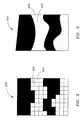
- FIG. 2 is a plan view illustrating a tillable area, wherein the tillable area includes a zone comprising a plurality of grid cells;
- FIG. 3 is a plan view of the tillable area illustrated in FIG. 2, wherein the tillable area includes a zone comprising a polygon; and
- FIG. 4 is a system diagram illustrating a system for providing an input attribute collected in a tillable area while harvesting a crop from the area in accordance with an exemplary embodiment of the present invention.
- Reference will now be made in detail to the presently preferred embodiments of the invention, examples of which are illustrated in the accompanying drawings.
- Referring generally to FIGS. 1 through 4, a
method 100 for providing an input attribute collected in atillable area 200 while harvesting a crop from the tillable area is described in accordance with an exemplary embodiment of the present invention. Preferably, themethod 100 allows an operator to input desired information about thetillable area 200 in the form of the input attribute, such as identifying information collected during the planting and growing phases of the crop production cycle. For example, atstep 102, the input attribute is collected before the crop is harvested. In one specific embodiment, the input attribute describes a type of seed planted, while in other embodiments, the input attribute includes a variety of seed planted, a chemical treatment applied to thetillable area 200, a process performed upon the tillable area, and the like. Those of skill in the art will appreciate that the input attribute may include other descriptive information regarding thetillable area 200 as well, without departing from the scope and intent of the present invention. Further, it will be appreciated that a single input attribute may be utilized to describe a plurality of identifying information. For instance, a first numerical value is utilized to represent a first seed variety planted in combination with a specified fertilizer, while another numerical value is utilized to represent a second seed variety planted in combination with the same fertilizer. - In one specific embodiment, the input attribute is collected by a system 300 from an operator of a
machine 302. Themachine 302 may be a tractor or another machine utilized for applying materials to thetillable area 200. In embodiments, the input attribute is collected from the operator of the machine via auser interface 304. For example, the operator of themachine 302 may specify a seed variety being planted via theuser interface 304, such as inputting the seed variety via a touch screen, a keyboard, or a like input device. Alternatively, the input attribute is collected directly from themachine 302. For example, themachine 302 may specify a chemical treatment being applied to thetillable area 200. In such an instance, aprocessing unit 306 including a data transfer mechanism 308 (e.g. a PC card) may be in communication with themachine 302, for collecting information about the machine's activities in thetillable area 200. For example, themachine 302 may be connected to theprocessing unit 306 and the PC card via acommunication bus 310. Alternatively, themachine 302 may be connected to thedata transfer mechanism 308 via a wireless link. Those of skill in the art will appreciate that the utilization of other techniques for connecting themachine 302 to thedata transfer mechanism 308 would not fall outside the scope and intent of the present invention. It should also be noted that themachine 302 may be connected to anothermachine 312, such as a farming implement for towing behind a tractor. In such an instance, thesecond machine 312 may communicate with themachine 302 viacommunication bus 310, a wireless link, or the like, for providing an input attribute to theprocessing unit 306. Alternatively, thesecond machine 312 may be in direct communication with thedata transfer mechanism 308 via bus architecture, such as thecommunication bus 310, via a wireless link, and the like. - Next, at
step 104, ageographic position 202 occupied by themachine 302 is measured. Preferably, the geographic position of the machine (e.g., latitude and longitude) is measured when the input attribute is collected. In one embodiment, a positioning system is utilized to measure thegeographic position 202 of themachine 302 when the input attribute is collected. For instance, a positioning system receiver assembly receives positioning signals from a positioning system and generates positioning system based navigation information including position (e.g., latitude and longitude), course or heading, speed, time, and the like. In exemplary embodiments, the positioning system receiver assembly receives positioning signals from the Global Positioning System (GPS), a space-based radio-navigation system managed by the United States Air Force for the Government of the United States. However, it is contemplated that the positioning system receiver assembly may alternately be adapted for use with other radio based navigation/global positioning systems such as the GLONASS Navigation Satellite System managed by the Russian Space Agency (RSA) for the Russian Federation. Additionally, in embodiments of the invention, the positioning system receiver assembly may be capable of receiving and utilizing enhanced positioning information provided by differential GPS systems and wide area differential GPS (WADGPS) such as the STARFIRE™ WDGPS system developed by John Deere and Company of Moline, Illinois, the Wide Area Augmentation System (WAAS) provided by the Federal Aviation Administration of the United States Government, or the like. In such embodiments, the positioning system receiver assembly may include, or be coupled to, a radio receiver for receiving differential error correction information. - Preferably, the input attribute and the
geographic position 202 are transmitted from the machine 302 (i.e. from vehicle system 314) to acentral system 316, such as a personal desktop computer, a centrally located server, or the like. In embodiments, the input attribute and thegeographic position 202 are transmitted from theprocessing unit 306 of thevehicle system 314 to thecentral system 316 via a wireless connection, a communication bus, an Internet connection, an intranet connection, or the like, such as an Ethernet connection betweendata transfer mechanism 308 anddata transfer mechanism 318. In one embodiment, the input attribute and thegeographic position 202 are transmitted to the central system after a portion of thetillable area 200 has been traversed by themachine 302, while in a further embodiment, each input attribute andgeographic position 202 is transmitted to thecentral system 316 as it is collected. For example, in one specific embodiment, an operator traverses a portion of thetillable area 200 and then connects hisvehicle system 314 to thecentral system 316 via an Ethernet connection betweendata transfer mechanisms geographic position 202 from theprocessing unit 306 to thecentral system 316. In another embodiment, each input attribute andgeographic position 202 is transmitted via a wireless connection betweendata transfer mechanisms - At
step 106, the input attribute is associated with azone 204 including thegeographic position 202 at which the input attribute was collected while traversing thetillable area 200. In embodiments, thezone 204 includes a plurality of geographic positions within thetillable area 202. Preferably, the plurality of geographic positions included in thezone 204 includes geographic positions for which the same (or sufficiently similar) input attributes have been collected. For instance, each geographic position within thezone 204 is seeded with the same variety of seed. It should be noted that geographic positions within thezone 204 for which sufficiently similar input attributes have been collected may be grouped together utilizing thezone 204, e.g. each geographic position within thezone 204 is seeded with a differing variety of seed for the same crop. Alternatively, where multiple input attributes have been collected, preferably at least one of the multiple input attributes is applicable throughout a zone grouping the input attributes. For example, each geographic position within thezone 204 is seeded with the same variety of seed, but may be fertilized with a differing variety of fertilizer. Thus, in exemplary embodiments, thezone 204 represents a geographic region in which an input attribute associated with thezone 204 is applicable. - At
step 108, thezone 204 is stored along with its associated input attribute. In one embodiment, thezone 204 and the input attribute are stored in the memory of thecentral system 316. In other embodiments, thezone 204 and the input attribute are stored in the memory of thevehicle system 314. It will be appreciated that thezone 204 and the input attribute may be stored in a database, a linked list, or in another data format as contemplated by one of skill in the art. In one specific embodiment, for instance, thezone 204 is stored as one or more grid cells, in which case the input attribute is associated with a grid cell or a plurality of grid cells. In another specific embodiment, thezone 204 is stored as a polygon and the input attribute is associated with the polygon. For example, the polygon may describe a planar surface defined by one exterior boundary and zero or more interior boundaries, each interior boundary describing a portion of the zone not included in the polygon. Those of skill in the art will appreciate that thezone 204 may be stored in various ways without departing from the scope and intent of the present invention. - At
step 110, as the crop planted in thetillable area 200 is harvested, a geographic position occupied by themachine 302 is measured (e.g., latitude and longitude). Those of skill in the art will appreciate that another machine may also be utilized in place ofmachine 302 to harvest a crop, and the location of the other machine would be measured in place ofmachine 302. In embodiments, a positioning system receiver assembly receives positioning signals from a positioning system and generates positioning system based navigation information for the harvesting equipment, including geographic position (e.g., latitude and longitude), course or heading, speed, time, and the like. For example, in one embodiment, a positioning system is utilized to measure the geographic position of themachine 302, while in another embodiment a positioning system is utilized to measure the geographic position of another machine for harvesting the crop planted in thetillable area 200. - At
step 112, the position of the machine measured atstep 110 is compared with thezone 204 stored instep 108. In embodiments, the position of the machine measured atstep 110 is compared with thezone 204 utilizing the processing unit 306 (or another processing unit). If the position of the machine is determined to be within thezone 204, the input attribute associated with thezone 204 is supplied to the operator of the machine via theuser interface 304, atstep 114. For instance, if the position of the machine is within the bounds of a grid cell stored with thezone 204, the input attribute associated with the grid cell is supplied to the operator via theuser interface 304. Alternatively, if the position of the machine measured atstep 110 is within the exterior boundary of a polygon representing the stored zone 204 (but not within an interior boundary), the input attribute associated with thezone 204 is supplied to the operator of the machine via theuser interface 304. More specifically, when a harvesting machine is located atposition 202, the input attribute collected by themachine 302 atlocation 202 is supplied to the operator of the harvesting machine. Further, when the harvesting machine is located within thezone 204 associated with the input attribute collected atlocation 202, the input attribute is supplied to the operator of the harvesting machine. - Those of skill in the art will appreciate that the input attribute, in combination with the zone, may be utilized for segregating a harvested crop. For instance, a crop harvested from the
tillable area 200 may be segregated by harvesting only a portion of the crop located within thezone 204, while harvesting another portion of the crop from another zone having a different input attribute, and keeping the harvested crop loads separated. In this manner, the harvested crop is segregated. This would be desirable for keeping different types of crops separate, e.g. crops fertilized with different materials, and the like. It will also be appreciated that an input attribute collected and associated with a zone may be further associated with a portion of the crop harvested from the zone, such as for identification purposes. For example, a crop harvested inzone 204 is associated with the input attribute collected atgeographic position 202. It is further contemplated that a positioning system, the collected input attribute, and the zone may be utilized for providing automated guidance to a harvesting machine without departing from the scope of the present invention. For instance, an operator may specify a desired portion of the crop for harvesting within thetillable area 200, e.g. a portion of the crop disposed within thezone 204. Then, a harvesting machine may utilize automated guidance functionality in combination with the positioning system for guiding the machine to harvest that portion of the crop disposed within thezone 204. It is contemplated that the utilization of other guidance techniques for segregating a harvested crop utilizing the input attribute and thezone 204 would not fall outside of the scope and spirit of the present invention. - In the exemplary embodiments, the methods disclosed may be implemented as sets of instructions or software readable by a device. Further, it is understood that the specific order or hierarchy of steps in the methods disclosed are examples of exemplary approaches. Based upon design preferences, it is understood that the specific order or hierarchy of steps in the method can be rearranged while remaining within the scope and spirit of the present invention. The accompanying method claims present elements of the various steps in a sample order, and are not necessarily meant to be limited to the specific order or hierarchy presented.
Claims (11)
- A method for providing an input attribute collected in a tillable area (200) while harvesting a crop from the tillable area (200), comprising:collecting the input attribute in the tillable area (200) before the crop is harvested;measuring a first geographic position (202) for the machine (302) when the input attribute is collected;associating the input attribute with a zone (204) including the first geographic position (202), the zone (204) comprised of a plurality of geographic positions in the tillable area (200);storing the zone (204) and the associated input attribute;measuring a second geographic position while harvesting the crop from the tillable area (200);comparing the second geographic position with the zone (204);providing the stored input attribute when the second geographic position is in the zone (204),characterized in that the input attribute is collected from at least one of a machine (302) for applying materials to the tillable area (200) and a user interface (304) that can be operated by an operator of the machine (302).
- The method as claimed in claim 1, wherein the step of collecting the input attribute includes collecting at least one of a type of seed planted, a variety of seed planted, a chemical treatment applied to the tillable area, and a process performed on the tillable area.
- The method as claimed in claim 1, wherein the input attribute is for segregating the harvested crop.
- The method as claimed in claim 1, wherein at least one of the step of measuring the first geographic position (202) and the step of measuring the second geographic position comprises measuring at least one of the first and second geographic positions utilizing a global positioning system (GPS).
- The method as claimed in claim 1, wherein the step of collecting the input attribute comprises collecting the input attribute from a tractor.
- The method as claimed in claim 1, wherein the step of associating the input attribute with the zone (204) comprises associating the input attribute with a grid cell.
- The method as claimed in claim 1, wherein the step of associating the input attribute with the zone (204) comprises associating the input attribute with a polygon.
- The method as claimed in claim 7, wherein the polygon describes a planar surface defined by one exterior boundary and zero or more interior boundaries, each interior boundary describing a portion of the zone not included in the polygon.
- The method as claimed in claim 1, wherein the input attribute is associated with a portion of the crop harvested in the zone.
- A system for providing an input attribute collected in a tillable area while harvesting a crop from the tillable area operable according to the method as claimed in one of claims 1 to 9.
- A system according to claim 10, comprising:a data transfer mechanism (308) for collecting the input attribute in the tillable area (200) before the crop is harvested, the input attribute being collected from at least one of a machine (302) for applying materials to the tillable area and a user interface (304) that can be operated by an operator of the machine (302);a positioning system for measuring a first geographic position for the machine (302) when the input attribute is collected and for measuring a second geographic position while harvesting the crop from the tillable area (200);a memory for storing the input attribute and an associated zone (204) including the first geographic position, the zone (204) comprised of a plurality of geographic positions in the tillable area;a processing unit (306) for comparing the second geographic position with the zone (204); anda user interface (304) for providing the stored input attribute when the second geographic position is in the zone.
Applications Claiming Priority (1)
| Application Number | Priority Date | Filing Date | Title |
|---|---|---|---|
| US11/031,330 US7194965B2 (en) | 2005-01-06 | 2005-01-06 | Variety locator |
Publications (2)
| Publication Number | Publication Date |
|---|---|
| EP1678996A1 true EP1678996A1 (en) | 2006-07-12 |
| EP1678996B1 EP1678996B1 (en) | 2018-09-26 |
Family
ID=35903057
Family Applications (1)
| Application Number | Title | Priority Date | Filing Date |
|---|---|---|---|
| EP05112553.2A Expired - Lifetime EP1678996B1 (en) | 2005-01-06 | 2005-12-21 | Variety locator |
Country Status (6)
| Country | Link |
|---|---|
| US (1) | US7194965B2 (en) |
| EP (1) | EP1678996B1 (en) |
| CN (1) | CN1802891B (en) |
| AU (1) | AU2006200040C1 (en) |
| BR (1) | BRPI0600001A (en) |
| CA (1) | CA2531952C (en) |
Cited By (2)
| Publication number | Priority date | Publication date | Assignee | Title |
|---|---|---|---|---|
| EP1769662A1 (en) * | 2005-09-30 | 2007-04-04 | Claas Saulgau Gmbh | Agricultural working unit with a working device for creating a row of objects |
| WO2007050192A2 (en) | 2005-10-25 | 2007-05-03 | Deere & Company | Crop attribute map input for vehicle guidance |
Families Citing this family (68)
| Publication number | Priority date | Publication date | Assignee | Title |
|---|---|---|---|---|
| WO2011056859A1 (en) * | 2009-11-04 | 2011-05-12 | Wms Gaming, Inc. | Automatic wagering game machine layout mapping |
| US9070249B2 (en) | 2013-01-22 | 2015-06-30 | Wms Gaming, Inc. | Configuring wagering game machines for gaming effects |
| WO2017060168A1 (en) | 2015-10-05 | 2017-04-13 | Bayer Cropscience Ag | Method for operating a harvesting machine with the aid of a plant growth model |
| GB201621879D0 (en) * | 2016-12-21 | 2017-02-01 | Branston Ltd | A crop monitoring system and method |
| US11653588B2 (en) | 2018-10-26 | 2023-05-23 | Deere & Company | Yield map generation and control system |
| US11957072B2 (en) | 2020-02-06 | 2024-04-16 | Deere & Company | Pre-emergence weed detection and mitigation system |
| US11079725B2 (en) | 2019-04-10 | 2021-08-03 | Deere & Company | Machine control using real-time model |
| US11589509B2 (en) | 2018-10-26 | 2023-02-28 | Deere & Company | Predictive machine characteristic map generation and control system |
| US12069978B2 (en) | 2018-10-26 | 2024-08-27 | Deere & Company | Predictive environmental characteristic map generation and control system |
| US11467605B2 (en) | 2019-04-10 | 2022-10-11 | Deere & Company | Zonal machine control |
| US11641800B2 (en) | 2020-02-06 | 2023-05-09 | Deere & Company | Agricultural harvesting machine with pre-emergence weed detection and mitigation system |
| US11240961B2 (en) | 2018-10-26 | 2022-02-08 | Deere & Company | Controlling a harvesting machine based on a geo-spatial representation indicating where the harvesting machine is likely to reach capacity |
| US11672203B2 (en) | 2018-10-26 | 2023-06-13 | Deere & Company | Predictive map generation and control |
| US11178818B2 (en) | 2018-10-26 | 2021-11-23 | Deere & Company | Harvesting machine control system with fill level processing based on yield data |
| CN113226007B (en) * | 2018-12-03 | 2023-04-14 | 迈卡赛斯公司 | Image sensor and thermal imager device and system and method thereof |
| US11234366B2 (en) | 2019-04-10 | 2022-02-01 | Deere & Company | Image selection for machine control |
| US11778945B2 (en) | 2019-04-10 | 2023-10-10 | Deere & Company | Machine control using real-time model |
| US12225846B2 (en) | 2020-02-06 | 2025-02-18 | Deere & Company | Machine control using a predictive map |
| US12329148B2 (en) | 2020-02-06 | 2025-06-17 | Deere & Company | Predictive weed map and material application machine control |
| US12035648B2 (en) | 2020-02-06 | 2024-07-16 | Deere & Company | Predictive weed map generation and control system |
| US11477940B2 (en) | 2020-03-26 | 2022-10-25 | Deere & Company | Mobile work machine control based on zone parameter modification |
| US11927459B2 (en) | 2020-10-09 | 2024-03-12 | Deere & Company | Machine control using a predictive map |
| US11983009B2 (en) | 2020-10-09 | 2024-05-14 | Deere & Company | Map generation and control system |
| US20220110238A1 (en) | 2020-10-09 | 2022-04-14 | Deere & Company | Machine control using a predictive map |
| US11635765B2 (en) | 2020-10-09 | 2023-04-25 | Deere & Company | Crop state map generation and control system |
| US11864483B2 (en) | 2020-10-09 | 2024-01-09 | Deere & Company | Predictive map generation and control system |
| US12419220B2 (en) | 2020-10-09 | 2025-09-23 | Deere & Company | Predictive map generation and control system |
| US11849671B2 (en) | 2020-10-09 | 2023-12-26 | Deere & Company | Crop state map generation and control system |
| US12550802B2 (en) | 2020-10-08 | 2026-02-17 | Deere & Company | Predictive machine characteristic map generation and control system |
| US11711995B2 (en) | 2020-10-09 | 2023-08-01 | Deere & Company | Machine control using a predictive map |
| US11844311B2 (en) | 2020-10-09 | 2023-12-19 | Deere & Company | Machine control using a predictive map |
| US11474523B2 (en) | 2020-10-09 | 2022-10-18 | Deere & Company | Machine control using a predictive speed map |
| US12178158B2 (en) | 2020-10-09 | 2024-12-31 | Deere & Company | Predictive map generation and control system for an agricultural work machine |
| US11849672B2 (en) | 2020-10-09 | 2023-12-26 | Deere & Company | Machine control using a predictive map |
| US20220110258A1 (en) | 2020-10-09 | 2022-04-14 | Deere & Company | Map generation and control system |
| US11675354B2 (en) | 2020-10-09 | 2023-06-13 | Deere & Company | Machine control using a predictive map |
| US12013245B2 (en) | 2020-10-09 | 2024-06-18 | Deere & Company | Predictive map generation and control system |
| US11874669B2 (en) | 2020-10-09 | 2024-01-16 | Deere & Company | Map generation and control system |
| US11845449B2 (en) | 2020-10-09 | 2023-12-19 | Deere & Company | Map generation and control system |
| US11650587B2 (en) | 2020-10-09 | 2023-05-16 | Deere & Company | Predictive power map generation and control system |
| US11871697B2 (en) | 2020-10-09 | 2024-01-16 | Deere & Company | Crop moisture map generation and control system |
| US11895948B2 (en) | 2020-10-09 | 2024-02-13 | Deere & Company | Predictive map generation and control based on soil properties |
| US12069986B2 (en) | 2020-10-09 | 2024-08-27 | Deere & Company | Map generation and control system |
| US11825768B2 (en) | 2020-10-09 | 2023-11-28 | Deere & Company | Machine control using a predictive map |
| US12386354B2 (en) | 2020-10-09 | 2025-08-12 | Deere & Company | Predictive power map generation and control system |
| US11727680B2 (en) | 2020-10-09 | 2023-08-15 | Deere & Company | Predictive map generation based on seeding characteristics and control |
| US12422847B2 (en) | 2020-10-09 | 2025-09-23 | Deere & Company | Predictive agricultural model and map generation |
| US11592822B2 (en) | 2020-10-09 | 2023-02-28 | Deere & Company | Machine control using a predictive map |
| US11889788B2 (en) | 2020-10-09 | 2024-02-06 | Deere & Company | Predictive biomass map generation and control |
| US11946747B2 (en) | 2020-10-09 | 2024-04-02 | Deere & Company | Crop constituent map generation and control system |
| US12250905B2 (en) | 2020-10-09 | 2025-03-18 | Deere & Company | Machine control using a predictive map |
| US11889787B2 (en) | 2020-10-09 | 2024-02-06 | Deere & Company | Predictive speed map generation and control system |
| US12127500B2 (en) | 2021-01-27 | 2024-10-29 | Deere & Company | Machine control using a map with regime zones |
| US12364193B2 (en) * | 2021-06-08 | 2025-07-22 | Deere & Company | Row sense operations with context sensing |
| US12229886B2 (en) | 2021-10-01 | 2025-02-18 | Deere & Company | Historical crop state model, predictive crop state map generation and control system |
| US11803863B2 (en) | 2021-12-13 | 2023-10-31 | Crop Search Llc | System and method for food safety audit and sampling |
| US12310286B2 (en) | 2021-12-14 | 2025-05-27 | Deere & Company | Crop constituent sensing |
| US12302791B2 (en) | 2021-12-20 | 2025-05-20 | Deere & Company | Crop constituents, predictive mapping, and agricultural harvester control |
| US12245549B2 (en) | 2022-01-11 | 2025-03-11 | Deere & Company | Predictive response map generation and control system |
| US12520759B2 (en) | 2022-01-26 | 2026-01-13 | Deere & Company | Systems and methods for predicting material dynamics |
| US12082531B2 (en) | 2022-01-26 | 2024-09-10 | Deere & Company | Systems and methods for predicting material dynamics |
| US12295288B2 (en) | 2022-04-05 | 2025-05-13 | Deere &Company | Predictive machine setting map generation and control system |
| US12284934B2 (en) | 2022-04-08 | 2025-04-29 | Deere & Company | Systems and methods for predictive tractive characteristics and control |
| US12358493B2 (en) | 2022-04-08 | 2025-07-15 | Deere & Company | Systems and methods for predictive power requirements and control |
| US12582035B2 (en) | 2022-04-08 | 2026-03-24 | Deere & Company | Systems and methods for predictive power requirements and control |
| US12058951B2 (en) | 2022-04-08 | 2024-08-13 | Deere & Company | Predictive nutrient map and control |
| US12298767B2 (en) | 2022-04-08 | 2025-05-13 | Deere & Company | Predictive material consumption map and control |
| US12556630B2 (en) | 2022-10-31 | 2026-02-17 | Crop Search Llc | System and method for food safety audit and sampling |
Citations (6)
| Publication number | Priority date | Publication date | Assignee | Title |
|---|---|---|---|---|
| GB2178934A (en) * | 1985-03-22 | 1987-02-25 | Massey Ferguson Mfg | Agricultural husbandry |
| EP0723740A1 (en) | 1995-01-25 | 1996-07-31 | Massey Ferguson Manufacturing Limited | Crop harvester |
| US5771169A (en) * | 1996-08-29 | 1998-06-23 | Case Corporation | Site-specific harvest statistics analyzer |
| US5870689A (en) * | 1996-11-22 | 1999-02-09 | Case Corporation | Scouting system for an agricultural field |
| US20020035431A1 (en) * | 2000-06-05 | 2002-03-21 | Todd Ell | System and method for creating application maps for site-specific farming |
| US20030159633A1 (en) * | 2001-06-29 | 2003-08-28 | The Regents Of The University Of California | Method and apparatus for ultra precise GPS-based mapping of seeds or vegetation during planting |
Family Cites Families (2)
| Publication number | Priority date | Publication date | Assignee | Title |
|---|---|---|---|---|
| US6789014B1 (en) * | 2003-05-09 | 2004-09-07 | Deere & Company | Direct modification of DGPS information with inertial measurement data |
| CN2666122Y (en) * | 2003-12-19 | 2004-12-29 | 潘美楷 | Combine harvester working condition monitor |
-
2005
- 2005-01-06 US US11/031,330 patent/US7194965B2/en not_active Expired - Lifetime
- 2005-12-13 CN CN200510134620.5A patent/CN1802891B/en not_active Expired - Fee Related
- 2005-12-21 EP EP05112553.2A patent/EP1678996B1/en not_active Expired - Lifetime
-
2006
- 2006-01-02 BR BRPI0600001-0A patent/BRPI0600001A/en not_active Application Discontinuation
- 2006-01-04 CA CA002531952A patent/CA2531952C/en not_active Expired - Fee Related
- 2006-01-06 AU AU2006200040A patent/AU2006200040C1/en not_active Ceased
Patent Citations (6)
| Publication number | Priority date | Publication date | Assignee | Title |
|---|---|---|---|---|
| GB2178934A (en) * | 1985-03-22 | 1987-02-25 | Massey Ferguson Mfg | Agricultural husbandry |
| EP0723740A1 (en) | 1995-01-25 | 1996-07-31 | Massey Ferguson Manufacturing Limited | Crop harvester |
| US5771169A (en) * | 1996-08-29 | 1998-06-23 | Case Corporation | Site-specific harvest statistics analyzer |
| US5870689A (en) * | 1996-11-22 | 1999-02-09 | Case Corporation | Scouting system for an agricultural field |
| US20020035431A1 (en) * | 2000-06-05 | 2002-03-21 | Todd Ell | System and method for creating application maps for site-specific farming |
| US20030159633A1 (en) * | 2001-06-29 | 2003-08-28 | The Regents Of The University Of California | Method and apparatus for ultra precise GPS-based mapping of seeds or vegetation during planting |
Cited By (3)
| Publication number | Priority date | Publication date | Assignee | Title |
|---|---|---|---|---|
| EP1769662A1 (en) * | 2005-09-30 | 2007-04-04 | Claas Saulgau Gmbh | Agricultural working unit with a working device for creating a row of objects |
| WO2007050192A2 (en) | 2005-10-25 | 2007-05-03 | Deere & Company | Crop attribute map input for vehicle guidance |
| EP1943877A4 (en) * | 2005-10-25 | 2012-03-28 | Deere & Co | Crop attribute map input for vehicle guidance |
Also Published As
| Publication number | Publication date |
|---|---|
| CA2531952C (en) | 2009-03-31 |
| CA2531952A1 (en) | 2006-07-06 |
| BRPI0600001A (en) | 2007-07-17 |
| AU2006200040A1 (en) | 2006-07-20 |
| CN1802891B (en) | 2014-07-02 |
| EP1678996B1 (en) | 2018-09-26 |
| US7194965B2 (en) | 2007-03-27 |
| AU2006200040B2 (en) | 2011-12-01 |
| AU2006200040C1 (en) | 2012-06-21 |
| US20060162631A1 (en) | 2006-07-27 |
| CN1802891A (en) | 2006-07-19 |
Similar Documents
| Publication | Publication Date | Title |
|---|---|---|
| US7194965B2 (en) | Variety locator | |
| US5878371A (en) | Method and apparatus for synthesizing site-specific farming data | |
| US8417534B2 (en) | Automated location-based information recall | |
| US20200334766A1 (en) | Agricultural field management system | |
| EP3598319B1 (en) | Methods for generating soil maps and application prescriptions | |
| US9715231B2 (en) | Agriculture support system | |
| US20220174935A1 (en) | Method for remediating developmentally delayed plants | |
| JP7478066B2 (en) | Work management system, work management method, and work management program | |
| WO1998021929A1 (en) | Scouting system for an agricultural field | |
| WO2011139590A2 (en) | System, method, and computer program product for managing a research seed location | |
| EP3193303A1 (en) | Information processing device, information processing method, and program | |
| EP3193302A1 (en) | Information processing device, information processing method, and program | |
| JP2020004438A (en) | Farm field management system | |
| JP6938356B2 (en) | Agricultural support system and agricultural support equipment | |
| Shamshiri et al. | Exploring GPS data for operational analysis of farm machinery | |
| WO2022097552A1 (en) | Work information management device, storage medium, and work information management method | |
| Thomasson et al. | Mississippi cotton yield monitor: Three years of field-test results | |
| JP6163056B2 (en) | Agricultural support system | |
| CN116113315A (en) | Job management system, job management method, and job management program | |
| JP2018165989A (en) | Firm field management system | |
| JP7510305B2 (en) | Work management system, work management method, and work management program | |
| JP2022036523A (en) | Work management system, work management method, and work management program | |
| Griffin et al. | Precision Agriculture Technology Adoption and Obsolescence | |
| EP4643625A1 (en) | Field registration device, field registration method, and computer program | |
| EP3949711B1 (en) | Work map provision server |
Legal Events
| Date | Code | Title | Description |
|---|---|---|---|
| PUAI | Public reference made under article 153(3) epc to a published international application that has entered the european phase |
Free format text: ORIGINAL CODE: 0009012 |
|
| AK | Designated contracting states |
Kind code of ref document: A1 Designated state(s): AT BE BG CH CY CZ DE DK EE ES FI FR GB GR HU IE IS IT LI LT LU LV MC NL PL PT RO SE SI SK TR |
|
| AX | Request for extension of the european patent |
Extension state: AL BA HR MK YU |
|
| 17P | Request for examination filed |
Effective date: 20070112 |
|
| AKX | Designation fees paid |
Designated state(s): AT BE BG CH CY CZ DE DK EE ES FI FR GB GR HU IE IS IT LI LT LU LV MC NL PL PT RO SE SI SK TR |
|
| 17Q | First examination report despatched |
Effective date: 20070222 |
|
| GRAP | Despatch of communication of intention to grant a patent |
Free format text: ORIGINAL CODE: EPIDOSNIGR1 |
|
| INTG | Intention to grant announced |
Effective date: 20180419 |
|
| RIN1 | Information on inventor provided before grant (corrected) |
Inventor name: BAJC, MICHAEL Inventor name: SUTTON, CRAIG A. Inventor name: HICKEY, DAVID W. |
|
| GRAS | Grant fee paid |
Free format text: ORIGINAL CODE: EPIDOSNIGR3 |
|
| GRAA | (expected) grant |
Free format text: ORIGINAL CODE: 0009210 |
|
| AK | Designated contracting states |
Kind code of ref document: B1 Designated state(s): AT BE BG CH CY CZ DE DK EE ES FI FR GB GR HU IE IS IT LI LT LU LV MC NL PL PT RO SE SI SK TR |
|
| REG | Reference to a national code |
Ref country code: GB Ref legal event code: FG4D |
|
| REG | Reference to a national code |
Ref country code: CH Ref legal event code: EP |
|
| REG | Reference to a national code |
Ref country code: AT Ref legal event code: REF Ref document number: 1044899 Country of ref document: AT Kind code of ref document: T Effective date: 20181015 |
|
| REG | Reference to a national code |
Ref country code: IE Ref legal event code: FG4D |
|
| REG | Reference to a national code |
Ref country code: DE Ref legal event code: R096 Ref document number: 602005054663 Country of ref document: DE |
|
| REG | Reference to a national code |
Ref country code: NL Ref legal event code: MP Effective date: 20180926 |
|
| PG25 | Lapsed in a contracting state [announced via postgrant information from national office to epo] |
Ref country code: LT Free format text: LAPSE BECAUSE OF FAILURE TO SUBMIT A TRANSLATION OF THE DESCRIPTION OR TO PAY THE FEE WITHIN THE PRESCRIBED TIME-LIMIT Effective date: 20180926 Ref country code: BG Free format text: LAPSE BECAUSE OF FAILURE TO SUBMIT A TRANSLATION OF THE DESCRIPTION OR TO PAY THE FEE WITHIN THE PRESCRIBED TIME-LIMIT Effective date: 20181226 Ref country code: SE Free format text: LAPSE BECAUSE OF FAILURE TO SUBMIT A TRANSLATION OF THE DESCRIPTION OR TO PAY THE FEE WITHIN THE PRESCRIBED TIME-LIMIT Effective date: 20180926 Ref country code: GR Free format text: LAPSE BECAUSE OF FAILURE TO SUBMIT A TRANSLATION OF THE DESCRIPTION OR TO PAY THE FEE WITHIN THE PRESCRIBED TIME-LIMIT Effective date: 20181227 Ref country code: FI Free format text: LAPSE BECAUSE OF FAILURE TO SUBMIT A TRANSLATION OF THE DESCRIPTION OR TO PAY THE FEE WITHIN THE PRESCRIBED TIME-LIMIT Effective date: 20180926 |
|
| REG | Reference to a national code |
Ref country code: LT Ref legal event code: MG4D |
|
| PG25 | Lapsed in a contracting state [announced via postgrant information from national office to epo] |
Ref country code: LV Free format text: LAPSE BECAUSE OF FAILURE TO SUBMIT A TRANSLATION OF THE DESCRIPTION OR TO PAY THE FEE WITHIN THE PRESCRIBED TIME-LIMIT Effective date: 20180926 |
|
| REG | Reference to a national code |
Ref country code: AT Ref legal event code: MK05 Ref document number: 1044899 Country of ref document: AT Kind code of ref document: T Effective date: 20180926 |
|
| PG25 | Lapsed in a contracting state [announced via postgrant information from national office to epo] |
Ref country code: ES Free format text: LAPSE BECAUSE OF FAILURE TO SUBMIT A TRANSLATION OF THE DESCRIPTION OR TO PAY THE FEE WITHIN THE PRESCRIBED TIME-LIMIT Effective date: 20180926 Ref country code: IS Free format text: LAPSE BECAUSE OF FAILURE TO SUBMIT A TRANSLATION OF THE DESCRIPTION OR TO PAY THE FEE WITHIN THE PRESCRIBED TIME-LIMIT Effective date: 20190126 Ref country code: AT Free format text: LAPSE BECAUSE OF FAILURE TO SUBMIT A TRANSLATION OF THE DESCRIPTION OR TO PAY THE FEE WITHIN THE PRESCRIBED TIME-LIMIT Effective date: 20180926 Ref country code: IT Free format text: LAPSE BECAUSE OF FAILURE TO SUBMIT A TRANSLATION OF THE DESCRIPTION OR TO PAY THE FEE WITHIN THE PRESCRIBED TIME-LIMIT Effective date: 20180926 Ref country code: PL Free format text: LAPSE BECAUSE OF FAILURE TO SUBMIT A TRANSLATION OF THE DESCRIPTION OR TO PAY THE FEE WITHIN THE PRESCRIBED TIME-LIMIT Effective date: 20180926 Ref country code: EE Free format text: LAPSE BECAUSE OF FAILURE TO SUBMIT A TRANSLATION OF THE DESCRIPTION OR TO PAY THE FEE WITHIN THE PRESCRIBED TIME-LIMIT Effective date: 20180926 Ref country code: CZ Free format text: LAPSE BECAUSE OF FAILURE TO SUBMIT A TRANSLATION OF THE DESCRIPTION OR TO PAY THE FEE WITHIN THE PRESCRIBED TIME-LIMIT Effective date: 20180926 Ref country code: RO Free format text: LAPSE BECAUSE OF FAILURE TO SUBMIT A TRANSLATION OF THE DESCRIPTION OR TO PAY THE FEE WITHIN THE PRESCRIBED TIME-LIMIT Effective date: 20180926 Ref country code: NL Free format text: LAPSE BECAUSE OF FAILURE TO SUBMIT A TRANSLATION OF THE DESCRIPTION OR TO PAY THE FEE WITHIN THE PRESCRIBED TIME-LIMIT Effective date: 20180926 |
|
| PG25 | Lapsed in a contracting state [announced via postgrant information from national office to epo] |
Ref country code: PT Free format text: LAPSE BECAUSE OF FAILURE TO SUBMIT A TRANSLATION OF THE DESCRIPTION OR TO PAY THE FEE WITHIN THE PRESCRIBED TIME-LIMIT Effective date: 20190126 Ref country code: SK Free format text: LAPSE BECAUSE OF FAILURE TO SUBMIT A TRANSLATION OF THE DESCRIPTION OR TO PAY THE FEE WITHIN THE PRESCRIBED TIME-LIMIT Effective date: 20180926 |
|
| REG | Reference to a national code |
Ref country code: DE Ref legal event code: R097 Ref document number: 602005054663 Country of ref document: DE |
|
| PG25 | Lapsed in a contracting state [announced via postgrant information from national office to epo] |
Ref country code: DK Free format text: LAPSE BECAUSE OF FAILURE TO SUBMIT A TRANSLATION OF THE DESCRIPTION OR TO PAY THE FEE WITHIN THE PRESCRIBED TIME-LIMIT Effective date: 20180926 |
|
| REG | Reference to a national code |
Ref country code: CH Ref legal event code: PL |
|
| PLBE | No opposition filed within time limit |
Free format text: ORIGINAL CODE: 0009261 |
|
| STAA | Information on the status of an ep patent application or granted ep patent |
Free format text: STATUS: NO OPPOSITION FILED WITHIN TIME LIMIT |
|
| PG25 | Lapsed in a contracting state [announced via postgrant information from national office to epo] |
Ref country code: LU Free format text: LAPSE BECAUSE OF NON-PAYMENT OF DUE FEES Effective date: 20181221 Ref country code: MC Free format text: LAPSE BECAUSE OF FAILURE TO SUBMIT A TRANSLATION OF THE DESCRIPTION OR TO PAY THE FEE WITHIN THE PRESCRIBED TIME-LIMIT Effective date: 20180926 |
|
| 26N | No opposition filed |
Effective date: 20190627 |
|
| REG | Reference to a national code |
Ref country code: IE Ref legal event code: MM4A |
|
| REG | Reference to a national code |
Ref country code: BE Ref legal event code: MM Effective date: 20181231 |
|
| PG25 | Lapsed in a contracting state [announced via postgrant information from national office to epo] |
Ref country code: FR Free format text: LAPSE BECAUSE OF NON-PAYMENT OF DUE FEES Effective date: 20181231 Ref country code: SI Free format text: LAPSE BECAUSE OF FAILURE TO SUBMIT A TRANSLATION OF THE DESCRIPTION OR TO PAY THE FEE WITHIN THE PRESCRIBED TIME-LIMIT Effective date: 20180926 Ref country code: IE Free format text: LAPSE BECAUSE OF NON-PAYMENT OF DUE FEES Effective date: 20181221 |
|
| PG25 | Lapsed in a contracting state [announced via postgrant information from national office to epo] |
Ref country code: BE Free format text: LAPSE BECAUSE OF NON-PAYMENT OF DUE FEES Effective date: 20181231 |
|
| PG25 | Lapsed in a contracting state [announced via postgrant information from national office to epo] |
Ref country code: LI Free format text: LAPSE BECAUSE OF NON-PAYMENT OF DUE FEES Effective date: 20181231 Ref country code: CH Free format text: LAPSE BECAUSE OF NON-PAYMENT OF DUE FEES Effective date: 20181231 |
|
| PG25 | Lapsed in a contracting state [announced via postgrant information from national office to epo] |
Ref country code: TR Free format text: LAPSE BECAUSE OF FAILURE TO SUBMIT A TRANSLATION OF THE DESCRIPTION OR TO PAY THE FEE WITHIN THE PRESCRIBED TIME-LIMIT Effective date: 20180926 |
|
| PG25 | Lapsed in a contracting state [announced via postgrant information from national office to epo] |
Ref country code: CY Free format text: LAPSE BECAUSE OF FAILURE TO SUBMIT A TRANSLATION OF THE DESCRIPTION OR TO PAY THE FEE WITHIN THE PRESCRIBED TIME-LIMIT Effective date: 20180926 Ref country code: HU Free format text: LAPSE BECAUSE OF FAILURE TO SUBMIT A TRANSLATION OF THE DESCRIPTION OR TO PAY THE FEE WITHIN THE PRESCRIBED TIME-LIMIT; INVALID AB INITIO Effective date: 20051221 |
|
| PGFP | Annual fee paid to national office [announced via postgrant information from national office to epo] |
Ref country code: GB Payment date: 20231227 Year of fee payment: 19 |
|
| PGFP | Annual fee paid to national office [announced via postgrant information from national office to epo] |
Ref country code: DE Payment date: 20231121 Year of fee payment: 19 |
|
| REG | Reference to a national code |
Ref country code: DE Ref legal event code: R119 Ref document number: 602005054663 Country of ref document: DE |
|
| GBPC | Gb: european patent ceased through non-payment of renewal fee |
Effective date: 20241221 |
|
| PG25 | Lapsed in a contracting state [announced via postgrant information from national office to epo] |
Ref country code: DE Free format text: LAPSE BECAUSE OF NON-PAYMENT OF DUE FEES Effective date: 20250701 |
|
| PG25 | Lapsed in a contracting state [announced via postgrant information from national office to epo] |
Ref country code: GB Free format text: LAPSE BECAUSE OF NON-PAYMENT OF DUE FEES Effective date: 20241221 |