EP1678730B1 - Gas remover apparatus and method - Google Patents
Gas remover apparatus and method Download PDFInfo
- Publication number
- EP1678730B1 EP1678730B1 EP04795742A EP04795742A EP1678730B1 EP 1678730 B1 EP1678730 B1 EP 1678730B1 EP 04795742 A EP04795742 A EP 04795742A EP 04795742 A EP04795742 A EP 04795742A EP 1678730 B1 EP1678730 B1 EP 1678730B1
- Authority
- EP
- European Patent Office
- Prior art keywords
- gas
- gas remover
- nitrogen
- load tap
- tap changer
- Prior art date
- Legal status (The legal status is an assumption and is not a legal conclusion. Google has not performed a legal analysis and makes no representation as to the accuracy of the status listed.)
- Expired - Lifetime
Links
- 238000000034 method Methods 0.000 title description 5
- IJGRMHOSHXDMSA-UHFFFAOYSA-N Atomic nitrogen Chemical compound N#N IJGRMHOSHXDMSA-UHFFFAOYSA-N 0.000 claims abstract description 168
- 229910052757 nitrogen Inorganic materials 0.000 claims abstract description 82
- 239000007789 gas Substances 0.000 claims abstract description 71
- 239000000356 contaminant Substances 0.000 claims abstract description 14
- XLYOFNOQVPJJNP-UHFFFAOYSA-N water Substances O XLYOFNOQVPJJNP-UHFFFAOYSA-N 0.000 claims abstract description 12
- 238000013022 venting Methods 0.000 claims abstract description 7
- QVGXLLKOCUKJST-UHFFFAOYSA-N atomic oxygen Chemical compound [O] QVGXLLKOCUKJST-UHFFFAOYSA-N 0.000 claims abstract description 5
- 239000001301 oxygen Substances 0.000 claims abstract description 5
- 229910052760 oxygen Inorganic materials 0.000 claims abstract description 5
- 230000033228 biological regulation Effects 0.000 claims description 7
- 239000012528 membrane Substances 0.000 claims description 6
- 239000002480 mineral oil Substances 0.000 claims description 5
- 235000010446 mineral oil Nutrition 0.000 claims description 5
- 238000003860 storage Methods 0.000 claims description 5
- 239000011521 glass Substances 0.000 claims description 3
- 239000001307 helium Substances 0.000 claims description 3
- 229910052734 helium Inorganic materials 0.000 claims description 3
- SWQJXJOGLNCZEY-UHFFFAOYSA-N helium atom Chemical compound [He] SWQJXJOGLNCZEY-UHFFFAOYSA-N 0.000 claims description 3
- 230000007246 mechanism Effects 0.000 claims description 3
- 239000012808 vapor phase Substances 0.000 claims description 3
- 229910052756 noble gas Inorganic materials 0.000 claims description 2
- 230000001105 regulatory effect Effects 0.000 claims description 2
- RAHZWNYVWXNFOC-UHFFFAOYSA-N Sulphur dioxide Chemical compound O=S=O RAHZWNYVWXNFOC-UHFFFAOYSA-N 0.000 claims 2
- RWSOTUBLDIXVET-UHFFFAOYSA-N Dihydrogen sulfide Chemical compound S RWSOTUBLDIXVET-UHFFFAOYSA-N 0.000 claims 1
- CBENFWSGALASAD-UHFFFAOYSA-N Ozone Chemical compound [O-][O+]=O CBENFWSGALASAD-UHFFFAOYSA-N 0.000 claims 1
- 150000001722 carbon compounds Chemical class 0.000 claims 1
- 230000001419 dependent effect Effects 0.000 claims 1
- 238000001914 filtration Methods 0.000 claims 1
- 229910000037 hydrogen sulfide Inorganic materials 0.000 claims 1
- 239000000463 material Substances 0.000 claims 1
- 230000015556 catabolic process Effects 0.000 abstract description 5
- 230000001066 destructive effect Effects 0.000 abstract description 3
- 239000002360 explosive Substances 0.000 abstract description 3
- 231100001261 hazardous Toxicity 0.000 abstract 1
- 239000003921 oil Substances 0.000 description 23
- 239000007788 liquid Substances 0.000 description 5
- 230000008859 change Effects 0.000 description 4
- 229910001873 dinitrogen Inorganic materials 0.000 description 4
- 230000006870 function Effects 0.000 description 4
- 238000012423 maintenance Methods 0.000 description 4
- 239000002245 particle Substances 0.000 description 4
- 238000004804 winding Methods 0.000 description 4
- 230000008901 benefit Effects 0.000 description 3
- 238000010276 construction Methods 0.000 description 3
- 238000009826 distribution Methods 0.000 description 3
- 238000013035 low temperature curing Methods 0.000 description 3
- 239000007800 oxidant agent Substances 0.000 description 3
- 150000001875 compounds Chemical class 0.000 description 2
- -1 corrosive Substances 0.000 description 2
- 238000006731 degradation reaction Methods 0.000 description 2
- 238000010586 diagram Methods 0.000 description 2
- 230000000694 effects Effects 0.000 description 2
- 239000012530 fluid Substances 0.000 description 2
- 238000012986 modification Methods 0.000 description 2
- 230000004048 modification Effects 0.000 description 2
- 239000003209 petroleum derivative Substances 0.000 description 2
- 238000010926 purge Methods 0.000 description 2
- 230000009467 reduction Effects 0.000 description 2
- 230000004044 response Effects 0.000 description 2
- 239000004215 Carbon black (E152) Substances 0.000 description 1
- 238000005299 abrasion Methods 0.000 description 1
- 238000010521 absorption reaction Methods 0.000 description 1
- 230000005540 biological transmission Effects 0.000 description 1
- 230000015572 biosynthetic process Effects 0.000 description 1
- 239000006227 byproduct Substances 0.000 description 1
- 239000003795 chemical substances by application Substances 0.000 description 1
- 230000003749 cleanliness Effects 0.000 description 1
- 238000004891 communication Methods 0.000 description 1
- 238000011109 contamination Methods 0.000 description 1
- 238000001816 cooling Methods 0.000 description 1
- 238000005260 corrosion Methods 0.000 description 1
- 230000007797 corrosion Effects 0.000 description 1
- 239000002274 desiccant Substances 0.000 description 1
- 238000011161 development Methods 0.000 description 1
- 238000009792 diffusion process Methods 0.000 description 1
- 238000006073 displacement reaction Methods 0.000 description 1
- 238000005516 engineering process Methods 0.000 description 1
- 230000002708 enhancing effect Effects 0.000 description 1
- 238000007667 floating Methods 0.000 description 1
- 239000006260 foam Substances 0.000 description 1
- 230000005484 gravity Effects 0.000 description 1
- 238000010438 heat treatment Methods 0.000 description 1
- 229930195733 hydrocarbon Natural products 0.000 description 1
- 150000002430 hydrocarbons Chemical class 0.000 description 1
- 230000004941 influx Effects 0.000 description 1
- 238000009434 installation Methods 0.000 description 1
- 238000009413 insulation Methods 0.000 description 1
- 238000004519 manufacturing process Methods 0.000 description 1
- 239000000203 mixture Substances 0.000 description 1
- 150000002835 noble gases Chemical class 0.000 description 1
- 150000007524 organic acids Chemical class 0.000 description 1
- 235000005985 organic acids Nutrition 0.000 description 1
- 230000000737 periodic effect Effects 0.000 description 1
- 239000003208 petroleum Substances 0.000 description 1
- 239000012071 phase Substances 0.000 description 1
- 230000002028 premature Effects 0.000 description 1
- 239000000047 product Substances 0.000 description 1
- 230000009257 reactivity Effects 0.000 description 1
- 238000006722 reduction reaction Methods 0.000 description 1
- 230000008439 repair process Effects 0.000 description 1
- 230000001629 suppression Effects 0.000 description 1
- 239000000725 suspension Substances 0.000 description 1
- 239000002918 waste heat Substances 0.000 description 1
Images

Classifications
-
- H—ELECTRICITY
- H01—ELECTRIC ELEMENTS
- H01H—ELECTRIC SWITCHES; RELAYS; SELECTORS; EMERGENCY PROTECTIVE DEVICES
- H01H9/00—Details of switching devices, not covered by groups H01H1/00 - H01H7/00
-
- H—ELECTRICITY
- H01—ELECTRIC ELEMENTS
- H01F—MAGNETS; INDUCTANCES; TRANSFORMERS; SELECTION OF MATERIALS FOR THEIR MAGNETIC PROPERTIES
- H01F27/00—Details of transformers or inductances, in general
- H01F27/08—Cooling; Ventilating
- H01F27/10—Liquid cooling
- H01F27/12—Oil cooling
- H01F27/14—Expansion chambers; Oil conservators; Gas cushions; Arrangements for purifying, drying, or filling
-
- H—ELECTRICITY
- H01—ELECTRIC ELEMENTS
- H01F—MAGNETS; INDUCTANCES; TRANSFORMERS; SELECTION OF MATERIALS FOR THEIR MAGNETIC PROPERTIES
- H01F27/00—Details of transformers or inductances, in general
-
- H—ELECTRICITY
- H01—ELECTRIC ELEMENTS
- H01H—ELECTRIC SWITCHES; RELAYS; SELECTORS; EMERGENCY PROTECTIVE DEVICES
- H01H9/00—Details of switching devices, not covered by groups H01H1/00 - H01H7/00
- H01H9/0005—Tap change devices
- H01H9/0044—Casings; Mountings; Disposition in transformer housing
Definitions
- the present invention relates generally to oil-filled switching apparatus for electrical substations and other high-voltage, high-power applications. More particularly, the invention relates to apparatus for maintaining an environment free of excessive pressure and explosive vapors in head space above the oil that fills load tap changers.
- LTC load tap changer
- oil may refer to one of a variety of petroleum distillates which are in the liquid state at room temperature, for insulation, cooling, and reduction of arcing.
- Numerous petroleum distillates may be suited to particular applications, as determined by operating temperature range, viscosity requirements, water absorption, electrical properties such as dielectric coefficient, conductivity, and change in electrical properties with moisture concentration, temperature, and the like.
- the non-oil-filled gas volume at the top of the open chamber in a tap changer, transformer, or other device is termed ullage.
- the pressure in the ullage in an LTC tends to change slowly with outside temperature, as the oil volume typically can provide a significant thermal reservoir.
- the immersed tap switching events can produce arcing, which tends to break down the oil, leaving contaminating particles as well as liquid and gas hydrocarbon molecules of various molecular weights.
- a portion of the contaminating particles can be deposited on the sliding contacts of the LTC, building up a resistive layer and increasing contact heating, with the waste heat ultimately coupled to the oil. Removal of these deposits is promoted by abrasion between the sliding contacts during each tap change.
- Another portion of the contaminating particles can remain in suspension in the oil until mechanically removed by passing the oil through a filter.
- Still another portion of the contaminating particles may sink to the bottom of the oil volume, while others float to the surface or form foams.
- An LTC can be vented rather than being hermetically sealed, so that there is some opportunity in many systems for water vapor and other airborne contaminants to enter the system; the contaminants can be absorbed by the oil, can be entrained as corrosion promoters, and can be shown to directly lower the dielectric constant of the oil.
- a variety of known technologies can serve for suppression of entrainment of water vapor, such as the use of a desiccant within the ullage of the LTC.
- a gas remover system that controls an environment in a load tap changer (LTC), comprising a nitrogen generator to extract nitrogen from the atmosphere; a feed line to introduce the nitrogen extracted by the nitrogen generator into an ullage in the LTC; an orifice to establish a substantially continuos outflow rate of nitrogen to expel entrained vapor phase contaminantsfrom the LTC ullage to the atmosphere; and at least one sight glass on the LTC to permit examination of the inside of the LTC, wherein the LTC contains mineral oil.
- LTC load tap changer
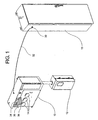
- FIG. 1 is a perspective view of a load tap changer configured to include the inventive apparatus.
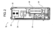
- FIG. 2 is a front view without the door of a nitrogen gas generator of the type used to maintain nitrogen gas charge in a transformer and its associated load tap changer and other apparatus.
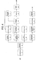
- FIG. 4 is a system block diagram showing a transformer, to which are affixed a load tap changer and a nitrogen gas generator.
- a nitrogen gas based contaminant gas remover apparatus and method which allows displacement of gases through a generally continuous bleed of nitrogen introduced from a nitrogen source and released using a vent orifice.
- the expelled gases may include contaminant, corrosive, explosive, and/or pressurizing gases, for example.
- FIG. 1 shows a representative load tap changer (LTC) 10 with an associated motor box 12.
- Sight glasses 14, one for each phase of the AC power handled by the transformer 40, permit a technician to look inside the LTC 10 to examine the cleanliness of the mineral oil inside and the condition of the taps between which the LTC 10 switches in order to compensate for load current variations.
- a pressure regulator panel 24 can establish preferred pressures for some or all of the functions of the nitrogen generator 18.
- the controlled pressures can include the air compressor 20 air pressure output, which can include a failure mode shutdown threshold as well as a regulated level with a feedback control function; control over the air pressure level fed into the filter membrane 26; regulation of the filter membrane 26 nitrogen output pressure, whether by the use of feedback control to the input, by the use of output bleed, or both; nitrogen pressure fed into a makeup nitrogen reservoir bottle or bottles 28;minimum/maximum controlled nitrogen pressure into the ullage 34 of the LTC 10, and a makeup nitrogen output pressure control.
- Regulator valves are particularly well suited to the task of pressurizing multiple devices.
- a multiplicity of regulator valves can, for example, be required with high-power transformers.
- the transformer itself may need a clean and isolated supply, and may not generate significant amounts of contaminants.
- Using a separate flow regulator for each function can assure satisfactory performance without undue complexity.
- multiple flow regulators can use a piping arrangement that is common in part to two or more of the regulators.
- a nitrogen source feeding a manifold that has several regulator valves can provide the variety of pressure feeds required by the components of a transformer system.
- a manifold can include a second regulator valve to charge the LTC 10 at a high rate, such as by employing ten times the normal overpressure, in order to purge the LTC 10 after it has been opened or otherwise allowed to receive a large contamination influx, as well as during climate-induced sudden pressure drops.
- FIGS. 1 and 2 The exemplary embodiment shown in FIGS. 1 and 2 is representative of several possible embodiments that can permit development of a broad range of system configurations suited to particular applications.
- a comparatively small number of nitrogen generator system sizes spread over a wide range of output flow rates, for example, can be used to provide the nitrogen needed for a broad range of sizes of transformers and their associated LTCs.
- a nitrogen feed line 32 from an output port 30 of the nitrogen generator 18 carries low pressure nitrogen to the LTC 10 and applies a nitrogen overpressure to the ullage 34 above the oil volume 36 in the LTC 10.
- the outflow orifice 38 shown in phantom in FIG. 1 is located inside the LTC 10 within the ullage 34 volume above the oil 36.
- the size of the transformer 40-comparable in some cases to the size of an over-the-road truck cab-and the criticality of its maintaining a stable amount of nitrogen can dictate the use of a nitrogen generator 18 with enough surplus capacity to support an inert-gas-charged LTC 10 without adding additional equipment other than manifolds and check valves, and without increasing the size and capacity of the nitrogen generator 18.
- FIG. 4 shows the exemplary inventive system in block diagram form.
- the compressor 20 provides high-pressure air to the nitrogen extractor 26, which can furnish nitrogen substantially free of contaminants to a multiplicity of regulators.
- the primary regulator can be seen as the low-pressure regulator 46, which, through an LTC backflow preventer 48, feeds the ullage 34 within the LTC 10.
- An orifice 38 establishes a controlled and substantially constant flow rate of nitrogen into the atmosphere by way of an orifice check valve 50.
- a high-pressure bypass regulator 52 can provide an alternate flow path to reload the LTC 10 when a pressure sensor 54 detects that the pressure has dropped below a critical level, driving a control valve 56 that allows the bypass regulator 52 to flow nitrogen into the ullage 34.
- Nitrogen from the nitrogen extractor 26 can also feed a storage system comprising a tank regulator 58 and one or more storage tanks 28; the stored nitrogen can provide a substantially constant supply, which can be particularly useful to perform the rapid replenishment activity described above.
- another regulator here termed a transformer regulator 60, can establish and regulate the nitrogen charge within the transformer 40, using a transformer backflow preventer 62 to prevent contaminated gases from feeding back into the nitrogen generator system and a pressure release 64 to vent to the atmosphere in event of sudden pressure rises within the transformer 40.
- the LTC 10 shown in FIG. 1 includes a preferred embodiment of the inventive apparatus.
- the tap changing mechanisms inside are fully submerged in oil in normal operation, with the oil normally receiving a low nitrogen overpressure, which can in some embodiments be on the order of one-half PSI, roughly 3% above the external atmosphere.
- the level of pressure differential established for a particular embodiment can be maintained by the low-pressure regulator 46, a component of the regulator panel 24 dedicated to this function.
- the orifice38 establishes a flow rate suitable for the nitrogen generator 18 of the embodiment.
- a nitrogen flow rate suitable for a representative LTC 10 may be on the order of two standard cubic feet of nitrogen per day.
- a second flow path for fill nitrogen may be desirable to shorten the time during which higher outside pressure may force atmospheric gases to enter the ullage 34 through the orifice 38.
- This need can also occur after maintenance, when the LTC 10 can have been opened to the atmosphere, in which case water vapor and oxygen can have been introduced while lowering internal pressure within the LTC 10 to atmospheric pressure.
- a check valve 50 in the orifice 38 vent to the outside atmosphere may help to minimize the effects of this phenomenon by stopping flow in both directions when the overpressure inside the LTC 10 is near zero.
- a fast feed system that bypasses the low-pressure regulator, or another similar arrangement, may be employed to accelerate pressure restoration.
- the orifice 38 may continue to vent to the atmosphere, while flow from the nitrogen generator 18 may essentially stop until the pressure within the LTC 10 returns to its preferred overpressure level.
- a check valve or comparable backflow preventer 48 in the gas feed line from the nitrogen generator 18 to the LTC 10 may serve to substantially prevent higher pressure within the LTC 10 from forcing contaminated fill nitrogen into the low pressure portions of the regulator itself prior to the restoration of the preferred overpressure level through continued venting via the orifice 38.
- System faults may occur due to unforeseeable weather extremes, breakdowns of other equipment at a site, premature wear out, and other incidents. Since the nitrogen generator 18 may have logic controls or detectors with logic resources, it can be feasible to connect communication apparatus to the nitrogen generator 18 that can transmit reports of performance degradation before gross failures occur, allowing, for example, focused response by limited numbers of repair crews during major storms. Periodic transmission of system status can provide degradation histories at multiple sites, further enhancing maintenance performance.
- nitrogen as a nonreactive gas that can be exceptionally suitable as a fill agent. While the suitability of nitrogen is true for most applications, the attribute of non reactivity is not unique to nitrogen, and alternate fill gases may be well suited to the task, although alternative fill gases may not as often be readily available.
- helium has properties that may make it preferable to nitrogen in some regimes, as do the other noble gases, any of which may normally be vented to the atmosphere without harm, as well as some compounds.
- Helium moreover, may be available with negligible cost as a petroleum byproduct at an oil refinery.
- a fill gas other than nitrogen is readily available, which gas exhibits comparable or superior properties, that other gas can be used in place of nitrogen by accommodating differences in required pressure, thermal, diffusion, and flow properties, and the like.
- a nitrogen generator 18 as a nitrogen source has been presented herein as an example of the preferred embodiment.
- Other embodiments may use other sources, such as liquid nitrogen Dewar storage vesseis, sufficient numbers of high-pressure gas storage tanks, or other suitable sources.
Landscapes
- Engineering & Computer Science (AREA)
- Power Engineering (AREA)
- Separation Using Semi-Permeable Membranes (AREA)
- Separation Of Gases By Adsorption (AREA)
- Driving Mechanisms And Operating Circuits Of Arc-Extinguishing High-Tension Switches (AREA)
- Drying Of Gases (AREA)
- Transformer Cooling (AREA)
Abstract
Description
- This application is a continuous-in-part, and claims the benefit of U.S. Patent Application Serial No. 10/697,950 filed October 31, 2003, entitled GAS REMOVER APPARATUS AND METHOD
- The present invention relates generally to oil-filled switching apparatus for electrical substations and other high-voltage, high-power applications. More particularly, the invention relates to apparatus for maintaining an environment free of excessive pressure and explosive vapors in head space above the oil that fills load tap changers.
- It is known in the manufacturing of power distribution apparatus to include, with power transformers, automatically controlled load tap changers that can adjust the voltage at which power is fed to factories, subdivisions, apartment houses, and other large loads, typically several times per day but as often as hundreds of times per day, in response to variations in the applied load. These variations in the applied load change the voltage drops across such substantially fixed resistances as distribution wiring; the changes in the voltage drops in turn demand compensating adjustments in transformer winding connections to minimize errors in the available voltage, with the intent of maintaining at each distributed load as close to a constant voltage as practicable.
- Transformer winding switching is performed by devices know to the art as load tap changers, so called because they are engineered to switch from one tap to another on a transformer while carrying kiloamp-level current loads. The contact portion of a load tap changer (LTC) is in some embodiments fully immersed in one of several blends of mineral oil, where the term oil may refer to one of a variety of petroleum distillates which are in the liquid state at room temperature, for insulation, cooling, and reduction of arcing. Numerous petroleum distillates may be suited to particular applications, as determined by operating temperature range, viscosity requirements, water absorption, electrical properties such as dielectric coefficient, conductivity, and change in electrical properties with moisture concentration, temperature, and the like.
- The non-oil-filled gas volume at the top of the open chamber in a tap changer, transformer, or other device is termed ullage. The pressure in the ullage in an LTC tends to change slowly with outside temperature, as the oil volume typically can provide a significant thermal reservoir.
- Despite the presence of insulating oil, the immersed tap switching events can produce arcing, which tends to break down the oil, leaving contaminating particles as well as liquid and gas hydrocarbon molecules of various molecular weights. A portion of the contaminating particles can be deposited on the sliding contacts of the LTC, building up a resistive layer and increasing contact heating, with the waste heat ultimately coupled to the oil. Removal of these deposits is promoted by abrasion between the sliding contacts during each tap change. Another portion of the contaminating particles can remain in suspension in the oil until mechanically removed by passing the oil through a filter. Still another portion of the contaminating particles may sink to the bottom of the oil volume, while others float to the surface or form foams.
- An LTC can be vented rather than being hermetically sealed, so that there is some opportunity in many systems for water vapor and other airborne contaminants to enter the system; the contaminants can be absorbed by the oil, can be entrained as corrosion promoters, and can be shown to directly lower the dielectric constant of the oil. A variety of known technologies can serve for suppression of entrainment of water vapor, such as the use of a desiccant within the ullage of the LTC.
- Another phenomenon evident in some LTCs, in the presence of dissolved oxygen and water in mineral oil subjected to arcing events, is formation of organic acids and other reactive chemical compounds, some of which can be destructive of some components of the system. Document
US 2002/084080 A1 discloses a system that controls nitrogen pressure in the ullage of a power transformer that has its windings submerged in oil. The pressure is controlled in a narrow range of approximately 0.5 psi to approximately 2.0 psi. A nitrogen generator supplies the nitrogen to a reservoir from which it is distributed to the ullage as well as to accessories such as a load tap changer or a control box. A temperature regulator is provided for substation installations that are located in climates with wide ambient temperature variations to control the pressure of generated nitrogen in an acceptable range. - All these LTCs of the prior art have the disadvantage that it is not possible for the operating staff to examine the LTC from the outside if the oil level is sufficient enough for the operation without opening the housing of the LTC. The opening of the housing of the LTC requires an interruption of the operation of the LTC and with it the interruption of the power distribution apparatus, like power transformers. Thus, it is an object of the invention to overcome these limitations in the prior art of power transformers.
- The above needs have been met to at least some degree by a novel nonreactive atmosphere control apparatus as herein described and as disclosed in claim 1.
- In accordance with one embodiment of the present invention, a gas remover system that controls an environment in a load tap changer (LTC), comprising a nitrogen generator to extract nitrogen from the atmosphere; a feed line to introduce the nitrogen extracted by the nitrogen generator into an ullage in the LTC; an orifice to establish a substantially continuos outflow rate of nitrogen to expel entrained vapor phase contaminantsfrom the LTC ullage to the atmosphere; and at least one sight glass on the LTC to permit examination of the inside of the LTC, wherein the LTC contains mineral oil.
- There have thus been outlined, rather broadly, certain embodiments of the invention in order that the detailed description thereof herein may be better understood, and in order that the present contribution to the art may be better appreciated. There are, of course, additional embodiments of the invention that will be described below and which will form the subject matter of the claims appended hereto.
- In this respect, before explaining at least one embodiment of the invention in detail, it is to be understood that the invention is not limited in its application to the details of construction and to the arrangements of the components set forth in the following description or illustrated in the drawings. The invention is capable of embodiments in addition to those described and of being practiced and carried out in various ways. Also, it is to be understood that the phraseology and terminology employed herein, as well as the abstract, are for the purpose of description and should not be regarded as limiting.
- As such, those skilled in the art will appreciate that the conception upon which this disclosure is based may readily be utilized as a basis for the designing of other structures, methods, and systems for carrying out the several purposes of the present invention. It is important, therefore, that the claims be regarded, as including such equivalent constructions insofar as they do not depart from the scope of the present invention.
-
FIG. 1 is a perspective view of a load tap changer configured to include the inventive apparatus. -
FIG. 2 is a front view without the door of a nitrogen gas generator of the type used to maintain nitrogen gas charge in a transformer and its associated load tap changer and other apparatus. -
FIG. 3 is a perspective view of a representative transformer that uses a load tap changer and can accept the inventive apparatus. -
FIG. 4 is a system block diagram showing a transformer, to which are affixed a load tap changer and a nitrogen gas generator. - In a preferred embodiment of the present invention, a nitrogen gas based contaminant gas remover apparatus and method is provided, which allows displacement of gases through a generally continuous bleed of nitrogen introduced from a nitrogen source and released using a vent orifice. The expelled gases may include contaminant, corrosive, explosive, and/or pressurizing gases, for example. With a nonreactive gas overpressure in place, opportunity for the introduction of oxidants from outside the LTC system is minimized, and with a continuous bleed, virtually all water, oxygen, vapor- phase oxidants, combustible vapors, and other contaminants introduced, such as low-mass breakdown products from the oil, can escape into the atmosphere, leaving the LTC largely free of oxidants and other contaminants.
- The invention will now be described with particular reference to the drawing figures, in which like reference numerals refer to like parts throughout.
-
FIG. 1 shows a representative load tap changer (LTC) 10 with an associatedmotor box 12.Sight glasses 14, one for each phase of the AC power handled by thetransformer 40, permit a technician to look inside theLTC 10 to examine the cleanliness of the mineral oil inside and the condition of the taps between which theLTC 10 switches in order to compensate for load current variations. -
FIG. 2 shows the interior of arepresentative nitrogen generator 18 intended to support a power transformer, and including sufficient surplus capacity to support a preferred embodiment of the present invention. Anair compressor 20 is shown along with a fan-forcedheat exchanger 22 within thenitrogen generator 18; for a preferred embodiment, such anair compressor 20 can be designed to operate intermittently, for example for up to several years with minimal maintenance. - A
pressure regulator panel 24 can establish preferred pressures for some or all of the functions of thenitrogen generator 18. The controlled pressures can include theair compressor 20 air pressure output, which can include a failure mode shutdown threshold as well as a regulated level with a feedback control function; control over the air pressure level fed into thefilter membrane 26; regulation of thefilter membrane 26 nitrogen output pressure, whether by the use of feedback control to the input, by the use of output bleed, or both; nitrogen pressure fed into a makeup nitrogen reservoir bottle orbottles 28;minimum/maximum controlled nitrogen pressure into theullage 34 of theLTC 10, and a makeup nitrogen output pressure control. - Regulator valves are particularly well suited to the task of pressurizing multiple devices. A multiplicity of regulator valves can, for example, be required with high-power transformers. In high-power transformers, the transformer itself may need a clean and isolated supply, and may not generate significant amounts of contaminants. An associated
LTC 10 sharing thesame nitrogen generator 18, meanwhile, may produce contaminants on a daily basis, and require continuous purging flow. Using a separate flow regulator for each function can assure satisfactory performance without undue complexity. In some embodiments, multiple flow regulators can use a piping arrangement that is common in part to two or more of the regulators. - A nitrogen source feeding a manifold that has several regulator valves can provide the variety of pressure feeds required by the components of a transformer system. Such a manifold can include a second regulator valve to charge the
LTC 10 at a high rate, such as by employing ten times the normal overpressure, in order to purge theLTC 10 after it has been opened or otherwise allowed to receive a large contamination influx, as well as during climate-induced sudden pressure drops. - The exemplary embodiment shown in
FIGS. 1 and2 is representative of several possible embodiments that can permit development of a broad range of system configurations suited to particular applications. A comparatively small number of nitrogen generator system sizes spread over a wide range of output flow rates, for example, can be used to provide the nitrogen needed for a broad range of sizes of transformers and their associated LTCs. - Returning to
FIG. 1 , anitrogen feed line 32 from anoutput port 30 of thenitrogen generator 18 carries low pressure nitrogen to theLTC 10 and applies a nitrogen overpressure to theullage 34 above theoil volume 36 in theLTC 10. Theoutflow orifice 38 shown in phantom inFIG. 1 is located inside theLTC 10 within theullage 34 volume above theoil 36. -
FIG. 3 shows a representativeprior art transformer 40 with an affixedload tap changer 10. Provision of anitrogen generator 18 to pressurize apower transformer 40 is known in the art to assure maintenance of a nitrogen overpressure in thetransformer ullage 42 above the windings of thetransformer 40. The oil-filledinterior 44 of thetransformer 40 represents a stable and substantially inert environment, provided any gas leakage is restored with nitrogen. The size of the transformer 40-comparable in some cases to the size of an over-the-road truck cab-and the criticality of its maintaining a stable amount of nitrogen can dictate the use of anitrogen generator 18 with enough surplus capacity to support an inert-gas-chargedLTC 10 without adding additional equipment other than manifolds and check valves, and without increasing the size and capacity of thenitrogen generator 18. -
FIG. 4 shows the exemplary inventive system in block diagram form. Here, thecompressor 20 provides high-pressure air to thenitrogen extractor 26, which can furnish nitrogen substantially free of contaminants to a multiplicity of regulators. The primary regulator can be seen as the low-pressure regulator 46, which, through anLTC backflow preventer 48, feeds theullage 34 within theLTC 10. Anorifice 38 establishes a controlled and substantially constant flow rate of nitrogen into the atmosphere by way of anorifice check valve 50. A high-pressure bypass regulator 52 can provide an alternate flow path to reload theLTC 10 when apressure sensor 54 detects that the pressure has dropped below a critical level, driving acontrol valve 56 that allows thebypass regulator 52 to flow nitrogen into theullage 34. An alternative method using a manual control valve on the high-pressure regulator 52 is potentially feasible since the principal need for makeup gas may come from servicing, for which an operator can be available who can activate and deactivate such a manual valve. Nitrogen from thenitrogen extractor 26 can also feed a storage system comprising atank regulator 58 and one ormore storage tanks 28; the stored nitrogen can provide a substantially constant supply, which can be particularly useful to perform the rapid replenishment activity described above. As in atransformer 40 without the inventive apparatus, another regulator, here termed atransformer regulator 60, can establish and regulate the nitrogen charge within thetransformer 40, using atransformer backflow preventer 62 to prevent contaminated gases from feeding back into the nitrogen generator system and apressure release 64 to vent to the atmosphere in event of sudden pressure rises within thetransformer 40. - The
LTC 10 shown inFIG. 1 includes a preferred embodiment of the inventive apparatus. The tap changing mechanisms inside are fully submerged in oil in normal operation, with the oil normally receiving a low nitrogen overpressure, which can in some embodiments be on the order of one-half PSI, roughly 3% above the external atmosphere. The level of pressure differential established for a particular embodiment can be maintained by the low-pressure regulator 46, a component of theregulator panel 24 dedicated to this function. The orifice38 establishes a flow rate suitable for thenitrogen generator 18 of the embodiment. A nitrogen flow rate suitable for arepresentative LTC 10 may be on the order of two standard cubic feet of nitrogen per day. - Changes in solar irradiance, air temperature, rainfall, and other climatic phenomena, as well as electrical loading, power discharge in the course of switching, and other electrical phenomena, may affect the temperature of the
LTC 10, in turn producing changes in the enclosed volume of theLTC 10. While the thermal mass of the oil that substantially fills theLTC 10 slows changes to the temperature of the gas comprising theullage 34, and hence the volume of the gas, nonetheless the fill pressure from the regulator panel and the pressure reduction through theorifice 38 may not be sufficiently in equilibrium at any given moment to maintain a desirable level of overpressure. - In the case of underpressure within the
LTC 10, a second flow path for fill nitrogen may be desirable to shorten the time during which higher outside pressure may force atmospheric gases to enter theullage 34 through theorifice 38. This need can also occur after maintenance, when theLTC 10 can have been opened to the atmosphere, in which case water vapor and oxygen can have been introduced while lowering internal pressure within theLTC 10 to atmospheric pressure. Acheck valve 50 in theorifice 38 vent to the outside atmosphere may help to minimize the effects of this phenomenon by stopping flow in both directions when the overpressure inside theLTC 10 is near zero. A fast feed system that bypasses the low-pressure regulator, or another similar arrangement, may be employed to accelerate pressure restoration. - Under some weather conditions, a tendency for contaminants to be urged from the atmosphere into the
LTC 10 may be made more severe, for example, by condensed water vapor inside the vent path of achilled LTC 10. Such water condensate may form an appreciable and potentially destructive quantity of liquid. Heavy rain, rain driven by strong winds, site flooding, or another climatic phenomenon may represent a source of abundant water that can under some circumstances represent a similar risk to the system. Entry of liquid water into theLTC 10 may be in part resisted by the fitting of anorifice check valve 50 in the form of a float valve into the vent line. A ball with good sphericity may be induced to seal against a seat when floated against the seat by any fluid of higher specific gravity than the ball itself. Other styles of floating devices, such as flappers, may similarly provide a seal against fluids that can lift them. - In the case of overpressure inside the
LTC 10, theorifice 38 may continue to vent to the atmosphere, while flow from thenitrogen generator 18 may essentially stop until the pressure within theLTC 10 returns to its preferred overpressure level. A check valve orcomparable backflow preventer 48 in the gas feed line from thenitrogen generator 18 to theLTC 10 may serve to substantially prevent higher pressure within theLTC 10 from forcing contaminated fill nitrogen into the low pressure portions of the regulator itself prior to the restoration of the preferred overpressure level through continued venting via theorifice 38. - System faults may occur due to unforeseeable weather extremes, breakdowns of other equipment at a site, premature wear out, and other incidents. Since the
nitrogen generator 18 may have logic controls or detectors with logic resources, it can be feasible to connect communication apparatus to thenitrogen generator 18 that can transmit reports of performance degradation before gross failures occur, allowing, for example, focused response by limited numbers of repair crews during major storms. Periodic transmission of system status can provide degradation histories at multiple sites, further enhancing maintenance performance. - Reference has been made throughout to nitrogen as a nonreactive gas that can be exceptionally suitable as a fill agent. While the suitability of nitrogen is true for most applications, the attribute of non reactivity is not unique to nitrogen, and alternate fill gases may be well suited to the task, although alternative fill gases may not as often be readily available. For example, helium has properties that may make it preferable to nitrogen in some regimes, as do the other noble gases, any of which may normally be vented to the atmosphere without harm, as well as some compounds. Helium, moreover, may be available with negligible cost as a petroleum byproduct at an oil refinery. In systems in which a fill gas other than nitrogen is readily available, which gas exhibits comparable or superior properties, that other gas can be used in place of nitrogen by accommodating differences in required pressure, thermal, diffusion, and flow properties, and the like.
- The use of a
nitrogen generator 18 as a nitrogen source has been presented herein as an example of the preferred embodiment. Other embodiments may use other sources, such as liquid nitrogen Dewar storage vesseis, sufficient numbers of high-pressure gas storage tanks, or other suitable sources. - The many features and advantages of the invention are apparent from the detailed specification; thus, it is intended by the appended claims to cover all such features and advantages of the invention which fall within the true scope of the invention. Further, since numerous modifications and variations will readily occur to those skilled in the art, it is not desired to limit the invention to the exact construction and operation illustrated and described, and accordingly, all suitable modifications and equivalents may be resorted to that fall within the scope of the invention as claimed.
Claims (17)
- A gas remover system to control an environment in a load tap changer (10), the gas remover comprising:a source of substantially nonreactive gas at a pressure greater than ambient atmospheric pressure;a feed line (32) configured to introduce the nonreactive gas into an ullage (34) in the load tap changer (10);an orifice (38) configured to establish a substantially continuous outflow rate of nonreactive gas to expel entrained vapor phase contaminants from the ullage (34) in the load tap changer (10) to the atmosphere,characterized in thatit further comprises at least one sight glass (14) on the load tap changer (10) to permit examination of the inside of the load tap changer (10), wherein the load tap changer (10) contains mineral oil.
- The gas remover of claim 1,
characterized in that
the gas remover further comprises a nitrogen generator (18) configured to extract nitrogen from the atmosphere for use as the substantially nonreactive gas. - The gas remover of claim 2,
characterized in that
the gas remover further comprises an inlet air filtration system to filter air entering said nitrogen generator (18). - The gas remover of claim 2,
characterized in that
the gas remover further comprises an air compressor (20) to furnish compressed air to said nitrogen generator. - The gas remover of claim 2,
characterized in that
the gas remover further comprises a gas separating membrane (26) within said nitrogen generator (18), wherein said separating membrane (26) is capable of removing gases including at least one of ozone, carbon compounds, sulfur dioxide, and hydrogen sulfide from the outflow stream from said nitrogen generator (18) to limit each contaminant to a maximum of 1 part per million of the mass of the outflow gas. - The gas remover of claim 2,
characterized in that
the gas remover further comprises a gas separating membrane (26) within said nitrogen generator (18), wherein said separating membrane (26) is capable of removing gases including at least one of oxygen and water vapor from the outflow stream from said nitrogen generator (18) to limit each contaminant to a levels specified by the American Society of Testing and Materials (ASTM) for Type I insulating gas. - The gas remover of claim 2,
characterized in that
the gas remover further comprises a storage reservoir (28) within said nitrogen generator (18) configured to store nitrogen during an operational period for said nitrogen generator (18). - The gas remover of claim 2,
characterized in that
the gas remover further comprises a pressure regulator (64) in the feed line (32) from said nitrogen generator (18) to the load tap changer ullage (34) to lower the nitrogen pressure from a first pressure level at which the nitrogen is generated and stored to a second pressure level at which it is introduced into the load tap changer ullage (34). - The gas remover of claim 1,
characterized in that
the gas remover further comprises a gas flow path that establishes an effective output venting rate from the load tap changer ullage (34) to a standard atmosphere. - The gas remover of claim 1,
characterized in that
the venting rate is dependent on total gas pressure within the ullage (34). - The gas remover of claim 1,
characterized in that
the gas remover further comprises a gas flow path establishing an output venting rate from the load tap changer ullage (34) to the atmosphere surrounding the load tap changer (10) of approximately 2 cubic feet of nitrogen per day. - The gas remover of claim 2,
characterized in that
the gas remover further comprises an alternative pressure regulation facility in the feed line (32) from said nitrogen generator (18) to the load tap changer ullage (34), which alternative pressure regulation facility provides an increased flow rate from the nitrogen section to the load tap changer ullage (34) during a venting cycle. - The gas remover of claim 2,
characterized in that
the gas remover further comprises an alternative pressure regulation facility in the feed line (32) from said nitrogen generator (18) to the load tap changer ullage (34), which alternative pressure regulation facility provides an increased flow rate from the load tap changer ullage (34) to the atmosphere during a venting cycle. - The gas remover of claim 1,
characterized in that
the gas remover further comprises a control mechanism to permit manual selection of said alternative pressure regulation facility. - The gas remover of claim 1,
characterized in that
the gas remover further comprises an automatic control mechanism to permit pressure-regulated engagement of said alternative pressure regulation facility. - The gas remover of claim 1,
characterized in that
the gas remover further comprises an orifice check valve (50) between said orifice (38) and the atmosphere. - The gas remover of claim 1,
characterized in that
the nonreactive gas is nitrogen or a noble gas, preferably helium.
Applications Claiming Priority (2)
| Application Number | Priority Date | Filing Date | Title |
|---|---|---|---|
| US10/697,950 US7842122B2 (en) | 2003-10-31 | 2003-10-31 | Gas remover apparatus and method |
| PCT/US2004/034626 WO2005045862A1 (en) | 2003-10-31 | 2004-10-21 | Gas remover apparatus and method |
Publications (2)
| Publication Number | Publication Date |
|---|---|
| EP1678730A1 EP1678730A1 (en) | 2006-07-12 |
| EP1678730B1 true EP1678730B1 (en) | 2011-10-12 |
Family
ID=34550502
Family Applications (1)
| Application Number | Title | Priority Date | Filing Date |
|---|---|---|---|
| EP04795742A Expired - Lifetime EP1678730B1 (en) | 2003-10-31 | 2004-10-21 | Gas remover apparatus and method |
Country Status (7)
| Country | Link |
|---|---|
| US (1) | US7842122B2 (en) |
| EP (1) | EP1678730B1 (en) |
| JP (1) | JP2007510276A (en) |
| KR (1) | KR20070009532A (en) |
| CN (1) | CN1875444A (en) |
| AT (1) | ATE528771T1 (en) |
| WO (1) | WO2005045862A1 (en) |
Families Citing this family (12)
| Publication number | Priority date | Publication date | Assignee | Title |
|---|---|---|---|---|
| USD554550S1 (en) * | 2005-01-17 | 2007-11-06 | Hakko Corporation | Nitrogen extractor |
| WO2010031448A1 (en) * | 2008-09-19 | 2010-03-25 | Abb Technology Ag | A transformer assembly |
| CN102160133B (en) * | 2008-09-19 | 2013-01-23 | Abb技术有限公司 | Transformer components |
| CN102171778B (en) * | 2008-10-06 | 2013-07-03 | Abb技术有限公司 | A transformer assembly |
| US8069668B2 (en) | 2009-01-20 | 2011-12-06 | On Site Gas Systems, Inc. | Method and system for autonomous load sharing |
| CA2701454A1 (en) * | 2010-04-26 | 2011-10-26 | Insoil Canada Ltd. | Apparatus and method of dehydration of transformer insulating oil by continuous fluid flow |
| DE102011008689B3 (en) * | 2011-01-15 | 2012-03-08 | Maschinenfabrik Reinhausen Gmbh | step switch |
| WO2012134977A1 (en) | 2011-03-25 | 2012-10-04 | Abb Technology Ag | Tap changer having a vaccum interrupter assembly with an improved damper |
| EP2689444B8 (en) | 2011-03-25 | 2017-10-11 | ABB Schweiz AG | Tap changer having an improved vacuum interrupter actuating assembly |
| WO2012134958A1 (en) | 2011-03-25 | 2012-10-04 | Abb Technology Ag | An improved tap changer |
| CN108533576A (en) * | 2018-07-17 | 2018-09-14 | 国网山东省电力公司济南市长清区供电公司 | It is a kind of to may filter that the breaker for excluding hydraulic oil oil gas |
| CN113100608B (en) * | 2021-05-14 | 2022-07-12 | 付常青 | Preservation method for cultural relic exhibition and exhibition frame thereof |
Citations (1)
| Publication number | Priority date | Publication date | Assignee | Title |
|---|---|---|---|---|
| US20020084080A1 (en) * | 2000-12-29 | 2002-07-04 | Golner Thomas M. | Method and system for controlling the supply of nitrogen to electrical power handling equipment |
Family Cites Families (12)
| Publication number | Priority date | Publication date | Assignee | Title |
|---|---|---|---|---|
| DE4212972A1 (en) | 1992-04-18 | 1993-10-21 | Deutsche Aerospace | Process and arrangement for cleaning oil |
| JPH0822922A (en) * | 1994-07-08 | 1996-01-23 | Hitachi Ltd | Load tap changer, abnormality diagnosis apparatus therefor, and abnormality diagnosis method therefor |
| US5619121A (en) * | 1995-06-29 | 1997-04-08 | Siemens Energy & Automation, Inc. | Load voltage based tap changer monitoring system |
| FR2739486B1 (en) * | 1995-09-28 | 1997-11-14 | Magnier Philippe | METHOD AND DEVICE FOR PROTECTION AGAINST EXPLOSION AND FIRE OF ELECTRICAL TRANSFORMERS |
| US5809976A (en) * | 1995-11-29 | 1998-09-22 | Siemens Canada Limited | Vent control valving for fuel vapor recovery system |
| IT1299218B1 (en) * | 1998-05-11 | 2000-02-29 | Abb Trasformatori S P A | POWER AND/OR DISTRIBUTION TRANSFORMER EQUIPPED WITH ON-LOAD TAP CHANGER |
| US6928861B1 (en) * | 2000-03-17 | 2005-08-16 | Norman Rice | Method for a reliability assessment, failure prediction and operating condition determination of electric equipment |
| US6391096B1 (en) * | 2000-06-09 | 2002-05-21 | Serveron Corporation | Apparatus and method for extracting and analyzing gas |
| US6568287B2 (en) * | 2000-12-29 | 2003-05-27 | Waukesha Electric Systems | Oil sampling system and method for electrical power devices |
| CA2364277A1 (en) | 2001-12-05 | 2003-06-05 | Ioan A. Sabau | Method and apparatus for decreasing gassing and decay of insulating oil in transformers |
| US7038201B2 (en) * | 2002-12-13 | 2006-05-02 | Nichols Applied Technology, Llc | Method and apparatus for determining electrical contact wear |
| US6884998B2 (en) * | 2002-12-13 | 2005-04-26 | Nichols Applied Technology, Llc | Method and apparatus for determining electrical contact wear |
-
2003
- 2003-10-31 US US10/697,950 patent/US7842122B2/en active Active
-
2004
- 2004-10-21 WO PCT/US2004/034626 patent/WO2005045862A1/en not_active Ceased
- 2004-10-21 AT AT04795742T patent/ATE528771T1/en not_active IP Right Cessation
- 2004-10-21 KR KR1020067010576A patent/KR20070009532A/en not_active Withdrawn
- 2004-10-21 EP EP04795742A patent/EP1678730B1/en not_active Expired - Lifetime
- 2004-10-21 CN CNA2004800324306A patent/CN1875444A/en active Pending
- 2004-10-21 JP JP2006538090A patent/JP2007510276A/en active Pending
Patent Citations (1)
| Publication number | Priority date | Publication date | Assignee | Title |
|---|---|---|---|---|
| US20020084080A1 (en) * | 2000-12-29 | 2002-07-04 | Golner Thomas M. | Method and system for controlling the supply of nitrogen to electrical power handling equipment |
Also Published As
| Publication number | Publication date |
|---|---|
| EP1678730A1 (en) | 2006-07-12 |
| US7842122B2 (en) | 2010-11-30 |
| US20050095177A1 (en) | 2005-05-05 |
| WO2005045862A1 (en) | 2005-05-19 |
| JP2007510276A (en) | 2007-04-19 |
| KR20070009532A (en) | 2007-01-18 |
| ATE528771T1 (en) | 2011-10-15 |
| CN1875444A (en) | 2006-12-06 |
Similar Documents
| Publication | Publication Date | Title |
|---|---|---|
| US7842122B2 (en) | Gas remover apparatus and method | |
| JP4199011B2 (en) | Low vapor pressure process chemical storage and delivery apparatus and method | |
| US5937895A (en) | Fail-safe delivery valve for pressurized tanks | |
| CA2726873C (en) | Power transformer having a stepping switch | |
| US7888124B2 (en) | System for monitoring the health of electrical generators and method thereof | |
| KR20110069774A (en) | Oil storage and transportation device | |
| RU2102535C1 (en) | Method of controlling pressure in electrolyzer, electrolyzer for producing hydrogen and oxygen (versions), and hydrogen-production electrolyzer | |
| CN1493803A (en) | Failure protection exhaust valve used on pressure container | |
| US6016828A (en) | Vault vent having dual ball water seal | |
| EP2647036B1 (en) | Remote dopant source for an ion implanter system, ion implanter system and method comprising same | |
| US6581694B2 (en) | Method and system for controlling the supply of nitrogen to electrical power handling equipment | |
| US20100263738A1 (en) | Pressure Equalization Assembly for a Liquid Storage Vessel | |
| US20160172164A1 (en) | Remote delivery of chemical reagents | |
| CN107046784A (en) | Electronic and electrical equipment storing apparatus and electronic and electrical equipment | |
| KR20180138214A (en) | Hydrogen filling station with liquid hydrogen | |
| KR100594522B1 (en) | Bulk Chemical Delivery System | |
| US20080198569A1 (en) | Tap Changer | |
| US20240318781A1 (en) | Subsurface gas storage system | |
| US20260132013A1 (en) | Buffer gate, pump carrying-in method, and pump pulling-up method | |
| US1147729A (en) | Device for tanks containing inflammable liquids. | |
| WO2007055588A1 (en) | Leak resistant compensation system | |
| US20260027600A1 (en) | Oil tank preparation module | |
| JPH0395907A (en) | Method of changing classification and section of pcb transformer | |
| US5105845A (en) | Control apparatus for regulating liquid levels in liquid storage tanks | |
| WO2024196376A1 (en) | Subsurface gas storage system |
Legal Events
| Date | Code | Title | Description |
|---|---|---|---|
| PUAI | Public reference made under article 153(3) epc to a published international application that has entered the european phase |
Free format text: ORIGINAL CODE: 0009012 |
|
| 17P | Request for examination filed |
Effective date: 20060428 |
|
| AK | Designated contracting states |
Kind code of ref document: A1 Designated state(s): AT BE BG CH CY CZ DE DK EE ES FI FR GB GR HU IE IT LI LU MC NL PL PT RO SE SI SK TR |
|
| DAX | Request for extension of the european patent (deleted) | ||
| 17Q | First examination report despatched |
Effective date: 20070911 |
|
| GRAP | Despatch of communication of intention to grant a patent |
Free format text: ORIGINAL CODE: EPIDOSNIGR1 |
|
| GRAS | Grant fee paid |
Free format text: ORIGINAL CODE: EPIDOSNIGR3 |
|
| GRAA | (expected) grant |
Free format text: ORIGINAL CODE: 0009210 |
|
| AK | Designated contracting states |
Kind code of ref document: B1 Designated state(s): AT BE BG CH CY CZ DE DK EE ES FI FR GB GR HU IE IT LI LU MC NL PL PT RO SE SI SK TR |
|
| REG | Reference to a national code |
Ref country code: GB Ref legal event code: FG4D |
|
| REG | Reference to a national code |
Ref country code: CH Ref legal event code: EP |
|
| REG | Reference to a national code |
Ref country code: IE Ref legal event code: FG4D |
|
| REG | Reference to a national code |
Ref country code: DE Ref legal event code: R096 Ref document number: 602004034853 Country of ref document: DE Effective date: 20111208 |
|
| REG | Reference to a national code |
Ref country code: NL Ref legal event code: VDEP Effective date: 20111012 |
|
| REG | Reference to a national code |
Ref country code: AT Ref legal event code: MK05 Ref document number: 528771 Country of ref document: AT Kind code of ref document: T Effective date: 20111012 |
|
| PG25 | Lapsed in a contracting state [announced via postgrant information from national office to epo] |
Ref country code: BE Free format text: LAPSE BECAUSE OF FAILURE TO SUBMIT A TRANSLATION OF THE DESCRIPTION OR TO PAY THE FEE WITHIN THE PRESCRIBED TIME-LIMIT Effective date: 20111012 |
|
| PG25 | Lapsed in a contracting state [announced via postgrant information from national office to epo] |
Ref country code: PT Free format text: LAPSE BECAUSE OF FAILURE TO SUBMIT A TRANSLATION OF THE DESCRIPTION OR TO PAY THE FEE WITHIN THE PRESCRIBED TIME-LIMIT Effective date: 20120213 Ref country code: GR Free format text: LAPSE BECAUSE OF FAILURE TO SUBMIT A TRANSLATION OF THE DESCRIPTION OR TO PAY THE FEE WITHIN THE PRESCRIBED TIME-LIMIT Effective date: 20120113 Ref country code: SE Free format text: LAPSE BECAUSE OF FAILURE TO SUBMIT A TRANSLATION OF THE DESCRIPTION OR TO PAY THE FEE WITHIN THE PRESCRIBED TIME-LIMIT Effective date: 20111012 Ref country code: SI Free format text: LAPSE BECAUSE OF FAILURE TO SUBMIT A TRANSLATION OF THE DESCRIPTION OR TO PAY THE FEE WITHIN THE PRESCRIBED TIME-LIMIT Effective date: 20111012 Ref country code: MC Free format text: LAPSE BECAUSE OF NON-PAYMENT OF DUE FEES Effective date: 20111031 Ref country code: NL Free format text: LAPSE BECAUSE OF FAILURE TO SUBMIT A TRANSLATION OF THE DESCRIPTION OR TO PAY THE FEE WITHIN THE PRESCRIBED TIME-LIMIT Effective date: 20111012 |
|
| REG | Reference to a national code |
Ref country code: CH Ref legal event code: PL |
|
| PG25 | Lapsed in a contracting state [announced via postgrant information from national office to epo] |
Ref country code: CY Free format text: LAPSE BECAUSE OF FAILURE TO SUBMIT A TRANSLATION OF THE DESCRIPTION OR TO PAY THE FEE WITHIN THE PRESCRIBED TIME-LIMIT Effective date: 20111012 |
|
| PG25 | Lapsed in a contracting state [announced via postgrant information from national office to epo] |
Ref country code: BG Free format text: LAPSE BECAUSE OF FAILURE TO SUBMIT A TRANSLATION OF THE DESCRIPTION OR TO PAY THE FEE WITHIN THE PRESCRIBED TIME-LIMIT Effective date: 20120112 Ref country code: CH Free format text: LAPSE BECAUSE OF NON-PAYMENT OF DUE FEES Effective date: 20111031 Ref country code: EE Free format text: LAPSE BECAUSE OF FAILURE TO SUBMIT A TRANSLATION OF THE DESCRIPTION OR TO PAY THE FEE WITHIN THE PRESCRIBED TIME-LIMIT Effective date: 20111012 Ref country code: SK Free format text: LAPSE BECAUSE OF FAILURE TO SUBMIT A TRANSLATION OF THE DESCRIPTION OR TO PAY THE FEE WITHIN THE PRESCRIBED TIME-LIMIT Effective date: 20111012 Ref country code: LI Free format text: LAPSE BECAUSE OF NON-PAYMENT OF DUE FEES Effective date: 20111031 Ref country code: DK Free format text: LAPSE BECAUSE OF FAILURE TO SUBMIT A TRANSLATION OF THE DESCRIPTION OR TO PAY THE FEE WITHIN THE PRESCRIBED TIME-LIMIT Effective date: 20111012 Ref country code: CZ Free format text: LAPSE BECAUSE OF FAILURE TO SUBMIT A TRANSLATION OF THE DESCRIPTION OR TO PAY THE FEE WITHIN THE PRESCRIBED TIME-LIMIT Effective date: 20111012 |
|
| REG | Reference to a national code |
Ref country code: IE Ref legal event code: MM4A |
|
| PLBE | No opposition filed within time limit |
Free format text: ORIGINAL CODE: 0009261 |
|
| STAA | Information on the status of an ep patent application or granted ep patent |
Free format text: STATUS: NO OPPOSITION FILED WITHIN TIME LIMIT |
|
| PG25 | Lapsed in a contracting state [announced via postgrant information from national office to epo] |
Ref country code: PL Free format text: LAPSE BECAUSE OF FAILURE TO SUBMIT A TRANSLATION OF THE DESCRIPTION OR TO PAY THE FEE WITHIN THE PRESCRIBED TIME-LIMIT Effective date: 20111012 Ref country code: RO Free format text: LAPSE BECAUSE OF FAILURE TO SUBMIT A TRANSLATION OF THE DESCRIPTION OR TO PAY THE FEE WITHIN THE PRESCRIBED TIME-LIMIT Effective date: 20111012 Ref country code: IT Free format text: LAPSE BECAUSE OF FAILURE TO SUBMIT A TRANSLATION OF THE DESCRIPTION OR TO PAY THE FEE WITHIN THE PRESCRIBED TIME-LIMIT Effective date: 20111012 |
|
| 26N | No opposition filed |
Effective date: 20120713 |
|
| PG25 | Lapsed in a contracting state [announced via postgrant information from national office to epo] |
Ref country code: IE Free format text: LAPSE BECAUSE OF NON-PAYMENT OF DUE FEES Effective date: 20111021 |
|
| REG | Reference to a national code |
Ref country code: DE Ref legal event code: R097 Ref document number: 602004034853 Country of ref document: DE Effective date: 20120713 |
|
| PG25 | Lapsed in a contracting state [announced via postgrant information from national office to epo] |
Ref country code: AT Free format text: LAPSE BECAUSE OF FAILURE TO SUBMIT A TRANSLATION OF THE DESCRIPTION OR TO PAY THE FEE WITHIN THE PRESCRIBED TIME-LIMIT Effective date: 20111012 |
|
| PGFP | Annual fee paid to national office [announced via postgrant information from national office to epo] |
Ref country code: DE Payment date: 20121029 Year of fee payment: 9 Ref country code: FR Payment date: 20121107 Year of fee payment: 9 |
|
| PGFP | Annual fee paid to national office [announced via postgrant information from national office to epo] |
Ref country code: GB Payment date: 20121025 Year of fee payment: 9 |
|
| PG25 | Lapsed in a contracting state [announced via postgrant information from national office to epo] |
Ref country code: ES Free format text: LAPSE BECAUSE OF FAILURE TO SUBMIT A TRANSLATION OF THE DESCRIPTION OR TO PAY THE FEE WITHIN THE PRESCRIBED TIME-LIMIT Effective date: 20120123 |
|
| PG25 | Lapsed in a contracting state [announced via postgrant information from national office to epo] |
Ref country code: LU Free format text: LAPSE BECAUSE OF NON-PAYMENT OF DUE FEES Effective date: 20111021 |
|
| PG25 | Lapsed in a contracting state [announced via postgrant information from national office to epo] |
Ref country code: FI Free format text: LAPSE BECAUSE OF FAILURE TO SUBMIT A TRANSLATION OF THE DESCRIPTION OR TO PAY THE FEE WITHIN THE PRESCRIBED TIME-LIMIT Effective date: 20111012 |
|
| PG25 | Lapsed in a contracting state [announced via postgrant information from national office to epo] |
Ref country code: TR Free format text: LAPSE BECAUSE OF FAILURE TO SUBMIT A TRANSLATION OF THE DESCRIPTION OR TO PAY THE FEE WITHIN THE PRESCRIBED TIME-LIMIT Effective date: 20111012 |
|
| PG25 | Lapsed in a contracting state [announced via postgrant information from national office to epo] |
Ref country code: HU Free format text: LAPSE BECAUSE OF FAILURE TO SUBMIT A TRANSLATION OF THE DESCRIPTION OR TO PAY THE FEE WITHIN THE PRESCRIBED TIME-LIMIT Effective date: 20111012 |
|
| GBPC | Gb: european patent ceased through non-payment of renewal fee |
Effective date: 20131021 |
|
| PG25 | Lapsed in a contracting state [announced via postgrant information from national office to epo] |
Ref country code: GB Free format text: LAPSE BECAUSE OF NON-PAYMENT OF DUE FEES Effective date: 20131021 |
|
| REG | Reference to a national code |
Ref country code: FR Ref legal event code: ST Effective date: 20140630 |
|
| REG | Reference to a national code |
Ref country code: DE Ref legal event code: R119 Ref document number: 602004034853 Country of ref document: DE Effective date: 20140501 |
|
| PG25 | Lapsed in a contracting state [announced via postgrant information from national office to epo] |
Ref country code: FR Free format text: LAPSE BECAUSE OF NON-PAYMENT OF DUE FEES Effective date: 20131031 Ref country code: DE Free format text: LAPSE BECAUSE OF NON-PAYMENT OF DUE FEES Effective date: 20140501 |