EP1678537B1 - Method of fabrication of a field-installable fibre optic connector including a stub optical fibre - Google Patents
Method of fabrication of a field-installable fibre optic connector including a stub optical fibre Download PDFInfo
- Publication number
- EP1678537B1 EP1678537B1 EP04818328A EP04818328A EP1678537B1 EP 1678537 B1 EP1678537 B1 EP 1678537B1 EP 04818328 A EP04818328 A EP 04818328A EP 04818328 A EP04818328 A EP 04818328A EP 1678537 B1 EP1678537 B1 EP 1678537B1
- Authority
- EP
- European Patent Office
- Prior art keywords
- optical fiber
- laser
- stub optical
- stub
- fiber
- Prior art date
- Legal status (The legal status is an assumption and is not a legal conclusion. Google has not performed a legal analysis and makes no representation as to the accuracy of the status listed.)
- Expired - Lifetime
Links
- 239000013307 optical fiber Substances 0.000 title claims abstract description 192
- 239000000835 fiber Substances 0.000 title claims abstract description 49
- 238000004519 manufacturing process Methods 0.000 title claims description 4
- 238000000034 method Methods 0.000 claims abstract description 36
- 238000012545 processing Methods 0.000 claims abstract description 23
- 230000033001 locomotion Effects 0.000 claims abstract description 9
- 238000010408 sweeping Methods 0.000 claims abstract description 8
- 238000001816 cooling Methods 0.000 claims abstract description 7
- 239000000463 material Substances 0.000 claims description 13
- 238000000151 deposition Methods 0.000 claims description 5
- 238000009826 distribution Methods 0.000 claims description 4
- 235000014820 Galium aparine Nutrition 0.000 description 7
- 240000005702 Galium aparine Species 0.000 description 7
- 238000005253 cladding Methods 0.000 description 7
- 238000010586 diagram Methods 0.000 description 6
- 238000007493 shaping process Methods 0.000 description 6
- 239000004593 Epoxy Substances 0.000 description 5
- 238000005520 cutting process Methods 0.000 description 5
- 230000007547 defect Effects 0.000 description 5
- VYPSYNLAJGMNEJ-UHFFFAOYSA-N Silicium dioxide Chemical compound O=[Si]=O VYPSYNLAJGMNEJ-UHFFFAOYSA-N 0.000 description 4
- 230000006835 compression Effects 0.000 description 4
- 238000007906 compression Methods 0.000 description 4
- 238000002679 ablation Methods 0.000 description 3
- 238000010304 firing Methods 0.000 description 3
- 238000003780 insertion Methods 0.000 description 3
- 230000037431 insertion Effects 0.000 description 3
- 238000003698 laser cutting Methods 0.000 description 3
- 238000003672 processing method Methods 0.000 description 3
- 230000008901 benefit Effects 0.000 description 2
- 239000011248 coating agent Substances 0.000 description 2
- 238000000576 coating method Methods 0.000 description 2
- 239000002131 composite material Substances 0.000 description 2
- 230000000694 effects Effects 0.000 description 2
- 239000011521 glass Substances 0.000 description 2
- 238000002844 melting Methods 0.000 description 2
- 230000008018 melting Effects 0.000 description 2
- 239000000377 silicon dioxide Substances 0.000 description 2
- 238000009987 spinning Methods 0.000 description 2
- 238000012360 testing method Methods 0.000 description 2
- 238000013459 approach Methods 0.000 description 1
- 238000000429 assembly Methods 0.000 description 1
- 230000000712 assembly Effects 0.000 description 1
- 230000005540 biological transmission Effects 0.000 description 1
- 239000007795 chemical reaction product Substances 0.000 description 1
- 238000004891 communication Methods 0.000 description 1
- 230000007423 decrease Effects 0.000 description 1
- 230000003247 decreasing effect Effects 0.000 description 1
- 239000006185 dispersion Substances 0.000 description 1
- 239000002657 fibrous material Substances 0.000 description 1
- 238000007526 fusion splicing Methods 0.000 description 1
- 239000003365 glass fiber Substances 0.000 description 1
- 238000010438 heat treatment Methods 0.000 description 1
- 238000009434 installation Methods 0.000 description 1
- 238000010330 laser marking Methods 0.000 description 1
- 230000007774 longterm Effects 0.000 description 1
- 230000013011 mating Effects 0.000 description 1
- 238000013021 overheating Methods 0.000 description 1
- 230000035515 penetration Effects 0.000 description 1
- 230000000737 periodic effect Effects 0.000 description 1
- 239000004033 plastic Substances 0.000 description 1
- 238000003825 pressing Methods 0.000 description 1
- 230000001681 protective effect Effects 0.000 description 1
- 230000005855 radiation Effects 0.000 description 1
- 238000007789 sealing Methods 0.000 description 1
- 230000008054 signal transmission Effects 0.000 description 1
- 238000012546 transfer Methods 0.000 description 1
- 238000009834 vaporization Methods 0.000 description 1
- 230000008016 vaporization Effects 0.000 description 1
Images




Classifications
-
- G—PHYSICS
- G02—OPTICS
- G02B—OPTICAL ELEMENTS, SYSTEMS OR APPARATUS
- G02B6/00—Light guides; Structural details of arrangements comprising light guides and other optical elements, e.g. couplings
- G02B6/24—Coupling light guides
- G02B6/36—Mechanical coupling means
- G02B6/38—Mechanical coupling means having fibre to fibre mating means
- G02B6/3807—Dismountable connectors, i.e. comprising plugs
- G02B6/3833—Details of mounting fibres in ferrules; Assembly methods; Manufacture
- G02B6/3846—Details of mounting fibres in ferrules; Assembly methods; Manufacture with fibre stubs
-
- B—PERFORMING OPERATIONS; TRANSPORTING
- B23—MACHINE TOOLS; METAL-WORKING NOT OTHERWISE PROVIDED FOR
- B23K—SOLDERING OR UNSOLDERING; WELDING; CLADDING OR PLATING BY SOLDERING OR WELDING; CUTTING BY APPLYING HEAT LOCALLY, e.g. FLAME CUTTING; WORKING BY LASER BEAM
- B23K26/00—Working by laser beam, e.g. welding, cutting or boring
- B23K26/08—Devices involving relative movement between laser beam and workpiece
- B23K26/0823—Devices involving rotation of the workpiece
-
- B—PERFORMING OPERATIONS; TRANSPORTING
- B23—MACHINE TOOLS; METAL-WORKING NOT OTHERWISE PROVIDED FOR
- B23K—SOLDERING OR UNSOLDERING; WELDING; CLADDING OR PLATING BY SOLDERING OR WELDING; CUTTING BY APPLYING HEAT LOCALLY, e.g. FLAME CUTTING; WORKING BY LASER BEAM
- B23K26/00—Working by laser beam, e.g. welding, cutting or boring
- B23K26/16—Removal of by-products, e.g. particles or vapours produced during treatment of a workpiece
-
- G—PHYSICS
- G02—OPTICS
- G02B—OPTICAL ELEMENTS, SYSTEMS OR APPARATUS
- G02B6/00—Light guides; Structural details of arrangements comprising light guides and other optical elements, e.g. couplings
- G02B6/24—Coupling light guides
- G02B6/255—Splicing of light guides, e.g. by fusion or bonding
- G02B6/2552—Splicing of light guides, e.g. by fusion or bonding reshaping or reforming of light guides for coupling using thermal heating, e.g. tapering, forming of a lens on light guide ends
-
- G—PHYSICS
- G02—OPTICS
- G02B—OPTICAL ELEMENTS, SYSTEMS OR APPARATUS
- G02B6/00—Light guides; Structural details of arrangements comprising light guides and other optical elements, e.g. couplings
- G02B6/24—Coupling light guides
- G02B6/36—Mechanical coupling means
- G02B6/38—Mechanical coupling means having fibre to fibre mating means
- G02B6/3801—Permanent connections, i.e. wherein fibres are kept aligned by mechanical means
- G02B6/3806—Semi-permanent connections, i.e. wherein the mechanical means keeping the fibres aligned allow for removal of the fibres
-
- G—PHYSICS
- G02—OPTICS
- G02B—OPTICAL ELEMENTS, SYSTEMS OR APPARATUS
- G02B6/00—Light guides; Structural details of arrangements comprising light guides and other optical elements, e.g. couplings
- G02B6/24—Coupling light guides
- G02B6/36—Mechanical coupling means
- G02B6/38—Mechanical coupling means having fibre to fibre mating means
- G02B6/3807—Dismountable connectors, i.e. comprising plugs
- G02B6/3887—Anchoring optical cables to connector housings, e.g. strain relief features
- G02B6/38875—Protection from bending or twisting
Definitions
- the present invention relates to a method of fabricating a field-installable connector.
- Optical fibers are used for a variety of applications including voice communication, data transmission and the like. With the ever increasing and varied use of optical fibers, it is apparent that more efficient methods of splicing optical fibers are required. In order to effectively couple the signals transmitted between respective optical fibers, the method of splicing the optical fibers must not significantly attenuate, reduce or alter the transmitted signals. Currently, there are two common methods for splicing optical fibers: fusion splicing and mechanical splicing.
- Mechanical splicing is a process for mating the ends of a pair of optical fibers in which the ends are brought into physical contact with each other and held in place by a mechanical force, such as a "cam” locking mechanism, a spring or a crimp.
- the refractance and/or dispersion is/are due, at least in part, to differences between the respective indices of refraction of the cores of the field optical fiber and the stub optical fiber stub, and the index of refraction of the air in the core gap.
- the index of refraction of the index-matching gel is selected to match the indices of refraction of the cores of the fibers, and thereby reduce or eliminate the difference between the indices of refraction of the cores of the fibers and the core gap.
- the ends of two optical fibers are typically cleaved and inserted into a mechanical splice assembly having precision fiber alignment features, such as machined or etched "V-grooves" extending longitudinally through the assembly.
- the number of V-grooves and their respective dimensions are of a size to permit the fibers to rest securely within the assembly.
- the fibers are cleaved using a mechanical cleaver that produces a substantially flat fiber endface essentially perpendicular to the longitudinal axis of the fiber.
- Mechanical cleaves/cleavers suffer from several disadvantages. First, mechanical cleaves have an inherent glass defect zone that is a result of the mechanical blade striking the glass fiber.
- mechanical cleavers typically produce sharp edges between the cleaved endface and the outer diameter of the fiber. This sharp edge can skive the V-grooves of the mechanical splice assembly.
- mechanical cleavers typically produce substantially flat fiber endfaces with cleave angles that may not be perpendicular to the longitudinal axis of the fiber. The cleave angle may increase the core gap that results when two cleaved fibers are butted together in the mechanical splice assembly without regard for the orientation of their cleave angles, which increases attenuation.
- mechanical cleavers require periodic replacement of the cleaver blade and are not conducive to automation due to long-term instability.
- the stub optical fiber of a field-installable connector it would be desirable to laser process the stub optical fiber of a field-installable connector to produce a convex endface substantially free of defects and having an edge radius that aids fiber insertion into a mechanical splice assembly, thus minimizing skiving of alignment features. It would also be desirable to laser process the stub optical fiber to thereby minimize the core gap in a mechanical splice, even in applications in which a field prepared fiber has an endface with a slight angle relative to its longitudinal axis. Further, the laser process should expend no consumables and be automation friendly and stable.
- the prior art document US 2003/152333 A1 discloses a field-installable connector comprising a connector housing; a ferrule having front and rear opposed faces and at least one fiber bore defined longitudinally therethrough; and a stub optical fiber having a laser processed endface disposed within the at least one fiber bore of the ferrule and extending a predetermined distance outwardly beyond the rear face.
- the prior art document WO 03/056372 A discloses a method of cutting an optical fiber by sweeping a focussed laser beam across the fiber. Further reference is made to the prior art documents US 2002/159717 A1 , US 2002/175151 A1 US-A-6139196 and EP-A-0 391 598 .
- the present invention provides a method of fabricating a field-installable connector adapted to be mechanically spliced to a field optical fiber, comprising the following steps: rotating a stub optical fiber secured within a ferrule of the field-installable connector; laser processing the stub optical fiber to create an endface by sweeping a laser beam directed at a preselected angle from perpendicular to a longitudinal axis of the stub optical fiber back and forth across a surface of the rotating stub optical fiber; wherein an oscillating motion of the laser is driven by an intermittent sinusoidal signal resulting in at least one deposit of energy onto the stub optical fiber followed by a cooling period before a subsequent deposit of energy occurs; and wherein a pulse duration and a laser energy are predetermined so that the stub optical fiber is progressively ablated without re-depositing ablated material or distorting the geometry of the remaining stub optical fiber.
- an oscillating motion of the laser may be driven by an intermittent sinusoidal signal resulting in two deposits of laser energy onto the stub optical fiber followed by a cooling period before the next deposits of laser energy occur.
- the pulse duration and intensity of the laser energy may be preselected and adjusted so that optical fiber material is progressively ablated without re-depositing the ablated material or distorting the remaining fiber geometry.
- the present invention is a method of laser processing an optical fiber to produce a convex, or dome shaped, endface.
- the method comprises rotating the optical fiber while sweeping a beam of a laser desired at a preselected angle from perpendicular to the longitudinal axis of the optical fiber back and forth across the rotating optical fiber.
- the oscillating motion of the laser may be driven by an intermittent sinusoidal signal resulting in two deposits of energy onto the optical fiber followed by a cooling period before the next deposits of energy occur, and the pulse duration and the intensity of the laser energy may be predetermined and adjusted so that optical fiber material is progressively ablated without re-depositing the ablated material or distorting the remaining optical fiber geometry.
- the preselected angle may range from about 10° to about 60°, and more preferably, from about 25° to about 35°.
- the laser processing comprises cutting and shaping an optical fiber to create a dome shaped endface having a protruding fiber core.
- FIG. 1 is an exploded perspective view of a field-installable connector including a stub optical fiber having a laser shaped endface in accordance with an exemplary embodiment of the present invention
- FIG. 2 is a cut-away perspective view of the connector of FIG. 1 shown in its assembled configuration
- FIG. 3 is a schematic diagram illustrating a stub optical fiber and ferrule assembly processed with a focused, relatively low-energy laser in accordance with an exemplary embodiment of the present invention
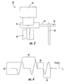
- FIG. 4 is a graphic illustration of an intermittent sinusoidal signal that controls the path of a laser during processing of an optical fiber in accordance with an exemplary embodiment of the present invention
- FIG. 5 is a schematic diagram illustrating the position of an optical fiber relative to a laser path in accordance with an exemplary embodiment of the present invention
- FIG. 6 is a schematic diagram illustrating a desired orientation of a laser in relation to an optical fiber processed in accordance with an exemplary embodiment of the present invention
- FIG. 7 is a magnified digital image of the endface of an optical fiber processed in accordance with an exemplary embodiment of the present invention and shown with light transmitted through the fiber core;
- FIG. 8 is a magnified digital image of the endface of an optical fiber mechanically cleaved in accordance with the prior art.
- FIG. 1 shows an exemplary embodiment of a field-installable connector 20 including a stub optical fiber 22 processed using a laser.
- the stub optical fiber 22 is cut and the endface 24 of the stub optical fiber 22 is shaped using a laser, such as a focused-beam CO 2 laser.
- the laser processed stub optical fiber 22 may replace a mechanically cleaved stub optical fiber in a field-installable connector.
- the stub optical fiber 22 may be of any fiber type known in the art, for example, a single-mode or multi-mode optical fiber comprising of a silica-based core and cladding surrounded by an outer coating of UV protective plastic material.
- the diameter of the inner core region in a single-mode fiber is about 8-10 ⁇ m, and in a multi-mode fiber is about 40-50 ⁇ m.
- the cladding region typically has an outer diameter of about 125 ⁇ m, and the cladding comprises a lower refractive index than the core region.
- the outer coating typically has an outer diameter of about 250 ⁇ m.
- the field optical fiber is brought into physical contact with the stub optical fiber 22 and held in place within a mechanical splice assembly, such as the UniCamTM mechanical splice assembly available from Corning Cable Systems LLC of Hickory, NC.
- the field-installable connector 20 comprises extremely accurate optical fiber alignment features operable for centering the field optical fiber relative to the stub optical fiber 22.
- an SC type field-installable connector 20 comprises a 2.5 mm ferrule 26 at one end of the stub optical fiber 22.
- the stub optical fiber 22 is secured within a longitudinally extending fiber bore 27 of the ferrule 26 and extends outwardly a predetermined distance beyond the rear face of the ferrule 26, for example from about 2 mm to about 15 mm, more preferably from about 5 mm to about 8 mm.
- a 2.5 mm ferrule 26 and related SC type connector 20 are shown, the ferrule and connector may be any other type including, but not limited to, ST, LC, FC, DC, MTP, MU and MT-RJ.
- Field-installable connector 20 further comprises a connector housing 28 in which the ferrule 26 resides.
- a biasing element such as a compression spring 30, is operable for permitting the ferrule 26 to float longitudinally within the connector housing 28. Limitations on the extent of the float of the ferrule 26 are determined by various factors, such as the amount of compression available from the compression spring 30 and the force required to compress the compression spring 30.
- the laser processed stub optical fiber 22 disposed within the ferrule 26 is inserted into a lengthwise extending alignment feature, for example a V-groove 31 ( FIG. 1 ), defmed by splice parts 32.
- the splice parts 32 are shown in a staggered configuration for purposes of clarity.
- the stub optical fiber 22 and the field optical fiber are brought into physical contact, end-to-end, within the splice parts 32.
- a substantially hollow ferrule holder 34 is provided for housing the splice parts 32.
- the ferrule holder 34 defines a lead-in tube 35 operable for guiding the field optical fiber into the ferrule holder 34 and between the splice parts 32.
- a collar 36 is positioned around the ferrule holder 34.
- a camming mechanism 38 defines a protrusion 40 that locks into a slot 41 provided on the forward end of the ferrule holder 34.
- the field-installable connector 20 is shown in its factory assembled configuration.
- the field optical fiber would be inserted into the opening defined by the lead-in tube 35 of the ferrule holder 34 and secured between the splice parts 32.
- the camming mechanism 38 is operable for applying pressure to a keel 39 ( FIG. 1 ) of the splice parts 32 in order to compress the splice parts 32 radially inward, as will be described.
- the camming mechanism 38 is rotated, which in turn applies the compressive force to the keel 39 of the splice parts 32.
- the field-installable connector 20 secures the stub optical fiber 22 and the field optical fiber in place. While the stub optical fiber 22 is laser processed, the field optical fiber is typically mechanically cleaved using conventional cleaving techniques.
- the field-installable connector 20 may be pre-assembled in the factory and mechanically spliced in the field to the field optical fiber to create a connectorized optical fiber cable.
- a rubber boot may be positioned over the rear of the connector 20 following assembly. The boot is operable for protecting and sealing the connector 20 and the mechanical splice from the environment, and/or limiting the bend radius of the field optical fiber extending rearwardly from the connector 20.
- FIG. 3 a schematic diagram illustrating an assembly 50 for rotating the ferrule 26 and consequently, the stub optical fiber 22 is shown.
- the ferrule 26 is positioned between a stationary ferrule support 52 defining an inverted V-groove (not shown) and a suitable spinning mechanism 54, such as a servo driven wheel or rotor.
- the stationary ferrule support 52 is representative of any known means operable for preventing upwards or sideways movement of the ferrule 26 during rotation.
- the spinning mechanism 54 is representative of any known means operable for rotating the ferrule 26 and the stub optical fiber 22 about the longitudinal axis of the ferrule 26, which at least in theory is coincident with the longitudinal axis of the stub optical fiber 22.
- the stationary ferrule holder 52 should provide support, without undue friction. In one example, the ferrule 26 is rotated at a rate of about 2 Hz.
- the free end of the stub optical fiber 22 is preferably supported by a second stationary support 58 comprising a V-groove (not shown) to minimize the effects of run-out during laser processing of the stub optical fiber 22.
- the portion of the stub optical fiber 22 protruding beyond the second stationary support 58 should be sufficiently long to permit laser processing the optical fiber 22, as will be described in greater detail below, yet not long enough to result in a significant eccentricity of rotation of the portion being cut and shaped.
- a laser beam is swept back and forth across the surface while the stub optical fiber 22 is rotating.
- the energy from a commercially available CO 2 laser such as a 150-watt maximum sealed tube CO 2 laser available from SYNRAD Inc. of Mukilteo, WA, is focused to a spot of about a 200 ⁇ m diameter.
- the laser may be focused to a spot slightly larger than the diameter of the stub optical fiber 22.
- the laser may be operated in a mode at a frequency of about 20 kHz. Referring to FIG. 4 , the oscillating motion of the laser may be driven by an intermittent sinusoidal signal that controls the path of the laser during processing.
- the frequency of the intermittent sinusoidal signal may be about 24 Hz, while the burst frequency may be about 12 Hz.
- the peak-to-peak amplitude of the sinusoidal signal is illustrated by reference numeral 60.
- the period of the burst frequency i.e., the time required to complete one full cycle of the laser processing
- reference numeral 62 The period of the sinusoidal signal frequency that controls the sweep of the laser (i.e., the time required to complete one full cycle of the laser sweep) is illustrated by reference numeral 64.
- the period of the dwell frequency i.e., the time between successive laser sweeps
- the period of the dwell frequency is also equal to the period of the burst frequency minus the period of the sinusoidal signal frequency.
- FIG. 5 is a schematic diagram illustrating the position of the stub optical fiber 22 relative to the sweep path 60 of the laser.
- the stub optical fiber 22 may be located from about 2 to about 2.5 fiber widths downward from the uppermost peak of the sinusoidal laser path, and about 8 to about 10 fiber widths upward from the null, or dwell, position 68 of the laser. This positioning produces two deposits of energy onto the stub optical fiber 22 followed by a cooling period before the next deposits of energy are applied.
- the burn mark of the laser is illustrated by reference numeral 66 and the cooling period of the laser sweep is illustrated by reference numeral 68.
- the peak-to-peak amplitude of the laser sweep is also illustrated by reference numeral 60 in FIG. 5 .
- Laser processing is achieved by impinging an amount of laser energy at the predetermined laser intensity, in the form of a Gaussian intensity distribution, onto the stub optical fiber 22.
- the radiation of the CO 2 laser is absorbed primarily at the outer surface of the fiber.
- the silica (i.e., glass) at the surface of the stub optical fiber 22 is raised above its vaporization temperature and is ablated away while heat is conducted into the material of the stub optical fiber 22. The longer the time the laser is maintained at the surface, the greater is the resulting depth penetration of the heat generated by the laser. Therefore, short, intense pulses may be used to cause ablation of the surface cladding with minimal melting of the underlying material.
- the pulse duration and energy intensity of the laser beam are preselected and periodically adjusted so that the optical fiber material of the stub optical fiber 22 is progressively ablated without re-depositing the ablated material or distorting the remaining optical fiber geometry.
- the laser processing methods disclosed herein permit an operator to produce an endface 24 on the stub optical fiber 22 while controlling the shape of the endface.
- the laser is swept in an oscillating motion across the stub optical fiber 22 to achieve ablation of the fiber material, while minimizing overheating from thermal energy in the non-ablated region.
- the process described herein may produce a slight flare to the outer diameter of the stub optical fiber 22. The impact of this flare is insignificant in the end product due to the fact that the mechanical splice assembly V-grooves may be a molded composite material that yields when clamped around the stub optical fiber 22.
- a convex, or dome shaped, endface with excellent symmetry is _ achieved by rotating the stub optical fiber 22 while pulsing the laser.
- the endface of the stub optical fiber 22 optimally comprises a dome shaped endface with a slightly protruding optical fiber core.
- FIG. 6 is a schematic diagram illustrating an exemplary orientation of the laser in relation to the stub optical fiber 22.
- the beam from a laser source 70 may be directed in the direction of the ferrule 26 at a desired angle ⁇ (i.e., 72 ) from about 10° to about 60° from perpendicular to the longitudinal axis of the stub optical fiber 22 so that the laser beam impinges the desired endface 24 of the stub optical fiber 22.
- the angle 72 may range from about 20° to about 45° from perpendicular to the longitudinal axis of the stub optical fiber 22.
- the angle 72 may range from about 25° to about 35° from perpendicular to the longitudinal axis of the stub optical fiber 22.
- the angle 72 is desired to overcome the approximate Gaussian energy distribution across the diameter of the laser beam.
- the angle 72 may be adjusted to produce a slightly dome shaped endface 24 of the stub optical fiber having a core protrusion of about 2 ⁇ m to about 3 ⁇ m. Due to heating and ablation effects, the endface 24 of the stub optical fiber 22 may have about a 5 ⁇ m to about 10 ⁇ m radius, which aids insertion of the stub optical fiber 22 into the alignment feature (i.e., a composite V-groove) of the mechanical splice assembly.
- the alignment feature i.e., a composite V-groove
- the optical fiber core leads the cladding material of the stub optical fiber 22.
- the protruding optical fiber core decreases the fiber core gap when the stub optical fiber 22 and the field optical fiber are butted together within the alignment feature of the mechanical splice assembly.
- another exemplary method for processing the endface 24 of a stub optical fiber 22 comprises fixing the position of the laser beam (i.e., no sweeping motion) and rotating the stub optical fiber 22.
- the laser may be pulsed at a frequency from about 8 Hz to about 12 Hz with a short pulse width in the micro-second range.
- the desired angle 72 between the beam of the laser and the stub optical fiber 22 may be within the ranges described previously.
- the most important parameter in this embodiment is the location of the stub optical fiber 22 relative to the focal point of the laser beam.
- the positional relationship should be both accurate and repeatable.
- the stub optical fiber 22 may be fixed in position (i.e., not rotated), and the laser beam may be swept across the fiber in the manner previously described.
- the laser may be run in a continuous mode and the sweeping parameters of the laser beam may also be the same as previously described.
- the laser may be placed up to about a meter or more from the stub optical fiber 22 to allow the beam to become more organized and the beam geometry more predictable.
- the accuracy and repeatability of the angle 72 of the laser beam with respect to the longitudinal axis of the stub optical fiber 22 is most important in achieving an acceptable result.
- the angle 72 may depend on the characteristics of the laser beam, including its cross-sectional energy profile.
- a conventional galvanometer and external drive may be used to sweep the laser beam while holding the stub optical fiber 22 stationary.
- Galvanometers are typically used in laser marking heads for sweeping the laser beam in 2 dimensions.
- the galvanometer (not shown) may be placed into the setup in conjunction with an IR scanning (F-theta) lens (not shown) to sweep the laser beam in the horizontal direction.
- a stepper motor (not shown) may still be used for positioning, without rotating, the ferrule 26 and the stub optical fiber 22.
- This stationary stub optical fiber 22 and laser beam sweep approach may also permit angles to be formed on the endface 24 of the stub optical fiber 22. Ribbon fibers may also benefit from this setup and laser processing method.
- the laser cutting and shaping methods of the present invention may be used to shape an individual optical fiber as well as a plurality of optical fibers oriented parallel to each other, for example the multiple fibers of an MT-RJ ferrule or a ribbon cable.
- the laser shaping process results in each optical fiber of the plurality of optical fibers having substantially the same dome shaped endface having a protruding optical fiber core.
- the laser process generates a generally convex endface having a radius from about 2 mm to about 20 mm, which minimizes the core gap in a mechanical splice even in situations in which a field optical fiber is cleaved at a slight angle.
- the laser process generates a convex endface, which aids insertion of the optical fiber(s), for example, into the V-groove 31 of the mechanical splice assembly previously described, while minimizing skiving.
- the laser cutting and shaping process of the present invention does not generate a microlens as described in U.S. Patent No. 4,932,959 , which would require both the cutting away of cladding material and melting the fiber core of the endface to form a lens curvature.
- the process may comprise the steps of: (1) loading a plurality of ferrules 26 into a pallet; (2) stripping each stub optical fiber 22; (3) inserting epoxy into each ferrule bore 27; (4) tacking the stub optical fiber 22 within the corresponding bore 27 of the ferrule 26; (5) cutting the stub optical fiber 22 to a predetermined length greater than the desired length of the finished stub optical fiber 22; (6) curing the epoxy; (7) laser scribing the stub optical fiber 22 close to the ferrule 26; (8) laser cutting and/or shaping the stub optical fiber 22 to produce a dome shaped endface 24; (9) inserting the ferrule 26 and the stub optical fiber 22 into a ferrule holder 34 and mechanical splice assembly 32; (10) inserting epoxy and curing; (11) inserting index-matching gel; (12) performing a hardware installation sequence depending on connector type; and (13) performing a sample end-line test.
- a laser cut-off station was used to process an optical fiber.
- An SC ferrule with about 2 mm of the ferrule ground away and a dry fiber running through the ferrule was used.
- the optical fiber was secured to the rear of the ferrule.
- a function generator was used to create a square-wave and control the pulse width of the laser. This allowed the laser to be fired for just one pulse.
- the optical fiber was impinged with a pulse of light at 0°, 90°, 180° and 270°.
- the pulse width was varied and it was found that the endface geometry can be controlled by the width of the pulse while holding all other variables constant.
- the amount of radial angle that the fiber was rotated was also varied before re-firing the laser.
- Tests were conducted firing the laser at 0°, 45°, 90°, 135°, 180°, 225°, 270° and 315° around the fiber. As the incremental angular value was decreased, the geometry of the fiber endface flattened in shape. Firing the laser at 0° and 180° created a wedge-shaped geometry endface. More control over the geometry of the endface was obtained by accurately supporting and rotating the optical fiber.
- the process described above was used to produce an endface surface within +/- 0.5° perpendicular to the axis of the optical fiber, and to place a round, or chamfer, along the edge of the fiber.
- the fiber was rotated while the cutting/shaping took place due to alignment issues.
- a small length of the optical fiber was placed in a ferrule supported by a V-groove.
- a stepper motor was controlled using a programmable logic controller (PLC).
- PLC programmable logic controller
- the end of the optical fiber protruded beyond a fiber support.
- the optical fiber was positioned at a preselected angle relative to the incoming pulsed laser beam.
- the ferrule was rotated at a rate of about 3 rev/second while the laser was pulsed at about 24 Hz with a pulse width of about 0.35 milliseconds.
- the ferrule completed about 20 revolutions during the laser processing.
- the resultant length of the optical fiber after laser processing was about 6 mm from the rear face of the ferrule.
- the laser used was a 50-watt CO 2 laser available from SYNRAD (model number 48-5). A 25-watt laser was also tested and found satisfactory for laser processing the optical fiber.
- the 50-watt laser operated at a 10.6 ⁇ m wavelength (mid-infrared) and was randomly polarized.
- the energy distribution in a cross-section of the beam was approximately Gaussian (TEM 00 ) with 95% purity. To the naked eye, the end of the optical fiber after laser processing appeared relatively flat.
- the endface of the optical fiber when viewed under digital magnification, included a rise in the core 74 of about 2 ⁇ m. The radius on the edge 76 of the fiber was about 5 ⁇ m.
- an optical fiber cleaved using a conventional mechanical cleaving technique is shown in FIG. 8 .
- defects 78 in the outer cladding region can be seen around the outer diameter of the optical fiber. The defects 78 were more pronounced at the location at which the mechanical cleaving blade made initial contact with the optical fiber.
- optical fiber processing methods and field-installable connector described above provide factory-produced assemblies that simplify conventional mechanical splicing in the field. Since no epoxy or crimps are needed to maintain the splice, the splice is not permanent and may be disassembled. A mechanical cleaver is not required to process the stub optical fiber, and field splicing is achieved without special fixtures or tools. Splicing may be accomplished one fiber at a time in applications in which multiple fibers are involved.
Landscapes
- Physics & Mathematics (AREA)
- Engineering & Computer Science (AREA)
- Optics & Photonics (AREA)
- Plasma & Fusion (AREA)
- Mechanical Engineering (AREA)
- General Physics & Mathematics (AREA)
- Mechanical Coupling Of Light Guides (AREA)
- Light Guides In General And Applications Therefor (AREA)
Abstract
Description
- The present invention relates to a method of fabricating a field-installable connector.
- Optical fibers are used for a variety of applications including voice communication, data transmission and the like. With the ever increasing and varied use of optical fibers, it is apparent that more efficient methods of splicing optical fibers are required. In order to effectively couple the signals transmitted between respective optical fibers, the method of splicing the optical fibers must not significantly attenuate, reduce or alter the transmitted signals. Currently, there are two common methods for splicing optical fibers: fusion splicing and mechanical splicing. Mechanical splicing, the method employed in the present invention, is a process for mating the ends of a pair of optical fibers in which the ends are brought into physical contact with each other and held in place by a mechanical force, such as a "cam" locking mechanism, a spring or a crimp.
- Conventional mechanical splicing methods typically involve filling any gap between the endfaces of the fibers, referred to herein as a "core gap," with a refractive index-matching gel. The gel acts as a medium that aids in the transfer of light between a pair of optical fibers, such as a field optical fiber and the stub optical fiber of a field-installable connector. Even though mechanical splices generally provide acceptable signal transmission characteristics, a mechanical splice can refract and/or disperse a portion of the transmitted signal so as to produce a corresponding return loss. The refractance and/or dispersion is/are due, at least in part, to differences between the respective indices of refraction of the cores of the field optical fiber and the stub optical fiber stub, and the index of refraction of the air in the core gap. The index of refraction of the index-matching gel is selected to match the indices of refraction of the cores of the fibers, and thereby reduce or eliminate the difference between the indices of refraction of the cores of the fibers and the core gap.
- To create a conventional mechanical splice, the ends of two optical fibers are typically cleaved and inserted into a mechanical splice assembly having precision fiber alignment features, such as machined or etched "V-grooves" extending longitudinally through the assembly. The number of V-grooves and their respective dimensions are of a size to permit the fibers to rest securely within the assembly. The fibers are cleaved using a mechanical cleaver that produces a substantially flat fiber endface essentially perpendicular to the longitudinal axis of the fiber. Mechanical cleaves/cleavers suffer from several disadvantages. First, mechanical cleaves have an inherent glass defect zone that is a result of the mechanical blade striking the glass fiber. Second, mechanical cleavers typically produce sharp edges between the cleaved endface and the outer diameter of the fiber. This sharp edge can skive the V-grooves of the mechanical splice assembly. Third, mechanical cleavers typically produce substantially flat fiber endfaces with cleave angles that may not be perpendicular to the longitudinal axis of the fiber. The cleave angle may increase the core gap that results when two cleaved fibers are butted together in the mechanical splice assembly without regard for the orientation of their cleave angles, which increases attenuation. In addition to these disadvantages, mechanical cleavers require periodic replacement of the cleaver blade and are not conducive to automation due to long-term instability.
- It is known to use a focused relatively low-power laser beam to cut an optical fiber or to fuse together a pair of optical fibers. The use of a laser for processing optical fibers is repeatable and conducive to automation. Laser processing of optical fibers is also known to produce an optical fiber endface that is substantially free of defects, as compared to optical fibers that have been mechanically cleaved. Accordingly, it would be desirable to process a stub optical fiber of a field-installable connector using a laser to overcome at least some of the disadvantages described above. In particular, it would be desirable to laser process the stub optical fiber of a field-installable connector to produce a convex endface substantially free of defects and having an edge radius that aids fiber insertion into a mechanical splice assembly, thus minimizing skiving of alignment features. It would also be desirable to laser process the stub optical fiber to thereby minimize the core gap in a mechanical splice, even in applications in which a field prepared fiber has an endface with a slight angle relative to its longitudinal axis. Further, the laser process should expend no consumables and be automation friendly and stable.
- The prior art document
US 2003/152333 A1 discloses a field-installable connector comprising a connector housing; a ferrule having front and rear opposed faces and at least one fiber bore defined longitudinally therethrough; and a stub optical fiber having a laser processed endface disposed within the at least one fiber bore of the ferrule and extending a predetermined distance outwardly beyond the rear face. The prior art documentWO 03/056372 A US 2002/159717 A1 ,US 2002/175151 A1 US-A-6139196 andEP-A-0 391 598 . - The present invention provides a method of fabricating a field-installable connector adapted to be mechanically spliced to a field optical fiber, comprising the following steps: rotating a stub optical fiber secured within a ferrule of the field-installable connector; laser processing the stub optical fiber to create an endface by sweeping a laser beam directed at a preselected angle from perpendicular to a longitudinal axis of the stub optical fiber back and forth across a surface of the rotating stub optical fiber; wherein an oscillating motion of the laser is driven by an intermittent sinusoidal signal resulting in at least one deposit of energy onto the stub optical fiber followed by a cooling period before a subsequent deposit of energy occurs; and wherein a pulse duration and a laser energy are predetermined so that the stub optical fiber is progressively ablated without re-depositing ablated material or distorting the geometry of the remaining stub optical fiber.
- In a exemplary embodiment, an oscillating motion of the laser may be driven by an intermittent sinusoidal signal resulting in two deposits of laser energy onto the stub optical fiber followed by a cooling period before the next deposits of laser energy occur. The pulse duration and intensity of the laser energy may be preselected and adjusted so that optical fiber material is progressively ablated without re-depositing the ablated material or distorting the remaining fiber geometry.
- In a still further exemplary embodiment, the present invention is a method of laser processing an optical fiber to produce a convex, or dome shaped, endface. The method comprises rotating the optical fiber while sweeping a beam of a laser desired at a preselected angle from perpendicular to the longitudinal axis of the optical fiber back and forth across the rotating optical fiber. As in the embodiment previously described, the oscillating motion of the laser may be driven by an intermittent sinusoidal signal resulting in two deposits of energy onto the optical fiber followed by a cooling period before the next deposits of energy occur, and the pulse duration and the intensity of the laser energy may be predetermined and adjusted so that optical fiber material is progressively ablated without re-depositing the ablated material or distorting the remaining optical fiber geometry. The preselected angle may range from about 10° to about 60°, and more preferably, from about 25° to about 35°. In particular, the laser processing comprises cutting and shaping an optical fiber to create a dome shaped endface having a protruding fiber core.
- Thee and other features, aspects and advantages of the present invention are better understood when the following detailed description of the invention is read with reference to the accompanying drawings, in which:
-
FIG. 1 is an exploded perspective view of a field-installable connector including a stub optical fiber having a laser shaped endface in accordance with an exemplary embodiment of the present invention; -
FIG. 2 is a cut-away perspective view of the connector ofFIG. 1 shown in its assembled configuration; -
FIG. 3 is a schematic diagram illustrating a stub optical fiber and ferrule assembly processed with a focused, relatively low-energy laser in accordance with an exemplary embodiment of the present invention; -
FIG. 4 is a graphic illustration of an intermittent sinusoidal signal that controls the path of a laser during processing of an optical fiber in accordance with an exemplary embodiment of the present invention; -
FIG. 5 is a schematic diagram illustrating the position of an optical fiber relative to a laser path in accordance with an exemplary embodiment of the present invention; -
FIG. 6 is a schematic diagram illustrating a desired orientation of a laser in relation to an optical fiber processed in accordance with an exemplary embodiment of the present invention; -
FIG. 7 is a magnified digital image of the endface of an optical fiber processed in accordance with an exemplary embodiment of the present invention and shown with light transmitted through the fiber core; and -
FIG. 8 is a magnified digital image of the endface of an optical fiber mechanically cleaved in accordance with the prior art. - The present invention will now be described more fully hereinafter with reference to the accompanying drawings in which exemplary embodiments of the invention are shown. However, this invention may be embodied in many different forms and should not be construed as limited to the embodiments set forth herein. These exemplary embodiments are provided so that this disclosure will be both thorough and complete, and will fully convey the scope of the invention to those skilled in the art. Like reference numbers refer to like elements throughout the various drawings.
- Referring now to the drawings,
FIG. 1 shows an exemplary embodiment of a field-installable connector 20 including a stuboptical fiber 22 processed using a laser. In particular, the stuboptical fiber 22 is cut and theendface 24 of the stuboptical fiber 22 is shaped using a laser, such as a focused-beam CO2 laser. The laser processed stuboptical fiber 22 may replace a mechanically cleaved stub optical fiber in a field-installable connector. The stuboptical fiber 22 may be of any fiber type known in the art, for example, a single-mode or multi-mode optical fiber comprising of a silica-based core and cladding surrounded by an outer coating of UV protective plastic material. The diameter of the inner core region in a single-mode fiber is about 8-10 µm, and in a multi-mode fiber is about 40-50 µm. The cladding region typically has an outer diameter of about 125 µm, and the cladding comprises a lower refractive index than the core region. The outer coating typically has an outer diameter of about 250 µm. In the field, the end portion of a field optical fiber (not shown) to which theconnector 20 is to be connected, is inserted into theconnector 20 from the end opposite the stuboptical fiber 22. The field optical fiber is brought into physical contact with the stuboptical fiber 22 and held in place within a mechanical splice assembly, such as the UniCam™ mechanical splice assembly available from Corning Cable Systems LLC of Hickory, NC. The field-installable connector 20 comprises extremely accurate optical fiber alignment features operable for centering the field optical fiber relative to the stuboptical fiber 22. - As shown in the
FIG. 1 , an SC type field-installable connector 20 comprises a 2.5mm ferrule 26 at one end of the stuboptical fiber 22. The stuboptical fiber 22 is secured within a longitudinally extending fiber bore 27 of theferrule 26 and extends outwardly a predetermined distance beyond the rear face of theferrule 26, for example from about 2 mm to about 15 mm, more preferably from about 5 mm to about 8 mm. Although a 2.5mm ferrule 26 and relatedSC type connector 20 are shown, the ferrule and connector may be any other type including, but not limited to, ST, LC, FC, DC, MTP, MU and MT-RJ. Once secured within theferrule 26, the stuboptical fiber 22 is processed with a laser in a manner that will be described hereinafter. Although the stuboptical fiber 22 may be processed with a laser prior to being secured within theferrule 26, it is preferable to process the stuboptical fiber 22 after being secured to more easily and repeatably control the predetermined distance that the stuboptical fiber 22 extends beyond the rear face of theferrule 26. Field-installable connector 20 further comprises aconnector housing 28 in which theferrule 26 resides. A biasing element, such as acompression spring 30, is operable for permitting theferrule 26 to float longitudinally within theconnector housing 28. Limitations on the extent of the float of theferrule 26 are determined by various factors, such as the amount of compression available from thecompression spring 30 and the force required to compress thecompression spring 30. - Referring to
FIG. 2 , the laser processed stuboptical fiber 22 disposed within theferrule 26 is inserted into a lengthwise extending alignment feature, for example a V-groove 31 (FIG. 1 ), defmed bysplice parts 32. InFIG. 1 , thesplice parts 32 are shown in a staggered configuration for purposes of clarity. The stuboptical fiber 22 and the field optical fiber are brought into physical contact, end-to-end, within thesplice parts 32. A substantiallyhollow ferrule holder 34 is provided for housing thesplice parts 32. Theferrule holder 34 defines a lead-intube 35 operable for guiding the field optical fiber into theferrule holder 34 and between thesplice parts 32. Acollar 36 is positioned around theferrule holder 34. Acamming mechanism 38 defines aprotrusion 40 that locks into aslot 41 provided on the forward end of theferrule holder 34. - Referring to
FIG. 2 , the field-installable connector 20 is shown in its factory assembled configuration. Although not shown, the field optical fiber would be inserted into the opening defined by the lead-intube 35 of theferrule holder 34 and secured between thesplice parts 32. Thecamming mechanism 38 is operable for applying pressure to a keel 39 (FIG. 1 ) of thesplice parts 32 in order to compress thesplice parts 32 radially inward, as will be described. Once the stuboptical fiber 22 and the field optical fiber have been brought into physical contact, thecamming mechanism 38 is rotated, which in turn applies the compressive force to thekeel 39 of thesplice parts 32. Once the mechanical splice is produced, the field-installable connector 20 secures the stuboptical fiber 22 and the field optical fiber in place. While the stuboptical fiber 22 is laser processed, the field optical fiber is typically mechanically cleaved using conventional cleaving techniques. The field-installable connector 20 may be pre-assembled in the factory and mechanically spliced in the field to the field optical fiber to create a connectorized optical fiber cable. Although not shown, a rubber boot may be positioned over the rear of theconnector 20 following assembly. The boot is operable for protecting and sealing theconnector 20 and the mechanical splice from the environment, and/or limiting the bend radius of the field optical fiber extending rearwardly from theconnector 20. - Referring to
FIG. 3 , a schematic diagram illustrating anassembly 50 for rotating theferrule 26 and consequently, the stuboptical fiber 22 is shown. To provide for rotation of the stuboptical fiber 22 about its longitudinal axis, theferrule 26 is positioned between astationary ferrule support 52 defining an inverted V-groove (not shown) and asuitable spinning mechanism 54, such as a servo driven wheel or rotor. Thestationary ferrule support 52 is representative of any known means operable for preventing upwards or sideways movement of theferrule 26 during rotation. Thespinning mechanism 54 is representative of any known means operable for rotating theferrule 26 and the stuboptical fiber 22 about the longitudinal axis of theferrule 26, which at least in theory is coincident with the longitudinal axis of the stuboptical fiber 22. Thestationary ferrule holder 52 should provide support, without undue friction. In one example, theferrule 26 is rotated at a rate of about 2 Hz. The free end of the stuboptical fiber 22 is preferably supported by a secondstationary support 58 comprising a V-groove (not shown) to minimize the effects of run-out during laser processing of the stuboptical fiber 22. The portion of the stuboptical fiber 22 protruding beyond the secondstationary support 58 should be sufficiently long to permit laser processing theoptical fiber 22, as will be described in greater detail below, yet not long enough to result in a significant eccentricity of rotation of the portion being cut and shaped. - In an exemplary method of laser processing the stub
optical fiber 22, a laser beam is swept back and forth across the surface while the stuboptical fiber 22 is rotating. The energy from a commercially available CO2 laser, such as a 150-watt maximum sealed tube CO2 laser available from SYNRAD Inc. of Mukilteo, WA, is focused to a spot of about a 200 µm diameter. In one embodiment, the laser may be focused to a spot slightly larger than the diameter of the stuboptical fiber 22. The laser may be operated in a mode at a frequency of about 20 kHz. Referring toFIG. 4 , the oscillating motion of the laser may be driven by an intermittent sinusoidal signal that controls the path of the laser during processing. The frequency of the intermittent sinusoidal signal may be about 24 Hz, while the burst frequency may be about 12 Hz. The peak-to-peak amplitude of the sinusoidal signal is illustrated byreference numeral 60. The period of the burst frequency (i.e., the time required to complete one full cycle of the laser processing) is illustrated byreference numeral 62. The period of the sinusoidal signal frequency that controls the sweep of the laser (i.e., the time required to complete one full cycle of the laser sweep) is illustrated byreference numeral 64. The period of the dwell frequency (i.e., the time between successive laser sweeps) is illustrated byreference numeral 68. The period of the dwell frequency is also equal to the period of the burst frequency minus the period of the sinusoidal signal frequency. -
FIG. 5 is a schematic diagram illustrating the position of the stuboptical fiber 22 relative to thesweep path 60 of the laser. In one embodiment, the stuboptical fiber 22 may be located from about 2 to about 2.5 fiber widths downward from the uppermost peak of the sinusoidal laser path, and about 8 to about 10 fiber widths upward from the null, or dwell,position 68 of the laser. This positioning produces two deposits of energy onto the stuboptical fiber 22 followed by a cooling period before the next deposits of energy are applied. The burn mark of the laser is illustrated byreference numeral 66 and the cooling period of the laser sweep is illustrated byreference numeral 68. The peak-to-peak amplitude of the laser sweep is also illustrated byreference numeral 60 inFIG. 5 . - Laser processing is achieved by impinging an amount of laser energy at the predetermined laser intensity, in the form of a Gaussian intensity distribution, onto the stub
optical fiber 22. Upon contact with the stuboptical fiber 22, the radiation of the CO2 laser is absorbed primarily at the outer surface of the fiber. The silica (i.e., glass) at the surface of the stuboptical fiber 22 is raised above its vaporization temperature and is ablated away while heat is conducted into the material of the stuboptical fiber 22. The longer the time the laser is maintained at the surface, the greater is the resulting depth penetration of the heat generated by the laser. Therefore, short, intense pulses may be used to cause ablation of the surface cladding with minimal melting of the underlying material. The pulse duration and energy intensity of the laser beam are preselected and periodically adjusted so that the optical fiber material of the stuboptical fiber 22 is progressively ablated without re-depositing the ablated material or distorting the remaining optical fiber geometry. The laser processing methods disclosed herein permit an operator to produce anendface 24 on the stuboptical fiber 22 while controlling the shape of the endface. - Preferably, the laser is swept in an oscillating motion across the stub
optical fiber 22 to achieve ablation of the fiber material, while minimizing overheating from thermal energy in the non-ablated region. The process described herein may produce a slight flare to the outer diameter of the stuboptical fiber 22. The impact of this flare is insignificant in the end product due to the fact that the mechanical splice assembly V-grooves may be a molded composite material that yields when clamped around the stuboptical fiber 22. A convex, or dome shaped, endface with excellent symmetry is _ achieved by rotating the stuboptical fiber 22 while pulsing the laser. In the case of a stationary stuboptical fiber 22, a dome shaped endface with elongated symmetry may result. In either case, the endface of the stuboptical fiber 22 optimally comprises a dome shaped endface with a slightly protruding optical fiber core. -
FIG. 6 is a schematic diagram illustrating an exemplary orientation of the laser in relation to the stuboptical fiber 22. The beam from alaser source 70 may be directed in the direction of theferrule 26 at a desired angle θ (i.e., 72) from about 10° to about 60° from perpendicular to the longitudinal axis of the stuboptical fiber 22 so that the laser beam impinges the desiredendface 24 of the stuboptical fiber 22. In a preferred embodiment, theangle 72 may range from about 20° to about 45° from perpendicular to the longitudinal axis of the stuboptical fiber 22. In a more preferred embodiment, theangle 72 may range from about 25° to about 35° from perpendicular to the longitudinal axis of the stuboptical fiber 22. Theangle 72 is desired to overcome the approximate Gaussian energy distribution across the diameter of the laser beam. Theangle 72 may be adjusted to produce a slightly dome shapedendface 24 of the stub optical fiber having a core protrusion of about 2 µm to about 3 µm. Due to heating and ablation effects, theendface 24 of the stuboptical fiber 22 may have about a 5 µm to about 10 µm radius, which aids insertion of the stuboptical fiber 22 into the alignment feature (i.e., a composite V-groove) of the mechanical splice assembly. By producing a stuboptical fiber 22 having a dome shapedendface 24, the optical fiber core leads the cladding material of the stuboptical fiber 22. The protruding optical fiber core decreases the fiber core gap when the stuboptical fiber 22 and the field optical fiber are butted together within the alignment feature of the mechanical splice assembly. - In an alternative embodiment, another exemplary method for processing the
endface 24 of a stuboptical fiber 22 comprises fixing the position of the laser beam (i.e., no sweeping motion) and rotating the stuboptical fiber 22. The laser may be pulsed at a frequency from about 8 Hz to about 12 Hz with a short pulse width in the micro-second range. The desiredangle 72 between the beam of the laser and the stuboptical fiber 22 may be within the ranges described previously. The most important parameter in this embodiment is the location of the stuboptical fiber 22 relative to the focal point of the laser beam. The positional relationship should be both accurate and repeatable. Although this process may produce similar results to the process described previously, automating the process is somewhat more difficult. - In another exemplary embodiment, the stub
optical fiber 22 may be fixed in position (i.e., not rotated), and the laser beam may be swept across the fiber in the manner previously described. The laser may be run in a continuous mode and the sweeping parameters of the laser beam may also be the same as previously described. In one example, the laser may be placed up to about a meter or more from the stuboptical fiber 22 to allow the beam to become more organized and the beam geometry more predictable. The accuracy and repeatability of theangle 72 of the laser beam with respect to the longitudinal axis of the stuboptical fiber 22 is most important in achieving an acceptable result. Theangle 72 may depend on the characteristics of the laser beam, including its cross-sectional energy profile. A conventional galvanometer and external drive may be used to sweep the laser beam while holding the stuboptical fiber 22 stationary. Galvanometers are typically used in laser marking heads for sweeping the laser beam in 2 dimensions. The galvanometer (not shown) may be placed into the setup in conjunction with an IR scanning (F-theta) lens (not shown) to sweep the laser beam in the horizontal direction. A stepper motor (not shown) may still be used for positioning, without rotating, theferrule 26 and the stuboptical fiber 22. This stationary stuboptical fiber 22 and laser beam sweep approach may also permit angles to be formed on theendface 24 of the stuboptical fiber 22. Ribbon fibers may also benefit from this setup and laser processing method. - The laser cutting and shaping methods of the present invention may be used to shape an individual optical fiber as well as a plurality of optical fibers oriented parallel to each other, for example the multiple fibers of an MT-RJ ferrule or a ribbon cable. The laser shaping process results in each optical fiber of the plurality of optical fibers having substantially the same dome shaped endface having a protruding optical fiber core. The laser process generates a generally convex endface having a radius from about 2 mm to about 20 mm, which minimizes the core gap in a mechanical splice even in situations in which a field optical fiber is cleaved at a slight angle. In addition, the laser process generates a convex endface, which aids insertion of the optical fiber(s), for example, into the V-
groove 31 of the mechanical splice assembly previously described, while minimizing skiving. The laser cutting and shaping process of the present invention does not generate a microlens as described inU.S. Patent No. 4,932,959 , which would require both the cutting away of cladding material and melting the fiber core of the endface to form a lens curvature. - In an exemplary embodiment for fiber processing automation, the process may comprise the steps of: (1) loading a plurality of
ferrules 26 into a pallet; (2) stripping each stuboptical fiber 22; (3) inserting epoxy into each ferrule bore 27; (4) tacking the stuboptical fiber 22 within the corresponding bore 27 of theferrule 26; (5) cutting the stuboptical fiber 22 to a predetermined length greater than the desired length of the finished stuboptical fiber 22; (6) curing the epoxy; (7) laser scribing the stuboptical fiber 22 close to theferrule 26; (8) laser cutting and/or shaping the stuboptical fiber 22 to produce a dome shapedendface 24; (9) inserting theferrule 26 and the stuboptical fiber 22 into aferrule holder 34 andmechanical splice assembly 32; (10) inserting epoxy and curing; (11) inserting index-matching gel; (12) performing a hardware installation sequence depending on connector type; and (13) performing a sample end-line test. In alternative embodiments, either of the epoxy steps may be replaced by ultrasonic welds and/or press fits. - Experimental results: A laser cut-off station was used to process an optical fiber. An SC ferrule with about 2 mm of the ferrule ground away and a dry fiber running through the ferrule was used. The optical fiber was secured to the rear of the ferrule. A function generator was used to create a square-wave and control the pulse width of the laser. This allowed the laser to be fired for just one pulse. The optical fiber was impinged with a pulse of light at 0°, 90°, 180° and 270°. The pulse width was varied and it was found that the endface geometry can be controlled by the width of the pulse while holding all other variables constant. The amount of radial angle that the fiber was rotated was also varied before re-firing the laser. Tests were conducted firing the laser at 0°, 45°, 90°, 135°, 180°, 225°, 270° and 315° around the fiber. As the incremental angular value was decreased, the geometry of the fiber endface flattened in shape. Firing the laser at 0° and 180° created a wedge-shaped geometry endface. More control over the geometry of the endface was obtained by accurately supporting and rotating the optical fiber.
- The process described above was used to produce an endface surface within +/- 0.5° perpendicular to the axis of the optical fiber, and to place a round, or chamfer, along the edge of the fiber. In the preferred embodiment for laser processing a single optical fiber, the fiber was rotated while the cutting/shaping took place due to alignment issues. A small length of the optical fiber was placed in a ferrule supported by a V-groove. A stepper motor was controlled using a programmable logic controller (PLC). The end of the optical fiber protruded beyond a fiber support. The optical fiber was positioned at a preselected angle relative to the incoming pulsed laser beam. In one example, the ferrule was rotated at a rate of about 3 rev/second while the laser was pulsed at about 24 Hz with a pulse width of about 0.35 milliseconds. The ferrule completed about 20 revolutions during the laser processing. The resultant length of the optical fiber after laser processing was about 6 mm from the rear face of the ferrule. In one example, the laser used was a 50-watt CO2 laser available from SYNRAD (model number 48-5). A 25-watt laser was also tested and found satisfactory for laser processing the optical fiber. The 50-watt laser operated at a 10.6 µm wavelength (mid-infrared) and was randomly polarized. The energy distribution in a cross-section of the beam was approximately Gaussian (TEM00) with 95% purity. To the naked eye, the end of the optical fiber after laser processing appeared relatively flat.
- Referring to
FIG. 7 , when viewed under digital magnification, the endface of the optical fiber included a rise in thecore 74 of about 2 µm. The radius on theedge 76 of the fiber was about 5 µm. In contrast, an optical fiber cleaved using a conventional mechanical cleaving technique is shown inFIG. 8 . When viewed under digital magnification,defects 78 in the outer cladding region can be seen around the outer diameter of the optical fiber. Thedefects 78 were more pronounced at the location at which the mechanical cleaving blade made initial contact with the optical fiber. - The optical fiber processing methods and field-installable connector described above provide factory-produced assemblies that simplify conventional mechanical splicing in the field. Since no epoxy or crimps are needed to maintain the splice, the splice is not permanent and may be disassembled. A mechanical cleaver is not required to process the stub optical fiber, and field splicing is achieved without special fixtures or tools. Splicing may be accomplished one fiber at a time in applications in which multiple fibers are involved.
Claims (7)
- A method of fabricating a field-installable connector adapted to be mechanically spliced to a field optical fiber, comprising:rotating a stub optical fiber secured within a ferrule of the field-installable connector;laser processing the stub optical fiber to create an endface by sweeping a laser beam directed at a preselected angle from perpendicular to a longitudinal axis of the stub optical fiber back and forth across a surface of the rotating stub optical fiber, andwherein an oscillating motion of the laser is driven by an intermittent sinusoidal signal resulting in at least one deposit of energy onto the stub optical fiber followed by a cooling period before a subsequent deposit of energy occurs; andwherein a pulse duration and a laser energy are predetermined so that the stub optical fiber is progressively ablated without re-depositing ablated material or distorting the geometry of the remaining stub optical fiber.
- The method of claim 1, wherein the preselected angle ranges from about 10° to about 60° from perpendicular to the longitudinal axis of the stub optical fiber.
- The method of claim 1, wherein the preselected angle ranges from about 25° to about 35° from perpendicular to the longitudinal axis of the stub optical fiber.
- The method of claim 1, wherein the laser is focused to a spot size that is slightly larger than the diameter of the stub optical fiber.
- The method of claim 1, wherein the stub optical fiber is positioned from about 2 to about 2.5 fiber widths downward from an uppermost peak of a sinusoidal laser path and about 8 to about 10 fiber widths upward from a dwell position of the laser.
- The method of claim 1, wherein the step of laser processing the stub optical fiber is achieved by impinging an amount of laser energy at a preselected laser intensity in the form of a Gaussian intensity distribution onto the stub optical fiber.
- The method of claim 1, wherein the step of laser processing the stub optical fiber creates a dome shaped endface having a protruding fiber core.
Applications Claiming Priority (2)
| Application Number | Priority Date | Filing Date | Title |
|---|---|---|---|
| US10/698,220 US7216512B2 (en) | 2003-10-31 | 2003-10-31 | Method of making an optical fiber by laser cleaving |
| PCT/US2004/035938 WO2005045494A1 (en) | 2003-10-31 | 2004-10-28 | Field-installable connector including stub optical fiber having laser shaped endface |
Publications (2)
| Publication Number | Publication Date |
|---|---|
| EP1678537A1 EP1678537A1 (en) | 2006-07-12 |
| EP1678537B1 true EP1678537B1 (en) | 2010-08-25 |
Family
ID=34550575
Family Applications (1)
| Application Number | Title | Priority Date | Filing Date |
|---|---|---|---|
| EP04818328A Expired - Lifetime EP1678537B1 (en) | 2003-10-31 | 2004-10-28 | Method of fabrication of a field-installable fibre optic connector including a stub optical fibre |
Country Status (8)
| Country | Link |
|---|---|
| US (1) | US7216512B2 (en) |
| EP (1) | EP1678537B1 (en) |
| CN (1) | CN100573207C (en) |
| AT (1) | ATE479122T1 (en) |
| AU (1) | AU2004287170B2 (en) |
| CA (1) | CA2543682C (en) |
| DE (1) | DE602004028852D1 (en) |
| WO (1) | WO2005045494A1 (en) |
Families Citing this family (87)
| Publication number | Priority date | Publication date | Assignee | Title |
|---|---|---|---|---|
| US7204644B2 (en) | 2004-03-24 | 2007-04-17 | Corning Cable Systems Llc | Field installable optical fiber connector |
| US20050213897A1 (en) * | 2004-03-29 | 2005-09-29 | Palmer Jeffrey D | Field-installable fusion spliced fiber optic connector kits and methods therefor |
| ATE535976T1 (en) | 2004-08-27 | 2011-12-15 | Prysmian Telecom Cables & Systems Australia Pty Ltd | SYSTEM AND APPARATUS FOR TRANSPORTING FIBER OPTICAL CABLE ALONG A PASSAGE |
| US20060137403A1 (en) * | 2004-12-29 | 2006-06-29 | Barr Brian D | High energy fiber terminations and methods |
| JP4942327B2 (en) * | 2005-10-28 | 2012-05-30 | スリーエム イノベイティブ プロパティズ カンパニー | Optical connector |
| US7264403B1 (en) | 2006-05-02 | 2007-09-04 | Corning Cable Systems Llc | Optical ferrule having a covering and associated method of ablating an optical fiber |
| RU2460100C2 (en) * | 2006-11-13 | 2012-08-27 | Сумитомо Электрик Индастриз, Лтд. | Holder, fusion splicing apparatus and method of assembling optical connector |
| WO2008070006A2 (en) * | 2006-12-01 | 2008-06-12 | Applied Optical Systems, Inc. | Quick terminated fiber optic termini and fiber optic cable, and method for making |
| BRPI0807941A2 (en) | 2007-02-16 | 2014-07-01 | 3M Innovative Proprietes Company | DISTANCE GRIP OPTICAL FIBER CONNECTOR |
| US20090041412A1 (en) * | 2007-08-07 | 2009-02-12 | Jeffrey Dean Danley | Laser erosion processes for fiber optic ferrules |
| US7513695B1 (en) * | 2007-10-09 | 2009-04-07 | Protai Photonic Co., Ltd. | Small form factor, field-installable optical fiber connector |
| US7708469B2 (en) * | 2008-04-11 | 2010-05-04 | Corning Cable Systems Llc | Fiber optic connector assembly and method for venting gas inside a fiber optic connector sub-assembly |
| US8109679B2 (en) | 2008-11-25 | 2012-02-07 | Corning Cable Systems Llc | Optical ferrule assemblies and methods of making the same |
| WO2010080793A2 (en) | 2009-01-09 | 2010-07-15 | Hillcrest Laboratories, Inc. | Zooming and panning widget for internet browsers |
| WO2010104611A1 (en) | 2009-03-11 | 2010-09-16 | Exxonmobil Chemical Patents Inc. | Tire innerliners having improved cold temperature properties |
| EP2409188A2 (en) * | 2009-03-17 | 2012-01-25 | ADC Telecommunications, Inc. | Method of directly molding ferrule on fiber optic cable |
| WO2010118106A1 (en) | 2009-04-07 | 2010-10-14 | Afl Telecommunications Llc | Method and apparatus for cleaving and chamfering optical fiber |
| KR20120030375A (en) * | 2009-04-23 | 2012-03-28 | 쓰리엠 이노베이티브 프로퍼티즈 컴파니 | Collar body for field terminable optical connector |
| US8340485B2 (en) * | 2009-05-29 | 2012-12-25 | Corning Cable Systems Llc | Laser-shaped optical fibers along with optical assemblies and methods therefor |
| CN102630306B (en) | 2009-11-24 | 2015-11-25 | 康宁光缆系统有限责任公司 | Methods of preparing optical fibers and placing optical fibers in blind vias, as well as related assemblies and methods of manufacturing assemblies |
| CN102713704A (en) | 2010-01-15 | 2012-10-03 | 康宁光缆系统有限责任公司 | Fiber optic connector of a fiber optic connection termination system |
| EP2558892A2 (en) | 2010-04-16 | 2013-02-20 | ADC Telecommunications, Inc. | Fiber optic cable assembly and method of making the same |
| US8616783B2 (en) * | 2010-04-26 | 2013-12-31 | Corning Cable Systems Llc | Fiber optic assemblies having connectors with recessed optical fibers |
| KR101087037B1 (en) * | 2010-12-06 | 2011-11-25 | 주식회사 에이제이월드 | Tool and protective case for mechanical splice |
| US8506178B2 (en) | 2011-06-24 | 2013-08-13 | Go!Foton Holdings, Inc. | Mechanical splicer apparatus for fiber optic cables |
| US8494331B2 (en) | 2011-07-06 | 2013-07-23 | Go!Foton Holdings, Inc. | Apparatus and method for mass producing optical fiber splice-on connector subunits |
| US8506179B2 (en) | 2011-07-21 | 2013-08-13 | Go!Foton Holdings, Inc. | Deformable plastic radially symmetric mechanical splicers and connectors for optical fibers |
| WO2013077969A1 (en) | 2011-11-23 | 2013-05-30 | Adc Telecommunications, Inc. | Multi-fiber fiber optic connector |
| US9205609B1 (en) | 2011-12-21 | 2015-12-08 | Corning Cable Systems Llc | Laser cutting and polishing methods for optical fibers and fibers resulting |
| US9268102B2 (en) | 2012-02-07 | 2016-02-23 | Tyco Electronics Raychem Bvba | Cable termination assembly and method for connectors |
| CA2864886A1 (en) | 2012-02-20 | 2013-08-29 | Adc Telecommunications, Inc. | Fiber optic connector, fiber optic connector and cable assembly, and methods for manufacturing |
| US8764314B2 (en) | 2012-06-15 | 2014-07-01 | Corning Cable Systems Llc | Optical fiber and composite inorganic ferrule assemblies and methods |
| US8985866B2 (en) | 2012-06-20 | 2015-03-24 | Corning Cable Systems Llc | Simultaneous thermal forming of ferrule and optical fiber in a ferrule assembly to thermally form an optical surface in the ferrule assembly, and related fiber optic components, fiber connectors, assemblies, and methods |
| US9205610B1 (en) | 2012-09-17 | 2015-12-08 | Corning Cable Systems Llc | Head-on laser shaping of optical surfaces of optical fibers, and related assemblies and methods |
| US8939654B2 (en) | 2012-09-27 | 2015-01-27 | Adc Telecommunications, Inc. | Ruggedized multi-fiber fiber optic connector with sealed dust cap |
| US9500830B2 (en) | 2012-09-28 | 2016-11-22 | Commscope Technologies Llc | Splice-on cable breakout assembly |
| US9897764B2 (en) | 2012-09-28 | 2018-02-20 | Commscope Technologies Llc | Molded ferrules for optical fibers |
| US8696215B1 (en) | 2012-10-15 | 2014-04-15 | Corning Cable Systems Llc | Adhesive compositions including partially cross-linked resins and coupling agents and methods for use thereof |
| US8840318B2 (en) | 2012-10-15 | 2014-09-23 | Corning Cable Systems Llc | Ferrule with stress-isolation feature |
| US9568686B2 (en) | 2012-10-15 | 2017-02-14 | Corning Optical Communications LLC | Optical connector and ferrule adhesion system including adhesive composition, and related methods |
| US9039295B2 (en) | 2012-10-15 | 2015-05-26 | Corning Cable Systems Llc | Adhesive compositions including partially cross-linked resins and thermoset resins and methods for use thereof |
| US9880362B2 (en) | 2012-10-22 | 2018-01-30 | Corning Optical Communications LLC | Methods of securing one or more optical fibers to a ferrule |
| US9322998B2 (en) * | 2013-01-15 | 2016-04-26 | Corning Cable Systems Llc | Fiber optic connector |
| US8753021B1 (en) | 2013-02-12 | 2014-06-17 | Corning Cable Systems Llc | Adhesives for securing optical fibers to ferrules of optical connectors and methods for use thereof |
| US9089931B1 (en) | 2013-03-11 | 2015-07-28 | Corning Cable Systems Llc | Systems and methods for laser cleaving optical fibers |
| US9052469B2 (en) | 2013-04-26 | 2015-06-09 | Corning Cable Systems Llc | Preterminated fiber optic connector sub-assemblies, and related fiber optic connectors, cable assemblies, and methods |
| WO2014179549A1 (en) * | 2013-05-03 | 2014-11-06 | Molex Incorporated | Optical fiber assembly |
| US8755654B1 (en) | 2013-05-10 | 2014-06-17 | Corning Cable Systems Llc | Coating removal systems for optical fibers |
| US9085047B2 (en) | 2013-05-10 | 2015-07-21 | Corning Optical Communications LLC | Coating removal systems for optical fibers |
| US8702322B1 (en) | 2013-06-03 | 2014-04-22 | Corning Cable Systems Llc | Optical connector with adhesive material |
| US9588303B2 (en) | 2013-06-03 | 2017-03-07 | Corning Optical Communications LLC | Optical connector with adhesive material |
| US9791637B2 (en) | 2014-04-21 | 2017-10-17 | Corning Optical Communications LLC | Methods of terminating one or more optical fibers |
| US9720185B2 (en) | 2014-05-23 | 2017-08-01 | Commscope Technologies Llc | Systems and method for processing optical cable assemblies |
| EP3183608B1 (en) | 2014-08-20 | 2023-01-04 | Commscope Technologies LLC | Methods for processing a multi-fiber ferrule using a laser |
| RU2017119642A (en) | 2014-11-12 | 2018-12-17 | Нанопресижен Продактс, Инк. | METHOD OF LASER POLISHING ADJUSTABLE TO OPTICAL FIBER CONNECTIONS AND OPTICAL FIBER ADAPTED TO COMPOUND OBTAINED ACCORDING TO THIS METHOD |
| EP3096163A1 (en) * | 2015-05-22 | 2016-11-23 | Corning Optical Communications LLC | Quantum cascade laser devices and methods for optical-fiber processing for connector applications |
| US9690048B2 (en) | 2015-07-07 | 2017-06-27 | Domaille Engineering, Llc | Optical fiber fixtures and methods for laser cleaving |
| AU2016356703B2 (en) | 2015-11-18 | 2021-03-18 | Commscope Asia Holdings B.V. | Methods for processing ferrules and/or optical fibers |
| EP3561564B1 (en) * | 2016-12-20 | 2025-07-16 | Furukawa Electric Co., Ltd. | Method for manufacturing optical fiber intermittent tape core and optical fiber intermittent tape core |
| US12571977B2 (en) | 2017-06-28 | 2026-03-10 | Corning Research & Development Corporation | Multiports and other devices having optical connection ports with securing features and methods of making the same |
| US11668890B2 (en) | 2017-06-28 | 2023-06-06 | Corning Research & Development Corporation | Multiports and other devices having optical connection ports with securing features and methods of making the same |
| US10359577B2 (en) | 2017-06-28 | 2019-07-23 | Corning Research & Development Corporation | Multiports and optical connectors with rotationally discrete locking and keying features |
| US11300746B2 (en) | 2017-06-28 | 2022-04-12 | Corning Research & Development Corporation | Fiber optic port module inserts, assemblies and methods of making the same |
| CN111065946B (en) | 2017-06-28 | 2023-08-18 | 康宁研究与开发公司 | Multiport and other devices having keyed connection ports and securing features and methods of manufacture |
| US11187859B2 (en) | 2017-06-28 | 2021-11-30 | Corning Research & Development Corporation | Fiber optic connectors and methods of making the same |
| US12271040B2 (en) | 2017-06-28 | 2025-04-08 | Corning Research & Development Corporation | Fiber optic extender ports, assemblies and methods of making the same |
| EP3887883B1 (en) | 2018-11-29 | 2023-11-08 | Corning Research & Development Corporation | Multiport having connection ports with rotating actuators |
| EP3903136B1 (en) | 2018-12-28 | 2024-11-06 | Corning Research & Development Corporation | Multiport assemblies including mounting features or dust plugs |
| US12280516B2 (en) * | 2019-01-29 | 2025-04-22 | Suk Man BAE | Optical fiber processing apparatus |
| MX2021014427A (en) | 2019-05-31 | 2022-03-04 | Corning Res & Dev Corp | MULTIPORTS AND OTHER DEVICES THAT HAVE OPTICAL CONNECTION PORTS WITH SLIDING ACTUATORS AND METHODS FOR MAKING SAME. |
| US11294133B2 (en) | 2019-07-31 | 2022-04-05 | Corning Research & Development Corporation | Fiber optic networks using multiports and cable assemblies with cable-to-connector orientation |
| US11487073B2 (en) | 2019-09-30 | 2022-11-01 | Corning Research & Development Corporation | Cable input devices having an integrated locking feature and assemblies using the cable input devices |
| EP3805827B1 (en) | 2019-10-07 | 2025-07-30 | Corning Research & Development Corporation | Fiber optic terminals and fiber optic networks having variable ratio couplers |
| WO2021076325A1 (en) | 2019-10-18 | 2021-04-22 | Corning Research & Development Corporation | Terminals having optical connection ports with securing features providing stable retention forces and methods of making the same |
| US11650388B2 (en) | 2019-11-14 | 2023-05-16 | Corning Research & Development Corporation | Fiber optic networks having a self-supporting optical terminal and methods of installing the optical terminal |
| US11536921B2 (en) | 2020-02-11 | 2022-12-27 | Corning Research & Development Corporation | Fiber optic terminals having one or more loopback assemblies |
| EP4172671B1 (en) | 2020-06-29 | 2026-01-21 | Corning Research & Development Corporation | Terminals having a multi-fiber optical connection port that inhibits damage from single-fiber connectors |
| EP4185907B1 (en) | 2020-07-22 | 2025-09-03 | Optek Systems, Inc. | Assembly and method for cleaving a glass body with a laser |
| US11604320B2 (en) | 2020-09-30 | 2023-03-14 | Corning Research & Development Corporation | Connector assemblies for telecommunication enclosures |
| PL4237889T3 (en) | 2020-10-30 | 2026-01-26 | Corning Research & Development Corporation | FEMALE FIBER OPTIC CONNECTORS WITH LOCKING ARM WITH ROCKING MECHANISM |
| US11686913B2 (en) | 2020-11-30 | 2023-06-27 | Corning Research & Development Corporation | Fiber optic cable assemblies and connector assemblies having a crimp ring and crimp body and methods of fabricating the same |
| US11927810B2 (en) | 2020-11-30 | 2024-03-12 | Corning Research & Development Corporation | Fiber optic adapter assemblies including a conversion housing and a release member |
| US11994722B2 (en) | 2020-11-30 | 2024-05-28 | Corning Research & Development Corporation | Fiber optic adapter assemblies including an adapter housing and a locking housing |
| US11880076B2 (en) | 2020-11-30 | 2024-01-23 | Corning Research & Development Corporation | Fiber optic adapter assemblies including a conversion housing and a release housing |
| US11947167B2 (en) | 2021-05-26 | 2024-04-02 | Corning Research & Development Corporation | Fiber optic terminals and tools and methods for adjusting a split ratio of a fiber optic terminal |
| CN113740964A (en) * | 2021-11-05 | 2021-12-03 | 武汉聚合光子技术有限公司 | Laser-assisted large-mode-field polarization-maintaining optical fiber cutting device and method |
| CN116046028B (en) * | 2023-03-31 | 2023-06-16 | 中国船舶集团有限公司第七〇七研究所 | Manufacturing method of optical fiber gyro ring |
Citations (1)
| Publication number | Priority date | Publication date | Assignee | Title |
|---|---|---|---|---|
| EP0391598A1 (en) * | 1989-04-05 | 1990-10-10 | AT&T Corp. | Method and apparatus for fabricating microlenses on optical fibers |
Family Cites Families (17)
| Publication number | Priority date | Publication date | Assignee | Title |
|---|---|---|---|---|
| US4510005A (en) * | 1982-09-28 | 1985-04-09 | Allied Corporation | Method and apparatus for reshaping and polishing an end face of an optical fiber |
| US5256851A (en) * | 1992-02-28 | 1993-10-26 | At&T Bell Laboratories | Microlenses for coupling optical fibers to elliptical light beams |
| US5421928A (en) * | 1994-07-01 | 1995-06-06 | Siecor Corporation | Laser removal of excess optical fiber prior to connector polishing |
| US5983676A (en) * | 1998-05-18 | 1999-11-16 | Lear Corporation | Laser fiber chopper |
| EP0980011A1 (en) * | 1998-08-13 | 2000-02-16 | Lucent Technologies Inc. | Optical fibre with tapered end and method of manufacture |
| EP0987570A1 (en) | 1998-09-18 | 2000-03-22 | The Whitaker Corporation | Process for cutting an optical fiber |
| US6246026B1 (en) * | 1998-09-18 | 2001-06-12 | The Whitaker Corporation | Process for cutting an optical fiber |
| US6139196A (en) * | 1998-11-09 | 2000-10-31 | Honeywell, Inc. | Method of preparing optical fiber for fusion splicing and method of forming a fusion splice |
| DE19911981B4 (en) * | 1999-03-17 | 2005-09-22 | Tyco Electronics Logistics Ag | Process for finishing the surface of plastic optical waveguides |
| US6413450B1 (en) * | 2000-10-20 | 2002-07-02 | Megladon Manufacturing Group | Thermal shaping of optical fibers |
| ATE427181T1 (en) | 2000-10-25 | 2009-04-15 | Iruvis Ltd | METHOD FOR LASER CUTTING OPTICAL FIBERS OR WAVEGUIDES |
| JP3786581B2 (en) | 2001-03-02 | 2006-06-14 | ヒロセ電機株式会社 | Optical connector parts |
| US6825440B2 (en) | 2001-05-15 | 2004-11-30 | Moritax Corporation | Laser beam machining method and apparatus |
| DE10164579C1 (en) | 2001-12-28 | 2003-08-21 | Jenoptik Automatisierungstech | Process for separating optical fibers using CO¶2¶ laser radiation |
| GB2385147A (en) | 2002-02-08 | 2003-08-13 | Simon Charles Gilligan | Fibre-optic connector having plunger to move adhesive |
| US7377700B2 (en) * | 2002-05-02 | 2008-05-27 | Tyco Electronics Corporation | Ferrule assembly |
| JP3839375B2 (en) * | 2002-07-31 | 2006-11-01 | 株式会社モリテックス | Cutting method of optical fiber with laser beam |
-
2003
- 2003-10-31 US US10/698,220 patent/US7216512B2/en not_active Expired - Lifetime
-
2004
- 2004-10-28 CN CNB2004800376781A patent/CN100573207C/en not_active Expired - Fee Related
- 2004-10-28 EP EP04818328A patent/EP1678537B1/en not_active Expired - Lifetime
- 2004-10-28 AU AU2004287170A patent/AU2004287170B2/en not_active Ceased
- 2004-10-28 AT AT04818328T patent/ATE479122T1/en not_active IP Right Cessation
- 2004-10-28 WO PCT/US2004/035938 patent/WO2005045494A1/en not_active Ceased
- 2004-10-28 CA CA2543682A patent/CA2543682C/en not_active Expired - Fee Related
- 2004-10-28 DE DE602004028852T patent/DE602004028852D1/en not_active Expired - Lifetime
Patent Citations (1)
| Publication number | Priority date | Publication date | Assignee | Title |
|---|---|---|---|---|
| EP0391598A1 (en) * | 1989-04-05 | 1990-10-10 | AT&T Corp. | Method and apparatus for fabricating microlenses on optical fibers |
Also Published As
| Publication number | Publication date |
|---|---|
| ATE479122T1 (en) | 2010-09-15 |
| WO2005045494A1 (en) | 2005-05-19 |
| CN100573207C (en) | 2009-12-23 |
| CN1894612A (en) | 2007-01-10 |
| AU2004287170A1 (en) | 2005-05-19 |
| EP1678537A1 (en) | 2006-07-12 |
| US7216512B2 (en) | 2007-05-15 |
| CA2543682A1 (en) | 2005-05-19 |
| US20050094945A1 (en) | 2005-05-05 |
| DE602004028852D1 (en) | 2010-10-07 |
| CA2543682C (en) | 2010-12-21 |
| AU2004287170B2 (en) | 2009-12-10 |
Similar Documents
| Publication | Publication Date | Title |
|---|---|---|
| CA2543682C (en) | Field-installable connector including stub optical fiber having laser shaped endface | |
| AU2010254396B2 (en) | Laser-shaped optical fibers along with optical assemblies and methods therefor | |
| AU2014224075B2 (en) | Coating removal systems for optical fibers | |
| CA2012696C (en) | Method and apparatus for fabricating microlenses on optical fibers | |
| US9322998B2 (en) | Fiber optic connector | |
| US20120051706A1 (en) | Ferrule assembly process | |
| EP0558230A1 (en) | Microlenses for coupling optical fibers to elliptical light beams | |
| US9541705B2 (en) | Optical fibers having coatings removed therefrom and related methods | |
| WO2014176302A1 (en) | Preterminated fiber optic connector sub-assemblies, and related fiber optic connectors, cable assemblies, and methods | |
| CN102630306B (en) | Methods of preparing optical fibers and placing optical fibers in blind vias, as well as related assemblies and methods of manufacturing assemblies | |
| US11256039B2 (en) | Methods and systems for laser cleaving optical fibers | |
| EP4170396B1 (en) | Laser polishing of an optical fiber with control of end face shape of optical fiber | |
| US20230384534A1 (en) | Methods of ferrule reshaping for direct locking optical fibers and correcting core-to-ferrule eccentricity errors | |
| JP2003043288A (en) | Multi-core optical fiber batch processing method and apparatus | |
| US20210389524A1 (en) | Laser cleaving and polishing of doped optical fibers |
Legal Events
| Date | Code | Title | Description |
|---|---|---|---|
| PUAI | Public reference made under article 153(3) epc to a published international application that has entered the european phase |
Free format text: ORIGINAL CODE: 0009012 |
|
| 17P | Request for examination filed |
Effective date: 20060511 |
|
| AK | Designated contracting states |
Kind code of ref document: A1 Designated state(s): AT BE BG CH CY CZ DE DK EE ES FI FR GB GR HU IE IT LI LU MC NL PL PT RO SE SI SK TR |
|
| 17Q | First examination report despatched |
Effective date: 20060810 |
|
| DAX | Request for extension of the european patent (deleted) | ||
| RTI1 | Title (correction) |
Free format text: METHOD OF FABRICATION OF A FIELD-INSTALLABLE FIBRE OPTIC CONNECTOR INCLUDING A STUB OPTICAL FIBRE |
|
| GRAP | Despatch of communication of intention to grant a patent |
Free format text: ORIGINAL CODE: EPIDOSNIGR1 |
|
| GRAS | Grant fee paid |
Free format text: ORIGINAL CODE: EPIDOSNIGR3 |
|
| GRAA | (expected) grant |
Free format text: ORIGINAL CODE: 0009210 |
|
| AK | Designated contracting states |
Kind code of ref document: B1 Designated state(s): AT BE BG CH CY CZ DE DK EE ES FI FR GB GR HU IE IT LI LU MC NL PL PT RO SE SI SK TR |
|
| REG | Reference to a national code |
Ref country code: GB Ref legal event code: FG4D |
|
| REG | Reference to a national code |
Ref country code: CH Ref legal event code: EP |
|
| REG | Reference to a national code |
Ref country code: IE Ref legal event code: FG4D |
|
| REF | Corresponds to: |
Ref document number: 602004028852 Country of ref document: DE Date of ref document: 20101007 Kind code of ref document: P |
|
| REG | Reference to a national code |
Ref country code: NL Ref legal event code: VDEP Effective date: 20100825 |
|
| PG25 | Lapsed in a contracting state [announced via postgrant information from national office to epo] |
Ref country code: FI Free format text: LAPSE BECAUSE OF FAILURE TO SUBMIT A TRANSLATION OF THE DESCRIPTION OR TO PAY THE FEE WITHIN THE PRESCRIBED TIME-LIMIT Effective date: 20100825 Ref country code: AT Free format text: LAPSE BECAUSE OF FAILURE TO SUBMIT A TRANSLATION OF THE DESCRIPTION OR TO PAY THE FEE WITHIN THE PRESCRIBED TIME-LIMIT Effective date: 20100825 |
|
| PG25 | Lapsed in a contracting state [announced via postgrant information from national office to epo] |
Ref country code: SI Free format text: LAPSE BECAUSE OF FAILURE TO SUBMIT A TRANSLATION OF THE DESCRIPTION OR TO PAY THE FEE WITHIN THE PRESCRIBED TIME-LIMIT Effective date: 20100825 Ref country code: PT Free format text: LAPSE BECAUSE OF FAILURE TO SUBMIT A TRANSLATION OF THE DESCRIPTION OR TO PAY THE FEE WITHIN THE PRESCRIBED TIME-LIMIT Effective date: 20101227 Ref country code: PL Free format text: LAPSE BECAUSE OF FAILURE TO SUBMIT A TRANSLATION OF THE DESCRIPTION OR TO PAY THE FEE WITHIN THE PRESCRIBED TIME-LIMIT Effective date: 20100825 Ref country code: CY Free format text: LAPSE BECAUSE OF FAILURE TO SUBMIT A TRANSLATION OF THE DESCRIPTION OR TO PAY THE FEE WITHIN THE PRESCRIBED TIME-LIMIT Effective date: 20100825 Ref country code: BG Free format text: LAPSE BECAUSE OF FAILURE TO SUBMIT A TRANSLATION OF THE DESCRIPTION OR TO PAY THE FEE WITHIN THE PRESCRIBED TIME-LIMIT Effective date: 20101125 |
|
| PG25 | Lapsed in a contracting state [announced via postgrant information from national office to epo] |
Ref country code: SE Free format text: LAPSE BECAUSE OF FAILURE TO SUBMIT A TRANSLATION OF THE DESCRIPTION OR TO PAY THE FEE WITHIN THE PRESCRIBED TIME-LIMIT Effective date: 20100825 Ref country code: NL Free format text: LAPSE BECAUSE OF FAILURE TO SUBMIT A TRANSLATION OF THE DESCRIPTION OR TO PAY THE FEE WITHIN THE PRESCRIBED TIME-LIMIT Effective date: 20100825 Ref country code: GR Free format text: LAPSE BECAUSE OF FAILURE TO SUBMIT A TRANSLATION OF THE DESCRIPTION OR TO PAY THE FEE WITHIN THE PRESCRIBED TIME-LIMIT Effective date: 20101126 Ref country code: BE Free format text: LAPSE BECAUSE OF FAILURE TO SUBMIT A TRANSLATION OF THE DESCRIPTION OR TO PAY THE FEE WITHIN THE PRESCRIBED TIME-LIMIT Effective date: 20100825 |
|
| PG25 | Lapsed in a contracting state [announced via postgrant information from national office to epo] |
Ref country code: DK Free format text: LAPSE BECAUSE OF FAILURE TO SUBMIT A TRANSLATION OF THE DESCRIPTION OR TO PAY THE FEE WITHIN THE PRESCRIBED TIME-LIMIT Effective date: 20100825 |
|
| PG25 | Lapsed in a contracting state [announced via postgrant information from national office to epo] |
Ref country code: RO Free format text: LAPSE BECAUSE OF FAILURE TO SUBMIT A TRANSLATION OF THE DESCRIPTION OR TO PAY THE FEE WITHIN THE PRESCRIBED TIME-LIMIT Effective date: 20100825 Ref country code: IT Free format text: LAPSE BECAUSE OF FAILURE TO SUBMIT A TRANSLATION OF THE DESCRIPTION OR TO PAY THE FEE WITHIN THE PRESCRIBED TIME-LIMIT Effective date: 20100825 Ref country code: SK Free format text: LAPSE BECAUSE OF FAILURE TO SUBMIT A TRANSLATION OF THE DESCRIPTION OR TO PAY THE FEE WITHIN THE PRESCRIBED TIME-LIMIT Effective date: 20100825 Ref country code: EE Free format text: LAPSE BECAUSE OF FAILURE TO SUBMIT A TRANSLATION OF THE DESCRIPTION OR TO PAY THE FEE WITHIN THE PRESCRIBED TIME-LIMIT Effective date: 20100825 Ref country code: MC Free format text: LAPSE BECAUSE OF NON-PAYMENT OF DUE FEES Effective date: 20101031 Ref country code: CZ Free format text: LAPSE BECAUSE OF FAILURE TO SUBMIT A TRANSLATION OF THE DESCRIPTION OR TO PAY THE FEE WITHIN THE PRESCRIBED TIME-LIMIT Effective date: 20100825 |
|
| REG | Reference to a national code |
Ref country code: CH Ref legal event code: PL |
|
| PG25 | Lapsed in a contracting state [announced via postgrant information from national office to epo] |
Ref country code: ES Free format text: LAPSE BECAUSE OF FAILURE TO SUBMIT A TRANSLATION OF THE DESCRIPTION OR TO PAY THE FEE WITHIN THE PRESCRIBED TIME-LIMIT Effective date: 20101206 |
|
| PLBE | No opposition filed within time limit |
Free format text: ORIGINAL CODE: 0009261 |
|
| STAA | Information on the status of an ep patent application or granted ep patent |
Free format text: STATUS: NO OPPOSITION FILED WITHIN TIME LIMIT |
|
| PG25 | Lapsed in a contracting state [announced via postgrant information from national office to epo] |
Ref country code: LI Free format text: LAPSE BECAUSE OF NON-PAYMENT OF DUE FEES Effective date: 20101031 Ref country code: CH Free format text: LAPSE BECAUSE OF NON-PAYMENT OF DUE FEES Effective date: 20101031 |
|
| 26N | No opposition filed |
Effective date: 20110526 |
|
| REG | Reference to a national code |
Ref country code: DE Ref legal event code: R097 Ref document number: 602004028852 Country of ref document: DE Effective date: 20110526 |
|
| PG25 | Lapsed in a contracting state [announced via postgrant information from national office to epo] |
Ref country code: IE Free format text: LAPSE BECAUSE OF NON-PAYMENT OF DUE FEES Effective date: 20101028 |
|
| PG25 | Lapsed in a contracting state [announced via postgrant information from national office to epo] |
Ref country code: LU Free format text: LAPSE BECAUSE OF NON-PAYMENT OF DUE FEES Effective date: 20101028 Ref country code: HU Free format text: LAPSE BECAUSE OF FAILURE TO SUBMIT A TRANSLATION OF THE DESCRIPTION OR TO PAY THE FEE WITHIN THE PRESCRIBED TIME-LIMIT Effective date: 20110226 |
|
| PG25 | Lapsed in a contracting state [announced via postgrant information from national office to epo] |
Ref country code: TR Free format text: LAPSE BECAUSE OF FAILURE TO SUBMIT A TRANSLATION OF THE DESCRIPTION OR TO PAY THE FEE WITHIN THE PRESCRIBED TIME-LIMIT Effective date: 20100825 |
|
| REG | Reference to a national code |
Ref country code: FR Ref legal event code: PLFP Year of fee payment: 12 |
|
| REG | Reference to a national code |
Ref country code: FR Ref legal event code: PLFP Year of fee payment: 13 |
|
| REG | Reference to a national code |
Ref country code: FR Ref legal event code: PLFP Year of fee payment: 14 |
|
| REG | Reference to a national code |
Ref country code: FR Ref legal event code: PLFP Year of fee payment: 15 |
|
| PGFP | Annual fee paid to national office [announced via postgrant information from national office to epo] |
Ref country code: GB Payment date: 20180926 Year of fee payment: 15 |
|
| PGFP | Annual fee paid to national office [announced via postgrant information from national office to epo] |
Ref country code: FR Payment date: 20190924 Year of fee payment: 16 |
|
| PGFP | Annual fee paid to national office [announced via postgrant information from national office to epo] |
Ref country code: DE Payment date: 20190917 Year of fee payment: 16 |
|
| GBPC | Gb: european patent ceased through non-payment of renewal fee |
Effective date: 20191028 |
|
| PG25 | Lapsed in a contracting state [announced via postgrant information from national office to epo] |
Ref country code: GB Free format text: LAPSE BECAUSE OF NON-PAYMENT OF DUE FEES Effective date: 20191028 |
|
| REG | Reference to a national code |
Ref country code: DE Ref legal event code: R119 Ref document number: 602004028852 Country of ref document: DE |
|
| PG25 | Lapsed in a contracting state [announced via postgrant information from national office to epo] |
Ref country code: FR Free format text: LAPSE BECAUSE OF NON-PAYMENT OF DUE FEES Effective date: 20201031 Ref country code: DE Free format text: LAPSE BECAUSE OF NON-PAYMENT OF DUE FEES Effective date: 20210501 |