EP1677380A2 - Modular fuel cell cassette for forming a solid-oxide fuel cell stack - Google Patents
Modular fuel cell cassette for forming a solid-oxide fuel cell stack Download PDFInfo
- Publication number
- EP1677380A2 EP1677380A2 EP05077880A EP05077880A EP1677380A2 EP 1677380 A2 EP1677380 A2 EP 1677380A2 EP 05077880 A EP05077880 A EP 05077880A EP 05077880 A EP05077880 A EP 05077880A EP 1677380 A2 EP1677380 A2 EP 1677380A2
- Authority
- EP
- European Patent Office
- Prior art keywords
- fuel cell
- cassette
- electrode
- cathode
- opening
- Prior art date
- Legal status (The legal status is an assumption and is not a legal conclusion. Google has not performed a legal analysis and makes no representation as to the accuracy of the status listed.)
- Granted
Links
- 239000000446 fuel Substances 0.000 title claims abstract description 87
- 239000002737 fuel gas Substances 0.000 claims abstract description 26
- 125000006850 spacer group Chemical group 0.000 claims abstract description 9
- 239000007789 gas Substances 0.000 claims description 18
- PXHVJJICTQNCMI-UHFFFAOYSA-N Nickel Chemical compound [Ni] PXHVJJICTQNCMI-UHFFFAOYSA-N 0.000 claims description 7
- 229910045601 alloy Inorganic materials 0.000 claims description 4
- 239000000956 alloy Substances 0.000 claims description 4
- 239000000463 material Substances 0.000 claims description 4
- 239000011521 glass Substances 0.000 claims description 3
- 229910052759 nickel Inorganic materials 0.000 claims description 3
- 229910052751 metal Inorganic materials 0.000 abstract description 9
- 239000002184 metal Substances 0.000 abstract description 9
- 230000002093 peripheral effect Effects 0.000 abstract description 3
- 210000004027 cell Anatomy 0.000 description 59
- 238000000926 separation method Methods 0.000 description 6
- 238000000034 method Methods 0.000 description 4
- 239000007787 solid Substances 0.000 description 4
- 239000000919 ceramic Substances 0.000 description 3
- 230000003252 repetitive effect Effects 0.000 description 3
- 238000007789 sealing Methods 0.000 description 3
- 239000004215 Carbon black (E152) Substances 0.000 description 2
- CURLTUGMZLYLDI-UHFFFAOYSA-N Carbon dioxide Chemical compound O=C=O CURLTUGMZLYLDI-UHFFFAOYSA-N 0.000 description 2
- UGFAIRIUMAVXCW-UHFFFAOYSA-N Carbon monoxide Chemical compound [O+]#[C-] UGFAIRIUMAVXCW-UHFFFAOYSA-N 0.000 description 2
- UFHFLCQGNIYNRP-UHFFFAOYSA-N Hydrogen Chemical compound [H][H] UFHFLCQGNIYNRP-UHFFFAOYSA-N 0.000 description 2
- 230000000712 assembly Effects 0.000 description 2
- 238000000429 assembly Methods 0.000 description 2
- 238000005219 brazing Methods 0.000 description 2
- 229910002091 carbon monoxide Inorganic materials 0.000 description 2
- 229910021525 ceramic electrolyte Inorganic materials 0.000 description 2
- 239000003792 electrolyte Substances 0.000 description 2
- 239000006260 foam Substances 0.000 description 2
- 229930195733 hydrocarbon Natural products 0.000 description 2
- 150000002430 hydrocarbons Chemical class 0.000 description 2
- 238000004519 manufacturing process Methods 0.000 description 2
- 230000001590 oxidative effect Effects 0.000 description 2
- 239000001301 oxygen Substances 0.000 description 2
- 229910052760 oxygen Inorganic materials 0.000 description 2
- 229910001220 stainless steel Inorganic materials 0.000 description 2
- 239000000853 adhesive Substances 0.000 description 1
- 230000001070 adhesive effect Effects 0.000 description 1
- QVGXLLKOCUKJST-UHFFFAOYSA-N atomic oxygen Chemical compound [O] QVGXLLKOCUKJST-UHFFFAOYSA-N 0.000 description 1
- 229910000963 austenitic stainless steel Inorganic materials 0.000 description 1
- 230000015572 biosynthetic process Effects 0.000 description 1
- 229910002092 carbon dioxide Inorganic materials 0.000 description 1
- 239000001569 carbon dioxide Substances 0.000 description 1
- 230000003197 catalytic effect Effects 0.000 description 1
- 239000010406 cathode material Substances 0.000 description 1
- 210000003850 cellular structure Anatomy 0.000 description 1
- 238000006243 chemical reaction Methods 0.000 description 1
- 238000005094 computer simulation Methods 0.000 description 1
- 230000002950 deficient Effects 0.000 description 1
- 238000009826 distribution Methods 0.000 description 1
- 230000005611 electricity Effects 0.000 description 1
- 239000012467 final product Substances 0.000 description 1
- 239000001257 hydrogen Substances 0.000 description 1
- 229910052739 hydrogen Inorganic materials 0.000 description 1
- 239000007788 liquid Substances 0.000 description 1
- 230000013011 mating Effects 0.000 description 1
- -1 oxygen anions Chemical class 0.000 description 1
- 238000002407 reforming Methods 0.000 description 1
- 238000007650 screen-printing Methods 0.000 description 1
- 229910000601 superalloy Inorganic materials 0.000 description 1
- XLYOFNOQVPJJNP-UHFFFAOYSA-N water Substances O XLYOFNOQVPJJNP-UHFFFAOYSA-N 0.000 description 1
- 238000003466 welding Methods 0.000 description 1
Images



Classifications
-
- H—ELECTRICITY
- H01—ELECTRIC ELEMENTS
- H01M—PROCESSES OR MEANS, e.g. BATTERIES, FOR THE DIRECT CONVERSION OF CHEMICAL ENERGY INTO ELECTRICAL ENERGY
- H01M8/00—Fuel cells; Manufacture thereof
- H01M8/24—Grouping of fuel cells, e.g. stacking of fuel cells
- H01M8/241—Grouping of fuel cells, e.g. stacking of fuel cells with solid or matrix-supported electrolytes
- H01M8/2425—High-temperature cells with solid electrolytes
-
- H—ELECTRICITY
- H01—ELECTRIC ELEMENTS
- H01M—PROCESSES OR MEANS, e.g. BATTERIES, FOR THE DIRECT CONVERSION OF CHEMICAL ENERGY INTO ELECTRICAL ENERGY
- H01M8/00—Fuel cells; Manufacture thereof
- H01M8/02—Details
- H01M8/0202—Collectors; Separators, e.g. bipolar separators; Interconnectors
- H01M8/023—Porous and characterised by the material
- H01M8/0232—Metals or alloys
-
- H—ELECTRICITY
- H01—ELECTRIC ELEMENTS
- H01M—PROCESSES OR MEANS, e.g. BATTERIES, FOR THE DIRECT CONVERSION OF CHEMICAL ENERGY INTO ELECTRICAL ENERGY
- H01M8/00—Fuel cells; Manufacture thereof
- H01M8/02—Details
- H01M8/0202—Collectors; Separators, e.g. bipolar separators; Interconnectors
- H01M8/0247—Collectors; Separators, e.g. bipolar separators; Interconnectors characterised by the form
-
- H—ELECTRICITY
- H01—ELECTRIC ELEMENTS
- H01M—PROCESSES OR MEANS, e.g. BATTERIES, FOR THE DIRECT CONVERSION OF CHEMICAL ENERGY INTO ELECTRICAL ENERGY
- H01M8/00—Fuel cells; Manufacture thereof
- H01M8/02—Details
- H01M8/0271—Sealing or supporting means around electrodes, matrices or membranes
- H01M8/028—Sealing means characterised by their material
- H01M8/0282—Inorganic material
-
- H—ELECTRICITY
- H01—ELECTRIC ELEMENTS
- H01M—PROCESSES OR MEANS, e.g. BATTERIES, FOR THE DIRECT CONVERSION OF CHEMICAL ENERGY INTO ELECTRICAL ENERGY
- H01M8/00—Fuel cells; Manufacture thereof
- H01M8/24—Grouping of fuel cells, e.g. stacking of fuel cells
- H01M8/241—Grouping of fuel cells, e.g. stacking of fuel cells with solid or matrix-supported electrolytes
- H01M8/2425—High-temperature cells with solid electrolytes
- H01M8/2432—Grouping of unit cells of planar configuration
-
- H—ELECTRICITY
- H01—ELECTRIC ELEMENTS
- H01M—PROCESSES OR MEANS, e.g. BATTERIES, FOR THE DIRECT CONVERSION OF CHEMICAL ENERGY INTO ELECTRICAL ENERGY
- H01M8/00—Fuel cells; Manufacture thereof
- H01M8/24—Grouping of fuel cells, e.g. stacking of fuel cells
- H01M8/2465—Details of groupings of fuel cells
- H01M8/247—Arrangements for tightening a stack, for accommodation of a stack in a tank or for assembling different tanks
-
- H—ELECTRICITY
- H01—ELECTRIC ELEMENTS
- H01M—PROCESSES OR MEANS, e.g. BATTERIES, FOR THE DIRECT CONVERSION OF CHEMICAL ENERGY INTO ELECTRICAL ENERGY
- H01M8/00—Fuel cells; Manufacture thereof
- H01M8/24—Grouping of fuel cells, e.g. stacking of fuel cells
- H01M8/2465—Details of groupings of fuel cells
- H01M8/2483—Details of groupings of fuel cells characterised by internal manifolds
-
- H—ELECTRICITY
- H01—ELECTRIC ELEMENTS
- H01M—PROCESSES OR MEANS, e.g. BATTERIES, FOR THE DIRECT CONVERSION OF CHEMICAL ENERGY INTO ELECTRICAL ENERGY
- H01M8/00—Fuel cells; Manufacture thereof
- H01M8/10—Fuel cells with solid electrolytes
- H01M8/12—Fuel cells with solid electrolytes operating at high temperature, e.g. with stabilised ZrO2 electrolyte
- H01M2008/1293—Fuel cells with solid oxide electrolytes
-
- Y—GENERAL TAGGING OF NEW TECHNOLOGICAL DEVELOPMENTS; GENERAL TAGGING OF CROSS-SECTIONAL TECHNOLOGIES SPANNING OVER SEVERAL SECTIONS OF THE IPC; TECHNICAL SUBJECTS COVERED BY FORMER USPC CROSS-REFERENCE ART COLLECTIONS [XRACs] AND DIGESTS
- Y02—TECHNOLOGIES OR APPLICATIONS FOR MITIGATION OR ADAPTATION AGAINST CLIMATE CHANGE
- Y02E—REDUCTION OF GREENHOUSE GAS [GHG] EMISSIONS, RELATED TO ENERGY GENERATION, TRANSMISSION OR DISTRIBUTION
- Y02E60/00—Enabling technologies; Technologies with a potential or indirect contribution to GHG emissions mitigation
- Y02E60/30—Hydrogen technology
- Y02E60/50—Fuel cells
Definitions
- the present invention relates to fuel cells; more particularly, to solid-oxide fuel cells; and most particularly, to a modular fuel cell cassette for use in assembling a fuel cell stack.
- Fuel cells for combining hydrogen and oxygen to produce electricity are well known.
- a known class of fuel cells includes a solid-oxide electrolyte layer through which oxygen anions migrate; such fuel cells are referred to in the art as "solid-oxide” fuel cells (SOFCs).
- SOFCs solid-oxide fuel cells
- an SOFC is preferably fueled by "reformate” gas, which is the effluent from a catalytic liquid or gaseous hydrocarbon oxidizing reformer, also referred to herein as "fuel gas".
- Reformate typically includes amounts of carbon monoxide (CO) as fuel in addition to molecular hydrogen.
- CO carbon monoxide
- the reforming operation and the fuel cell operation may be considered as first and second oxidative steps of the hydrocarbon fuel, resulting ultimately in water and carbon dioxide. Both reactions are preferably carried out at relatively high temperatures, for example, in the range of 700°C to 1000°C.
- a complete fuel cell stack assembly includes fuel cell subassemblies and a plurality of components known in the art as interconnects, which electrically connect the individual fuel cell subassemblies in series.
- the interconnects include a conductive foam or weave disposed in the fuel gas and air flow spaces adjacent the anodes and cathodes of the subassemblies.
- a fuel cell stack is assembled typically by laying up the interconnects and the fuel cell subassemblies in a jig, forming repetitive fuel cell units.
- a fuel cell subassembly comprises a ceramic solid-oxide electrolyte layer and a cathode layer coated onto a relatively thick, structurally-significant anode element.
- each of the elements in the stack, including the fuel cell subassemblies becomes a structural and load-bearing element of the stack.
- a modular fuel cell cassette for use in assembling a fuel cell stack is a sheet metal assembly comprising a metal separator plate and a metal cell-mounting plate so formed that when they are joined at their perimeter edges to form the cassette, a cavity is formed between them which can contain a gas stream that feeds a fuel cell subassembly attached within the cassette to the mounting plate.
- the separator plate and cell-mounting plate are perforated by openings to form chimney-type manifolds for feeding fuel gas to the anode and air to the cathode, and for exhausting the corresponding gases from the stack.
- the fuel cell subassembly is attached to, and insulated from, the mounting plate by a dielectric seal.
- the mounting plate includes an opening through which one of the electrodes is accessible, preferably the cathode, and through which a conductive interconnect element extends to make contact with the outer surface of the next-adjacent cassette in a stack.
- the anode openings in the mounting plate and separator plate are separated by spacer rings such that the cassette is incompressible.
- the rings include openings which allow fuel gas to flow from the anode supply chimney into the anode gas channel in the cassette.
- the edges of the cathode openings are formed similar to the perimeter of the cassette so that the edges are welded together.
- each cassette is at the voltage potential of the adjacent cell in a first direction by virtue of contact with its interconnect, and is insulated from the adjacent cell in the opposite direction by virtue of the peripheral dielectric seal.
- the cassettes are connected in electrical series and the supply and exhaust manifolds are formed inherently by the stack-assembly process.
- a fuel cell cassette 100 in accordance with the invention includes a cassette housing 101 including a fuel cell mounting plate 102 and a separation plate 104.
- Mounting plate 102 includes a large central electrode opening 106 for receiving a fuel cell subassembly 128 as described below.
- Outboard of central electrode opening 106 are cathode air inlets 108a, cathode air outlets 110a, fuel gas inlets 112a, and fuel gas outlets 114a.
- Separation plate 104 is provide with similar and mating air and fuel openings 108b, 110b, 112b, and 114b, respectively.
- Separation plate 104 is formed as a shallow tray 115 such that a cavity is created between plates 102,104 for receiving fuel cell components and fuel gas as described below.
- the mounting and separation plates are formed as by stamping or drawing from thin sheet stock (0.1 to 1.0 mm) of a ferritic stainless steel, although other materials such as austenitic stainless steel or high temperature alloys may also be acceptable.
- plates 102,104 are joined to define a cassette housing (FIG. 12) by formation of a metallurgical bond 111 at their edges and around each of the air inlets and outlets (FIGS. 8-12) such that only openings 112,114 have access to the interior of the cassette.
- a spacer ring 126 is provided within the cassette for each fuel gas inlet 112a,b and each fuel gas outlet 114a,b.
- a pair of rings 116a,b having radial tabs 118 extending from rings 120a,b are connected by a link 122.
- Radial tabs 118 are folded inward and line up with one another when the two rings 120a,120b are folded over at link 122 to form solid columns of metal.
- the spaces between the tabs form openings 124 which allow fuel gas to flow from the fuel gas inlets 112 into the anode gas channel (space contained within the cassette), and into the fuel gas outlets 114 from the anode gas channel.
- rings 126 form solid metal spacers between mounting plate 102 and separator plate 104, thus defining and maintaining a constant spacing therebetween despite assembly and operational loads on the cassette.
- rings 126 are formed by stamping from sheet materials similar to those disclosed for forming the mounting plate and separator plate.
- an anode-supported fuel cell subassembly 128 is a three-layer structure comprising a structural anode, a ceramic electrolyte, and a cathode.
- the anode and cathode are also referred to herein generically as electrodes 129.
- Such a fuel cell subassembly is well known in the art of solid oxide fuel cells.
- subassembly 128 is oriented such that the cathode surface 132 is exposed through central opening 106 and the anode surface 134 faces inwardly of the cassette housing. Further, the cathode electrode of subassembly 128 is thus electrically insulated from mounting plate 102.
- the ceramic fuel cell subassembly 128 is preferably mounted to the mounting plate prior to cassette assembly although it can be done during the assembly process if desired.
- the spaces adjacent to cathode surface 132 and anode surface 134 serve two distinct functions: to allow passage of the appropriate reactive gases along the electrode surfaces, and to transmit electric current to and from the cell in known fashion.
- Each such space is filled with a conductive interconnect 136 that is porous or has passages formed into it to allow gas flow.
- an interconnect may have features formed into it, such as dimples or ribs, to make electrical contact.
- a metal mesh or foam interconnect 136 (cathode interconnect 136a and anode interconnect 136b) permits passage of gases along the electrodes and conducts current into and out of the cassette.
- interconnects are nickel mesh, a super-ferritic alloy such as Crofer 22 APU or a nickel-based superalloy such as Haynes 230 alloy. Note that cathode interconnect 136a is separated by a gap 138 from contact with mounting plate 102.
- rings 126 are positioned over anode inlet and exhaust openings 112b,114b as shown in FIG. 1, interconnect 136b is positioned on separator plate 104, and mounting plate 102 bearing fuel cell element 128 is aligned with and placed over separator plate 104.
- the two plates 102,104 are then metallurgically joined as by welding or brazing to form joints 111 as described above.
- the edges of the "keyhole" shaped cathode inlet and exhaust openings 108,110 are formed similar to the perimeter of the cassette so that those edges are also laser welded together. This prevents cathode air from entering the anode gas channel (interior of the cassette), or anode gas leaking into the cathode air chimney/manifold.
- the fuel cell subassembly may be oriented with either the cathode surface or the anode surface exposed through opening 106 in mounting plate 102.
- the currently preferred assembly configuration has the anode fuel gas stream and fuel cell subassembly 128 contained within the cassette, as shown in FIGS. 10-12.
- the metallurgical bond joint 111 at the perimeter edges of the cassette and the bond joint 130 between the fuel cell element and the mounting plate are the critical sealing joints for containing the combustible fuel gas within the cassette and stack, which can be leak tested at room temperature before final assembly of the fuel cell stack. This approach significantly improves the quality of the stack manufacturing process and reliability of the stack assembly.
- the anode and cathode inlet and exhaust openings in the cassette can be arranged around the fuel cell subassembly in any one of three distinct configurations, only one of which is shown.
- the most common prior art configuration results in cross flow between the fuel gas direction across the anode and the air direction across the cathode. This is accomplished by arranging the cathode inlet and exhaust openings on two opposite edges of a rectangular cassette, and the anode inlet and exhaust openings on opposing edges adjacent to the edges occupied by the cathode openings.
- the two other basic configurations are co-flow and counter-flow.
- the co-flow configuration FIG. 1
- the anode and cathode flows are parallel and in the same direction.
- the flows are parallel but in opposite directions.
- the currently preferred design is co-flow, which has been demonstrated by computer modeling to have the best temperature and current distribution across the fuel cell element.
- a fuel cell stack 200 is formed by literally stacking together a plurality of individual fuel cell cassettes 100.
- the cassettes are bonded together outboard of central opening 106 in a pattern surrounding the air and fuel gas inlets and exhausts using a fusible seal joint 202.
- the seal joint preferably formed in place thermally, also serves as a dielectric isolator of the individual cassettes.
- seal joint 202 is one formed using a glass-filled tape, which is fusible at high temperatures to provide a smooth, continuous, durable seal.
- each separator plate 104 is drawn to two depths differing by a distance 142 so that when two cassettes are joined (mounting plate surface 204 of one cassette to the separator plate surface 208 of another cassette), a cavity is formed between them which provides an opening 206 for air to enter the cathode interconnect 136a and spread across cathode surface 132.
- the cathode air channel is the space formed between the cassettes.
- the separator plate is formed so that there is a flat ridge 208 around the perimeter of the separator plate that is on the same plane as the anode opening seal areas. Bonded joint seal 202 bonds/seals to this ridge and to the mounting plate surface 204 of the adjoining cassette. Therefore one cassette is sealed to the next cassette around the perimeter creating the cathode air channel and preventing cathode air from leaking out of the stack assembly.
- the cathode openings in the individual cassettes line up to form chimney-type manifolds for cathode air supply and return.
- Spacers 210 placed between and within the two halves of each cassette at the anode manifold openings 212,214. Spacers 210 are formed with openings adjacent plate openings 112,114 so that anode gas can flow through them but they are otherwise substantially solid which prevents the cassette from collapsing at elevated temperatures and supports the anode opening seal between the cassettes.
- bonded joint seals in the flat area around the perimeter of each anode opening (supply and exhaust) between adjoining cassettes (anode opening seal areas).
- a seal does not require a compressive load for sealing and electrically insulating and is also a structural joint able to sustain compressive loads.
- These seals prevent anode gas in the anode gas chimney/manifolds (supply and return) from leaking into the cathode air channel (or vice-versa).
- the anode inlet and exhaust openings are round and are surrounded by a large flat surface, thereby reducing stress on the seal joint 202, and the large flat surfaces maximize the bond area.
- the preferred assembly has the cathode air contained in the sealed space between the cassettes. This seal is more difficult to accomplish than the seals for the anode openings, but it is not critical because any leaks would be only harmless cathode air. In addition, if any leaks should form in the anode opening seals or in the cell to mounting plate joint, the leaked fuel is contained within the cathode air stream and is thus contained within the stack assembly, resulting in a higher level of safety.
Landscapes
- Chemical & Material Sciences (AREA)
- Life Sciences & Earth Sciences (AREA)
- Engineering & Computer Science (AREA)
- Manufacturing & Machinery (AREA)
- Sustainable Development (AREA)
- Sustainable Energy (AREA)
- Chemical Kinetics & Catalysis (AREA)
- Electrochemistry (AREA)
- General Chemical & Material Sciences (AREA)
- Inorganic Chemistry (AREA)
- Fuel Cell (AREA)
Abstract
Description
- The present invention relates to fuel cells; more particularly, to solid-oxide fuel cells; and most particularly, to a modular fuel cell cassette for use in assembling a fuel cell stack.
- Fuel cells for combining hydrogen and oxygen to produce electricity are well known. A known class of fuel cells includes a solid-oxide electrolyte layer through which oxygen anions migrate; such fuel cells are referred to in the art as "solid-oxide" fuel cells (SOFCs).
- In some applications, for example, as an auxiliary power unit (APU) for a transportation application, an SOFC is preferably fueled by "reformate" gas, which is the effluent from a catalytic liquid or gaseous hydrocarbon oxidizing reformer, also referred to herein as "fuel gas". Reformate typically includes amounts of carbon monoxide (CO) as fuel in addition to molecular hydrogen. The reforming operation and the fuel cell operation may be considered as first and second oxidative steps of the hydrocarbon fuel, resulting ultimately in water and carbon dioxide. Both reactions are preferably carried out at relatively high temperatures, for example, in the range of 700°C to 1000°C.
- A complete fuel cell stack assembly includes fuel cell subassemblies and a plurality of components known in the art as interconnects, which electrically connect the individual fuel cell subassemblies in series. Typically, the interconnects include a conductive foam or weave disposed in the fuel gas and air flow spaces adjacent the anodes and cathodes of the subassemblies.
- In the prior art, a fuel cell stack is assembled typically by laying up the interconnects and the fuel cell subassemblies in a jig, forming repetitive fuel cell units. Typically, a fuel cell subassembly comprises a ceramic solid-oxide electrolyte layer and a cathode layer coated onto a relatively thick, structurally-significant anode element. In such a prior art assembly, each of the elements in the stack, including the fuel cell subassemblies, becomes a structural and load-bearing element of the stack.
- This assembly process and final product are subject to several serious shortcomings. First, assembly is very time-consuming and labor intensive, and thus is expensive. Second, the fuel cell subassembly is relatively fragile and is easily damaged during stack assembly; however, damaged subassemblies cannot be detected and replaced until the entire stack has been assembled, resulting in very time-consuming and expensive rework procedures or scrapping defective assemblies. Third, the fuel cell subassembly is not structurally competent at operating temperatures and thus the stack is dimensionally and structurally unstable. Fourth, the individual elements, and especially the interconnects, are relatively thick, resulting in an undesirably large package for a complete assembly.
- What is needed in the art is a means for assembling each fuel cell subassembly into a working configuration such that it can be functionally tested prior to final assembly into a fuel cell stack.
- What is further needed in the art is a means for removing a fuel cell subassembly from the load-bearing structure of a fuel cell stack.
- What is still further needed in the art is a means for reducing the thickness of each fuel cell repetitive unit in a fuel cell stack.
- It is a principal object of the present invention to modularize the structure of a fuel cell stack, and thereby permit functional testing of each module prior to assembly into the stack; to remove the fuel cell subassembly from the load-bearing structure of the stack; to reduce the thickness of each repetitive unit in the stack; and to reduce the cost, difficulty, and complexity of mass-manufacturing fuel cell stack assemblies.
- Briefly described, a modular fuel cell cassette for use in assembling a fuel cell stack is a sheet metal assembly comprising a metal separator plate and a metal cell-mounting plate so formed that when they are joined at their perimeter edges to form the cassette, a cavity is formed between them which can contain a gas stream that feeds a fuel cell subassembly attached within the cassette to the mounting plate. Outboard of the fuel cell subassembly, the separator plate and cell-mounting plate are perforated by openings to form chimney-type manifolds for feeding fuel gas to the anode and air to the cathode, and for exhausting the corresponding gases from the stack. The fuel cell subassembly is attached to, and insulated from, the mounting plate by a dielectric seal. The mounting plate includes an opening through which one of the electrodes is accessible, preferably the cathode, and through which a conductive interconnect element extends to make contact with the outer surface of the next-adjacent cassette in a stack. The anode openings in the mounting plate and separator plate are separated by spacer rings such that the cassette is incompressible. The rings include openings which allow fuel gas to flow from the anode supply chimney into the anode gas channel in the cassette. For the cathode, the edges of the cathode openings are formed similar to the perimeter of the cassette so that the edges are welded together.
- In assembling a fuel cell stack from a plurality of cassettes, the mounting plate of one cassette is attached to, and insulated from, the separator plate of the next-adjacent cassette by a peripheral dielectric seal surrounding the interconnect extending from the mounting plate central opening. Thus, each cassette is at the voltage potential of the adjacent cell in a first direction by virtue of contact with its interconnect, and is insulated from the adjacent cell in the opposite direction by virtue of the peripheral dielectric seal. Thus, the cassettes are connected in electrical series and the supply and exhaust manifolds are formed inherently by the stack-assembly process.
- The present invention will now be described, by way of example, with reference to the accompanying drawings, in which:
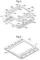
- FIG. 1 is an exploded isometric view of a fuel cell cassette in accordance with the invention;
- FIG. 2 is an isometric view of a fuel cell stack comprising three cassettes as shown in FIG. 1;
- FIG. 3 is a plan view of the fuel cell stack shown in FIG. 2
- FIG. 4 is a cross-sectional view taken along line 4-4 in FIG. 3;
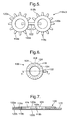
- FIG. 5 is a plan view of a separation ring, as stamped from sheet stock, in accordance with the invention;
- FIG. 6 is a plan view of the separation ring shown in FIG. 5, folded for use in a fuel cell cassette as shown in FIG. 1;
- FIG. 7 is a cross-sectional view taken along line 7-7 in FIG. 6;
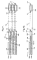
- FIG. 8 is an exploded cross-sectional view of a portion of a fuel cell stack as shown in FIG. 9;
- FIG. 9 is a cross-sectional view taken in
circle 9 in FIG. 4; - FIG. 10 is a cross-sectional view taken along line 10-10 in FIG. 3;
- FIG. 11 is a cross-sectional view taken in circle 10 in FIG. 4; and
- FIG. 12 is a cross-sectional view of a portion of a cassette taken through a cathode air exhaust opening.
- Referring to FIG. 1, a
fuel cell cassette 100 in accordance with the invention includes acassette housing 101 including a fuelcell mounting plate 102 and aseparation plate 104.Mounting plate 102 includes a large central electrode opening 106 for receiving afuel cell subassembly 128 as described below. Outboard ofcentral electrode opening 106 arecathode air inlets 108a,cathode air outlets 110a,fuel gas inlets 112a, andfuel gas outlets 114a.Separation plate 104 is provide with similar and mating air andfuel openings Separation plate 104 is formed as ashallow tray 115 such that a cavity is created between plates 102,104 for receiving fuel cell components and fuel gas as described below. Preferably, the mounting and separation plates are formed as by stamping or drawing from thin sheet stock (0.1 to 1.0 mm) of a ferritic stainless steel, although other materials such as austenitic stainless steel or high temperature alloys may also be acceptable. During assembly, plates 102,104 are joined to define a cassette housing (FIG. 12) by formation of ametallurgical bond 111 at their edges and around each of the air inlets and outlets (FIGS. 8-12) such that only openings 112,114 have access to the interior of the cassette. - Referring to FIGS. 1 and 3-7, a
spacer ring 126 is provided within the cassette for eachfuel gas inlet 112a,b and eachfuel gas outlet 114a,b. In a currently preferred embodiment for formingring 126, a pair ofrings 116a,b havingradial tabs 118 extending fromrings 120a,b are connected by alink 122.Radial tabs 118 are folded inward and line up with one another when the tworings link 122 to form solid columns of metal. The spaces between thetabs form openings 124 which allow fuel gas to flow from thefuel gas inlets 112 into the anode gas channel (space contained within the cassette), and into thefuel gas outlets 114 from the anode gas channel. The foldedrings 126 form solid metal spacers betweenmounting plate 102 andseparator plate 104, thus defining and maintaining a constant spacing therebetween despite assembly and operational loads on the cassette. Preferably,rings 126 are formed by stamping from sheet materials similar to those disclosed for forming the mounting plate and separator plate. - Referring to FIGS 1, 8, and 12, an anode-supported
fuel cell subassembly 128 is a three-layer structure comprising a structural anode, a ceramic electrolyte, and a cathode. The anode and cathode are also referred to herein generically as electrodes 129. Such a fuel cell subassembly is well known in the art of solid oxide fuel cells. To assembleassembly 128 to mountingplate 102, the cathode material is stripped or omitted (such as by screen printing) from the borders ofsubassembly 128, the exposed ceramic electrolyte surface of which is then thermally bonded to mountingplate 102 via adielectric seal 130 formed by brazing, a ceramic adhesive seal, or, preferably, glass. Thus,subassembly 128 is oriented such that thecathode surface 132 is exposed throughcentral opening 106 and theanode surface 134 faces inwardly of the cassette housing. Further, the cathode electrode ofsubassembly 128 is thus electrically insulated from mountingplate 102. - The ceramic
fuel cell subassembly 128 is preferably mounted to the mounting plate prior to cassette assembly although it can be done during the assembly process if desired. - Referring to FIGS. 8,11, and 12, the spaces adjacent to
cathode surface 132 andanode surface 134 serve two distinct functions: to allow passage of the appropriate reactive gases along the electrode surfaces, and to transmit electric current to and from the cell in known fashion. Each such space is filled with a conductive interconnect 136 that is porous or has passages formed into it to allow gas flow. Alternatively, an interconnect may have features formed into it, such as dimples or ribs, to make electrical contact. In a currently preferred embodiment, a metal mesh or foam interconnect 136 (cathode interconnect 136a andanode interconnect 136b) permits passage of gases along the electrodes and conducts current into and out of the cassette. Because of the corrosive nature of wet reformate on ferritic stainless steels at high temperatures, preferred materials for the interconnects are nickel mesh, a super-ferritic alloy such as Crofer 22 APU or a nickel-based superalloy such as Haynes 230 alloy. Note thatcathode interconnect 136a is separated by agap 138 from contact with mountingplate 102. - To complete the assembly of an
individual cassette 100, rings 126 are positioned over anode inlet andexhaust openings interconnect 136b is positioned onseparator plate 104, and mountingplate 102 bearingfuel cell element 128 is aligned with and placed overseparator plate 104. The two plates 102,104 are then metallurgically joined as by welding or brazing to formjoints 111 as described above. The edges of the "keyhole" shaped cathode inlet and exhaust openings 108,110 are formed similar to the perimeter of the cassette so that those edges are also laser welded together. This prevents cathode air from entering the anode gas channel (interior of the cassette), or anode gas leaking into the cathode air chimney/manifold. - Within the scope of the invention, the fuel cell subassembly may be oriented with either the cathode surface or the anode surface exposed through
opening 106 in mountingplate 102. However, the currently preferred assembly configuration has the anode fuel gas stream andfuel cell subassembly 128 contained within the cassette, as shown in FIGS. 10-12. With this approach, the metallurgical bond joint 111 at the perimeter edges of the cassette and the bond joint 130 between the fuel cell element and the mounting plate are the critical sealing joints for containing the combustible fuel gas within the cassette and stack, which can be leak tested at room temperature before final assembly of the fuel cell stack. This approach significantly improves the quality of the stack manufacturing process and reliability of the stack assembly. - Note that the anode and cathode inlet and exhaust openings in the cassette can be arranged around the fuel cell subassembly in any one of three distinct configurations, only one of which is shown. The most common prior art configuration results in cross flow between the fuel gas direction across the anode and the air direction across the cathode. This is accomplished by arranging the cathode inlet and exhaust openings on two opposite edges of a rectangular cassette, and the anode inlet and exhaust openings on opposing edges adjacent to the edges occupied by the cathode openings. The two other basic configurations are co-flow and counter-flow. In the co-flow configuration (FIG. 1), the anode and cathode flows are parallel and in the same direction. In the counter-flow case, the flows are parallel but in opposite directions. The currently preferred design is co-flow, which has been demonstrated by computer modeling to have the best temperature and current distribution across the fuel cell element.
- Referring to FIGS. 2-4 and 8-11, a
fuel cell stack 200 is formed by literally stacking together a plurality of individualfuel cell cassettes 100. The cassettes are bonded together outboard ofcentral opening 106 in a pattern surrounding the air and fuel gas inlets and exhausts using a fusible seal joint 202. The seal joint, preferably formed in place thermally, also serves as a dielectric isolator of the individual cassettes. One example of seal joint 202 is one formed using a glass-filled tape, which is fusible at high temperatures to provide a smooth, continuous, durable seal. Thus each cassette in the stack is at the potential of its anode, which is grounded to the separator plate and hence the mounting plate, plus whatever voltage is transferred from prior cassettes in the stack. The total voltage of the stack at any cassette is transferred to the next cassette via thecathode interconnect 136a which makes full contact with theouter surface 140 of the separator plate of the next cassette. The stack is terminated at opposite ends by conventional interconnect/terminals (not shown). Referring to FIGS. 10-12, it is seen that eachseparator plate 104 is drawn to two depths differing by adistance 142 so that when two cassettes are joined (mountingplate surface 204 of one cassette to theseparator plate surface 208 of another cassette), a cavity is formed between them which provides anopening 206 for air to enter thecathode interconnect 136a and spread acrosscathode surface 132. Thus, the cathode air channel is the space formed between the cassettes. The separator plate is formed so that there is aflat ridge 208 around the perimeter of the separator plate that is on the same plane as the anode opening seal areas. Bondedjoint seal 202 bonds/seals to this ridge and to the mountingplate surface 204 of the adjoining cassette. Therefore one cassette is sealed to the next cassette around the perimeter creating the cathode air channel and preventing cathode air from leaking out of the stack assembly. When the cassettes are stacked together, the cathode openings in the individual cassettes line up to form chimney-type manifolds for cathode air supply and return. - There are
metal spacers 210 placed between and within the two halves of each cassette at the anode manifold openings 212,214.Spacers 210 are formed with openings adjacent plate openings 112,114 so that anode gas can flow through them but they are otherwise substantially solid which prevents the cassette from collapsing at elevated temperatures and supports the anode opening seal between the cassettes. - There are also bonded joint seals in the flat area around the perimeter of each anode opening (supply and exhaust) between adjoining cassettes (anode opening seal areas). Preferably, such a seal does not require a compressive load for sealing and electrically insulating and is also a structural joint able to sustain compressive loads. These seals prevent anode gas in the anode gas chimney/manifolds (supply and return) from leaking into the cathode air channel (or vice-versa).
- In the preferred arrangement shown herein, the anode inlet and exhaust openings are round and are surrounded by a large flat surface, thereby reducing stress on the seal joint 202, and the large flat surfaces maximize the bond area. The result is a highly reliable and robust sealing joint for the passage of fuel gas from one cassette to the next.
- The preferred assembly has the cathode air contained in the sealed space between the cassettes. This seal is more difficult to accomplish than the seals for the anode openings, but it is not critical because any leaks would be only harmless cathode air. In addition, if any leaks should form in the anode opening seals or in the cell to mounting plate joint, the leaked fuel is contained within the cathode air stream and is thus contained within the stack assembly, resulting in a higher level of safety.
- While the invention has been described by reference to various specific embodiments, it should be understood that numerous changes may be made within the spirit and scope of the inventive concepts described. Accordingly, it is intended that the invention not be limited to the described embodiments, but will have full scope defined by the language of the following claims.
Claims (13)
- A modular fuel cell cassette for use in forming a fuel cell stack, comprising:a) a cassette housing having an electrode opening;b) a fuel cell subassembly comprising an electrode, said subassembly being mounted in said electrode opening such that one of a cathode surface and an anode surface of said electrode is exposed outside of said cassette and the other of said cathode surface and said anode surface of said electrode faces inwardly of said cassette housing;c) inlet and outlet openings for providing fuel gas to said anode surface and for removing fuel gas from said anode surface, respectively; andd) inlet and outlet openings for providing air to said cathode surface and for removing air from said cathode surface, respectively.
- A modular fuel cell cassette in accordance with Claim 1 further comprising:a) a first electrical interconnect extending between said inward-facing electrode surface and an inner surface of said housing; andb) a second electrical interconnect disposed in contact with said electrode exposed outside of said cassette and extending from said electrode opening.
- A modular fuel cell cassette in accordance with Claim 2 wherein said first and second electrical interconnects are formed of a material selected from the group consisting of metallic nickel and a nickel-based alloy.
- A modular fuel cell cassette in accordance with Claim 1 wherein said housing comprises a mounting plate and a separator plate joined along mutual edges thereof to enclose said captive space, and wherein said electrode opening is formed in said mounting plate.
- A modular fuel cell cassette in accordance with Claim 4 further comprising a plurality of spacers disposed within said housing outboard of said fuel cell subassembly for preventing collapse of said housing under load when assembled into said fuel cell stack.
- A modular fuel cell cassette in accordance with Claim 5 wherein said inward-facing electrode surface is said anode surface, and wherein said gas inlet opening includes a plurality of gas inlet openings formed in said mounting plate and in said separator plate in first portions of said plates between said cathode opening and mutual edges thereof, said spacers defining a first plurality of porous inlet rings disposed within said housing adjacent said plurality of fuel gas inlet openings.
- A modular fuel cell cassette in accordance with Claim 5 wherein said gas outlet opening includes a plurality of gas exhaust openings formed in said mounting plate and in said separator plate in second portions of said plates between said cathode opening and mutual edges thereof, said spacers defining a second plurality of porous rings disposed within said housing adjacent said plurality of fuel gas exhaust openings.
- A modular fuel cell cassette in accordance with Claim 5 wherein said exposed electrode surface is said cathode surface, and wherein said air inlet opening includes a plurality of air inlet openings formed in said mounting plate and in said separator plate in first portions of said plates between said cathode opening and mutual edges thereof, and wherein said air outlet opening includes a plurality of air exhaust openings formed in said mounting plate and in said separator plate in second portions of said plates between said cathode opening and mutual edges thereof, said mounting plate openings and said separator plate openings being joined along their mutual edges to prevent entry of air into said housing, said housing being shaped to form an air passage on an outer surface thereof between adjacent of said cassettes in said fuel cell stack.
- A modular fuel cell cassette in accordance with Claim 1 wherein the area of said exposed electrode surface is less than the area of said electrode opening.
- A fuel cell stack comprising a plurality of modular fuel cell cassettes wherein each of said cassettes includesa cassette housing having an electrode opening,a fuel cell subassembly comprising an electrode, said subassembly being mounted in said electrode opening such that one of a cathode surface and an anode surface of said electrode is exposed outside of said cassette and the other of said cathode surface and said anode surface of said electrode faces inwardly of said cassette housing,inlet and outlet openings for providing fuel gas to said anode surface and for removing fuel gas from said anode surface, respectively, andinlet and outlet openings for providing air to said cathode surface and for removing air from said cathode surface, respectively.
- A fuel cell stack in accordance with Claim 10 wherein each of said plurality of cassettes includes openings for passing fuel gas and air therethrough, and wherein said openings are aligned in said stack to form chimney manifolds for supplying and exhausting said fuel gas and said air to and from said plurality of cassettes.
- A fuel cell stack in accordance with Claim 10 wherein adjacent modular cassettes are joined and sealed together by a bonded seal joint.
- A fuel cell stack in accordance with Claim 12 wherein said bonded seal joint includes a glass.
Applications Claiming Priority (1)
| Application Number | Priority Date | Filing Date | Title |
|---|---|---|---|
| US11/027,095 US7306872B2 (en) | 2004-12-30 | 2004-12-30 | Modular fuel cell cassette for forming a solid-oxide fuel cell stack |
Publications (3)
| Publication Number | Publication Date |
|---|---|
| EP1677380A2 true EP1677380A2 (en) | 2006-07-05 |
| EP1677380A3 EP1677380A3 (en) | 2007-04-04 |
| EP1677380B1 EP1677380B1 (en) | 2011-03-16 |
Family
ID=36201442
Family Applications (1)
| Application Number | Title | Priority Date | Filing Date |
|---|---|---|---|
| EP05077880A Expired - Lifetime EP1677380B1 (en) | 2004-12-30 | 2005-12-14 | Modular fuel cell cassette for forming a solid-oxide fuel cell stack |
Country Status (4)
| Country | Link |
|---|---|
| US (1) | US7306872B2 (en) |
| EP (1) | EP1677380B1 (en) |
| AT (1) | ATE502412T1 (en) |
| DE (1) | DE602005026901D1 (en) |
Cited By (3)
| Publication number | Priority date | Publication date | Assignee | Title |
|---|---|---|---|---|
| EP2074671A4 (en) * | 2006-09-27 | 2010-11-03 | Delphi Tech Inc | Modular fuel cell cassette spacers for forming a solid-oxide fuel cell stack |
| WO2012152624A1 (en) * | 2011-05-09 | 2012-11-15 | Commissariat A L'energie Atomique Et Aux Energies Alternatives | Fuel cell comprising manifolds having individual injector seals |
| EP2390950A3 (en) * | 2010-05-27 | 2014-03-12 | Delphi Technologies, Inc. | Multiple stack fuel cell system |
Families Citing this family (7)
| Publication number | Priority date | Publication date | Assignee | Title |
|---|---|---|---|---|
| TWI273733B (en) * | 2005-11-08 | 2007-02-11 | Iner Ae | Solid oxide fuel cell stack of modularized design |
| US8293426B2 (en) | 2008-09-30 | 2012-10-23 | Battelle Memorial Institute | Cassettes for solid-oxide fuel cell stacks and methods of making the same |
| US8889303B2 (en) * | 2008-12-19 | 2014-11-18 | Battelle Memorial Institute | Cassette less SOFC stack and method of assembly |
| US9692079B2 (en) * | 2009-08-11 | 2017-06-27 | Delphi Technologies, Inc. | Laminated plate repeating fuel cell unit for an SOFC stack |
| US9112219B2 (en) | 2010-07-21 | 2015-08-18 | Delphi Technologies, Inc. | Multiple stack fuel cell system with shared plenum |
| US8197982B2 (en) * | 2011-11-15 | 2012-06-12 | Delphi Technologies, Inc. | Fuel cell with internal flow control |
| US9812717B2 (en) | 2013-09-20 | 2017-11-07 | Delphi Technologies, Inc. | Fuel cell cassette with compliant seal |
Family Cites Families (7)
| Publication number | Priority date | Publication date | Assignee | Title |
|---|---|---|---|---|
| DE1187243B (en) | 1962-04-09 | 1965-02-18 | Du Pont | Process for the preparation of halogen-substituted aromatic amines |
| DE10044703B4 (en) | 2000-09-09 | 2013-10-17 | Elringklinger Ag | Fuel cell unit, fuel cell block assembly and method for producing a fuel cell block assembly |
| US6770395B2 (en) | 2000-10-23 | 2004-08-03 | Materials And Systems Research, Inc. | Internally manifolded, planar solid oxide fuel cell (SOFC) stack with an inexpensive interconnect |
| US6824910B2 (en) | 2001-01-24 | 2004-11-30 | The Regents Of The University Of California | Co-flow planar SOFC fuel cell stack |
| US6805990B2 (en) | 2001-10-24 | 2004-10-19 | Fuelcell Energy, Ltd. | Flat plate fuel cell stack |
| US7270906B2 (en) | 2002-06-24 | 2007-09-18 | Delphi Technologies, Inc. | Solid-oxide fuel cell module for a fuel cell stack |
| US20040265666A1 (en) | 2003-06-27 | 2004-12-30 | Weil K. Scott | Solid oxide fuel cell frames and method of manufacture |
-
2004
- 2004-12-30 US US11/027,095 patent/US7306872B2/en not_active Expired - Lifetime
-
2005
- 2005-12-14 EP EP05077880A patent/EP1677380B1/en not_active Expired - Lifetime
- 2005-12-14 AT AT05077880T patent/ATE502412T1/en not_active IP Right Cessation
- 2005-12-14 DE DE602005026901T patent/DE602005026901D1/en not_active Expired - Lifetime
Cited By (7)
| Publication number | Priority date | Publication date | Assignee | Title |
|---|---|---|---|---|
| EP2074671A4 (en) * | 2006-09-27 | 2010-11-03 | Delphi Tech Inc | Modular fuel cell cassette spacers for forming a solid-oxide fuel cell stack |
| EP2390950A3 (en) * | 2010-05-27 | 2014-03-12 | Delphi Technologies, Inc. | Multiple stack fuel cell system |
| US9356307B2 (en) | 2010-05-27 | 2016-05-31 | Delphi Technologies, Inc. | Multiple stack fuel cell system |
| WO2012152624A1 (en) * | 2011-05-09 | 2012-11-15 | Commissariat A L'energie Atomique Et Aux Energies Alternatives | Fuel cell comprising manifolds having individual injector seals |
| FR2975228A1 (en) * | 2011-05-09 | 2012-11-16 | Commissariat Energie Atomique | FUEL CELL WITH INDIVIDUAL INJECTOR JOINTS |
| CN103636043A (en) * | 2011-05-09 | 2014-03-12 | 原子能和辅助替代能源委员会 | Fuel cell comprising manifolds having individual injector seals |
| US9099697B2 (en) | 2011-05-09 | 2015-08-04 | Commissariat A L'energie Atomique Et Aux Energies Alternatives | Fuel cell comprising manifolds having individual injector seals |
Also Published As
| Publication number | Publication date |
|---|---|
| US20060147786A1 (en) | 2006-07-06 |
| US7306872B2 (en) | 2007-12-11 |
| EP1677380B1 (en) | 2011-03-16 |
| EP1677380A3 (en) | 2007-04-04 |
| ATE502412T1 (en) | 2011-04-15 |
| DE602005026901D1 (en) | 2011-04-28 |
Similar Documents
| Publication | Publication Date | Title |
|---|---|---|
| US7270906B2 (en) | Solid-oxide fuel cell module for a fuel cell stack | |
| EP0750798B1 (en) | Solid oxide fuel cell stacking assembly | |
| RU2231172C2 (en) | Pile of fuel elements with membrane of polymer electrolyte | |
| US6833210B2 (en) | Fuel cell | |
| US5362578A (en) | Integrated main rail, feed rail, and current collector | |
| KR101388318B1 (en) | Solid oxide fuel cell | |
| EP1677377B1 (en) | Ceramic coatings for insulating modular fuel cell cassettes in a solid-oxide fuel cell stack | |
| US6649296B1 (en) | Unitized cell solid oxide fuel cells | |
| US7306872B2 (en) | Modular fuel cell cassette for forming a solid-oxide fuel cell stack | |
| US20050249996A1 (en) | Fuel cell assemblies using metallic bipolar separators | |
| JP4121315B2 (en) | Fuel cell | |
| US6866956B2 (en) | Fuel cell | |
| US8168347B2 (en) | SOFC assembly joint spacing | |
| US6811909B2 (en) | Fuel cell | |
| US7601450B2 (en) | Hybrid interconnect for a solid-oxide fuel cell stack | |
| US6500578B1 (en) | Stacking and manifolding of angularly offset, unitized solid oxide fuel cells | |
| US7758989B2 (en) | Modular fuel cell cassette spacers for forming a solid-oxide fuel cell stack | |
| JP2008103216A (en) | Fuel cell | |
| EP2681790B1 (en) | Fuel cell stack | |
| US20240047722A1 (en) | Gas diffusion method for use with fuel cell stack | |
| KR20260032871A (en) | Interconnect including cell nest and method of assembling an electrochemical cell stack including the interconnect | |
| WO2025082582A1 (en) | Method of assembly of an electrochemical cell unit and electrochemical cell unit |
Legal Events
| Date | Code | Title | Description |
|---|---|---|---|
| PUAI | Public reference made under article 153(3) epc to a published international application that has entered the european phase |
Free format text: ORIGINAL CODE: 0009012 |
|
| AK | Designated contracting states |
Kind code of ref document: A2 Designated state(s): AT BE BG CH CY CZ DE DK EE ES FI FR GB GR HU IE IS IT LI LT LU LV MC NL PL PT RO SE SI SK TR |
|
| AX | Request for extension of the european patent |
Extension state: AL BA HR MK YU |
|
| RIN1 | Information on inventor provided before grant (corrected) |
Inventor name: HALTINER, JR., KARL J. Inventor name: WEIL, KENNETH S. Inventor name: SPRENKLE., VINCENT L. Inventor name: MUKERJEE, SUBHASISH 157 Inventor name: DEIBLER, JOHN E. Inventor name: PAXTON, DEAN Inventor name: MEINHARDT, KERRY D. Inventor name: CHICK, LAWRENCE A. |
|
| PUAL | Search report despatched |
Free format text: ORIGINAL CODE: 0009013 |
|
| AK | Designated contracting states |
Kind code of ref document: A3 Designated state(s): AT BE BG CH CY CZ DE DK EE ES FI FR GB GR HU IE IS IT LI LT LU LV MC NL PL PT RO SE SI SK TR |
|
| AX | Request for extension of the european patent |
Extension state: AL BA HR MK YU |
|
| 17P | Request for examination filed |
Effective date: 20071004 |
|
| AKX | Designation fees paid |
Designated state(s): AT BE BG CH CY CZ DE DK EE ES FI FR GB GR HU IE IS IT LI LT LU LV MC NL PL PT RO SE SI SK TR |
|
| 17Q | First examination report despatched |
Effective date: 20071123 |
|
| GRAP | Despatch of communication of intention to grant a patent |
Free format text: ORIGINAL CODE: EPIDOSNIGR1 |
|
| GRAS | Grant fee paid |
Free format text: ORIGINAL CODE: EPIDOSNIGR3 |
|
| GRAA | (expected) grant |
Free format text: ORIGINAL CODE: 0009210 |
|
| AK | Designated contracting states |
Kind code of ref document: B1 Designated state(s): AT BE BG CH CY CZ DE DK EE ES FI FR GB GR HU IE IS IT LI LT LU LV MC NL PL PT RO SE SI SK TR |
|
| REG | Reference to a national code |
Ref country code: GB Ref legal event code: FG4D |
|
| REG | Reference to a national code |
Ref country code: CH Ref legal event code: EP |
|
| REG | Reference to a national code |
Ref country code: IE Ref legal event code: FG4D |
|
| REF | Corresponds to: |
Ref document number: 602005026901 Country of ref document: DE Date of ref document: 20110428 Kind code of ref document: P |
|
| REG | Reference to a national code |
Ref country code: DE Ref legal event code: R096 Ref document number: 602005026901 Country of ref document: DE Effective date: 20110428 |
|
| REG | Reference to a national code |
Ref country code: NL Ref legal event code: VDEP Effective date: 20110316 |
|
| PG25 | Lapsed in a contracting state [announced via postgrant information from national office to epo] |
Ref country code: ES Free format text: LAPSE BECAUSE OF FAILURE TO SUBMIT A TRANSLATION OF THE DESCRIPTION OR TO PAY THE FEE WITHIN THE PRESCRIBED TIME-LIMIT Effective date: 20110627 Ref country code: GR Free format text: LAPSE BECAUSE OF FAILURE TO SUBMIT A TRANSLATION OF THE DESCRIPTION OR TO PAY THE FEE WITHIN THE PRESCRIBED TIME-LIMIT Effective date: 20110617 Ref country code: LV Free format text: LAPSE BECAUSE OF FAILURE TO SUBMIT A TRANSLATION OF THE DESCRIPTION OR TO PAY THE FEE WITHIN THE PRESCRIBED TIME-LIMIT Effective date: 20110316 Ref country code: SE Free format text: LAPSE BECAUSE OF FAILURE TO SUBMIT A TRANSLATION OF THE DESCRIPTION OR TO PAY THE FEE WITHIN THE PRESCRIBED TIME-LIMIT Effective date: 20110316 Ref country code: LT Free format text: LAPSE BECAUSE OF FAILURE TO SUBMIT A TRANSLATION OF THE DESCRIPTION OR TO PAY THE FEE WITHIN THE PRESCRIBED TIME-LIMIT Effective date: 20110316 |
|
| LTIE | Lt: invalidation of european patent or patent extension |
Effective date: 20110316 |
|
| PG25 | Lapsed in a contracting state [announced via postgrant information from national office to epo] |
Ref country code: SI Free format text: LAPSE BECAUSE OF FAILURE TO SUBMIT A TRANSLATION OF THE DESCRIPTION OR TO PAY THE FEE WITHIN THE PRESCRIBED TIME-LIMIT Effective date: 20110316 Ref country code: BG Free format text: LAPSE BECAUSE OF FAILURE TO SUBMIT A TRANSLATION OF THE DESCRIPTION OR TO PAY THE FEE WITHIN THE PRESCRIBED TIME-LIMIT Effective date: 20110616 Ref country code: FI Free format text: LAPSE BECAUSE OF FAILURE TO SUBMIT A TRANSLATION OF THE DESCRIPTION OR TO PAY THE FEE WITHIN THE PRESCRIBED TIME-LIMIT Effective date: 20110316 Ref country code: AT Free format text: LAPSE BECAUSE OF FAILURE TO SUBMIT A TRANSLATION OF THE DESCRIPTION OR TO PAY THE FEE WITHIN THE PRESCRIBED TIME-LIMIT Effective date: 20110316 Ref country code: CY Free format text: LAPSE BECAUSE OF FAILURE TO SUBMIT A TRANSLATION OF THE DESCRIPTION OR TO PAY THE FEE WITHIN THE PRESCRIBED TIME-LIMIT Effective date: 20110316 |
|
| PG25 | Lapsed in a contracting state [announced via postgrant information from national office to epo] |
Ref country code: BE Free format text: LAPSE BECAUSE OF FAILURE TO SUBMIT A TRANSLATION OF THE DESCRIPTION OR TO PAY THE FEE WITHIN THE PRESCRIBED TIME-LIMIT Effective date: 20110316 |
|
| PG25 | Lapsed in a contracting state [announced via postgrant information from national office to epo] |
Ref country code: EE Free format text: LAPSE BECAUSE OF FAILURE TO SUBMIT A TRANSLATION OF THE DESCRIPTION OR TO PAY THE FEE WITHIN THE PRESCRIBED TIME-LIMIT Effective date: 20110316 Ref country code: PT Free format text: LAPSE BECAUSE OF FAILURE TO SUBMIT A TRANSLATION OF THE DESCRIPTION OR TO PAY THE FEE WITHIN THE PRESCRIBED TIME-LIMIT Effective date: 20110718 |
|
| PG25 | Lapsed in a contracting state [announced via postgrant information from national office to epo] |
Ref country code: SK Free format text: LAPSE BECAUSE OF FAILURE TO SUBMIT A TRANSLATION OF THE DESCRIPTION OR TO PAY THE FEE WITHIN THE PRESCRIBED TIME-LIMIT Effective date: 20110316 Ref country code: RO Free format text: LAPSE BECAUSE OF FAILURE TO SUBMIT A TRANSLATION OF THE DESCRIPTION OR TO PAY THE FEE WITHIN THE PRESCRIBED TIME-LIMIT Effective date: 20110316 Ref country code: CZ Free format text: LAPSE BECAUSE OF FAILURE TO SUBMIT A TRANSLATION OF THE DESCRIPTION OR TO PAY THE FEE WITHIN THE PRESCRIBED TIME-LIMIT Effective date: 20110316 Ref country code: IS Free format text: LAPSE BECAUSE OF FAILURE TO SUBMIT A TRANSLATION OF THE DESCRIPTION OR TO PAY THE FEE WITHIN THE PRESCRIBED TIME-LIMIT Effective date: 20110716 |
|
| PG25 | Lapsed in a contracting state [announced via postgrant information from national office to epo] |
Ref country code: NL Free format text: LAPSE BECAUSE OF FAILURE TO SUBMIT A TRANSLATION OF THE DESCRIPTION OR TO PAY THE FEE WITHIN THE PRESCRIBED TIME-LIMIT Effective date: 20110316 |
|
| PLBE | No opposition filed within time limit |
Free format text: ORIGINAL CODE: 0009261 |
|
| STAA | Information on the status of an ep patent application or granted ep patent |
Free format text: STATUS: NO OPPOSITION FILED WITHIN TIME LIMIT |
|
| 26N | No opposition filed |
Effective date: 20111219 |
|
| PG25 | Lapsed in a contracting state [announced via postgrant information from national office to epo] |
Ref country code: PL Free format text: LAPSE BECAUSE OF FAILURE TO SUBMIT A TRANSLATION OF THE DESCRIPTION OR TO PAY THE FEE WITHIN THE PRESCRIBED TIME-LIMIT Effective date: 20110316 Ref country code: DK Free format text: LAPSE BECAUSE OF FAILURE TO SUBMIT A TRANSLATION OF THE DESCRIPTION OR TO PAY THE FEE WITHIN THE PRESCRIBED TIME-LIMIT Effective date: 20110316 |
|
| REG | Reference to a national code |
Ref country code: DE Ref legal event code: R097 Ref document number: 602005026901 Country of ref document: DE Effective date: 20111219 |
|
| PG25 | Lapsed in a contracting state [announced via postgrant information from national office to epo] |
Ref country code: IT Free format text: LAPSE BECAUSE OF FAILURE TO SUBMIT A TRANSLATION OF THE DESCRIPTION OR TO PAY THE FEE WITHIN THE PRESCRIBED TIME-LIMIT Effective date: 20110316 |
|
| PG25 | Lapsed in a contracting state [announced via postgrant information from national office to epo] |
Ref country code: MC Free format text: LAPSE BECAUSE OF NON-PAYMENT OF DUE FEES Effective date: 20111231 |
|
| REG | Reference to a national code |
Ref country code: CH Ref legal event code: PL |
|
| REG | Reference to a national code |
Ref country code: IE Ref legal event code: MM4A |
|
| PG25 | Lapsed in a contracting state [announced via postgrant information from national office to epo] |
Ref country code: IE Free format text: LAPSE BECAUSE OF NON-PAYMENT OF DUE FEES Effective date: 20111214 Ref country code: LI Free format text: LAPSE BECAUSE OF NON-PAYMENT OF DUE FEES Effective date: 20111231 Ref country code: CH Free format text: LAPSE BECAUSE OF NON-PAYMENT OF DUE FEES Effective date: 20111231 |
|
| PG25 | Lapsed in a contracting state [announced via postgrant information from national office to epo] |
Ref country code: LU Free format text: LAPSE BECAUSE OF NON-PAYMENT OF DUE FEES Effective date: 20111214 |
|
| PG25 | Lapsed in a contracting state [announced via postgrant information from national office to epo] |
Ref country code: TR Free format text: LAPSE BECAUSE OF FAILURE TO SUBMIT A TRANSLATION OF THE DESCRIPTION OR TO PAY THE FEE WITHIN THE PRESCRIBED TIME-LIMIT Effective date: 20110316 |
|
| PG25 | Lapsed in a contracting state [announced via postgrant information from national office to epo] |
Ref country code: HU Free format text: LAPSE BECAUSE OF FAILURE TO SUBMIT A TRANSLATION OF THE DESCRIPTION OR TO PAY THE FEE WITHIN THE PRESCRIBED TIME-LIMIT Effective date: 20110316 |
|
| PGFP | Annual fee paid to national office [announced via postgrant information from national office to epo] |
Ref country code: GB Payment date: 20131227 Year of fee payment: 9 |
|
| PGFP | Annual fee paid to national office [announced via postgrant information from national office to epo] |
Ref country code: FR Payment date: 20131217 Year of fee payment: 9 |
|
| GBPC | Gb: european patent ceased through non-payment of renewal fee |
Effective date: 20141214 |
|
| REG | Reference to a national code |
Ref country code: FR Ref legal event code: ST Effective date: 20150831 |
|
| PG25 | Lapsed in a contracting state [announced via postgrant information from national office to epo] |
Ref country code: GB Free format text: LAPSE BECAUSE OF NON-PAYMENT OF DUE FEES Effective date: 20141214 |
|
| PG25 | Lapsed in a contracting state [announced via postgrant information from national office to epo] |
Ref country code: FR Free format text: LAPSE BECAUSE OF NON-PAYMENT OF DUE FEES Effective date: 20141231 |
|
| PGFP | Annual fee paid to national office [announced via postgrant information from national office to epo] |
Ref country code: DE Payment date: 20161229 Year of fee payment: 12 |
|
| REG | Reference to a national code |
Ref country code: DE Ref legal event code: R119 Ref document number: 602005026901 Country of ref document: DE |
|
| PG25 | Lapsed in a contracting state [announced via postgrant information from national office to epo] |
Ref country code: DE Free format text: LAPSE BECAUSE OF NON-PAYMENT OF DUE FEES Effective date: 20180703 |