EP1677340A2 - Ceramic discharge vessel with expanded reaction-bonded aluminium oxide member - Google Patents
Ceramic discharge vessel with expanded reaction-bonded aluminium oxide member Download PDFInfo
- Publication number
- EP1677340A2 EP1677340A2 EP05026731A EP05026731A EP1677340A2 EP 1677340 A2 EP1677340 A2 EP 1677340A2 EP 05026731 A EP05026731 A EP 05026731A EP 05026731 A EP05026731 A EP 05026731A EP 1677340 A2 EP1677340 A2 EP 1677340A2
- Authority
- EP
- European Patent Office
- Prior art keywords
- discharge vessel
- ceramic
- reaction
- aluminum oxide
- ceramic body
- Prior art date
- Legal status (The legal status is an assumption and is not a legal conclusion. Google has not performed a legal analysis and makes no representation as to the accuracy of the status listed.)
- Withdrawn
Links
Images



Classifications
-
- H—ELECTRICITY
- H01—ELECTRIC ELEMENTS
- H01J—ELECTRIC DISCHARGE TUBES OR DISCHARGE LAMPS
- H01J61/00—Gas-discharge or vapour-discharge lamps
- H01J61/02—Details
- H01J61/30—Vessels; Containers
-
- H—ELECTRICITY
- H01—ELECTRIC ELEMENTS
- H01J—ELECTRIC DISCHARGE TUBES OR DISCHARGE LAMPS
- H01J61/00—Gas-discharge or vapour-discharge lamps
- H01J61/02—Details
- H01J61/30—Vessels; Containers
- H01J61/302—Vessels; Containers characterised by the material of the vessel
-
- H—ELECTRICITY
- H01—ELECTRIC ELEMENTS
- H01J—ELECTRIC DISCHARGE TUBES OR DISCHARGE LAMPS
- H01J61/00—Gas-discharge or vapour-discharge lamps
- H01J61/02—Details
- H01J61/36—Seals between parts of vessels; Seals for leading-in conductors; Leading-in conductors
-
- H—ELECTRICITY
- H01—ELECTRIC ELEMENTS
- H01J—ELECTRIC DISCHARGE TUBES OR DISCHARGE LAMPS
- H01J9/00—Apparatus or processes specially adapted for the manufacture, installation, removal, maintenance of electric discharge tubes, discharge lamps, or parts thereof; Recovery of material from discharge tubes or lamps
- H01J9/24—Manufacture or joining of vessels, leading-in conductors or bases
- H01J9/26—Sealing together parts of vessels
- H01J9/265—Sealing together parts of vessels specially adapted for gas-discharge tubes or lamps
- H01J9/266—Sealing together parts of vessels specially adapted for gas-discharge tubes or lamps specially adapted for gas-discharge lamps
Definitions
- This invention relates to ceramic discharge vessels and in particular to discharge vessels for high-intensity discharge applications that include a sapphire tube body.
- Ceramic discharge vessels are generally used for high-intensity discharge (HID) lamps such as high-pressure sodium (HPS), high-pressure mercury, and metal halide lamps.
- these discharge vessels are formed from multiple ceramic components that are co-sintered to form hermetic seals between the parts without the use of a frit material. This technique relies on a differential shrinkage of the ceramic components to create an interference fit between the parts.
- the preferred ceramic for HID lamp applications is polycrystalline alumina (PCA), although other ceramics such as sapphire, yttrium aluminum garnet, aluminum nitride and aluminum oxynitride may also be used.
- Sapphire is an excellent transparent ceramic material, except that it is limited to straight shapes defined by crystal growth techniques.
- Single-crystal sapphire tubes typically grown by the EFG (edge-defined, film-feed growth) method are useful for ceramic metal halide lamps.
- EFG edge-defined, film-feed growth
- PCA to PCA seals rely on the differential shrinkage of the PCA parts, this technique is normally not applicable to sapphire to PCA seals because the sapphire tube does not shrink during the sintering of PCA parts.
- some recent designs of ceramic discharge vessels for low wattage, automotive applications use polycrystalline alumina hats that fit over the ends of the sapphire tube. See, e.g., International Patent Application No. WO 99/41 761.
- the PCA hat shrinks around the end of sapphire tube during sintering to create a seal with the exterior surface of the tube.
- the high thermal mass of the PCA hat causes high heat losses via radiation from the hat's surface and induces a severe thermal stress that can lead to a high incidence of cracking.
- Reaction-bonded aluminum oxide is a relatively new class of ceramic material with low ( ⁇ 1%) dimensional shrinkage.
- RBAO is new relative to conventional sintering of alumina in that both reactions and sintering take place in the compacted body simultaneously during heating.
- the method of producing strong RBAO bodies starts with compacts of milled mixtures of aluminum metal and aluminum oxide powders that are heat treated at about 1200 to about 1550°C. Typically, it is desired that the expansion due to the Al metal to Al 2 O 3 reaction and the shrinkage on sintering of the Al 2 O 3 be nearly balanced.
- the present invention involves coaxing the RBAO into a range where densification is accompanied by a small expansion during heating.
- the expansion of the RBAO component is used to create the hermetic seal between ceramic components.
- the RBAO part swells and seals against a constricting surface. This is can be thought of as the opposite of the differential shrinkage method used for PCA.
- the RBAO expands during sintering, it is possible to use an inserted RBAO plug in a sapphire tube to seal the ends of the tube and thereby eliminate the use of an external PCA hat.
- This construction should result in a better thermal profile, less stresses, and higher survivability.
- an internally-sealed plug construction is preferred, the use of expanded RBAO is not limited to forming internal seals within the arc tube.
- the use of expanded RBAO for creating hermetic seals allows more flexibility in the manufacturing of ceramic discharge vessels.
- a ceramic discharge vessel comprising a ceramic body and at least one expanded reaction-bonded aluminum oxide member hermetically sealed to the ceramic body.
- a method of forming a hermetic seal in a ceramic discharge vessel comprising: (a) forming a ceramic body; (b) forming a reaction-bonded aluminum oxide member in a green state by compacting a mixture of aluminum metal and aluminum oxide powders; (c) assembling the ceramic body and the reaction-bonded aluminum oxide member in the green state to form an assembly; and (d) reaction sintering the assembly to cause the reaction-bonded aluminum oxide member to expand and form a hermetic seal with the ceramic body.
- Fig. 1 is a cross-sectional illustration of a ceramic discharge vessel for an electrodeless lamp in accordance with this invention.
- Fig. 2 is an illustration of an annular sealing member in accordance with this invention.
- Fig. 3 is a cross-sectional illustration of a 5-piece ceramic discharge vessel according to this invention that incorporates the annular sealing member of Fig. 2.
- Fig. 4 is a cross-sectional illustration of a 3-piece ceramic discharge vessel according to this invention wherein the sealing member has an integral capillary tube.
- Fig. 5 is a cross-sectional illustration of an alternate embodiment of the ceramic discharge vessel shown in Fig. 1.
- Fig. 6 is a cross-sectional illustration of a ceramic discharge vessel for an HPS lighting application in accordance with this invention.
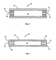
- Fig. 7 is a cross-sectional illustration of an alternate embodiment of the ceramic discharge vessel shown in Fig. 6.
- Fig. 8 is a cross-sectional illustration of a ceramic discharge vessel according to this invention that has expanded RBAO capillary tubes.
- Equation (1) The general equation for the total dimensional change, S, after a complete reaction-bonding cycle for an RBAO ceramic is given by Equation (1) below:
- Equation (1) indicates that a higher volume fraction of Al and a high green density can yield a final expansion (rather than shrinkage) during sintering of the Al/Al 2 O 3 compacts.
- a volume expansion of about 1-4% occurs at ⁇ 700°C because of the melting of the Al phase.
- Fig. 1 is a cross-sectional illustration of a ceramic discharge vessel for an electrodeless lamp in accordance with this invention.
- the discharge vessel 2 has a tubular body 3 and sealing members 7 which together define a discharge chamber 12.
- the tubular body 3 is comprised of a ceramic material, preferably translucent PCA or sapphire.
- Sealing members 7 are comprised of expanded RBAO plugs.
- An alternate embodiment of this discharge vessel is shown in Fig. 5.
- recesses 43 have been made in the ends of tubular body 3' of discharge vessel 2' in order to receive sealing members 7.
- the edges 45 of the recess 43 limit the insertion depth of the sealing members 7 thereby providing for more accurate positioning.
- the sealing members 7 in their green state would be inserted into the ends of a PCA or sapphire tube and expanded by reaction sintering. As the diameter of the RBAO plugs expands during reaction sintering, an interference fit is created with the constricting inner surface 5 of the tubular body 3 and a hermetic seal is formed between the tubular body 3 and the sealing members 7.
- the PCA tube may be fully sintered to prior to combining it with the RBAO plug in which case only minimal shrinkage of the PCA tube may occur during the reaction sintering of the RBAO parts, or the PCA tube may be only prefired in which case the PCA tube will shrink as the RBAO parts are expanded during the reaction sintering step.
- the alumina tube is prefired at 850°C to 1350°C before being combined with the green RBAO part.
- the assembled parts are then reaction sintered at a temperature less than 1350°C to at least partially bond the parts and then sintered at a higher temperature to about 1 850°C in hydrogen, an N 2 -H 2 mixture, or vacuum, to increase transmittance and finish the seal.
- a sinter-HIP (hot isostatic pressing) process which sinters the assembly to a closed-pore stage followed by HIP may also be used to bring about high transmittance.
- Fig. 3 is a cross-sectional illustration of a 5-piece ceramic discharge vessel.
- the discharge vessel 21 has tubular body 3 and is sealed with annular sealing members 20 (shown separately in Fig. 2).
- the annular sealing members 20 have an aperture 23 for receiving capillary tube 25.
- Capillary tube 25 has a bore 29 suitable for receiving an electrode assembly (not shown).
- capillary tube 25 is comprised of PCA that has been at least prefired, and, more preferably, fully sintered, before being inserted into the green RBAO sealing member.
- annular sealing members 20' and the capillary tubes 25' are made as an integral piece composed of expanded RBAO.
- a metal halide fill material may be inserted into the discharge chamber 12 after the hermetic seals have been formed between the ceramic parts.
- a typical metal halide fill material comprises mercury plus a mixture of metal halide salts, e.g., Nal, Cal 2 , Dyl 3 , Hol 3 , Tml 3 , and TII.
- the discharge chamber 12 will also contain a buffer gas, e.g., 30 to 300 torr Xe or Ar. Higher fill gas pressures may also be used, e.g., 1-30 bar Xe at 20°C. Such higher pressures are useful for lamps where instant starting is required, e.g., automotive lamps.
- Electrode assemblies are inserted into each capillary tube 25 such that one end protrudes out of the discharge vessel to provide an electrical connection.
- the tips of the electrode assemblies that extend into the discharge chamber are fitted with a tungsten coil or other similar means for providing a point of attachment for the arc discharge.
- the electrode assemblies are sealed hermetically to the capillary tubes by a frit material (preferably, a Al 2 O 3 -SiO 2- Dy 2 O 3 frit).
- Figs. 6 and 7 are cross-sectional illustrations of two alternate embodiments of ceramic discharge vessels for HPS lamps in accordance with this invention.
- the discharge vessel 50 has a tubular body 53 comprised of PCA.
- Annular plugs 57 comprised of expanded RBAO are sealed in each end of the tubular body 53 thereby defining discharge chamber 51.
- the aperture 59 in annular plugs 57 is for receiving an electrode assembly which typically consists of a niobium feedthrough to which a tungsten electrode is attached.
- the niobium feedthrough is frit sealed in the aperture after a sodium/mercury amalgam and a buffer gas has been added to discharge chamber 51.
- the annular plugs 57' of discharge vessel 50' have a flange 60 that seats against the end of the tube to provide for more accurate positioning of the annular plug 57'.
- Fig. 8 is a further embodiment of this invention wherein the ceramic discharge vessel 70 has a tubular body 73 and capillary tubes 77.
- the tubular body 73 may be comprised of sapphire or PCA and the capillary tubes 77 are comprised of expanded RBAO.
- the capillary tubes 77 are inserted to a predetermined depth thereby defining discharge chamber 82 and are expanded during the reaction sintering of the RBAO to form a hermetic seal with the inner surface 75 of the tubular body 73.
- the capillary tubes 77 have a bore 79 for receiving an electrode assembly and discharge chamber 82 may be filled with the metal halide fill described previously.
- solid RBAO plugs were made and sealed into the ends of sintered PCA tubes.
- aluminum metal powder having an average 20 ⁇ m particle size Johnson-Matthey
- alumina powder CR6 or CR1 from Baikowski
- CR6 alumina powder which has a surface area of 6 m 2 /g was preferred because of its sinterability.
- Finer aluminum powders are available, but submicron aluminum powders would require special precautions as spontaneous combustion could occur. For aluminum powders greater than 1 ⁇ m, handling in air at ambient temperature is acceptable.
- Aluminum metal volume content may be in a range from 10 to 70 volume percent, and preferably from 50 to 60 vol%. When the aluminum metal content is high (>60 vol%), the pressed parts tend to be soft and frail making handling more difficult.
- the Al/Al 2 O 3 mixtures were ball-milled for 2 hours in methanol using 5mm ZrO 2 balls and high-density polyethylene bottles. Methanol was used for ball milling since aluminum metal powder reacts with water. Ball milling was limited to 2 hours to prevent excessive pick up of ZrO 2 from the media. After pan drying, the powder was broken up using mortar/pestle. The powders were uniaxially pressed or isopressed at 35ksi or higher.
- the Al/Al 2 O 3 compacts could achieve a high green density of 60-80% of theoretical density. If needed, the green plugs could be machined to a predetermined size.
- the green RBAO plugs were 4.90mm in diameter by 2mm thick, and the PCA outer tubes had a 4.95mm ID.
- the entire samples were reaction-sintered under flowing air or oxygen using the following temperature cycle: (1) heating at 1 °C/min to 700°C with a hold at 700°C for 24h; (2) continue heating at 1 °C/min to 1100°C with a hold at 1100°C for 24h; (3) continue heating at 1 °C/min to 1 550°C with a hold at 1 550°C for 24h; and finally cooling at 30°C/min to room temperature.
- the final hold temperature could be higher than 1550°C, e.g., 1600-1900°C, in order to promote full densification. This depends on the starting green density and particles sizes of the Al and Al 2 O 3 phases.
- a pure oxygen atmosphere is preferred, because it results in a faster oxidation of the Al metal particles to Al 2 O 3 .
- a temperature of 1550°C was sufficient to form hermetic body and direct bonds of the expanded RBAO plugs to the outer alumina tubes.
- the RBAO plugs had a final expansion of 0.35mm as the diameter increased from 4.90mm to 5.25mm resulting in a net interference of about 6%.
- Longitudinal cracks in the outer PCA tubes appeared after the reaction sintering cycle when high temperature ramp rates (5°C/min) were used.
- the length of the bond between the expanded RBAO plug and outer alumina tube was 2mm.
- Successfully bonded tubes were leak tight to ⁇ 10-9 scc/sec.
Landscapes
- Engineering & Computer Science (AREA)
- Manufacturing & Machinery (AREA)
- Vessels And Coating Films For Discharge Lamps (AREA)
- Manufacture Of Electron Tubes, Discharge Lamp Vessels, Lead-In Wires, And The Like (AREA)
- Ceramic Products (AREA)
- Chemical Vapour Deposition (AREA)
Abstract
Description
- This invention relates to ceramic discharge vessels and in particular to discharge vessels for high-intensity discharge applications that include a sapphire tube body.
- Ceramic discharge vessels are generally used for high-intensity discharge (HID) lamps such as high-pressure sodium (HPS), high-pressure mercury, and metal halide lamps. Typically, these discharge vessels are formed from multiple ceramic components that are co-sintered to form hermetic seals between the parts without the use of a frit material. This technique relies on a differential shrinkage of the ceramic components to create an interference fit between the parts. The preferred ceramic for HID lamp applications is polycrystalline alumina (PCA), although other ceramics such as sapphire, yttrium aluminum garnet, aluminum nitride and aluminum oxynitride may also be used.
- Sapphire is an excellent transparent ceramic material, except that it is limited to straight shapes defined by crystal growth techniques. Single-crystal sapphire tubes typically grown by the EFG (edge-defined, film-feed growth) method are useful for ceramic metal halide lamps. However, while PCA to PCA seals rely on the differential shrinkage of the PCA parts, this technique is normally not applicable to sapphire to PCA seals because the sapphire tube does not shrink during the sintering of PCA parts. As a solution, some recent designs of ceramic discharge vessels for low wattage, automotive applications use polycrystalline alumina hats that fit over the ends of the sapphire tube. See, e.g., International Patent Application No. WO 99/41 761. The PCA hat shrinks around the end of sapphire tube during sintering to create a seal with the exterior surface of the tube. However, the high thermal mass of the PCA hat causes high heat losses via radiation from the hat's surface and induces a severe thermal stress that can lead to a high incidence of cracking.
- In addition, the cost of this sapphire-PCA construction is relatively high compared to competing technologies. Unfortunately, sapphire tubes with frit-sealed PCA plugs are not a suitable alternative since the frit, in this type of construction, is too close to the higher temperature region and is consequently attacked more rapidly by the corrosive metal halide fill leading to early failure of the lamp.
- Reaction-bonded aluminum oxide (RBAO) is a relatively new class of ceramic material with low (<1%) dimensional shrinkage. RBAO is new relative to conventional sintering of alumina in that both reactions and sintering take place in the compacted body simultaneously during heating. The method of producing strong RBAO bodies starts with compacts of milled mixtures of aluminum metal and aluminum oxide powders that are heat treated at about 1200 to about 1550°C. Typically, it is desired that the expansion due to the Al metal to Al2O3 reaction and the shrinkage on sintering of the Al2O3 be nearly balanced.
- However, unlike prior applications for RBAO, the present invention involves coaxing the RBAO into a range where densification is accompanied by a small expansion during heating. The expansion of the RBAO component is used to create the hermetic seal between ceramic components. In effect, the RBAO part swells and seals against a constricting surface. This is can be thought of as the opposite of the differential shrinkage method used for PCA.
- Since the RBAO expands during sintering, it is possible to use an inserted RBAO plug in a sapphire tube to seal the ends of the tube and thereby eliminate the use of an external PCA hat. This construction should result in a better thermal profile, less stresses, and higher survivability. While an internally-sealed plug construction is preferred, the use of expanded RBAO is not limited to forming internal seals within the arc tube. For example, it is also possible to use the expanded RBAO in the hat configuration whereby the expansion of the RBAO during sintering causes a constriction of the hat around the outer surface of the tube to form an external seal. Thus, the use of expanded RBAO for creating hermetic seals allows more flexibility in the manufacturing of ceramic discharge vessels.
- Therefore, in accordance with an aspect of the invention, there is provided a ceramic discharge vessel comprising a ceramic body and at least one expanded reaction-bonded aluminum oxide member hermetically sealed to the ceramic body.
- In accordance with another aspect of the invention, there is provided a method of forming a hermetic seal in a ceramic discharge vessel, the method comprising: (a) forming a ceramic body; (b) forming a reaction-bonded aluminum oxide member in a green state by compacting a mixture of aluminum metal and aluminum oxide powders; (c) assembling the ceramic body and the reaction-bonded aluminum oxide member in the green state to form an assembly; and (d) reaction sintering the assembly to cause the reaction-bonded aluminum oxide member to expand and form a hermetic seal with the ceramic body.
- Fig. 1 is a cross-sectional illustration of a ceramic discharge vessel for an electrodeless lamp in accordance with this invention.
- Fig. 2 is an illustration of an annular sealing member in accordance with this invention.
- Fig. 3 is a cross-sectional illustration of a 5-piece ceramic discharge vessel according to this invention that incorporates the annular sealing member of Fig. 2.
- Fig. 4 is a cross-sectional illustration of a 3-piece ceramic discharge vessel according to this invention wherein the sealing member has an integral capillary tube.
- Fig. 5 is a cross-sectional illustration of an alternate embodiment of the ceramic discharge vessel shown in Fig. 1.
- Fig. 6 is a cross-sectional illustration of a ceramic discharge vessel for an HPS lighting application in accordance with this invention.
- Fig. 7 is a cross-sectional illustration of an alternate embodiment of the ceramic discharge vessel shown in Fig. 6.
- Fig. 8 is a cross-sectional illustration of a ceramic discharge vessel according to this invention that has expanded RBAO capillary tubes.
- For a better understanding of the present invention, together with other and further objects, advantages and capabilities thereof, reference is made to the following disclosure and appended claims taken in conjunction with the above-described drawings.
- The general equation for the total dimensional change, S, after a complete reaction-bonding cycle for an RBAO ceramic is given by Equation (1) below:
-

- where νi is the volume expansion associated with the respective oxidation (e.g., νAl=0.28, νZr = 0.49, νTi = 0.76, νCr = 1.02), Vi is the volume fraction of metal (including VAl) or ceramic phases added in the original powder mixture, f is the Al fraction oxidized during milling, and ρo and ρ are the green and final densities, respectively. Equation (1) indicates that a higher volume fraction of Al and a high green density can yield a final expansion (rather than shrinkage) during sintering of the Al/Al2O3 compacts. Typically a volume expansion of about 1-4% occurs at ~700°C because of the melting of the Al phase. When this expansion occurs, it is theorized that the molten Al metal will spread from the Al/Al2O3 part to fill the gap between the parts so as to form a hermetic seal upon further reaction sintering.
- Fig. 1 is a cross-sectional illustration of a ceramic discharge vessel for an electrodeless lamp in accordance with this invention. The
discharge vessel 2 has atubular body 3 and sealingmembers 7 which together define adischarge chamber 12. Thetubular body 3 is comprised of a ceramic material, preferably translucent PCA or sapphire. Sealingmembers 7 are comprised of expanded RBAO plugs. An alternate embodiment of this discharge vessel is shown in Fig. 5. Here,recesses 43 have been made in the ends of tubular body 3' of discharge vessel 2' in order to receive sealingmembers 7. Theedges 45 of therecess 43 limit the insertion depth of the sealingmembers 7 thereby providing for more accurate positioning. - In a preferred method of manufacture, the sealing
members 7 in their green state would be inserted into the ends of a PCA or sapphire tube and expanded by reaction sintering. As the diameter of the RBAO plugs expands during reaction sintering, an interference fit is created with the constrictinginner surface 5 of thetubular body 3 and a hermetic seal is formed between thetubular body 3 and the sealingmembers 7. In the case of PCA, the PCA tube may be fully sintered to prior to combining it with the RBAO plug in which case only minimal shrinkage of the PCA tube may occur during the reaction sintering of the RBAO parts, or the PCA tube may be only prefired in which case the PCA tube will shrink as the RBAO parts are expanded during the reaction sintering step. In the latter case, the alumina tube is prefired at 850°C to 1350°C before being combined with the green RBAO part. The assembled parts are then reaction sintered at a temperature less than 1350°C to at least partially bond the parts and then sintered at a higher temperature to about 1 850°C in hydrogen, an N2-H2 mixture, or vacuum, to increase transmittance and finish the seal. A sinter-HIP (hot isostatic pressing) process which sinters the assembly to a closed-pore stage followed by HIP may also be used to bring about high transmittance. - Fig. 3 is a cross-sectional illustration of a 5-piece ceramic discharge vessel. In this embodiment, the
discharge vessel 21 hastubular body 3 and is sealed with annular sealing members 20 (shown separately in Fig. 2). Theannular sealing members 20 have anaperture 23 for receivingcapillary tube 25.Capillary tube 25 has abore 29 suitable for receiving an electrode assembly (not shown). Preferably,capillary tube 25 is comprised of PCA that has been at least prefired, and, more preferably, fully sintered, before being inserted into the green RBAO sealing member. As the RBAO sealing member expands during sintering, hermetic seals are formed as a result of interferences fits between cylindricalouter surface 31 of annular sealingmember 20 andinner surface 5 oftubular body 3 as well as betweencylindrical surface 35 ofaperture 23 andouter surface 27 ofcapillary tube 25. In an alternate embodiment shown in Fig. 4, the annular sealing members 20' and the capillary tubes 25' are made as an integral piece composed of expanded RBAO. - With respect to the discharge vessels shown in Figs. 3 and 4, a metal halide fill material may be inserted into the
discharge chamber 12 after the hermetic seals have been formed between the ceramic parts. A typical metal halide fill material comprises mercury plus a mixture of metal halide salts, e.g., Nal, Cal2, Dyl3, Hol3, Tml3, and TII. Thedischarge chamber 12 will also contain a buffer gas, e.g., 30 to 300 torr Xe or Ar. Higher fill gas pressures may also be used, e.g., 1-30 bar Xe at 20°C. Such higher pressures are useful for lamps where instant starting is required, e.g., automotive lamps. Electrode assemblies are inserted into eachcapillary tube 25 such that one end protrudes out of the discharge vessel to provide an electrical connection. The tips of the electrode assemblies that extend into the discharge chamber are fitted with a tungsten coil or other similar means for providing a point of attachment for the arc discharge. The electrode assemblies are sealed hermetically to the capillary tubes by a frit material (preferably, a Al2O3-SiO2-Dy2O3 frit). - Figs. 6 and 7 are cross-sectional illustrations of two alternate embodiments of ceramic discharge vessels for HPS lamps in accordance with this invention. The
discharge vessel 50 has atubular body 53 comprised of PCA. Annular plugs 57 comprised of expanded RBAO are sealed in each end of thetubular body 53 thereby definingdischarge chamber 51. Theaperture 59 inannular plugs 57 is for receiving an electrode assembly which typically consists of a niobium feedthrough to which a tungsten electrode is attached. The niobium feedthrough is frit sealed in the aperture after a sodium/mercury amalgam and a buffer gas has been added to dischargechamber 51. In Fig. 7, the annular plugs 57' of discharge vessel 50' have aflange 60 that seats against the end of the tube to provide for more accurate positioning of the annular plug 57'. - Fig. 8 is a further embodiment of this invention wherein the
ceramic discharge vessel 70 has atubular body 73 andcapillary tubes 77. Thetubular body 73 may be comprised of sapphire or PCA and thecapillary tubes 77 are comprised of expanded RBAO. Thecapillary tubes 77 are inserted to a predetermined depth thereby definingdischarge chamber 82 and are expanded during the reaction sintering of the RBAO to form a hermetic seal with theinner surface 75 of thetubular body 73. Thecapillary tubes 77 have abore 79 for receiving an electrode assembly anddischarge chamber 82 may be filled with the metal halide fill described previously. - In order to demonstrate the capability of expanded RBAO to form hermetic seals, solid RBAO plugs were made and sealed into the ends of sintered PCA tubes. In particular, aluminum metal powder having an average 20 µm particle size (Johnson-Matthey) was admixed with alumina powder (CR6 or CR1 from Baikowski) in amounts of 30, 40, 50, and 60 volume percent (vol%). CR6 alumina powder which has a surface area of 6 m2/g was preferred because of its sinterability. Finer aluminum powders are available, but submicron aluminum powders would require special precautions as spontaneous combustion could occur. For aluminum powders greater than 1 µm, handling in air at ambient temperature is acceptable. Aluminum metal volume content may be in a range from 10 to 70 volume percent, and preferably from 50 to 60 vol%. When the aluminum metal content is high (>60 vol%), the pressed parts tend to be soft and frail making handling more difficult. The Al/Al2O3 mixtures were ball-milled for 2 hours in methanol using 5mm ZrO2 balls and high-density polyethylene bottles. Methanol was used for ball milling since aluminum metal powder reacts with water. Ball milling was limited to 2 hours to prevent excessive pick up of ZrO2 from the media. After pan drying, the powder was broken up using mortar/pestle. The powders were uniaxially pressed or isopressed at 35ksi or higher. Because aluminum metal deforms under pressure, the Al/Al2O3 compacts could achieve a high green density of 60-80% of theoretical density. If needed, the green plugs could be machined to a predetermined size. The green RBAO plugs were 4.90mm in diameter by 2mm thick, and the PCA outer tubes had a 4.95mm ID. After assembly with the outer tube, the entire samples were reaction-sintered under flowing air or oxygen using the following temperature cycle: (1) heating at 1 °C/min to 700°C with a hold at 700°C for 24h; (2) continue heating at 1 °C/min to 1100°C with a hold at 1100°C for 24h; (3) continue heating at 1 °C/min to 1 550°C with a hold at 1 550°C for 24h; and finally cooling at 30°C/min to room temperature. The final hold temperature could be higher than 1550°C, e.g., 1600-1900°C, in order to promote full densification. This depends on the starting green density and particles sizes of the Al and Al2O3 phases. A pure oxygen atmosphere is preferred, because it results in a faster oxidation of the Al metal particles to Al2O3. A slow ramping of the temperature limited cracking of the tube. Higher ramp rates such as 2°C/min to 5°C/min resulted in cracking of the outer tubes, probably because of a lack of stress relaxation. A temperature of 1550°C was sufficient to form hermetic body and direct bonds of the expanded RBAO plugs to the outer alumina tubes.
- During reaction sintering, the RBAO plugs had a final expansion of 0.35mm as the diameter increased from 4.90mm to 5.25mm resulting in a net interference of about 6%. Longitudinal cracks in the outer PCA tubes appeared after the reaction sintering cycle when high temperature ramp rates (5°C/min) were used. The length of the bond between the expanded RBAO plug and outer alumina tube was 2mm. Successfully bonded tubes were leak tight to < 10-9 scc/sec.
- While there has been shown and described what are at the present considered the preferred embodiments of the invention, it will be obvious to those skilled in the art that various changes and modifications may be made therein without departing from the scope of the invention as defined by the appended claims.
Claims (20)
- A ceramic discharge vessel comprising a ceramic body and at least one expanded reaction-bonded aluminum oxide member hermetically sealed to the ceramic body.
- The ceramic discharge vessel of claim 1 wherein the ceramic body is a tube and the expanded reaction-bonded aluminum oxide member is sealed to the inner surface of the tube.
- The ceramic discharge vessel of claim 2 wherein the ceramic body is comprised of polycrystalline alumina or sapphire.
- The ceramic discharge vessel of claim 2 wherein the ceramic body is comprised of sapphire.
- The ceramic discharge vessel of claim 2 wherein the expanded reaction-bonded aluminum oxide member has an aperture and a capillary tube is inserted in the aperture.
- The ceramic discharge vessel of claim 5 wherein the expanded reaction-bonded aluminum oxide member and the capillary tube are formed as a single piece.
- The ceramic discharge vessel of claim 5 wherein the capillary tube is composed of polycrystalline alumina.
- The ceramic discharge vessel of claim 1 wherein the ceramic body is a tube and the expanded reaction-bonded aluminum oxide member is positioned in a recess in an end of the tube.
- The ceramic discharge vessel of claim 2 wherein the expanded reaction-bonded aluminum oxide member has an aperture.
- The ceramic discharge vessel of claim 9 wherein the expanded reaction-bonded aluminum oxide member has a flange that seats against an end of the tube.
- The ceramic discharge vessel of claim 2 wherein the ceramic body is a tube and the expanded reaction-bonded aluminum oxide member is a capillary tube.
- The ceramic discharge vessel of claim 11 wherein the ceramic body is comprised of sapphire.
- The ceramic discharge vessel of claim 1 wherein the ceramic body is a tube and the expanded reaction-bonded aluminum oxide member is sealed to the exterior surface of the tube.
- A method of forming a hermetic seal in a ceramic discharge vessel comprising:(a) forming a ceramic body;(b) forming a reaction-bonded aluminum oxide member in a green state by compacting a mixture of aluminum metal and aluminum oxide powders;(c) assembling the ceramic body and the reaction-bonded aluminum oxide member in the green state to form an assembly; and(d) reaction sintering the assembly to cause the reaction-bonded aluminum oxide member to expand and form a hermetic seal with the ceramic body.
- The method of claim 14 wherein the aluminum metal powder comprises from 10 to 70 volume percent of the mixture.
- The method of claim 14 wherein the aluminum metal powder comprises from 50 to 60 volume percent of the mixture.
- The method of claim 14 wherein the reaction-bonded aluminum oxide member in the green state has a green density of 60 to 80 percent.
- The method of claim 14 wherein the ceramic body is comprised of polycrystalline alumina that has been at least prefired prior to forming the assembly.
- The method of claim 14 wherein the ceramic body has been fully sintered prior to forming the assembly.
- The method of claim 14 wherein the ceramic body shrinks during reaction sintering of the assembly.
Applications Claiming Priority (1)
| Application Number | Priority Date | Filing Date | Title |
|---|---|---|---|
| US10/905,326 US20060138962A1 (en) | 2004-12-28 | 2004-12-28 | Ceramic Discharge Vessel with Expanded Reaction-Bonded Aluminum Oxide Member |
Publications (2)
| Publication Number | Publication Date |
|---|---|
| EP1677340A2 true EP1677340A2 (en) | 2006-07-05 |
| EP1677340A3 EP1677340A3 (en) | 2006-08-02 |
Family
ID=36178346
Family Applications (1)
| Application Number | Title | Priority Date | Filing Date |
|---|---|---|---|
| EP05026731A Withdrawn EP1677340A3 (en) | 2004-12-28 | 2005-12-07 | Ceramic discharge vessel with expanded reaction-bonded aluminium oxide member |
Country Status (7)
| Country | Link |
|---|---|
| US (1) | US20060138962A1 (en) |
| EP (1) | EP1677340A3 (en) |
| JP (1) | JP5204373B2 (en) |
| KR (1) | KR20060076738A (en) |
| CN (1) | CN1797688A (en) |
| CA (1) | CA2519739A1 (en) |
| TW (1) | TW200632981A (en) |
Cited By (1)
| Publication number | Priority date | Publication date | Assignee | Title |
|---|---|---|---|---|
| WO2010069678A3 (en) * | 2008-12-18 | 2010-10-21 | Osram Gesellschaft mit beschränkter Haftung | Ceramic discharge vessel for a high-pressure discharge lamp |
Families Citing this family (9)
| Publication number | Priority date | Publication date | Assignee | Title |
|---|---|---|---|---|
| JP4711668B2 (en) * | 2004-12-03 | 2011-06-29 | 篠田プラズマ株式会社 | Gas discharge tube manufacturing method and display device |
| JP4454527B2 (en) * | 2005-03-31 | 2010-04-21 | 日本碍子株式会社 | Arc tube and high pressure discharge lamp |
| US20080106010A1 (en) * | 2006-11-07 | 2008-05-08 | Gratson Gregory M | Transparent Ceramic Material and Method of Manufacturing the Same |
| US8102121B2 (en) * | 2007-02-26 | 2012-01-24 | Osram Sylvania Inc. | Single-ended ceramic discharge lamp |
| US8552645B2 (en) * | 2008-10-31 | 2013-10-08 | General Electric Company | Seal and leg design for ceramic induction lamp |
| CN101980354A (en) * | 2010-10-14 | 2011-02-23 | 潮州市晨歌电光源有限公司 | Electric arc tube of ceramic electrodeless lamp |
| US9290311B2 (en) | 2012-03-22 | 2016-03-22 | Saint-Gobain Ceramics & Plastics, Inc. | Sealed containment tube |
| JP2015517969A (en) * | 2012-03-22 | 2015-06-25 | サン−ゴバン セラミックス アンド プラスティクス,インコーポレイティド | Long tube structure |
| CN114400173B (en) * | 2021-12-06 | 2024-02-20 | 中国原子能科学研究院 | A laser dynamic sealing method for cake-type isotope light sources |
Family Cites Families (16)
| Publication number | Priority date | Publication date | Assignee | Title |
|---|---|---|---|---|
| DE2549652C3 (en) * | 1975-11-05 | 1988-04-14 | Max-Planck-Gesellschaft zur Förderung der Wissenschaften eV, 3400 Göttingen | Ceramic molded bodies with high fracture toughness |
| GB1571084A (en) * | 1975-12-09 | 1980-07-09 | Thorn Electrical Ind Ltd | Electric lamps and components and materials therefor |
| US5271871A (en) * | 1988-03-07 | 1993-12-21 | Hitachi, Ltd. | Conductive material and process for preparing the same |
| DE3812266C1 (en) * | 1988-04-13 | 1989-08-24 | Nils Prof. Dr. 2107 Rosengarten De Claussen | |
| DE4039530A1 (en) * | 1990-05-29 | 1991-12-05 | Claussen Nils | Prodn. of ceramic moulding - by heat treating finely dispersed powder mixt. of aluminium, alumina and silicon-contg. moulding in oxygen atmos. |
| DE4126738A1 (en) * | 1990-12-11 | 1992-06-17 | Claussen Nils | ZR0 (DOWN ARROW) 2 (DOWN ARROW) CERAMIC MOLDED BODY |
| DE4302721A1 (en) * | 1993-02-01 | 1994-08-04 | Claussen Nils | Process for the production of fine-grained ceramic moldings containing Al¶2¶ O¶3¶ using powdered aluminum metal |
| WO1996028839A1 (en) * | 1995-03-09 | 1996-09-19 | Philips Electronics N.V. | High-pressure discharge lamp |
| US5621275A (en) * | 1995-08-01 | 1997-04-15 | Osram Sylvania Inc. | Arc tube for electrodeless lamp |
| DE19605858A1 (en) * | 1996-02-16 | 1997-08-21 | Claussen Nils | Process for the production of Al¶2¶O¶3¶ aluminide composites, their execution and use |
| DE19619500A1 (en) * | 1996-05-14 | 1997-11-20 | Claussen Nils | Metal-ceramic moldings and process for their production |
| US6126889A (en) * | 1998-02-11 | 2000-10-03 | General Electric Company | Process of preparing monolithic seal for sapphire CMH lamp |
| US6873108B2 (en) * | 2001-09-14 | 2005-03-29 | Osram Sylvania Inc. | Monolithic seal for a sapphire metal halide lamp |
| US7306642B2 (en) * | 2002-03-13 | 2007-12-11 | Ceramem Corporation | High CTE reaction-bonded ceramic membrane supports |
| US6695967B2 (en) * | 2002-03-13 | 2004-02-24 | Ceramem Corporation | Reaction bonded alumina filter and membrane support |
| JP2004355888A (en) * | 2003-05-28 | 2004-12-16 | Ngk Insulators Ltd | Jointed body, luminescence envelope, and assembly body for high pressure discharge lamp |
-
2004
- 2004-12-28 US US10/905,326 patent/US20060138962A1/en not_active Abandoned
-
2005
- 2005-09-15 CA CA002519739A patent/CA2519739A1/en not_active Abandoned
- 2005-12-07 EP EP05026731A patent/EP1677340A3/en not_active Withdrawn
- 2005-12-26 TW TW094146498A patent/TW200632981A/en unknown
- 2005-12-27 JP JP2005376307A patent/JP5204373B2/en not_active Expired - Fee Related
- 2005-12-28 CN CNA2005101378564A patent/CN1797688A/en active Pending
- 2005-12-28 KR KR1020050131572A patent/KR20060076738A/en not_active Withdrawn
Cited By (1)
| Publication number | Priority date | Publication date | Assignee | Title |
|---|---|---|---|---|
| WO2010069678A3 (en) * | 2008-12-18 | 2010-10-21 | Osram Gesellschaft mit beschränkter Haftung | Ceramic discharge vessel for a high-pressure discharge lamp |
Also Published As
| Publication number | Publication date |
|---|---|
| TW200632981A (en) | 2006-09-16 |
| EP1677340A3 (en) | 2006-08-02 |
| JP5204373B2 (en) | 2013-06-05 |
| KR20060076738A (en) | 2006-07-04 |
| CN1797688A (en) | 2006-07-05 |
| US20060138962A1 (en) | 2006-06-29 |
| CA2519739A1 (en) | 2006-06-28 |
| JP2006196454A (en) | 2006-07-27 |
Similar Documents
| Publication | Publication Date | Title |
|---|---|---|
| CN100403489C (en) | Integral sealing for sapphire metal halide lamps | |
| EP0136505B1 (en) | Direct seal between niobium and ceramics | |
| JP3019968B2 (en) | High pressure discharge lamp and manufacturing method thereof | |
| US6274982B1 (en) | Monolithic seal for sapphire CMH lamp | |
| EP0757375B1 (en) | Method of making an arc tube for electrodeless lamp | |
| US20060138962A1 (en) | Ceramic Discharge Vessel with Expanded Reaction-Bonded Aluminum Oxide Member | |
| CA2537785A1 (en) | Translucent pca ceramic, ceramic discharge vessel, and method of making | |
| JP2008505442A (en) | System and method for designing projector lamps | |
| EP0991108A2 (en) | Method of making a ceramic arc tube for metal halide lamps | |
| US6679961B2 (en) | Die pressing arctube bodies | |
| JP2001256919A (en) | Single-ended ceramic arc discharge lamp and manufacturing method | |
| EP1759403B1 (en) | Ceramic metal halide discharge lamp | |
| WO2008057678A2 (en) | An arc tube for a high intensity discharge lamp | |
| WO2008106000A2 (en) | Ceramic discharge vessel having a sealing composition | |
| US20080106010A1 (en) | Transparent Ceramic Material and Method of Manufacturing the Same | |
| EP2458615A2 (en) | Arc tube and method of manufacturing same | |
| WO2001027966A1 (en) | High pressure discharge lamp arc tube and method of producing the same | |
| WO2007019044A1 (en) | Ceramic arc tube and end plugs therefor and methods of making the same | |
| JPH0945287A (en) | Arc tube for metal vapor discharge lamp | |
| Theo | Ceramic Metal Halide Lamps; a World of Lighting | |
| JPS6316529A (en) | Manufacture of ceramic discharge lamp |
Legal Events
| Date | Code | Title | Description |
|---|---|---|---|
| PUAI | Public reference made under article 153(3) epc to a published international application that has entered the european phase |
Free format text: ORIGINAL CODE: 0009012 |
|
| PUAL | Search report despatched |
Free format text: ORIGINAL CODE: 0009013 |
|
| AK | Designated contracting states |
Kind code of ref document: A2 Designated state(s): AT BE BG CH CY CZ DE DK EE ES FI FR GB GR HU IE IS IT LI LT LU LV MC NL PL PT RO SE SI SK TR |
|
| AX | Request for extension of the european patent |
Extension state: AL BA HR MK YU |
|
| AK | Designated contracting states |
Kind code of ref document: A3 Designated state(s): AT BE BG CH CY CZ DE DK EE ES FI FR GB GR HU IE IS IT LI LT LU LV MC NL PL PT RO SE SI SK TR |
|
| AX | Request for extension of the european patent |
Extension state: AL BA HR MK YU |
|
| 17P | Request for examination filed |
Effective date: 20060905 |
|
| 17Q | First examination report despatched |
Effective date: 20061107 |
|
| AKX | Designation fees paid |
Designated state(s): AT BE BG CH CY CZ DE DK EE ES FI FR GB GR HU IE IS IT LI LT LU LV MC NL PL PT RO SE SI SK TR |
|
| STAA | Information on the status of an ep patent application or granted ep patent |
Free format text: STATUS: THE APPLICATION IS DEEMED TO BE WITHDRAWN |
|
| 18D | Application deemed to be withdrawn |
Effective date: 20070320 |