EP1677252A1 - Method and apparatus for calculating a lambda value controlling the coding mode in a video encoder. - Google Patents
Method and apparatus for calculating a lambda value controlling the coding mode in a video encoder. Download PDFInfo
- Publication number
- EP1677252A1 EP1677252A1 EP05300001A EP05300001A EP1677252A1 EP 1677252 A1 EP1677252 A1 EP 1677252A1 EP 05300001 A EP05300001 A EP 05300001A EP 05300001 A EP05300001 A EP 05300001A EP 1677252 A1 EP1677252 A1 EP 1677252A1
- Authority
- EP
- European Patent Office
- Prior art keywords
- input picture
- picture
- domain representation
- frequency domain
- dct
- Prior art date
- Legal status (The legal status is an assumption and is not a legal conclusion. Google has not performed a legal analysis and makes no representation as to the accuracy of the status listed.)
- Withdrawn
Links
- 238000000034 method Methods 0.000 title claims description 13
- 230000006835 compression Effects 0.000 abstract description 5
- 238000007906 compression Methods 0.000 abstract description 5
- 230000000007 visual effect Effects 0.000 abstract description 5
- 230000035945 sensitivity Effects 0.000 description 7
- 241000282412 Homo Species 0.000 description 3
- 230000015556 catabolic process Effects 0.000 description 2
- 238000006731 degradation reaction Methods 0.000 description 2
- 238000001514 detection method Methods 0.000 description 2
- 238000010586 diagram Methods 0.000 description 2
- 238000005070 sampling Methods 0.000 description 2
- 230000006978 adaptation Effects 0.000 description 1
- 238000004458 analytical method Methods 0.000 description 1
- 238000004364 calculation method Methods 0.000 description 1
- 230000001419 dependent effect Effects 0.000 description 1
- 230000007774 longterm Effects 0.000 description 1
- 239000011159 matrix material Substances 0.000 description 1
- 230000003278 mimic effect Effects 0.000 description 1
- 239000013598 vector Substances 0.000 description 1
Images

Classifications
-
- H—ELECTRICITY
- H04—ELECTRIC COMMUNICATION TECHNIQUE
- H04N—PICTORIAL COMMUNICATION, e.g. TELEVISION
- H04N19/00—Methods or arrangements for coding, decoding, compressing or decompressing digital video signals
- H04N19/80—Details of filtering operations specially adapted for video compression, e.g. for pixel interpolation
-
- H—ELECTRICITY
- H04—ELECTRIC COMMUNICATION TECHNIQUE
- H04N—PICTORIAL COMMUNICATION, e.g. TELEVISION
- H04N19/00—Methods or arrangements for coding, decoding, compressing or decompressing digital video signals
- H04N19/10—Methods or arrangements for coding, decoding, compressing or decompressing digital video signals using adaptive coding
- H04N19/102—Methods or arrangements for coding, decoding, compressing or decompressing digital video signals using adaptive coding characterised by the element, parameter or selection affected or controlled by the adaptive coding
- H04N19/103—Selection of coding mode or of prediction mode
-
- H—ELECTRICITY
- H04—ELECTRIC COMMUNICATION TECHNIQUE
- H04N—PICTORIAL COMMUNICATION, e.g. TELEVISION
- H04N19/00—Methods or arrangements for coding, decoding, compressing or decompressing digital video signals
- H04N19/10—Methods or arrangements for coding, decoding, compressing or decompressing digital video signals using adaptive coding
- H04N19/134—Methods or arrangements for coding, decoding, compressing or decompressing digital video signals using adaptive coding characterised by the element, parameter or criterion affecting or controlling the adaptive coding
- H04N19/146—Data rate or code amount at the encoder output
- H04N19/147—Data rate or code amount at the encoder output according to rate distortion criteria
-
- H—ELECTRICITY
- H04—ELECTRIC COMMUNICATION TECHNIQUE
- H04N—PICTORIAL COMMUNICATION, e.g. TELEVISION
- H04N19/00—Methods or arrangements for coding, decoding, compressing or decompressing digital video signals
- H04N19/10—Methods or arrangements for coding, decoding, compressing or decompressing digital video signals using adaptive coding
- H04N19/169—Methods or arrangements for coding, decoding, compressing or decompressing digital video signals using adaptive coding characterised by the coding unit, i.e. the structural portion or semantic portion of the video signal being the object or the subject of the adaptive coding
- H04N19/17—Methods or arrangements for coding, decoding, compressing or decompressing digital video signals using adaptive coding characterised by the coding unit, i.e. the structural portion or semantic portion of the video signal being the object or the subject of the adaptive coding the unit being an image region, e.g. an object
- H04N19/176—Methods or arrangements for coding, decoding, compressing or decompressing digital video signals using adaptive coding characterised by the coding unit, i.e. the structural portion or semantic portion of the video signal being the object or the subject of the adaptive coding the unit being an image region, e.g. an object the region being a block, e.g. a macroblock
-
- H—ELECTRICITY
- H04—ELECTRIC COMMUNICATION TECHNIQUE
- H04N—PICTORIAL COMMUNICATION, e.g. TELEVISION
- H04N19/00—Methods or arrangements for coding, decoding, compressing or decompressing digital video signals
- H04N19/10—Methods or arrangements for coding, decoding, compressing or decompressing digital video signals using adaptive coding
- H04N19/189—Methods or arrangements for coding, decoding, compressing or decompressing digital video signals using adaptive coding characterised by the adaptation method, adaptation tool or adaptation type used for the adaptive coding
- H04N19/19—Methods or arrangements for coding, decoding, compressing or decompressing digital video signals using adaptive coding characterised by the adaptation method, adaptation tool or adaptation type used for the adaptive coding using optimisation based on Lagrange multipliers
-
- H—ELECTRICITY
- H04—ELECTRIC COMMUNICATION TECHNIQUE
- H04N—PICTORIAL COMMUNICATION, e.g. TELEVISION
- H04N19/00—Methods or arrangements for coding, decoding, compressing or decompressing digital video signals
- H04N19/48—Methods or arrangements for coding, decoding, compressing or decompressing digital video signals using compressed domain processing techniques other than decoding, e.g. modification of transform coefficients, variable length coding [VLC] data or run-length data
Definitions
- the invention relates to a method and to an apparatus for automatically calculating a lamda value controlling the coding mode to be applied in a video signal encoding, wherein said lamda value defines the trade-off between coding/decoding distortion and the bit rate required for coding according to said coding mode.
- MPEG-7 is in the process of specifying a standard in order to describe various types of audio-visual information like cut detection and face detection.
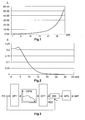
- Fig. 1 of this patent application a corresponding evolution of the Lagrangian multiplier ⁇ being a function of the quantisation parameter QP is depicted. As the QP increases, the algorithm prefers the mode leading to the minimum bit rate.
- the invention relates to the adaptation of a particular coefficient in e.g. H.264 video compression, which coefficient is denoted 'Lagrangian multiplier'.
- ⁇ the Lagrangian multiplier that defines the trade-off between coding/decoding distortion and required bit rate. For a high value of ⁇ the influence of the bit rate is favoured against that of the distortion. For a low value of ⁇ the influence of the distortion is maximised, i.e. the best coding/decoding picture quality is chosen.
- a problem to be solved by the invention is to adapt coefficient ⁇ in the most efficient way in order to achieve the best subjective picture encoding/decoding quality for a given maximum bit rate. This problem is solved by the method disclosed in claim 1. An apparatus that utilises this method is disclosed in claim 2.
- the Lagrange multiplier ⁇ is determined based on the difference between the original input picture and a pre-processed version of the original input picture.
- ⁇ is based on the properties of the human visual system HVS, of which two fundamental properties are taken into account in this invention. Numerous experiments have shown that humans are more sensitive to the contrast of brightness intensities (i.e. to brightness gradients) than to the absolute brightness levels in a picture. Also, humans are very sensitive to spatial frequencies.
- One property of the HVS that is used in the invention is the contrast sensitivity function CSF.
- the CSF depicted in Fig. 2 shows the contrast sensivity S over the spatial frequency measured in cycles per degree. It is an example of an isotropic CSF model.
- the HVS is most sensitive for low spatial frequencies due to the centre/ surround organisation of the visual cells. For higher spatial frequencies the HVS sensitivity S drops rapidly. It is well-known that humans are more sensible to degradations appearing in uniform areas (which correspond to low spatial frequencies) than degradations appearing in textural or detailed areas (which correspond to high spatial frequencies).
- S L ( f ) a 1 ⁇ f 2 ⁇ e ( b 1 ⁇ f c 1 ) + a 2 ⁇ e ( b 2 f c 2 )
- S L is the luminance sensivity
- f is the spatial frequency
- the parameters a 1 to c 2 have the following values Colour space a 1 a 2 b 1 b 2 c 1 c 2
- the opponent colour space consists of three components:
- the source pictures are filtered in frequency domain by a CSF.
- the filtered picture is subtracted from the original picture. Thereafter the corresponding difference signal is weighted by a function giving more importance to the centre of the picture.
- the resulting signal is used for determining the above Lagrange multiplier ⁇ .
- the inventive method is suited for automatically calculating a lamda value controlling the coding mode to be applied in a video signal encoding, wherein said lamda value defines the trade-off between coding/decoding distortion and the bit rate required for coding according to said coding mode, including the steps:
- the inventive apparatus is suited for automatically calculating a lamda value controlling the coding mode to be applied in a video signal encoding, wherein said lamda value defines the trade-off between coding/decoding distortion and the bit rate required for coding according to said coding mode, said apparatus including:
- the Lagrange multiplier is determined using a discrete Fourier transform DFT as shown in Fig. 3.
- the signal i(x,y) of a current input picture PIC is DFT transformed in a stage DFT resulting in a signal I(f), is weighted in a CSF weighting stage CSFW (in order to take into account the greatest sensitivity for the lowest frequencies) resulting in a signal I CSF (f), and is inverse DFT transformed in a stage IDFT resulting in a signal out(x,y) representing the filtered input picture PICF.
- a stage SBS the input picture PIC is subtracted pixelwise from the corresponding pixels of the inverse DFT transformed version of that picture (or vice versa) and the corresponding absolute values of these pixel differences are weighted in a picture centre weighting stage WPC (in order to assign to the centre (x 0 , y 0 ) of the picture a greater importance than to the periphery) leading to a lamda map LMP ( ⁇ (x,y)) for the current picture.
- WPC picture centre weighting stage WPC
- I ( f ) DFT ( i ( x , y ) )
- x and y run over all x and y pixel positions in the picture, in the WPC weighting x 0 and y 0 refer to the centre coordinates of the picture
- ⁇ is a predetermined factor expressed in degrees
- the constant k serves for adapting the strength of the coefficient so as to have the same or a similar dynamic as the above-mentioned
- ⁇ (x, y) The value of ⁇ (x, y) is important for coding areas of the picture. For a high value of ⁇ (x,y) a lower bit rate is favoured in the detriment of the coding/decoding quality. A higher video quality is preferred for the centre region of pictures, a lower video quality is accepted in the remaining areas and for borders of uniform areas.
- the pre-processed version PICF of the original input picture is calculated using a N*N DCT (discrete cosine transform) as shown in Fig. 4.
- N*N DCT discrete cosine transform
- This embodiment can be applied advantageously in picture compressions that are based on pixel block structured processing, like MPEG2 and MPEG4 Video.
- a frequency grouping is carried out in stage FGP. Frequency grouping consists in gathering all the DCT coefficients of a picture having the same frequency.
- frequency grouping will provide N blocks each including M frequency coefficients having the same frequency.
- This is a representation of the frequencies content of a picture which is very useful for applying the CSF weighting in CSF weighting stage CSFW in order to take into account the greatest sensitivity for the lowest frequencies.
- a corresponding frequency de-grouping is carried out in frequency de-grouping stage FDGP in order to get N*N DCT blocks, which are thereafter inverse DCT transformed in one or more inverse transformer stages DCT -1 4x4 thereby providing the filtered input picture PICF.
- the processing continues like in the first embodiment by forming in stage SBS the difference signal between PIC and PICF and picture centre related weighting as shown in Fig. 5. That difference signal is used to calculate the Lamda coefficient L.
- the average value for the CSF function in each interval is computed: [0;6.64] ⁇ 1; [6.64;9.41] ⁇ 0.82; [9.41;13.29] ⁇ 0.48; [13.29;18.66] ⁇ 0.2; [18.66;24.03] ⁇ 0.05; [24.03;28.27] ⁇ 0.01 . 1 0.82 0.2 0.05 0.82 0.48 0.2 0.05 0.2 0.2 0.05 0.01 0.05 0.05 0.01 0.01 0.01 In a video compression like H.264, the calculation of one lambda value ⁇ per macroblock (each including 16*16 luminance pixels) is required.
- This lambda value for a current macroblock can be calculated by forming the average of the 16 values obtained for each DCT block of that current macroblock.
Landscapes
- Engineering & Computer Science (AREA)
- Multimedia (AREA)
- Signal Processing (AREA)
- Compression Or Coding Systems Of Tv Signals (AREA)
Abstract
In video compression it is desirable to characterise the visual content of the images prior to the encoding in order to improve the coding efficiency. This is performed by adapting the Lagrangian multiplier defining a trade-off between coding/decoding distortion and required bit rate. The source pictures are filtered in frequency domain by a contrast sensivity function. The filtered picture is subtracted from the original picture. Thereafter the corresponding difference signal is weighted by a function giving more importance to the centre of the picture. The resulting signal is used for determining the Lagrange multiplier.
Description
- The invention relates to a method and to an apparatus for automatically calculating a lamda value controlling the coding mode to be applied in a video signal encoding, wherein said lamda value defines the trade-off between coding/decoding distortion and the bit rate required for coding according to said coding mode.
- E.g. in the H.264 (ISO/IEC 14496-10
MPEG4 part 10, AVC) video compression it is desirable to analyse or to characterise the visual content of the images prior to the encoding. Using such a-priori information can improve the coding efficiency. For example, MPEG-7 is in the process of specifying a standard in order to describe various types of audio-visual information like cut detection and face detection. - The decision making on different (macroblock) modes in picture sequence encoding is not standardised. In A. Smolic, T. Wiegand, "Long-term Global Motion Compensation for Advanced Video Coding", Heinrich-Hertz-Institute (FHG-HHI), Proc. 10. Dortmunder Fernsehseminar, ITG/FKTG-Fachtagung, Dortmund, Germany, September 2003, the Lagrangian multiplier is adapted as follows:

where QP is the quantisation parameter for a pixel macroblock including the macroblock overhead information (macroblock header, motion vectors, etc.). - In Fig. 1 of this patent application a corresponding evolution of the Lagrangian multiplier λ being a function of the quantisation parameter QP is depicted. As the QP increases, the algorithm prefers the mode leading to the minimum bit rate.
- The invention relates to the adaptation of a particular coefficient in e.g. H.264 video compression, which coefficient is denoted 'Lagrangian multiplier'. The formula in which this coefficient is applied refers to the macroblock coding mode selection based on rate distortion:

wherein J is the coding cost for the coding mode m, D is the distortion or reconstruction error (e.g. the sum of squared differences between the original macroblock and its coded-decoded version) computed for coding mode m, and R is the bit rate required for coding a macroblock in mode m, and λ is the Lagrangian multiplier that defines the trade-off between coding/decoding distortion and required bit rate. For a high value of λ the influence of the bit rate is favoured against that of the distortion. For a low value of λ the influence of the distortion is maximised, i.e. the best coding/decoding picture quality is chosen. - A problem to be solved by the invention is to adapt coefficient λ in the most efficient way in order to achieve the best subjective picture encoding/decoding quality for a given maximum bit rate. This problem is solved by the method disclosed in
claim 1. An apparatus that utilises this method is disclosed in claim 2. - The Lagrange multiplier λ is determined based on the difference between the original input picture and a pre-processed version of the original input picture.
- The determination of λ is based on the properties of the human visual system HVS, of which two fundamental properties are taken into account in this invention. Numerous experiments have shown that humans are more sensitive to the contrast of brightness intensities (i.e. to brightness gradients) than to the absolute brightness levels in a picture. Also, humans are very sensitive to spatial frequencies. One property of the HVS that is used in the invention is the contrast sensitivity function CSF.
- The CSF depicted in Fig. 2 shows the contrast sensivity S over the spatial frequency measured in cycles per degree. It is an example of an isotropic CSF model. The HVS is most sensitive for low spatial frequencies due to the centre/ surround organisation of the visual cells. For higher spatial frequencies the HVS sensitivity S drops rapidly. It is well-known that humans are more sensible to degradations appearing in uniform areas (which correspond to low spatial frequencies) than degradations appearing in textural or detailed areas (which correspond to high spatial frequencies).
- The depicted luminance CSF function is given by:

wherein SL is the luminance sensivity, f is the spatial frequency and the parameters a1 to c2 have the following valuesColour space a1 a2 b1 b2 c1 c2 Opponent 0.205 0.949 -0.923 -0.8 0.781 2.000 YCbCr 0.221 0.997 -0.970 -0.8 0.758 1.999 L*a*b* 0.220 0.996 -0.969 -0.8 0.760 1.995 - The opponent colour space consists of three components:
- A for achromatic;
- Cr1 for red and green component;
- Cr2 for blue and yellow component.
L*a*b* represents an attempt to linearise the perceptibility of colour differences. The non-linear relations for L*, a* and b* are intended to mimic the logarithmic response of the eye. - The second property of the HVS that is used in the invention is deduced from experiments on the direction of the human gaze. Our experiments have shown that the centre of a picture attracts the visual attention even in case that centre is devoid of interesting picture content.
- According to the invention the source pictures are filtered in frequency domain by a CSF. The filtered picture is subtracted from the original picture. Thereafter the corresponding difference signal is weighted by a function giving more importance to the centre of the picture. The resulting signal is used for determining the above Lagrange multiplier λ.
- In principle, the inventive method is suited for automatically calculating a lamda value controlling the coding mode to be applied in a video signal encoding, wherein said lamda value defines the trade-off between coding/decoding distortion and the bit rate required for coding according to said coding mode, including the steps:
- forming a frequency domain representation of an input picture;
- weighting said frequency domain representation of said input picture by a contrast sensivity function;
- forming a time domain representation of said weighted frequency domain representation resulting in a filtered version of said input picture;
- forming a difference signal between said input picture and said filtered input picture;
- weighting said difference signal such that to the values in the picture centre region a greater importance is assigned than to picture regions outside said centre region, by calculating for a current pixel or pixel block or macroblock location said lamda value by multiplying said difference signal with a factor that depends on the distance of said current pixel or pixel block or macroblock location from the centre of said input picture.
- In principle the inventive apparatus is suited for automatically calculating a lamda value controlling the coding mode to be applied in a video signal encoding, wherein said lamda value defines the trade-off between coding/decoding distortion and the bit rate required for coding according to said coding mode, said apparatus including:
- means being adapted for forming a frequency domain representation of an input picture;
- means being adapted for weighting said frequency domain representation of said input picture by a contrast sensivity function;
- means being adapted for forming a time domain representation of said weighted frequency domain representation resulting in a filtered version of said input picture;
- means being adapted for forming a difference signal between said input picture and said filtered input picture;
- means being adapted for weighting said difference signal such that to the values in the picture centre region a greater importance is assigned than to picture regions outside said centre region, by calculating for a current pixel or pixel block or macroblock location said lamda value by multiplying said difference signal with a factor that depends on the distance of said current pixel or pixel block or macroblock location from the centre of said input picture.
- Advantageous additional embodiments of the invention are disclosed in the respective dependent claims.
- Exemplary embodiments of the invention are described with reference to the accompanying drawings, which show in:
- Fig. 1
- evolution of the Lagrangian multiplier λ as a function of the quantisation parameter QP;
- Fig. 2
- contrast sensivity function;
- Fig. 3
- block diagram according to a first embodiment of the invention showing weighting of the source picture by a contrast sensitivity function using a DFT;
- Fig. 4
- block diagram according to a second embodiment of the invention showing weighting of the source picture by a contrast sensitivity function using a 4*4 DCT;
- Fig. 5
- determination of the lambda coefficient from the input and filtered input picture;
- Fig. 6
- normalised contrast sensivity function.
- According to one embodiment of the invention the Lagrange multiplier is determined using a discrete Fourier transform DFT as shown in Fig. 3. The signal i(x,y) of a current input picture PIC is DFT transformed in a stage DFT resulting in a signal I(f), is weighted in a CSF weighting stage CSFW (in order to take into account the greatest sensitivity for the lowest frequencies) resulting in a signal ICSF(f), and is inverse DFT transformed in a stage IDFT resulting in a signal out(x,y) representing the filtered input picture PICF. In a stage SBS the input picture PIC is subtracted pixelwise from the corresponding pixels of the inverse DFT transformed version of that picture (or vice versa) and the corresponding absolute values of these pixel differences are weighted in a picture centre weighting stage WPC (in order to assign to the centre (x0, y0) of the picture a greater importance than to the periphery) leading to a lamda map LMP (λ(x,y)) for the current picture.
- This kind of processing can be expressed as follows:


- For example, a value of 2° (corresponding to 75 pixels if the picture has 720 horizontal pixels in total and 576 vertical pixels in total) can be taken for σ for a viewing distance d = 6*H.
- The value of λ(x, y) is important for coding areas of the picture. For a high value of λ(x,y) a lower bit rate is favoured in the detriment of the coding/decoding quality. A higher video quality is preferred for the centre region of pictures, a lower video quality is accepted in the remaining areas and for borders of uniform areas.
- In a second embodiment of the invention the pre-processed version PICF of the original input picture is calculated using a N*N DCT (discrete cosine transform) as shown in Fig. 4. This embodiment can be applied advantageously in picture compressions that are based on pixel block structured processing, like MPEG2 and MPEG4 Video.
Every N*N pixel block (e.g. N=4 or N=8) of the input picture PIC is DCT transformed in one or more transformer stages DCT4x4 into a corresponding N*N coefficient block. On the resulting frequency domain coefficients a frequency grouping is carried out in stage FGP. Frequency grouping consists in gathering all the DCT coefficients of a picture having the same frequency. For example, if the picture is divided into M DCT blocks (4*4), frequency grouping will provide N blocks each including M frequency coefficients having the same frequency. This is a representation of the frequencies content of a picture which is very useful for applying the CSF weighting in CSF weighting stage CSFW in order to take into account the greatest sensitivity for the lowest frequencies. Following the weighting step, a corresponding frequency de-grouping is carried out in frequency de-grouping stage FDGP in order to get N*N DCT blocks, which are thereafter inverse DCT transformed in one or more inverse transformer stages DCT-14x4 thereby providing the filtered input picture PICF. The processing continues like in the first embodiment by forming in stage SBS the difference signal between PIC and PICF and picture centre related weighting as shown in Fig. 5. That difference signal is used to calculate the Lamda coefficient L. - The DCT applied to N by N pixel sub-blocks is given by :

wherein
- Assuming N = 4, the following family of normalised frequencies of the frequency coefficients is obtained, i.e. for each DCT coefficient its frequency is given in table 1 (the top left position corresponds to the DC coefficient):
0 0.235 0.47 0.7 0.235 0.333 0.52 0.745 0.47 0.52 0.66 0.85 0.7 0.745 0.85 1 - The spatial sampling frequency f S expressed in pixels per degree is given by:

wherein d is the viewing distance measured in meters, R h is the horizontal resolution of the picture and W is the width of the screen.
A simplification occurs if d = β*H with H being the height of the screen. In standard TV viewing H = W*3/4 and β = 6:
0 6.64 13.29 19.79 6.64 9.41 14.70 21.06 13.29 14.70 18.66 24.03 19.79 21.06 24.03 28.27
[0;6.64] ⇒ 1; [6.64;9.41] ⇒ 0.82; [9.41;13.29] ⇒ 0.48; [13.29;18.66] ⇒ 0.2; [18.66;24.03] ⇒ 0.05; [24.03;28.27] ⇒ 0.01 .1 0.82 0.2 0.05 0.82 0.48 0.2 0.05 0.2 0.2 0.05 0.01 0.05 0.05 0.01 0.01 

- The invention achieves the following advantages:
- The determination of the Lagrangian multiplier is based on spatial psycho-visual properties.
- Few thresholds only are required. After the weighting matrix has been defined (cf. the above table) the processing is fully automatic.
- The invention improves the subjective quality at a given constant bit rate. Moreover, the required bit rate can be reduced for a given psycho-visual quality.
Claims (8)
- Method for automatically calculating a lamda value (λ) controlling the coding mode to be applied in a video signal encoding, wherein said lamda value defines the trade-off between coding/decoding distortion and the bit rate required for coding according to said coding mode, characterised by the steps:- forming (DFT, DCT4x4) a frequency domain representation of an input picture (PIC);- weighting (CSFW) said frequency domain representation of said input picture by a contrast sensivity function;- forming (IDFT, DCT-14x4) a time domain representation of said weighted frequency domain representation resulting in a filtered version (PICF) of said input picture;- forming (SBS) a difference signal between said input picture (PIC) and said filtered input picture (PICF);- weighting (WPC) said difference signal such that to the values in the picture centre region (x0, y0) a greater importance is assigned than to picture regions outside said centre region, by calculating for a current pixel or pixel block or macroblock location said lamda value (λ(x, y)) by multiplying said difference signal with a factor that depends on the distance of said current pixel or pixel block or macroblock location from the centre of said input picture.
- Apparatus for automatically calculating a lamda value (λ) controlling the coding mode to be applied in a video signal encoding, wherein said lamda value defines the trade-off between coding/decoding distortion and the bit rate required for coding according to said coding mode, said apparatus including:- means (DFT, DCT4x4) being adapted for forming a frequency domain representation of an input picture (PIC);- means (CSFW) being adapted for weighting said frequency domain representation of said input picture by a contrast sensivity function;- means (IDFT, DCT-14x4) being adapted for forming a time domain representation of said weighted frequency domain representation resulting in a filtered version (PICF) of said input picture;- means (SBS) being adapted for forming a difference signal between said input picture (PIC) and said filtered input picture (PICF);- means (WPC) being adapted for weighting said difference signal such that to the values in the picture centre region (x0, y0) a greater importance is assigned than to picture regions outside said centre region by calculating for a current pixel or pixel block or macroblock location said lamda value (λ(x, y)) by multiplying said difference signal with a factor that depends on the distance of said current pixel or pixel block or macroblock location from the centre of said input picture.
- Method according to claim 1, or apparatus according to claim 2, wherein said lamda value is a Lagrangian multiplier (λ).
- Method according to claim 1 or 3, or apparatus according to claim 2 or 3, wherein said frequency domain representation is formed using a DFT and said time domain representation of said weighted frequency domain representation is formed using an IDFT.
- Method according to claim 1 or 3, or apparatus according to claim 2 or 3, wherein said frequency domain representation is formed using a DCT and said time domain representation of said weighted frequency domain representation is formed using an IDCT.
- Method or apparatus according to claim 5, wherein the coefficients of said DCT are frequency grouped (FGP) by gathering all the DCT coefficients of a picture having the same frequency before being weighted (CSFW) by said contrast sensivity function, and wherein the weighted frequency grouped coefficients are correspondingly degrouped (FDGP) before being inverse DCT transformed.
- Method or apparatus according to claim 6, wherein said DCT and IDCT is a 4*4 or 8*8 DCT or IDCT, respectively.
- Method according to one of claims 1 and 3 to 7, or apparatus according to one of claims 2 to 7, said factor being

wherein x0 and y0 are horizontal and vertical centre positions, respectively, in said input picture, x and y are any horizontal and vertical positions, respectively, in said input picture, and σ is a predetermined factor expressed in degrees.
Priority Applications (1)
| Application Number | Priority Date | Filing Date | Title |
|---|---|---|---|
| EP05300001A EP1677252A1 (en) | 2005-01-03 | 2005-01-03 | Method and apparatus for calculating a lambda value controlling the coding mode in a video encoder. |
Applications Claiming Priority (1)
| Application Number | Priority Date | Filing Date | Title |
|---|---|---|---|
| EP05300001A EP1677252A1 (en) | 2005-01-03 | 2005-01-03 | Method and apparatus for calculating a lambda value controlling the coding mode in a video encoder. |
Publications (1)
| Publication Number | Publication Date |
|---|---|
| EP1677252A1 true EP1677252A1 (en) | 2006-07-05 |
Family
ID=34942482
Family Applications (1)
| Application Number | Title | Priority Date | Filing Date |
|---|---|---|---|
| EP05300001A Withdrawn EP1677252A1 (en) | 2005-01-03 | 2005-01-03 | Method and apparatus for calculating a lambda value controlling the coding mode in a video encoder. |
Country Status (1)
| Country | Link |
|---|---|
| EP (1) | EP1677252A1 (en) |
Cited By (5)
| Publication number | Priority date | Publication date | Assignee | Title |
|---|---|---|---|---|
| EP2061254A2 (en) | 2007-09-14 | 2009-05-20 | Sony Corporation | Video coding |
| CN101674480B (en) * | 2009-10-21 | 2012-08-08 | 浙江宇视科技有限公司 | Method and device for selecting encoding modes |
| WO2018175215A1 (en) * | 2017-03-23 | 2018-09-27 | Qualcomm Incorporated | Adaptive parameters for coding of 360-degree video |
| CN113850879A (en) * | 2021-06-01 | 2021-12-28 | 天翼智慧家庭科技有限公司 | Method for improving compression ratio of static background video based on background modeling technology |
| US20240187618A1 (en) * | 2020-05-19 | 2024-06-06 | Google Llc | Multivariate rate control for transcoding video content |
Citations (2)
| Publication number | Priority date | Publication date | Assignee | Title |
|---|---|---|---|---|
| WO1997037322A1 (en) * | 1996-03-29 | 1997-10-09 | Sarnoff Corporation | Apparatus and method for optimizing encoding and performing automated steerable image compression using a perceptual metric |
| WO1999043161A1 (en) * | 1998-02-21 | 1999-08-26 | Tandberg Television Limited | Determining visually noticeable differences between two images |
-
2005
- 2005-01-03 EP EP05300001A patent/EP1677252A1/en not_active Withdrawn
Patent Citations (2)
| Publication number | Priority date | Publication date | Assignee | Title |
|---|---|---|---|---|
| WO1997037322A1 (en) * | 1996-03-29 | 1997-10-09 | Sarnoff Corporation | Apparatus and method for optimizing encoding and performing automated steerable image compression using a perceptual metric |
| WO1999043161A1 (en) * | 1998-02-21 | 1999-08-26 | Tandberg Television Limited | Determining visually noticeable differences between two images |
Non-Patent Citations (6)
| Title |
|---|
| ALBANESI M G ET AL: "Adaptive image compression based on regions of interest and a modified contrast sensitivity function", PATTERN RECOGNITION, 2000. PROCEEDINGS. 15TH INTERNATIONAL CONFERENCE ON SEPTEMBER 3-7, 2000, LOS ALAMITOS, CA, USA,IEEE COMPUT. SOC, US, vol. 3, 3 September 2000 (2000-09-03), pages 215 - 218, XP010533267, ISBN: 0-7695-0750-6 * |
| CHUN-HSIEN CHOU, YUN-CHIN LI: "A perceptually tuned subband image coder based on the measure of just-noticeable-distortion profile", IEEE TRANSACTIONS ON CIRCUITS AND SYSTEMS FOR VIDEO TECHNOLOGY, vol. 5, no. 6, 1 December 1995 (1995-12-01), pages 467 - 476, XP002332899, Retrieved from the Internet <URL:http://ieeexplore.ieee.org/iel4/76/10143/00475889.pdf?tp=&arnumber=475889&isnumber=10143> [retrieved on 20050621] * |
| NADENAU, M.J.; REICHEL, J.; KUNT, M.;: "Wavelet-based color image compression: exploiting the contrast sensitivity function", IEEE TRANSACTIONS ON IMAGE PROCESSING, vol. 12, no. 1, 2003, pages 58 - 70, XP002332897, Retrieved from the Internet <URL:http://ieeexplore.ieee.org/iel5/83/26630/01187359.pdf?tp=&arnumber=1187359&isnumber=26630> [retrieved on 20050621] * |
| YAN YANG ET AL: "Rate-distortion optimizations for region and object based wavelet video coding", SIGNALS, SYSTEMS AND COMPUTERS, 2000. CONFERENCE RECORD OF THE THIRTY-FOURTH ASILOMAR CONFERENCE ON OCT. 29 - NOV. 1, 2000, PISCATAWAY, NJ, USA,IEEE, vol. 2, 29 October 2000 (2000-10-29), pages 1363 - 1368, XP010535223, ISBN: 0-7803-6514-3 * |
| YANG X K ET AL: "On incorporating just-noticeable-distortion profile into motion-compensatfd prediction for video compression", PROCEEDINGS 2003 INTERNATIONAL CONFERENCE ON IMAGE PROCESSING. ICIP-2003. BARCELONA, SPAIN, SEPT. 14 - 17, 2003, INTERNATIONAL CONFERENCE ON IMAGE PROCESSING, NEW YORK, NY : IEEE, US, vol. VOL. 2 OF 3, 14 September 2003 (2003-09-14), pages 833 - 836, XP010669963, ISBN: 0-7803-7750-8 * |
| ZHOU WANG, ALAN C. BOVIK , LIGANG LU, JACK L. KOULOHERIS: "Foveated wavelet image quality index", PROCEEDINGS OF SPIE, vol. 4472, 2001, pages 42 - 52, XP002332898, Retrieved from the Internet <URL:http://spiedl.aip.org/getpdf/servlet/GetPDFServlet?filetype=pdf&id=PSISDG004472000001000042000001&idtype=cvips&prog=search> [retrieved on 20050621] * |
Cited By (9)
| Publication number | Priority date | Publication date | Assignee | Title |
|---|---|---|---|---|
| EP2061254A2 (en) | 2007-09-14 | 2009-05-20 | Sony Corporation | Video coding |
| EP2061254A3 (en) * | 2007-09-14 | 2011-11-02 | Sony Corporation | Video coding |
| CN101674480B (en) * | 2009-10-21 | 2012-08-08 | 浙江宇视科技有限公司 | Method and device for selecting encoding modes |
| WO2018175215A1 (en) * | 2017-03-23 | 2018-09-27 | Qualcomm Incorporated | Adaptive parameters for coding of 360-degree video |
| CN110447226A (en) * | 2017-03-23 | 2019-11-12 | 高通股份有限公司 | Adaptive parameters for decoding 360-degree video |
| US10904531B2 (en) | 2017-03-23 | 2021-01-26 | Qualcomm Incorporated | Adaptive parameters for coding of 360-degree video |
| US20240187618A1 (en) * | 2020-05-19 | 2024-06-06 | Google Llc | Multivariate rate control for transcoding video content |
| US12501061B2 (en) * | 2020-05-19 | 2025-12-16 | Google Llc | Multivariate rate control for transcoding video content |
| CN113850879A (en) * | 2021-06-01 | 2021-12-28 | 天翼智慧家庭科技有限公司 | Method for improving compression ratio of static background video based on background modeling technology |
Similar Documents
| Publication | Publication Date | Title |
|---|---|---|
| Xiao | DCT-based video quality evaluation | |
| US5654759A (en) | Methods and apparatus for reducing blockiness in decoded video | |
| Wu et al. | Perceptual visual signal compression and transmission | |
| Wang et al. | Perceptual video coding based on SSIM-inspired divisive normalization | |
| EP2532161B1 (en) | De-blocking filtering control | |
| US6898321B1 (en) | Method and apparatus for blocking effect reduction | |
| US9538201B2 (en) | Filtering method for removing block artifacts and/or ringing noise and apparatus therefor | |
| US9805287B2 (en) | Method of identifying relevant areas in digital images, method of encoding digital images, and encoder system | |
| US6535555B1 (en) | Quantizing method and device for video compression | |
| Luo et al. | H. 264/advanced video control perceptual optimization coding based on JND-directed coefficient suppression | |
| US6782135B1 (en) | Apparatus and methods for adaptive digital video quantization | |
| EP2618574B1 (en) | Quantization matrix design for HEVC standard | |
| Rosenholtz et al. | Perceptual adaptive JPEG coding | |
| US6983078B2 (en) | System and method for improving image quality in processed images | |
| Rehman et al. | SSIM-inspired perceptual video coding for HEVC | |
| US20150023420A1 (en) | Image decoding device, image encoding device, image decoding method, and image encoding method | |
| US7574060B2 (en) | Deblocker for postprocess deblocking | |
| EP0960528A2 (en) | Method of frame by frame calculation of quantization matrices | |
| US20230362377A1 (en) | Systems, methods, and apparatuses for processing video | |
| JP3105335B2 (en) | Compression / expansion method by orthogonal transform coding of image | |
| US20040005077A1 (en) | Anti-compression techniques for visual images | |
| Chou et al. | Colour image compression based on the measure of just noticeable colour difference | |
| Wei et al. | Spatial just noticeable distortion profile for image in DCT domain | |
| Li et al. | Perceptually-lossless image coding based on foveated-JND and H. 265/HEVC | |
| Ahumada, Jr et al. | A visual detection model for DCT coefficient quantization |
Legal Events
| Date | Code | Title | Description |
|---|---|---|---|
| PUAI | Public reference made under article 153(3) epc to a published international application that has entered the european phase |
Free format text: ORIGINAL CODE: 0009012 |
|
| AK | Designated contracting states |
Kind code of ref document: A1 Designated state(s): AT BE BG CH CY CZ DE DK EE ES FI FR GB GR HU IE IS IT LI LT LU MC NL PL PT RO SE SI SK TR |
|
| AX | Request for extension of the european patent |
Extension state: AL BA HR LV MK YU |
|
| AKX | Designation fees paid | ||
| STAA | Information on the status of an ep patent application or granted ep patent |
Free format text: STATUS: THE APPLICATION IS DEEMED TO BE WITHDRAWN |
|
| 18D | Application deemed to be withdrawn |
Effective date: 20070106 |
|
| REG | Reference to a national code |
Ref country code: DE Ref legal event code: 8566 |