EP1677120A1 - Method and apparatus for verifying connectivity of an instrumentation system - Google Patents
Method and apparatus for verifying connectivity of an instrumentation system Download PDFInfo
- Publication number
- EP1677120A1 EP1677120A1 EP05256341A EP05256341A EP1677120A1 EP 1677120 A1 EP1677120 A1 EP 1677120A1 EP 05256341 A EP05256341 A EP 05256341A EP 05256341 A EP05256341 A EP 05256341A EP 1677120 A1 EP1677120 A1 EP 1677120A1
- Authority
- EP
- European Patent Office
- Prior art keywords
- electrical signal
- sensor
- instrumentation system
- signal
- measurement means
- Prior art date
- Legal status (The legal status is an assumption and is not a legal conclusion. Google has not performed a legal analysis and makes no representation as to the accuracy of the status listed.)
- Granted
Links
- 238000000034 method Methods 0.000 title claims abstract description 14
- 238000005259 measurement Methods 0.000 claims abstract description 30
- 238000012360 testing method Methods 0.000 claims abstract description 10
- 230000001939 inductive effect Effects 0.000 claims abstract description 3
- 238000010998 test method Methods 0.000 claims abstract description 3
- 230000007274 generation of a signal involved in cell-cell signaling Effects 0.000 claims description 14
- 230000003321 amplification Effects 0.000 claims description 4
- 238000003199 nucleic acid amplification method Methods 0.000 claims description 4
- 230000005284 excitation Effects 0.000 description 4
- 230000003068 static effect Effects 0.000 description 4
- RYGMFSIKBFXOCR-UHFFFAOYSA-N Copper Chemical compound [Cu] RYGMFSIKBFXOCR-UHFFFAOYSA-N 0.000 description 2
- 229910052802 copper Inorganic materials 0.000 description 2
- 239000010949 copper Substances 0.000 description 2
- 239000012790 adhesive layer Substances 0.000 description 1
- 238000004458 analytical method Methods 0.000 description 1
- 230000003466 anti-cipated effect Effects 0.000 description 1
- 230000005672 electromagnetic field Effects 0.000 description 1
- 239000011888 foil Substances 0.000 description 1
- 238000003780 insertion Methods 0.000 description 1
- 230000037431 insertion Effects 0.000 description 1
- 238000007689 inspection Methods 0.000 description 1
- 239000012212 insulator Substances 0.000 description 1
- 239000002184 metal Substances 0.000 description 1
- 229910052751 metal Inorganic materials 0.000 description 1
- 238000012544 monitoring process Methods 0.000 description 1
Images


Classifications
-
- G—PHYSICS
- G01—MEASURING; TESTING
- G01R—MEASURING ELECTRIC VARIABLES; MEASURING MAGNETIC VARIABLES
- G01R31/00—Arrangements for testing electric properties; Arrangements for locating electric faults; Arrangements for electrical testing characterised by what is being tested not provided for elsewhere
- G01R31/28—Testing of electronic circuits, e.g. by signal tracer
- G01R31/282—Testing of electronic circuits specially adapted for particular applications not provided for elsewhere
- G01R31/2829—Testing of circuits in sensor or actuator systems
-
- G—PHYSICS
- G01—MEASURING; TESTING
- G01D—MEASURING NOT SPECIALLY ADAPTED FOR A SPECIFIC VARIABLE; ARRANGEMENTS FOR MEASURING TWO OR MORE VARIABLES NOT COVERED IN A SINGLE OTHER SUBCLASS; TARIFF METERING APPARATUS; MEASURING OR TESTING NOT OTHERWISE PROVIDED FOR
- G01D3/00—Indicating or recording apparatus with provision for the special purposes referred to in the subgroups
- G01D3/08—Indicating or recording apparatus with provision for the special purposes referred to in the subgroups with provision for safeguarding the apparatus, e.g. against abnormal operation, against breakdown
-
- G—PHYSICS
- G01—MEASURING; TESTING
- G01R—MEASURING ELECTRIC VARIABLES; MEASURING MAGNETIC VARIABLES
- G01R31/00—Arrangements for testing electric properties; Arrangements for locating electric faults; Arrangements for electrical testing characterised by what is being tested not provided for elsewhere
- G01R31/50—Testing of electric apparatus, lines, cables or components for short-circuits, continuity, leakage current or incorrect line connections
- G01R31/66—Testing of connections, e.g. of plugs or non-disconnectable joints
- G01R31/67—Testing the correctness of wire connections in electric apparatus or circuits
Definitions
- the present invention relates to a method and apparatus for verifying connectivity of instrumentation systems.
- the present invention is suited to instrumentations systems which utilise strain gauges.
- Instrumentation systems used, for example, in testing of gas turbine engines comprise a large number of sensors, applied to the gas turbine engine as and where an conditions are to be monitored during operation of the engine. Such sensors typically modify an electrical signal passing through them to indicate conditions. These signals are measured with electrical signal measurement means, such as an ammeter or oscilloscope. Such measurement means are linked directly to the sensors by electrical wires or remotely, via transducer means. By measuring the amount the signal is modified by the sensor, conditions at the sensor location are deduced.
- a typical test engine will have a large number of sensors applied throughout. Because the sensors are needed to determine conditions of components located within the gas turbine engine, the sensors must be applied during engine build. Wires called 'lead-outs' are provided which extend from the sensor to the engine exterior, and which carry an electrical signal to the sensor and from the sensor. Once fully assembled, the engine is taken to a test facility, and the lead-outs are connected to the externally located electrical signal measurement means and signal generation means.
- the present invention provides method and means for checking connectivity of an instrumentation system which addresses the problems set out above.
- a method of testing connectivity of an instrumentation system comprising a plurality of sensors attached to a test piece, each of said sensors provided with electrical signal generating means and electrical signal measurement means, wherein each sensor is located remotely from its electrical signal measurement means, and connected thereto by connecting means, the method comprising the steps of; inducing an electrical signal in a first sensor, checking that the electric signal is received in the corresponding signal measurement means.
- apparatus for testing the connectivity of an instrumentation system comprising an electromagnet and signal generation means for supplying an alternating current to the electromagnet.
- FIG. 1 there is shown a cross-section through a first stage 2 of a gas turbine engine compressor.
- the stage comprises a rotative stage 3 comprising an annular array of compressor blades 4 which are cantilevered at their radially inner ends 6 from a rotatable hub 8, which is driven by a shaft (not shown).
- a static stage 10 comprising an annular array of stators 12 cantilevered from their radially outer ends 14 from the engine casing 16, which comprises an annular duct, which extends forward to bound the rotatable stage 3.
- the engine casing is provided with a number of sealed boroscope apertures 17, which can be opened to allow insertion of a boroscope (not shown) into the engine.
- the first stage 2 is provided with a first and second strain gauge 18,20, an example of which is shown in more detail at Figure 2.
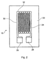
- FIG 2 shows the bonded resistance strain gauge 18 of Figure 1 in more detail.
- the gauge 18 comprises a metal foil element 24, which extends between a first terminal 26 and a second terminal 28.
- the element comprises a single continuous element, comprising a a plurality of elongate parallel elements 30 joined in series by short bridging elements 32.
- the element 24 is bonded to the compressor blade 4 by an adhesive layer that transmits strain from the blade 4 to the element 24 so that strain of the component in the major axis of the elongate elements 30 causes the elements to 'neck'.
- strain gauge 18 This results in a measurable change in the resistance of the gauge 18 whereas strain of the component in the direction of the short 'bridging elements' causes negligible change in resistance of the element 24.
- the resultant 'directionality' of the strain gauge enables direction of strain as well as magnitude to be measured where the gauge 18 is used in conjunction with a second gauge 20, located normal thereto, as shown in Figure 1.
- each strain gauge is attached to 'lead outs' 34,36 which comprise electrical wires.
- These wires are attached to the aerofoil and fed radially inwards to the hub 6 of the first rotatable stage 3 and then pass downstream, towards the static stage 10. They are attached to wires on the static stage via a slip ring arrangement 38 which ensures relative rotational movement between rotatable and static stages 3,10. The wires then feed radially outwards via a stator vane 12 and then pass through a hole 40 in the engine casing.
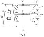
- the wires are terminated by connecting means 46 suitable for attachment to the rest of the instrumentation system. This is shown schematically in Figure 3.
- FIG. 3 shows, schematically, an instrumentation system 41.
- the system comprises first and second strain gauges 18,20, fitted to a compressor aerofoil 4.
- Each gauge is provided with a pair of lead-outs 34a,34b,36a,36b which terminate outside of the engine casing (not shown).
- Each gauge is attached via its respective lead-outs to an individual signal generation means 42,44 in the present example a DC power source, and also to individual signal measurement means 50,52 via a connector 46,48.
- each signal generation means 42,44 provides an electric signal, which passes through the strain gauges 18,20.
- the signal measurement means 50,52 measures the current in the circuit formed between the signal generation means 42,44 and the strain gauges 18,20.
- the first and second gauges 18,20 are also deformed.
- Each gauge 18,20 will modify the electrical signal in its respective circuit. From the measured change, the strain applied to the component 4 can then be calculated. By interpolating the results from each gauge 18,20, the direction of strain can be derived.
- an electrical signal is induced into a first strain gauge 18 of the system, after connection of the lead outs 34,36.
- the appropriate signal measurement means 42 is then checked to ensure that the strain gauge is, as desired, attached to that measurement means 42. It will be understood that where the electrical signal is not detected by the anticipated signal measurement means 42, the remaining signal measurement means 44 may then be checked to see which measurement means has been incorrectly connected to the strain gauge being excited. The gauges can then be reconnected correctly.
- strain gauges 20 are then checked in the same manner.
- the signal measurement means 42,44 are provided with amplification means to boost the signal for measurement
- the signal measured can be compared with a predetermined signal, and the amplification adjusted where needs be, so that a correct signal amplitude is measured.
- the present method can be used to calibrate an instrumentation system 41.
- the diameter of the coil 56 and tubing 60 are sized such that the apparatus 54 as a whole can be inserted into the engine via the boroscope holes 17 located in the duct 16. In this way, the coil 56 can be placed in proximity to gauges 18,20 not readily accessible from either the engine intake or exhaust (not shown).
- the apparatus 54 is passed through a boroscope 17 to lie adjacent a strain gauge 18.
- the apparatus signal generation means 66 is used to generate an alternating electrical signal which passes through the coil 56 and produces an oscillating electro-magnetic field. This induces in the strain gauge 18 a corresponding electrical signal.
- An advantage of the present apparatus 54 is that the size of the electrical signal is proportional to the distance between the apparatus 54 and gauge 18. Hence, even where strain gauges 18,20 are located in close proximity, the gauge immediately adjacent the apparatus 54 will produce a larger signal than that produced by the other, more distant sensor. This enables identification at the signal measurement means 42,44 where the largest measured signal will indicate the measurement means 42,44 attached to the gauge 18 immediately adjacent the apparatus 54.
- the apparatus is particularly well suited for use in conjunction with strain gauges, it will be understood that the apparatus can be used with other electrically conductive sensor to induce an electrical signal therein.
- the alternating electric signal supplied by the signal generation means 66 has a distinct waveform, which is non-sinusoidal, for example a 'two-tone' signal.
- This induces a distinct electrical signal in the instrumentation system which is quite different to the sinusoidal signal associated with mechanical excitation of the strain gauges. In this way, the signal cannot be confused with signals produced by accidental excitation of the engine component.
- the frequency of the alternating electric signal is chosen to be well above any natural resonant frequency of engine components.
- a frequency of 16 KHz is chosen as this is well away from the natural blade frequency.
Landscapes
- Physics & Mathematics (AREA)
- General Physics & Mathematics (AREA)
- Electromagnetism (AREA)
- Engineering & Computer Science (AREA)
- General Engineering & Computer Science (AREA)
- Measurement Of Length, Angles, Or The Like Using Electric Or Magnetic Means (AREA)
Abstract
Description
- The present invention relates to a method and apparatus for verifying connectivity of instrumentation systems. In particular, the present invention is suited to instrumentations systems which utilise strain gauges.
- Instrumentation systems used, for example, in testing of gas turbine engines comprise a large number of sensors, applied to the gas turbine engine as and where an conditions are to be monitored during operation of the engine. Such sensors typically modify an electrical signal passing through them to indicate conditions. These signals are measured with electrical signal measurement means, such as an ammeter or oscilloscope. Such measurement means are linked directly to the sensors by electrical wires or remotely, via transducer means. By measuring the amount the signal is modified by the sensor, conditions at the sensor location are deduced.
- A typical test engine will have a large number of sensors applied throughout. Because the sensors are needed to determine conditions of components located within the gas turbine engine, the sensors must be applied during engine build. Wires called 'lead-outs' are provided which extend from the sensor to the engine exterior, and which carry an electrical signal to the sensor and from the sensor. Once fully assembled, the engine is taken to a test facility, and the lead-outs are connected to the externally located electrical signal measurement means and signal generation means.
- The large number of lead-outs which must be connected to the instrumentation system, 256 is common, can lead to the wrong sensors being connected to the wrong electrical signal measurement means and the wrong electrical signal generation means. At the least, connection of the wrong sensor to the wrong measurement means can lead to erroneous data being gathered, resulting in time consuming analysis. In a worst case, an entire test can be rendered useless, at great expense.
- It is known in the art to check connectivity of an instrumentation system, i.e. that the correct sensor lead-outs are joined to the correct signal generation means and signal measurement means, by mechanically exciting the engine adjacent individual sensors, where such sensors are strain gauges, and monitoring the associated signal measurement means for a response. However, this method has a number of drawbacks. First, sensors and their lead-outs tend to be sensitive components. Injudicious use of force can lead to damage. Second, it is typical to have a number of sensors on a particular component of a gas turbine engine. Excitation of a single sensor in such a situation is difficult, particularly where the component is cantilevered from the main engine structure, as is the case with an aerofoil blade. Third, the sensors are often located deep within the engine, preventing access for mechanical excitation.
- The present invention provides method and means for checking connectivity of an instrumentation system which addresses the problems set out above.
- According to the present invention there is provided a method of testing connectivity of an instrumentation system, said instrumentation system comprising a plurality of sensors attached to a test piece, each of said sensors provided with electrical signal generating means and electrical signal measurement means, wherein each sensor is located remotely from its electrical signal measurement means, and connected thereto by connecting means, the method comprising the steps of;
inducing an electrical signal in a first sensor,
checking that the electric signal is received in the corresponding signal measurement means. - According to a further aspect of the present invention there is provided apparatus for testing the connectivity of an instrumentation system, the apparatus comprising an electromagnet and signal generation means for supplying an alternating current to the electromagnet.
- The invention will now be described in more detail with reference to the accompanying drawings in which;
- Figure 1 shows a cross-section through a first stage of a gas turbine engine compressor;
- Figure 2 shows a bonded resistance strain gauge;
- Figure 3 shows a schematic view of an instrumentation system fitted to the gas turbine engine compressor of Figure 1; and
- Figure 4 shows apparatus for testing the connectivity of an instrumentation system.
- Turning to Figure 1, there is shown a cross-section through a
first stage 2 of a gas turbine engine compressor. The stage comprises arotative stage 3 comprising an annular array ofcompressor blades 4 which are cantilevered at their radiallyinner ends 6 from arotatable hub 8, which is driven by a shaft (not shown). Immediately downstream of therotatable stage 3 is astatic stage 10 comprising an annular array ofstators 12 cantilevered from their radiallyouter ends 14 from theengine casing 16, which comprises an annular duct, which extends forward to bound therotatable stage 3. The engine casing is provided with a number of sealedboroscope apertures 17, which can be opened to allow insertion of a boroscope (not shown) into the engine. - The
first stage 2 is provided with a first andsecond strain gauge - Figure 2 shows the bonded
resistance strain gauge 18 of Figure 1 in more detail. Such gauges are used to measure strain and are used extensively in a variety of other sensor applications such as pressure sensors, load sensors and torque sensors. Thegauge 18 comprises ametal foil element 24, which extends between afirst terminal 26 and asecond terminal 28. The element comprises a single continuous element, comprising a a plurality of elongateparallel elements 30 joined in series byshort bridging elements 32. Theelement 24 is bonded to thecompressor blade 4 by an adhesive layer that transmits strain from theblade 4 to theelement 24 so that strain of the component in the major axis of theelongate elements 30 causes the elements to 'neck'. This results in a measurable change in the resistance of thegauge 18 whereas strain of the component in the direction of the short 'bridging elements' causes negligible change in resistance of theelement 24. The resultant 'directionality' of the strain gauge enables direction of strain as well as magnitude to be measured where thegauge 18 is used in conjunction with asecond gauge 20, located normal thereto, as shown in Figure 1. - Referring back to Figure 1, the
terminals hub 6 of the firstrotatable stage 3 and then pass downstream, towards thestatic stage 10. They are attached to wires on the static stage via aslip ring arrangement 38 which ensures relative rotational movement between rotatable andstatic stages stator vane 12 and then pass through ahole 40 in the engine casing. The wires are terminated by connectingmeans 46 suitable for attachment to the rest of the instrumentation system. This is shown schematically in Figure 3. - Figure 3 shows, schematically, an
instrumentation system 41. The system comprises first andsecond strain gauges compressor aerofoil 4. Each gauge is provided with a pair of lead-outs connector - In operation, each signal generation means 42,44 provides an electric signal, which passes through the
strain gauges strain gauges aerofoil 4 is strained, the first andsecond gauges gauge component 4 can then be calculated. By interpolating the results from eachgauge - To ensure that the
correct strain gauge first strain gauge 18 of the system, after connection of thelead outs - The
remaining strain gauges 20 are then checked in the same manner. - In the present case, there are only two
gauges instrumentation system 41 wherein a plurality of sensors are used in conjunction with a plurality of signal measurement means. - In a further mode of operation, where the signal measurement means 42,44 are provided with amplification means to boost the signal for measurement, the signal measured can be compared with a predetermined signal, and the amplification adjusted where needs be, so that a correct signal amplitude is measured. In this manner, the present method can be used to calibrate an
instrumentation system 41. -
Apparatus 54 used to induce the electrical signal in thestrain gauge apparatus 54 comprises acopper coil 56 wrapped around aplastic insulator 58. Thecoil 56 is 8mm in diameter and 3mm deep. It is bonded to a length oftubing 60 of about the same diameter, andwires copper coil 56 to signal generation means 66. Thetube 60 is at least as long as the distance between the strain gauges 18,20 and theengine duct 16. Preferably thetubing 60 is clear to permit inspection of thewires coil 56. - The diameter of the
coil 56 andtubing 60 are sized such that theapparatus 54 as a whole can be inserted into the engine via the boroscope holes 17 located in theduct 16. In this way, thecoil 56 can be placed in proximity togauges - In use, the
apparatus 54 is passed through aboroscope 17 to lie adjacent astrain gauge 18. The apparatus signal generation means 66 is used to generate an alternating electrical signal which passes through thecoil 56 and produces an oscillating electro-magnetic field. This induces in the strain gauge 18 a corresponding electrical signal. An advantage of thepresent apparatus 54 is that the size of the electrical signal is proportional to the distance between theapparatus 54 andgauge 18. Hence, even where strain gauges 18,20 are located in close proximity, the gauge immediately adjacent theapparatus 54 will produce a larger signal than that produced by the other, more distant sensor. This enables identification at the signal measurement means 42,44 where the largest measured signal will indicate the measurement means 42,44 attached to thegauge 18 immediately adjacent theapparatus 54. - Although it will be understood that the apparatus is particularly well suited for use in conjunction with strain gauges, it will be understood that the apparatus can be used with other electrically conductive sensor to induce an electrical signal therein.
- Preferably, the alternating electric signal supplied by the signal generation means 66 has a distinct waveform, which is non-sinusoidal, for example a 'two-tone' signal. This induces a distinct electrical signal in the instrumentation system which is quite different to the sinusoidal signal associated with mechanical excitation of the strain gauges. In this way, the signal cannot be confused with signals produced by accidental excitation of the engine component.
- Similarly, the frequency of the alternating electric signal is chosen to be well above any natural resonant frequency of engine components. In the present example, a frequency of 16 KHz is chosen as this is well away from the natural blade frequency.
Claims (7)
- A method of testing connectivity of an instrumentation system, said instrumentation system comprising a plurality of sensors attached to a test piece, each of said sensors provided with electrical signal generating means and electrical signal measurement means, wherein each sensor is located remotely from its electrical signal measurement means, and connected thereto by connecting means, the method comprising the steps of;
inducing an electrical signal in a first sensor,
checking that the electric signal is received in the corresponding signal measurement means. - A method as claimed in claim 1 wherein the electrical signal is generated in the first sensor using an oscillating magnetic field.
- A method as claimed in claim 2 wherein the oscillating magnetic field is generated using an electromagnet driven by an oscillating current.
- A method as claimed in claim 3 wherein the oscillating current used has a distinct, non-sinusoidal waveform.
- A method as claimed in claim 1 wherein the instrumentation system further comprises at least one amplification means between a first sensor and first electrical signal measurement means, and the method comprises the further step of using a predetermined oscillating magnetic field, and comparing the electric signal induced in the first sensor, via the electrical signal measuring means, with a predetermined output, and adjusting the amplification means to calibrate the sensor.
- Apparatus for testing the connectivity of an instrumentation system, the apparatus comprising an electromagnet and signal generation means for supplying an alternating current to the electromagnet.
- Apparatus as claimed in claim 6 wherein the signal generation means comprises a two-tone signal generation means.
Applications Claiming Priority (1)
| Application Number | Priority Date | Filing Date | Title |
|---|---|---|---|
| US61725504P | 2004-10-12 | 2004-10-12 |
Publications (2)
| Publication Number | Publication Date |
|---|---|
| EP1677120A1 true EP1677120A1 (en) | 2006-07-05 |
| EP1677120B1 EP1677120B1 (en) | 2008-10-29 |
Family
ID=34079684
Family Applications (1)
| Application Number | Title | Priority Date | Filing Date |
|---|---|---|---|
| EP05256341A Expired - Lifetime EP1677120B1 (en) | 2004-10-12 | 2005-10-12 | Method and apparatus for verifying connectivity of an instrumentation system |
Country Status (4)
| Country | Link |
|---|---|
| US (1) | US7135867B2 (en) |
| EP (1) | EP1677120B1 (en) |
| DE (1) | DE602005010656D1 (en) |
| GB (1) | GB0427149D0 (en) |
Cited By (1)
| Publication number | Priority date | Publication date | Assignee | Title |
|---|---|---|---|---|
| CN105716870A (en) * | 2016-02-03 | 2016-06-29 | 广东电网有限责任公司电力科学研究院 | Installation assembly of instrument for measuring performance of compressor on line |
Families Citing this family (5)
| Publication number | Priority date | Publication date | Assignee | Title |
|---|---|---|---|---|
| US7617670B2 (en) * | 2006-03-31 | 2009-11-17 | Lockheed Martin Corporation | Flow control redistribution to mitigate high cycle fatigue |
| GB2504612B (en) | 2011-05-09 | 2014-09-24 | Rolls Royce Plc | An apparatus for supporting a tool in an assembled apparatus |
| FR2996875A1 (en) * | 2012-10-12 | 2014-04-18 | Snecma | INSTALLATION OF MEASUREMENTS FOR BREAKING TESTS ON A TURBOMACHINE |
| US20170342910A1 (en) * | 2016-05-25 | 2017-11-30 | General Electric Company | Attachment system for a gas turbine engine |
| US10612992B2 (en) | 2017-11-03 | 2020-04-07 | Lockheed Martin Corporation | Strain gauge detection and orientation system |
Citations (3)
| Publication number | Priority date | Publication date | Assignee | Title |
|---|---|---|---|---|
| US3840802A (en) * | 1972-08-10 | 1974-10-08 | Rockwell International Corp | Mutual inductance coupling probe for testing the integrity of through-hole plating in printed circuit boards |
| US4998059A (en) * | 1990-03-28 | 1991-03-05 | The United States Of America As Represented By The Secretary Of The Navy | Dual demodulating circuit tracer |
| GB2245709A (en) * | 1990-06-30 | 1992-01-08 | Rolls Royce Plc | Dual readout temperature and strain sensor combinations |
Family Cites Families (4)
| Publication number | Priority date | Publication date | Assignee | Title |
|---|---|---|---|---|
| DE4012839B4 (en) * | 1989-04-26 | 2004-02-26 | Atg Test Systems Gmbh & Co.Kg | Method and test device for testing electrical or electronic devices under test |
| US6621831B1 (en) * | 1999-01-05 | 2003-09-16 | Legerity, Inc. | Method and apparatus for verifying and correcting connectivity |
| US6590398B1 (en) * | 2000-07-06 | 2003-07-08 | Honeywell Advanced Circuits, Inc. | Fixture-less bare board tester |
| US20050198272A1 (en) * | 2004-02-23 | 2005-09-08 | Bernard Marc R. | System, method, and apparatus for connectivity testing |
-
2004
- 2004-12-13 GB GBGB0427149.0A patent/GB0427149D0/en not_active Ceased
-
2005
- 2005-10-11 US US11/246,518 patent/US7135867B2/en not_active Expired - Fee Related
- 2005-10-12 DE DE602005010656T patent/DE602005010656D1/en not_active Expired - Lifetime
- 2005-10-12 EP EP05256341A patent/EP1677120B1/en not_active Expired - Lifetime
Patent Citations (3)
| Publication number | Priority date | Publication date | Assignee | Title |
|---|---|---|---|---|
| US3840802A (en) * | 1972-08-10 | 1974-10-08 | Rockwell International Corp | Mutual inductance coupling probe for testing the integrity of through-hole plating in printed circuit boards |
| US4998059A (en) * | 1990-03-28 | 1991-03-05 | The United States Of America As Represented By The Secretary Of The Navy | Dual demodulating circuit tracer |
| GB2245709A (en) * | 1990-06-30 | 1992-01-08 | Rolls Royce Plc | Dual readout temperature and strain sensor combinations |
Cited By (2)
| Publication number | Priority date | Publication date | Assignee | Title |
|---|---|---|---|---|
| CN105716870A (en) * | 2016-02-03 | 2016-06-29 | 广东电网有限责任公司电力科学研究院 | Installation assembly of instrument for measuring performance of compressor on line |
| CN105716870B (en) * | 2016-02-03 | 2018-07-27 | 广东电网有限责任公司电力科学研究院 | A kind of mounting assembly of the instrument of on-line measurement Capability of Compressor |
Also Published As
| Publication number | Publication date |
|---|---|
| US20060081701A1 (en) | 2006-04-20 |
| EP1677120B1 (en) | 2008-10-29 |
| GB0427149D0 (en) | 2005-01-12 |
| DE602005010656D1 (en) | 2008-12-11 |
| US7135867B2 (en) | 2006-11-14 |
Similar Documents
| Publication | Publication Date | Title |
|---|---|---|
| KR102953336B1 (en) | Sync machine fault detection | |
| US7631564B1 (en) | Direct shaft power measurements for rotating machinery | |
| EP3090269B1 (en) | System for condition monitoring of electric machine, mobile phone and method thereof | |
| CN1916584B (en) | Device for detecting damage to wind energy turbine rotor blades due to lightning strikes | |
| CN104823064B (en) | For the method detecting the malfunction in electrically powered machine | |
| Concari et al. | Differential diagnosis based on multivariable monitoring to assess induction machine rotor conditions | |
| US9383413B2 (en) | Method of processing recurrent surge oscillograph data to enable more precise location of generator rotor inter-turn shorts and ground faults | |
| US6798210B2 (en) | Speed sensitive field ground detection mode for a generator field winding | |
| US20050218906A1 (en) | System and method for monitoring of insulation condition | |
| CN110618381A (en) | Method and device for detecting turn-to-turn short circuit fault of stator winding of three-phase permanent magnet synchronous motor | |
| CN100517919C (en) | Method and device for treating signals for detection of stator and rotor errors in magnetic circuits in a synchronous machine | |
| US7135867B2 (en) | Method and apparatus for verifying connectivity of an instrumentation system | |
| WO2013136098A1 (en) | Method for rotor winding damage detection in rotating alternating machines by differential measurement of magnetic field by using two measuring coils | |
| CN106595842A (en) | Generator vibration monitoring system and monitoring method based on external sensor | |
| CN115265979A (en) | Evaluation device and evaluation method for rotor blade vibration test system by blade tip timing method | |
| US10031184B2 (en) | Method and system for the detection and diagnosis of faults in running electric machines | |
| US4849690A (en) | Detection of transposition group short circuits in machine windings | |
| US10612992B2 (en) | Strain gauge detection and orientation system | |
| Negrea et al. | Electromagnetic flux-based condition monitoring for electrical machines | |
| CN114428187B (en) | A method for measuring air gap magnetic flux waveform of permanent magnet synchronous motor | |
| JP5525768B2 (en) | Rotating electrical machine test method and manufacturing method | |
| US6184690B1 (en) | Pole to pole surge test for wound products | |
| Wildermuth et al. | Condition monitoring of electric motors based on magnetometer measurements | |
| US20160209237A1 (en) | Sensor simulator and system for testing rotatable sensor signal transmitters | |
| EP1629273B1 (en) | Method and system for evaluating core stack pressure |
Legal Events
| Date | Code | Title | Description |
|---|---|---|---|
| PUAI | Public reference made under article 153(3) epc to a published international application that has entered the european phase |
Free format text: ORIGINAL CODE: 0009012 |
|
| AK | Designated contracting states |
Kind code of ref document: A1 Designated state(s): AT BE BG CH CY CZ DE DK EE ES FI FR GB GR HU IE IS IT LI LT LU LV MC NL PL PT RO SE SI SK TR |
|
| AX | Request for extension of the european patent |
Extension state: AL BA HR MK YU |
|
| 17P | Request for examination filed |
Effective date: 20061009 |
|
| 17Q | First examination report despatched |
Effective date: 20061109 |
|
| AKX | Designation fees paid |
Designated state(s): DE FR GB |
|
| GRAP | Despatch of communication of intention to grant a patent |
Free format text: ORIGINAL CODE: EPIDOSNIGR1 |
|
| RIN1 | Information on inventor provided before grant (corrected) |
Inventor name: CHABOTY, DAVID ALAN Inventor name: MARCH, ALAN STUART Inventor name: BEST, PATRICK WILLIAM Inventor name: PANG, STEPHEN YUE CHEUNG Inventor name: MORGAN, CHRISTOPHER MICHAEL |
|
| GRAS | Grant fee paid |
Free format text: ORIGINAL CODE: EPIDOSNIGR3 |
|
| GRAA | (expected) grant |
Free format text: ORIGINAL CODE: 0009210 |
|
| AK | Designated contracting states |
Kind code of ref document: B1 Designated state(s): DE FR GB |
|
| REG | Reference to a national code |
Ref country code: GB Ref legal event code: FG4D |
|
| REF | Corresponds to: |
Ref document number: 602005010656 Country of ref document: DE Date of ref document: 20081211 Kind code of ref document: P |
|
| PLBE | No opposition filed within time limit |
Free format text: ORIGINAL CODE: 0009261 |
|
| STAA | Information on the status of an ep patent application or granted ep patent |
Free format text: STATUS: NO OPPOSITION FILED WITHIN TIME LIMIT |
|
| 26N | No opposition filed |
Effective date: 20090730 |
|
| PGFP | Annual fee paid to national office [announced via postgrant information from national office to epo] |
Ref country code: FR Payment date: 20141017 Year of fee payment: 10 Ref country code: GB Payment date: 20141027 Year of fee payment: 10 Ref country code: DE Payment date: 20141029 Year of fee payment: 10 |
|
| REG | Reference to a national code |
Ref country code: DE Ref legal event code: R119 Ref document number: 602005010656 Country of ref document: DE |
|
| GBPC | Gb: european patent ceased through non-payment of renewal fee |
Effective date: 20151012 |
|
| PG25 | Lapsed in a contracting state [announced via postgrant information from national office to epo] |
Ref country code: DE Free format text: LAPSE BECAUSE OF NON-PAYMENT OF DUE FEES Effective date: 20160503 Ref country code: GB Free format text: LAPSE BECAUSE OF NON-PAYMENT OF DUE FEES Effective date: 20151012 |
|
| REG | Reference to a national code |
Ref country code: FR Ref legal event code: ST Effective date: 20160630 |
|
| PG25 | Lapsed in a contracting state [announced via postgrant information from national office to epo] |
Ref country code: FR Free format text: LAPSE BECAUSE OF NON-PAYMENT OF DUE FEES Effective date: 20151102 |
|
| REG | Reference to a national code |
Ref country code: FR Ref legal event code: CA Effective date: 20170517 |