EP1677091A1 - Method to monitor structural damage occurrence and progression in monolithic composite structures using fibre bragg grating sensors - Google Patents
Method to monitor structural damage occurrence and progression in monolithic composite structures using fibre bragg grating sensors Download PDFInfo
- Publication number
- EP1677091A1 EP1677091A1 EP04107032A EP04107032A EP1677091A1 EP 1677091 A1 EP1677091 A1 EP 1677091A1 EP 04107032 A EP04107032 A EP 04107032A EP 04107032 A EP04107032 A EP 04107032A EP 1677091 A1 EP1677091 A1 EP 1677091A1
- Authority
- EP
- European Patent Office
- Prior art keywords
- bragg grating
- failure
- embedded
- skin
- grating sensors
- Prior art date
- Legal status (The legal status is an assumption and is not a legal conclusion. Google has not performed a legal analysis and makes no representation as to the accuracy of the status listed.)
- Granted
Links
- 239000000835 fiber Substances 0.000 title claims abstract description 23
- 238000000034 method Methods 0.000 title claims abstract description 17
- 239000002131 composite material Substances 0.000 title claims abstract description 15
- 238000001228 spectrum Methods 0.000 claims abstract description 25
- 230000008569 process Effects 0.000 claims abstract description 8
- 238000012544 monitoring process Methods 0.000 claims abstract description 7
- 238000004519 manufacturing process Methods 0.000 claims abstract description 3
- 230000003595 spectral effect Effects 0.000 claims description 11
- 238000001514 detection method Methods 0.000 claims description 10
- 230000008859 change Effects 0.000 claims description 5
- 239000003351 stiffener Substances 0.000 description 27
- 230000002787 reinforcement Effects 0.000 description 23
- 230000000694 effects Effects 0.000 description 10
- 230000032798 delamination Effects 0.000 description 7
- 230000003287 optical effect Effects 0.000 description 7
- 238000007596 consolidation process Methods 0.000 description 6
- 239000000853 adhesive Substances 0.000 description 4
- 230000001070 adhesive effect Effects 0.000 description 4
- 230000003014 reinforcing effect Effects 0.000 description 4
- 239000012790 adhesive layer Substances 0.000 description 3
- 238000004458 analytical method Methods 0.000 description 3
- 230000036541 health Effects 0.000 description 3
- 238000010438 heat treatment Methods 0.000 description 3
- 230000000737 periodic effect Effects 0.000 description 3
- 239000011157 advanced composite material Substances 0.000 description 2
- 238000013459 approach Methods 0.000 description 2
- 238000001816 cooling Methods 0.000 description 2
- 238000013461 design Methods 0.000 description 2
- 238000009826 distribution Methods 0.000 description 1
- 230000005484 gravity Effects 0.000 description 1
- 230000010354 integration Effects 0.000 description 1
- 238000005259 measurement Methods 0.000 description 1
- 230000008439 repair process Effects 0.000 description 1
- 239000011347 resin Substances 0.000 description 1
- 229920005989 resin Polymers 0.000 description 1
- 238000004017 vitrification Methods 0.000 description 1
Images


Classifications
-
- G—PHYSICS
- G01—MEASURING; TESTING
- G01M—TESTING STATIC OR DYNAMIC BALANCE OF MACHINES OR STRUCTURES; TESTING OF STRUCTURES OR APPARATUS, NOT OTHERWISE PROVIDED FOR
- G01M11/00—Testing of optical apparatus; Testing structures by optical methods not otherwise provided for
- G01M11/08—Testing mechanical properties
- G01M11/083—Testing mechanical properties by using an optical fiber in contact with the device under test [DUT]
- G01M11/085—Testing mechanical properties by using an optical fiber in contact with the device under test [DUT] the optical fiber being on or near the surface of the DUT
-
- G—PHYSICS
- G01—MEASURING; TESTING
- G01M—TESTING STATIC OR DYNAMIC BALANCE OF MACHINES OR STRUCTURES; TESTING OF STRUCTURES OR APPARATUS, NOT OTHERWISE PROVIDED FOR
- G01M11/00—Testing of optical apparatus; Testing structures by optical methods not otherwise provided for
- G01M11/08—Testing mechanical properties
- G01M11/083—Testing mechanical properties by using an optical fiber in contact with the device under test [DUT]
- G01M11/086—Details about the embedment of the optical fiber within the DUT
-
- B—PERFORMING OPERATIONS; TRANSPORTING
- B29—WORKING OF PLASTICS; WORKING OF SUBSTANCES IN A PLASTIC STATE IN GENERAL
- B29C—SHAPING OR JOINING OF PLASTICS; SHAPING OF MATERIAL IN A PLASTIC STATE, NOT OTHERWISE PROVIDED FOR; AFTER-TREATMENT OF THE SHAPED PRODUCTS, e.g. REPAIRING
- B29C70/00—Shaping composites, i.e. plastics material comprising reinforcements, fillers or preformed parts, e.g. inserts
- B29C70/04—Shaping composites, i.e. plastics material comprising reinforcements, fillers or preformed parts, e.g. inserts comprising reinforcements only, e.g. self-reinforcing plastics
- B29C70/28—Shaping operations therefor
- B29C70/54—Component parts, details or accessories; Auxiliary operations, e.g. feeding or storage of prepregs or SMC after impregnation or during ageing
-
- B—PERFORMING OPERATIONS; TRANSPORTING
- B29—WORKING OF PLASTICS; WORKING OF SUBSTANCES IN A PLASTIC STATE IN GENERAL
- B29C—SHAPING OR JOINING OF PLASTICS; SHAPING OF MATERIAL IN A PLASTIC STATE, NOT OTHERWISE PROVIDED FOR; AFTER-TREATMENT OF THE SHAPED PRODUCTS, e.g. REPAIRING
- B29C70/00—Shaping composites, i.e. plastics material comprising reinforcements, fillers or preformed parts, e.g. inserts
- B29C70/68—Shaping composites, i.e. plastics material comprising reinforcements, fillers or preformed parts, e.g. inserts by incorporating or moulding on preformed parts, e.g. inserts or layers, e.g. foam blocks
- B29C70/86—Incorporated in coherent impregnated reinforcing layers, e.g. by winding
- B29C70/865—Incorporated in coherent impregnated reinforcing layers, e.g. by winding completely encapsulated
Definitions
- FBGs Fibre optic Bragg grating sensors
- FBGs can be effectively used as damage sensors: monolithic structures composed by a skin with attached stiffeners or stringers: the failure of one these elements (by debonding, delamination of the skin or the flange of the reinforcing element, or even its breakage) causes a complete load re-distribution than can be easily detected by a simple strain sensing network, as the points required to be covered is limited. Moreover, the different stiffness of skin and stringer is associated to the storing of residual stresses/strains, which release when the part fails. This effect would allow the detection of the failure event in a known load condition (a reference condition), analysing the release of the residual stresses/strains by measuring its effect over the spectrum of a nearby FBG. This technique may be extended to composite and metallic structures with composite repair patches.
- a first and simple approach to this method requires only from the record and analysis of the evolution of the spectra of the FBGs at equivalent loading conditions (or at a known reference load condition), after service.
- demodulation technique different type and amount of data are acquired, different methods of analysis have to be implemented, and different quality of information is obtained. For instance: a full spectrum acquisition facilitates the discrimination of phenomena, whereas peak detection based systems only allows detecting strong amplitude/wavelength variations.
- the monitored part is a composite structure manufactured by co-curing, co-bonding or secondary bonding of several sub-components, and an integrated fibre optic sensing network.
- the fibre optic sensing network is composed by one or several optical fibres, each one with one or several fibre optic sensors superficially attached to or embedded into the composite part.
- the failure of the composite part promotes a perturbation in the local residual stresses/strains fields measured by the FBGs in a known load condition (considered as a reference condition), perturbation that is analysed and identified as a consequence of the damage occurrence.
- a fibre optic Bragg grating (FBG) 1 is a periodic pattern 2 induced in the refractive index of the core 3 of a fibre optic 4 by means of an intense UV holographic beam.
- FIG 3 represents a sample of the first operation in the implementation of the proposed invention: the integration of a network of FBGs in a sample part, a structure composed by a skin 7, that can be pre-cured or uncured, and a stiffening structure 8, pre-cured or uncured.
- a network of FBGs in a sample part
- a structure composed by a skin 7 that can be pre-cured or uncured
- a stiffening structure 8 pre-cured or uncured.
- FIG. 4 represents a frontal view of the sub-part of FIG. 3, where integrated optical fibres are shown: a fibre optic superficially bonded to the rei nforcement/stiffener 11, superficially embedded into the reinforcement/stiffener 12, internally embedded into the reinforcement/stiffener 13, embedded into the bonding line, between the adhesive layer 14 (if adhesive is used, as adhesive is not required in co-curing processes) and the reinforcement/stiffener 15, or between the adhesive layer (if adhesive is used) and the skin 16, internally embedded into the skin 17, superficially embedded into the skin 18 or superficially bonded to the skin 19.
- FIG. 5 is a magnification of the sub-part of FIG. 3, at room temperature, before the heating phase of the high temperature consolidation process.
- Skin, reinforcement/stiffener and fibres present the dimensions correspondent to room temperature xio.
- a section of the subpart shows, as example, the relative position of a fibre optic 22 embedded into the bonding line between the skin 20 and the reinforcement/stiffener 21 (results can be extended to the cases of a fibre optic superficially bonded or embedded into the skin or the reinforcement/stiffener in a previous curing cycle or during the final consolidation process).
- the invention would be intended to detect the following possible modes of failure of the interface skin/(reinforcement/stiffener):
- the integrated FBGs will show a perturbation in their reflective spectra reflecting this effect: a spectral shift (see FIG. 12, with an evolution from 31 to 32), correspondent to a longitudinal stresses/strains release, and/or a change in the distance between the two peaks (see FIG. 13, with an evolution from 33 to 34), correspondent to a transverse stresses/strains release. Positive detection of these effects would allow identifying the occurrence of failure of the monitored part.
- FIG. 14 shows the same detailed section of FIG. 5, with a fibre optic 35 embedded into the bonding line of the skin 36 and the reinforcement/stiffener 37.
- the progression of a damage event 38 (delamination, debonding...) near the FBG sensor 39 would promote a non-uniform strain field, variable in time, and a subsequent spectral distortion (see sample spectrum of FIG. 15, with an evolution from 40 to 41). Positive detection of this effect would allow identifying the occurrence and progression of failure of the monitored part.
Landscapes
- Chemical & Material Sciences (AREA)
- Analytical Chemistry (AREA)
- Physics & Mathematics (AREA)
- General Physics & Mathematics (AREA)
- Optical Transform (AREA)
- Length Measuring Devices By Optical Means (AREA)
- Testing Of Optical Devices Or Fibers (AREA)
- Light Guides In General And Applications Therefor (AREA)
- Testing Of Devices, Machine Parts, Or Other Structures Thereof (AREA)
- Optical Fibers, Optical Fiber Cores, And Optical Fiber Bundles (AREA)
Abstract
Description
- In service health monitoring and damage assessment of composite structures.
- Intensive introduction of advanced composite materials in primary structures has became a fundamental approach for structural optimisation (based upon weight saving and improve performances), one of the priority goals in the design and manufacturing of new generation of commercial aircrafts. The implementation of an effective structural health monitoring (SHM) system, capable of predict failure of load paths in a structure designed following damage tolerance criteria would allow to optimise its design, and consequently reducing its weight. Fibre optic Bragg grating sensors (FBGs) have ability to measure mechanical strain with multiple additional advantages over electrical gauges, being considered, at the present time, the most qualified candidates to configure the new generation in-flight load monitoring systems. However, strain and load monitoring only allows predicting fatigue life until fracture for a certain probability of occurrence, and the distributed character of FBGs difficults the detection of local damage events, which only have effects on the near strain and stress fields, thus these devices has been then only anecdotally considered as damage sensors.
- However, there are cases in which FBGs can be effectively used as damage sensors: monolithic structures composed by a skin with attached stiffeners or stringers: the failure of one these elements (by debonding, delamination of the skin or the flange of the reinforcing element, or even its breakage) causes a complete load re-distribution than can be easily detected by a simple strain sensing network, as the points required to be covered is limited. Moreover, the different stiffness of skin and stringer is associated to the storing of residual stresses/strains, which release when the part fails. This effect would allow the detection of the failure event in a known load condition (a reference condition), analysing the release of the residual stresses/strains by measuring its effect over the spectrum of a nearby FBG. This technique may be extended to composite and metallic structures with composite repair patches.
- The ideas summarised above allows to establish the basis for a complete FBG based structural health monitoring system, based in the complete analysis of the spectral behaviour of the FBGs integrated in a structure, based in the following principles:
- 1. Detection of uniform longitudinal strain/stress release before and after damage occurrence, which promotes spectral shifts in nearby FBGs.
- 2. Detection of non-uniform longitudinal/transverse strain/stress release, which promote spectral distortions in nearby FBGs.
- 3. Detection of transverse strain/stress release, which promotes birefringence effects in nearby FBGs, with a subsequent influence in the spectral peak splitting.
- The measurement of uniform strain is well known and straightforward, so most of efforts have to be oriented to characterise FBGs spectral distortions promoted by strains and stresses fields perturbations (discrimination of phenomena, repetitivity of the correspondence event severity/signal level, detection of false alarms, etc.).
- A first and simple approach to this method requires only from the record and analysis of the evolution of the spectra of the FBGs at equivalent loading conditions (or at a known reference load condition), after service. Depending on the demodulation technique used, different type and amount of data are acquired, different methods of analysis have to be implemented, and different quality of information is obtained. For instance: a full spectrum acquisition facilitates the discrimination of phenomena, whereas peak detection based systems only allows detecting strong amplitude/wavelength variations.
- In view of the above it is a broad object of this invention to integrate a fibre optic sensing network composed by FBGs distributed in adequate positions, integrated (attached or embedded) into a monolithic composite structure, in order to detect the failure of the part.
- The monitored part is a composite structure manufactured by co-curing, co-bonding or secondary bonding of several sub-components, and an integrated fibre optic sensing network.
- The fibre optic sensing network is composed by one or several optical fibres, each one with one or several fibre optic sensors superficially attached to or embedded into the composite part.
- The failure of the composite part promotes a perturbation in the local residual stresses/strains fields measured by the FBGs in a known load condition (considered as a reference condition), perturbation that is analysed and identified as a consequence of the damage occurrence.
- This invention will be better understood when taken in conjunction with the drawings wherein:
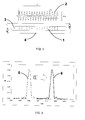
- FIG.1 is a schematic of a FBG, with a representation of its refractive index modulation.
- FIG. 2 is a representation of the reflective spectrum of a FBG, and the spectral shift promoted by a uniform longitudinal strain.
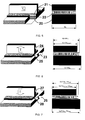
- FIG. 3 is a representational view of a monolithic composite part composed by a skin and a reinforcing and/or stiffening structure, and a detail of the part composed by a portion of skin and a part of a stiffener, that will be use as a sample to explain the operation principles of the invention
- FIG. 4 is a magnification of the sample of FIG. 3, showing integrated optical fibres in several probable positions in the part: superficially attached or embedded into the skin or the reinforcement/stiffener, internally embedded into the skin or the reinforcement/stiffener, and/or embedded into the bonding line (at any of both sides of the adhesive layer, if it is present). The geometry of the reinforcing/stiffening element represented in the sample is a typical T section, but the invention is applicable in any reinforcing/stiffening configuration (I section, J, section, U section, hat section, inverted hat section, etc.).
- FIG. 5 is the same view of FIG. 4 immediately before the start of the cu r-ing/bonding process. Skin and reinforcement/stiffener are separated parts with the geometry and dimensions correspondent to room temperature. A section shows the position of a fibre optic embedded in the interface of skin and rei nforcement/stiffener.
- FIG. 6 is the same view of FIG. 4 during the heating phase of the high temperature assembly process. The expansion coefficients of the skin, the reinforcement/stiffener and the embedded fibre optics are different and, until the vitrification of the adhesive and the resin of the un-cured parts, there is a relative movement between all the elements. Although only longitudinal effects have been represented, the phenomenon is tri-dimensional.
- FIG. 7 is the same view of FIG. 4 during the cooling phase of the high temperature assembly process. As the skin, the stiffener and the embedded fibres have consolidated at high temperature, the relative movement has become a permanent shift between all the elements, and their differential shrinkage drives to the storing of residual stresses/strains. Although only longitudinal effects have been represented, the phenomenon is tri-dimensional.
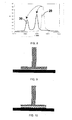
- FIG. 8 shows the evolution of the reflective of the spectrum of a fibre Bragg grating embedded in a composite part during the consolidation process. Thermal longitudinal residual stresses/strains promotes a general shift of the reflective spectrum, and transverse stresses/strains forces a splitting.
- FIG. 9 is the same view of FIG. 5, representing a de-bonding between skin and reinforcement/stiffener. In this case, a FBG embedded in the bonding line may remain bonded to the skin or separate from the skin with the de-bonded rei nforcement/stiffener.
- FIG. 10 is the same view of FIG. 4, representing a delamination of the reinforcement/stiffener. In this case, FBGs embedded in the bonding line remains bonded at the skin.
- FIG. 11 is the same view of FIG. 4, representing a delamination of the skin. In this case, FBGs embedded in the bonding line separates from the skin with the de-bonded reinforcement/stiffener.
- FIG. 12 shows a representation of the evolution of the reflective spectrum of a fibre Bragg grating embedded in a composite part promoted by uniform longitudinal residual stresses/strains released in a damage event.
- FIG. 13 shows a representation of the evolution of the reflective spectrum of a fibre Bragg grating embedded in a composite part promoted by uniform transverse residual stresses/strains released in a damage event.
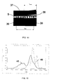
- FIG. 14 shows the section of FIG. 8 with a local damage (schematically represented as a delamination) partially affecting a FBG.
- FIG. 15 shows a representation of the evolution of the reflective spectrum of a fibre Bragg grating embedded in a composite part promoted by a non-uniform residual stresses/strains release in a damage event similar as that represented in FIG. 14.
- As represented in FIG. 1, a fibre optic Bragg grating (FBG) 1 is a
periodic pattern 2 induced in the refractive index of thecore 3 of a fibre optic 4 by means of an intense UV holographic beam. - The periodic optical structure of a FBG behaves as a very narrow optical filter with its reflective spectrum, shown as 5 in FIG. 2, centred in a wavelength given by the Bragg condition, I = 2nL, where I is the central wavelength of the spectral signal of the grating (known as Bragg wavelength), n is the average effective refractive index along the grating, and L is the pitch of the periodic structure of the grating.
- If a FBG is submitted to a uniform mechanical strain, the pitch and the refractive index of the grating changes, and the centre of the spectrum shifts to the
position 6 given by the new Bragg condition. The relation between this strain and the wavelength shift is absolutely linear. Something similar happens with thermal strain. This singular photoelastic and thermo-optical behaviour, and their low profile, allow fibre Bragg gratings (FBGs) to be used as optical strain gauges in multiple applications, even embedded as internal strain sensors in advanced composite materials. - FIG 3 represents a sample of the first operation in the implementation of the proposed invention: the integration of a network of FBGs in a sample part, a structure composed by a skin 7, that can be pre-cured or uncured, and a
stiffening structure 8, pre-cured or uncured. In order to simplify the problem, we will considerate a sub-part of the structure, consistent in a portion ofskin 9 and thecorrespondent stiffener 10. - FIG. 4 represents a frontal view of the sub-part of FIG. 3, where integrated optical fibres are shown: a fibre optic superficially bonded to the rei nforcement/stiffener 11, superficially embedded into the reinforcement/
stiffener 12, internally embedded into the reinforcement/stiffener 13, embedded into the bonding line, between the adhesive layer 14 (if adhesive is used, as adhesive is not required in co-curing processes) and the reinforcement/stiffener 15, or between the adhesive layer (if adhesive is used) and theskin 16, internally embedded into theskin 17, superficially embedded into theskin 18 or superficially bonded to theskin 19. - The structure will consolidate in a curing process, in which a temperature and pressure cycles are applied. FIG. 5 is a magnification of the sub-part of FIG. 3, at room temperature, before the heating phase of the high temperature consolidation process. Skin, reinforcement/stiffener and fibres present the dimensions correspondent to room temperature xio. A section of the subpart shows, as example, the relative position of a
fibre optic 22 embedded into the bonding line between theskin 20 and the reinforcement/stiffener 21 (results can be extended to the cases of a fibre optic superficially bonded or embedded into the skin or the reinforcement/stiffener in a previous curing cycle or during the final consolidation process). - During the heating phase of the consolidation process, shown in FIG. 6, if the stacking sequence of the skin and the reinforcement/stiffener are different, their longitudinal and transversal expansion coefficients, and the expansion coefficient of the embedded fibre are different and, during the initial part of the cycle, before the consolidation of the part, that happens at a temperature higher the than initial room temperature, the evolution of the
skin 23, reinforcement/stiffener 24 andfibre optic 25 are independent. - After this consolidation, and during the cooling phase of the process, shown in FIG. 7, the shrinkage of the part causes promotes an evolution of the longitudinal and transverse strains/stresses field around the integrated FBG that can be detected by means of a perturbation of its reflective spectrum (see sample spectra of FIG. 8), generally consistent in:
- A global wavelength shift (in FIG. 8, estimatively represented by the shift of the gravity centre of the spectrum, from 29 to 30), consequence mainly from the longitudinal strain applied to the grating.
- A spectral splitting (easily observable in FIG. 8, with a clear evolution from
spectrum 29 to spectrum 30) caused by an optical birefringence effect promoted by the thermal residual transverse stresses/strains resultant over the grating - The invention would be intended to detect the following possible modes of failure of the interface skin/(reinforcement/stiffener):
- Debonding of the reinforcement/stiffener (FIG. 9)
- Delamination of the flange of the reinforcement/stiffener (FIG. 10)
- Delamination of the skin (FIG. 11)
- In all the cases, with the part loaded in a known load case (considered as a reference load condition), at the proximity of the damage, the skin, the reinforcement/stiffener and the integrated FBGs will be submitted to a strains/stresses field different than the initial field of the undamaged structure, due to the release of the stored residual stresses/strains.
- Then, the integrated FBGs will show a perturbation in their reflective spectra reflecting this effect: a spectral shift (see FIG. 12, with an evolution from 31 to 32), correspondent to a longitudinal stresses/strains release, and/or a change in the distance between the two peaks (see FIG. 13, with an evolution from 33 to 34), correspondent to a transverse stresses/strains release. Positive detection of these effects would allow identifying the occurrence of failure of the monitored part.
- The invention would be intended also to detect the progression of the failure near the integrated FBGs. FIG. 14 shows the same detailed section of FIG. 5, with a fibre optic 35 embedded into the bonding line of the
skin 36 and the reinforcement/stiffener 37. The progression of a damage event 38 (delamination, debonding...) near theFBG sensor 39 would promote a non-uniform strain field, variable in time, and a subsequent spectral distortion (see sample spectrum of FIG. 15, with an evolution from 40 to 41). Positive detection of this effect would allow identifying the occurrence and progression of failure of the monitored part. - This invention may be embodied in other specific forms without departing from the spirit or essential characteristics thereof. The present embodiments are therefore to be considered in all respects as illustrative and not restrictive, the scope of the invention being indicated by the appended claims rather than by the foregoing description; and all changes that come within meaning and range of equivalency of the claims are therefore intended to be embraced therein.
Claims (4)
- A method of monitoring structural damage in a composite structure manufactured by co-curing, co-bonding or secondary bonding of several sub-components (7, 8), using fibre optic Bragg grating sensors attached or embedded to or between (in the bonding line) said sub-components, characterised by comprising the steps of:a) measuring the wavelength spectra (31, 33, 40) of said Bragg grating sensors at the end of the manufacturing of the part, and in a known load condition, considered as reference;b) identifying the occurrence of a failure of the structure and the progress of said failure detecting the release of the residual stresses/strains stored during the curing process by measuring changes (31 to 32, 33 to 34, 40 to 41) with respect to said reference wavelength spectra.
- A method according to claim 1, wherein a change of the wavelength spectrum (31 to 32) consisting of a shift of the intensity peaks allows the identification of a failure causing a longitudinal stress release.
- A method according to claim 1, wherein a change of the wavelength spectrum (33 to 34) consisting of a change in the distance between the intensity peaks allows the identification of a failure causing a transverse stress release.
- A method according to claim 1, wherein a change of the reflective spectrum (40 to 41) consisting of a general spectral distortion allows the detection of a failure causing a non-uniform longitudinal and/or transverse stress release.
Priority Applications (9)
| Application Number | Priority Date | Filing Date | Title |
|---|---|---|---|
| DE602004026901T DE602004026901D1 (en) | 2004-12-28 | 2004-12-28 | Process for monitoring structural damage and its progress in monolithic composite structures using fiber Bragg grating sensors |
| EP04107032A EP1677091B1 (en) | 2004-12-28 | 2004-12-28 | Method to monitor structural damage occurrence and progression in monolithic composite structures using fibre bragg grating sensors |
| ES04107032T ES2345548T3 (en) | 2004-12-28 | 2004-12-28 | APPEARANCE MONITORING PROCEDURE AND STRUCTURAL DAMAGE PROGRESSION IN MONOLITIC STRUCTURES OF COMPOSITE MATERIAL USING BRAGG DIFFACTION NETWORKS. |
| AT04107032T ATE466268T1 (en) | 2004-12-28 | 2004-12-28 | METHOD FOR MONITORING STRUCTURAL DAMAGE AND ITS PROGRESS IN MONOLITIC COMPOSITE STRUCTURES USING FIBER BRAGG GRID SENSORS |
| US11/296,855 US7283693B2 (en) | 2004-12-28 | 2005-12-07 | Method to monitor structural damage occurrence and progression in monolithic composite structures using fibre Bragg grating sensors |
| IL172470A IL172470A (en) | 2004-12-28 | 2005-12-08 | Method to monitor structural damage occurrence and progression in monolithic composite structures using fibre bragg grating sensors |
| CA002529939A CA2529939A1 (en) | 2004-12-28 | 2005-12-12 | Method to monitor structural damage occurrence and progression in monolithic composite structures using fibre bragg grating sensors |
| AU2005244556A AU2005244556B2 (en) | 2004-12-28 | 2005-12-15 | Method to monitor structural damage occurrence and progression in monolithic composite structures using fibre bragg grating sensors |
| BRPI0505640-3A BRPI0505640A (en) | 2004-12-28 | 2005-12-27 | method for monitoring the occurrence of structural damage and progression in monolithic composite structures using fiber bragg grating sensors |
Applications Claiming Priority (1)
| Application Number | Priority Date | Filing Date | Title |
|---|---|---|---|
| EP04107032A EP1677091B1 (en) | 2004-12-28 | 2004-12-28 | Method to monitor structural damage occurrence and progression in monolithic composite structures using fibre bragg grating sensors |
Publications (2)
| Publication Number | Publication Date |
|---|---|
| EP1677091A1 true EP1677091A1 (en) | 2006-07-05 |
| EP1677091B1 EP1677091B1 (en) | 2010-04-28 |
Family
ID=34930181
Family Applications (1)
| Application Number | Title | Priority Date | Filing Date |
|---|---|---|---|
| EP04107032A Expired - Lifetime EP1677091B1 (en) | 2004-12-28 | 2004-12-28 | Method to monitor structural damage occurrence and progression in monolithic composite structures using fibre bragg grating sensors |
Country Status (9)
| Country | Link |
|---|---|
| US (1) | US7283693B2 (en) |
| EP (1) | EP1677091B1 (en) |
| AT (1) | ATE466268T1 (en) |
| AU (1) | AU2005244556B2 (en) |
| BR (1) | BRPI0505640A (en) |
| CA (1) | CA2529939A1 (en) |
| DE (1) | DE602004026901D1 (en) |
| ES (1) | ES2345548T3 (en) |
| IL (1) | IL172470A (en) |
Cited By (5)
| Publication number | Priority date | Publication date | Assignee | Title |
|---|---|---|---|---|
| WO2012003836A1 (en) * | 2010-07-08 | 2012-01-12 | Vestas Wind Systems A/S | Turbine blade temperature measurement system and method of manufacture of turbine blades |
| US8235326B2 (en) | 2007-07-26 | 2012-08-07 | Airbus Operations Limited | Aircraft landing gear load sensor |
| US8616501B2 (en) | 2008-12-17 | 2013-12-31 | Airbus Operations Gmbh | Pre-installed adaptable supply network for aeroplanes |
| EP3431934A4 (en) * | 2016-04-18 | 2019-03-27 | Mitsubishi Heavy Industries, Ltd. | SEPARATION DETECTION METHOD AND SEPARATION DETECTION DEVICE |
| DE102012109252B4 (en) * | 2011-09-29 | 2021-01-07 | General Electric Company | Wind turbine blade edge monitoring system |
Families Citing this family (14)
| Publication number | Priority date | Publication date | Assignee | Title |
|---|---|---|---|---|
| JP5208759B2 (en) * | 2005-11-30 | 2013-06-12 | エアバス オペレーションズ、ソシエダ リミタダ | Composite structure embedded with optical fiber and repair method thereof |
| US7623974B2 (en) * | 2007-01-30 | 2009-11-24 | Pratt & Whitney Rocketdyne, Inc. | System and method for detecting onset of structural failure |
| US20100001874A1 (en) * | 2008-07-01 | 2010-01-07 | Pratt & Whitney Rocketdyne, Inc. | Remote transmission system and method for detecting onset of structural failure |
| US20130050685A1 (en) * | 2011-08-23 | 2013-02-28 | The Boeing Company | Composite structure having an embedded sensing system |
| US9170172B2 (en) | 2011-08-23 | 2015-10-27 | The Boeing Company | Composite structure having an embedded sensing system |
| FR2998662B1 (en) * | 2012-11-23 | 2019-10-25 | Airbus Operations | DEVICE FOR DEFORMATION MEASUREMENT AND IMPLANTATION OF SUCH A DEVICE IN AN ELEMENT |
| IL247408B (en) | 2016-08-21 | 2018-03-29 | Elbit Systems Ltd | System and method for detecting weakening of the adhesion strength between structural elements |
| WO2018232136A1 (en) | 2017-06-16 | 2018-12-20 | Saint-Gobain Adfors Canada, Ltd. | Sensing textile |
| CN107991060B (en) * | 2017-11-20 | 2019-08-20 | 南京航空航天大学 | Based on adaptive and iterative algorithm load distribution type fiber-optic discrimination method |
| CN111174934B (en) * | 2020-01-08 | 2022-10-11 | 兰州大学 | Optical fiber monitoring method for interface damage degradation process of composite structure |
| CN114061474B (en) * | 2021-11-15 | 2023-02-28 | 山东大学 | Low-speed impact positioning method for composite material structure of implanted fiber grating sensor |
| TR2024002380A2 (en) * | 2024-02-28 | 2025-09-22 | Tusas Tuerk Havacilik Ve Uzay Sanayii Anonim Sirketi | A Composite Structure with Structural Health Monitoring Sensors |
| CN118549279B (en) * | 2024-07-25 | 2024-10-29 | 南京航空航天大学 | Composite material layer plate damage tomography method based on optical fiber frequency band energy attenuation characteristics |
| CN119534454B (en) * | 2024-10-24 | 2025-09-26 | 武汉理工大学 | Composite material internal damage judging system and method based on interlayer sensing data |
Citations (1)
| Publication number | Priority date | Publication date | Assignee | Title |
|---|---|---|---|---|
| WO1998010242A1 (en) * | 1996-09-09 | 1998-03-12 | Eric Udd | Fiber optic grating transverse strain sensor system |
Family Cites Families (1)
| Publication number | Priority date | Publication date | Assignee | Title |
|---|---|---|---|---|
| DE10214984B4 (en) * | 2002-04-04 | 2006-01-19 | Eads Deutschland Gmbh | Actuator and sensor system for composite structures |
-
2004
- 2004-12-28 EP EP04107032A patent/EP1677091B1/en not_active Expired - Lifetime
- 2004-12-28 DE DE602004026901T patent/DE602004026901D1/en not_active Expired - Lifetime
- 2004-12-28 AT AT04107032T patent/ATE466268T1/en not_active IP Right Cessation
- 2004-12-28 ES ES04107032T patent/ES2345548T3/en not_active Expired - Lifetime
-
2005
- 2005-12-07 US US11/296,855 patent/US7283693B2/en not_active Expired - Lifetime
- 2005-12-08 IL IL172470A patent/IL172470A/en not_active IP Right Cessation
- 2005-12-12 CA CA002529939A patent/CA2529939A1/en not_active Abandoned
- 2005-12-15 AU AU2005244556A patent/AU2005244556B2/en not_active Ceased
- 2005-12-27 BR BRPI0505640-3A patent/BRPI0505640A/en not_active IP Right Cessation
Patent Citations (1)
| Publication number | Priority date | Publication date | Assignee | Title |
|---|---|---|---|---|
| WO1998010242A1 (en) * | 1996-09-09 | 1998-03-12 | Eric Udd | Fiber optic grating transverse strain sensor system |
Non-Patent Citations (2)
| Title |
|---|
| LENG J ET AL: "Structural health monitoring of smart composite materials by using EFPI and FBG sensors", SENSORS AND ACTUATORS A, ELSEVIER SEQUOIA S.A., LAUSANNE, CH, vol. 103, no. 3, 15 February 2003 (2003-02-15), pages 330 - 340, XP004406056, ISSN: 0924-4247 * |
| OKABE Y ET AL: "DETECTION OF TRANSVERSE CRACKS IN CFRP COMPOSITES USING EMBEDDED FIBER BRAGG GRATING SENSORS", SMART MATERIALS AND STRUCTURES, IOP PUBLISHING LTD., BRISTOL, GB, vol. 9, no. 6, December 2000 (2000-12-01), pages 832 - 838, XP000977388, ISSN: 0964-1726 * |
Cited By (10)
| Publication number | Priority date | Publication date | Assignee | Title |
|---|---|---|---|---|
| US8235326B2 (en) | 2007-07-26 | 2012-08-07 | Airbus Operations Limited | Aircraft landing gear load sensor |
| US8616501B2 (en) | 2008-12-17 | 2013-12-31 | Airbus Operations Gmbh | Pre-installed adaptable supply network for aeroplanes |
| WO2012003836A1 (en) * | 2010-07-08 | 2012-01-12 | Vestas Wind Systems A/S | Turbine blade temperature measurement system and method of manufacture of turbine blades |
| CN103097115A (en) * | 2010-07-08 | 2013-05-08 | 维斯塔斯风力系统有限公司 | Turbine blade temperature measurement system and method of manufacture of turbine blades |
| US20130170991A1 (en) * | 2010-07-08 | 2013-07-04 | Vestas Wind Systems A/S | Turbine blade temperature measurement system and method of manufacture of turbine blades |
| CN103097115B (en) * | 2010-07-08 | 2015-09-16 | 维斯塔斯风力系统有限公司 | The manufacture method of wind turbine blade temperature measurement system and wind turbine blade |
| US9566754B2 (en) | 2010-07-08 | 2017-02-14 | Vesta Wind Systems A/S | Turbine blade temperature measurement system and method of manufacture of turbine blades |
| DE102012109252B4 (en) * | 2011-09-29 | 2021-01-07 | General Electric Company | Wind turbine blade edge monitoring system |
| EP3431934A4 (en) * | 2016-04-18 | 2019-03-27 | Mitsubishi Heavy Industries, Ltd. | SEPARATION DETECTION METHOD AND SEPARATION DETECTION DEVICE |
| US10809051B2 (en) | 2016-04-18 | 2020-10-20 | Mitsubishi Heavy Industries, Ltd. | Debonding detecting method and debonding detecting device |
Also Published As
| Publication number | Publication date |
|---|---|
| ES2345548T3 (en) | 2010-09-27 |
| ATE466268T1 (en) | 2010-05-15 |
| EP1677091B1 (en) | 2010-04-28 |
| US20060140532A1 (en) | 2006-06-29 |
| BRPI0505640A (en) | 2006-09-19 |
| CA2529939A1 (en) | 2006-06-28 |
| AU2005244556B2 (en) | 2011-05-26 |
| IL172470A (en) | 2010-11-30 |
| AU2005244556A1 (en) | 2006-07-13 |
| IL172470A0 (en) | 2006-04-10 |
| US7283693B2 (en) | 2007-10-16 |
| DE602004026901D1 (en) | 2010-06-10 |
Similar Documents
| Publication | Publication Date | Title |
|---|---|---|
| EP1677091B1 (en) | Method to monitor structural damage occurrence and progression in monolithic composite structures using fibre bragg grating sensors | |
| Ferdinand et al. | Applications of fiber Bragg grating sensors in the composite industry | |
| Ruzek et al. | Monitoring of compressive behaviour of stiffened composite panels using embedded fibre optic and strain gauge sensors | |
| AU2023358088A1 (en) | Method for monitoring structural elements in composite | |
| WO2009126991A1 (en) | Method and system for monitoring strain in a structure using an optical fibre | |
| Milanoski et al. | A strain-based health indicator for the SHM of skin-to-stringer disbond growth of composite stiffened panels in fatigue | |
| Davis et al. | In-situ health monitoring of bonded composite repairs using a novel fiber Bragg grating sensing arrangement | |
| Fernández-López et al. | Damage detection in a stiffened curved plate by measuring differential strains | |
| Yan et al. | Fatigue life measuring system using fiber optic sensors for CFRP pantograph upper arm | |
| Schilder et al. | Structural health monitoring of composite structures by distributed fibre optic sensors | |
| Ramakrishnan et al. | 17 Optical Fiber Sensors for Smart Composite Materials and Structures | |
| RU2786976C1 (en) | Method for controlling the design of a pressure cylinder made of a polymer composite material with a metal liner and a device for its implementation | |
| Mulle et al. | Instrumented technological specimen (ITS): curing process and mechanical characterization using embedded fiber Bragg gratings | |
| Karagiannis et al. | Monitoring of aeronautical composites with embedded FOBG sensor: Part I—Manufacturing and strain response under incremental fatigue loading spectrum | |
| RU2793297C1 (en) | Method for opto-thermal control of internal deformations of a structure made of a polymer composite material and a device for its implementation | |
| RU2850632C1 (en) | Method for controlling deformations of composite materials based on fibre bragg grids | |
| RU2793298C1 (en) | Method for non-destructive quality control of the design and resource of an automotive gas cylinder made of polymer composite materials and a device for its implementation | |
| Guemes | SHM of Composite structures by fiber optic sensors | |
| Loman et al. | Fatigue Detection on Glass Fibre Reinforced Polymer Material Using Fiber Bragg Grating Sensor | |
| Janetzko-Preisler et al. | Integration and evaluation of a meander-shaped fibre-optical sensor in a GFRP leaf spring | |
| Kulpa et al. | Experimental verification of FRP bridge deck's monitoring system based on DFOS sensors | |
| Atli-Veltin et al. | Experimental demonstration of health monitoring of composites using FBG sensor arrays | |
| Sepe | Structural Health Monitoring of Composite Materials with Optical Fibres under Fatigue Loading | |
| Menendez et al. | Damage detection in composite materials by FBGs | |
| Mohammadkarimi et al. | Embedding Fiber Segment Interferometry for Localization of Defects in Composite Structures |
Legal Events
| Date | Code | Title | Description |
|---|---|---|---|
| PUAI | Public reference made under article 153(3) epc to a published international application that has entered the european phase |
Free format text: ORIGINAL CODE: 0009012 |
|
| AK | Designated contracting states |
Kind code of ref document: A1 Designated state(s): AT BE BG CH CY CZ DE DK EE ES FI FR GB GR HU IE IS IT LI LT LU MC NL PL PT RO SE SI SK TR |
|
| AX | Request for extension of the european patent |
Extension state: AL BA HR LV MK YU |
|
| 17P | Request for examination filed |
Effective date: 20060622 |
|
| AKX | Designation fees paid |
Designated state(s): AT BE BG CH CY CZ DE DK EE ES FI FR GB GR HU IE IS IT LI LT LU MC NL PL PT RO SE SI SK TR |
|
| GRAP | Despatch of communication of intention to grant a patent |
Free format text: ORIGINAL CODE: EPIDOSNIGR1 |
|
| GRAS | Grant fee paid |
Free format text: ORIGINAL CODE: EPIDOSNIGR3 |
|
| GRAA | (expected) grant |
Free format text: ORIGINAL CODE: 0009210 |
|
| AK | Designated contracting states |
Kind code of ref document: B1 Designated state(s): AT BE BG CH CY CZ DE DK EE ES FI FR GB GR HU IE IS IT LI LT LU MC NL PL PT RO SE SI SK TR |
|
| REG | Reference to a national code |
Ref country code: GB Ref legal event code: FG4D |
|
| REG | Reference to a national code |
Ref country code: CH Ref legal event code: EP |
|
| REG | Reference to a national code |
Ref country code: IE Ref legal event code: FG4D |
|
| REF | Corresponds to: |
Ref document number: 602004026901 Country of ref document: DE Date of ref document: 20100610 Kind code of ref document: P |
|
| REG | Reference to a national code |
Ref country code: NL Ref legal event code: VDEP Effective date: 20100428 |
|
| RAP2 | Party data changed (patent owner data changed or rights of a patent transferred) |
Owner name: AIRBUS OPERATIONS, S.L. |
|
| LTIE | Lt: invalidation of european patent or patent extension |
Effective date: 20100428 |
|
| REG | Reference to a national code |
Ref country code: ES Ref legal event code: FG2A Ref document number: 2345548 Country of ref document: ES Kind code of ref document: T3 |
|
| PG25 | Lapsed in a contracting state [announced via postgrant information from national office to epo] |
Ref country code: LT Free format text: LAPSE BECAUSE OF FAILURE TO SUBMIT A TRANSLATION OF THE DESCRIPTION OR TO PAY THE FEE WITHIN THE PRESCRIBED TIME-LIMIT Effective date: 20100428 Ref country code: SE Free format text: LAPSE BECAUSE OF FAILURE TO SUBMIT A TRANSLATION OF THE DESCRIPTION OR TO PAY THE FEE WITHIN THE PRESCRIBED TIME-LIMIT Effective date: 20100428 Ref country code: NL Free format text: LAPSE BECAUSE OF FAILURE TO SUBMIT A TRANSLATION OF THE DESCRIPTION OR TO PAY THE FEE WITHIN THE PRESCRIBED TIME-LIMIT Effective date: 20100428 |
|
| PG25 | Lapsed in a contracting state [announced via postgrant information from national office to epo] |
Ref country code: SI Free format text: LAPSE BECAUSE OF FAILURE TO SUBMIT A TRANSLATION OF THE DESCRIPTION OR TO PAY THE FEE WITHIN THE PRESCRIBED TIME-LIMIT Effective date: 20100428 Ref country code: IS Free format text: LAPSE BECAUSE OF FAILURE TO SUBMIT A TRANSLATION OF THE DESCRIPTION OR TO PAY THE FEE WITHIN THE PRESCRIBED TIME-LIMIT Effective date: 20100828 Ref country code: FI Free format text: LAPSE BECAUSE OF FAILURE TO SUBMIT A TRANSLATION OF THE DESCRIPTION OR TO PAY THE FEE WITHIN THE PRESCRIBED TIME-LIMIT Effective date: 20100428 Ref country code: AT Free format text: LAPSE BECAUSE OF FAILURE TO SUBMIT A TRANSLATION OF THE DESCRIPTION OR TO PAY THE FEE WITHIN THE PRESCRIBED TIME-LIMIT Effective date: 20100428 |
|
| PG25 | Lapsed in a contracting state [announced via postgrant information from national office to epo] |
Ref country code: PL Free format text: LAPSE BECAUSE OF FAILURE TO SUBMIT A TRANSLATION OF THE DESCRIPTION OR TO PAY THE FEE WITHIN THE PRESCRIBED TIME-LIMIT Effective date: 20100428 Ref country code: CY Free format text: LAPSE BECAUSE OF FAILURE TO SUBMIT A TRANSLATION OF THE DESCRIPTION OR TO PAY THE FEE WITHIN THE PRESCRIBED TIME-LIMIT Effective date: 20100428 |
|
| PG25 | Lapsed in a contracting state [announced via postgrant information from national office to epo] |
Ref country code: DK Free format text: LAPSE BECAUSE OF FAILURE TO SUBMIT A TRANSLATION OF THE DESCRIPTION OR TO PAY THE FEE WITHIN THE PRESCRIBED TIME-LIMIT Effective date: 20100428 Ref country code: PT Free format text: LAPSE BECAUSE OF FAILURE TO SUBMIT A TRANSLATION OF THE DESCRIPTION OR TO PAY THE FEE WITHIN THE PRESCRIBED TIME-LIMIT Effective date: 20100830 Ref country code: EE Free format text: LAPSE BECAUSE OF FAILURE TO SUBMIT A TRANSLATION OF THE DESCRIPTION OR TO PAY THE FEE WITHIN THE PRESCRIBED TIME-LIMIT Effective date: 20100428 |
|
| PG25 | Lapsed in a contracting state [announced via postgrant information from national office to epo] |
Ref country code: RO Free format text: LAPSE BECAUSE OF FAILURE TO SUBMIT A TRANSLATION OF THE DESCRIPTION OR TO PAY THE FEE WITHIN THE PRESCRIBED TIME-LIMIT Effective date: 20100428 Ref country code: CZ Free format text: LAPSE BECAUSE OF FAILURE TO SUBMIT A TRANSLATION OF THE DESCRIPTION OR TO PAY THE FEE WITHIN THE PRESCRIBED TIME-LIMIT Effective date: 20100428 Ref country code: BE Free format text: LAPSE BECAUSE OF FAILURE TO SUBMIT A TRANSLATION OF THE DESCRIPTION OR TO PAY THE FEE WITHIN THE PRESCRIBED TIME-LIMIT Effective date: 20100428 Ref country code: SK Free format text: LAPSE BECAUSE OF FAILURE TO SUBMIT A TRANSLATION OF THE DESCRIPTION OR TO PAY THE FEE WITHIN THE PRESCRIBED TIME-LIMIT Effective date: 20100428 |
|
| PLBE | No opposition filed within time limit |
Free format text: ORIGINAL CODE: 0009261 |
|
| STAA | Information on the status of an ep patent application or granted ep patent |
Free format text: STATUS: NO OPPOSITION FILED WITHIN TIME LIMIT |
|
| 26N | No opposition filed |
Effective date: 20110131 |
|
| PG25 | Lapsed in a contracting state [announced via postgrant information from national office to epo] |
Ref country code: MC Free format text: LAPSE BECAUSE OF NON-PAYMENT OF DUE FEES Effective date: 20101231 |
|
| REG | Reference to a national code |
Ref country code: CH Ref legal event code: PL |
|
| PG25 | Lapsed in a contracting state [announced via postgrant information from national office to epo] |
Ref country code: CH Free format text: LAPSE BECAUSE OF NON-PAYMENT OF DUE FEES Effective date: 20101231 Ref country code: LI Free format text: LAPSE BECAUSE OF NON-PAYMENT OF DUE FEES Effective date: 20101231 Ref country code: IE Free format text: LAPSE BECAUSE OF NON-PAYMENT OF DUE FEES Effective date: 20101228 |
|
| PG25 | Lapsed in a contracting state [announced via postgrant information from national office to epo] |
Ref country code: HU Free format text: LAPSE BECAUSE OF FAILURE TO SUBMIT A TRANSLATION OF THE DESCRIPTION OR TO PAY THE FEE WITHIN THE PRESCRIBED TIME-LIMIT Effective date: 20101029 Ref country code: BG Free format text: LAPSE BECAUSE OF FAILURE TO SUBMIT A TRANSLATION OF THE DESCRIPTION OR TO PAY THE FEE WITHIN THE PRESCRIBED TIME-LIMIT Effective date: 20100428 Ref country code: LU Free format text: LAPSE BECAUSE OF NON-PAYMENT OF DUE FEES Effective date: 20101228 |
|
| PG25 | Lapsed in a contracting state [announced via postgrant information from national office to epo] |
Ref country code: TR Free format text: LAPSE BECAUSE OF FAILURE TO SUBMIT A TRANSLATION OF THE DESCRIPTION OR TO PAY THE FEE WITHIN THE PRESCRIBED TIME-LIMIT Effective date: 20100428 |
|
| PG25 | Lapsed in a contracting state [announced via postgrant information from national office to epo] |
Ref country code: BG Free format text: LAPSE BECAUSE OF FAILURE TO SUBMIT A TRANSLATION OF THE DESCRIPTION OR TO PAY THE FEE WITHIN THE PRESCRIBED TIME-LIMIT Effective date: 20100728 |
|
| PG25 | Lapsed in a contracting state [announced via postgrant information from national office to epo] |
Ref country code: GR Free format text: LAPSE BECAUSE OF FAILURE TO SUBMIT A TRANSLATION OF THE DESCRIPTION OR TO PAY THE FEE WITHIN THE PRESCRIBED TIME-LIMIT Effective date: 20100428 |
|
| REG | Reference to a national code |
Ref country code: FR Ref legal event code: PLFP Year of fee payment: 12 |
|
| REG | Reference to a national code |
Ref country code: FR Ref legal event code: PLFP Year of fee payment: 13 |
|
| REG | Reference to a national code |
Ref country code: FR Ref legal event code: PLFP Year of fee payment: 14 |
|
| PGFP | Annual fee paid to national office [announced via postgrant information from national office to epo] |
Ref country code: DE Payment date: 20181210 Year of fee payment: 15 |
|
| PGFP | Annual fee paid to national office [announced via postgrant information from national office to epo] |
Ref country code: GB Payment date: 20181218 Year of fee payment: 15 Ref country code: FR Payment date: 20181220 Year of fee payment: 15 |
|
| PGFP | Annual fee paid to national office [announced via postgrant information from national office to epo] |
Ref country code: ES Payment date: 20190124 Year of fee payment: 15 Ref country code: IT Payment date: 20181220 Year of fee payment: 15 |
|
| REG | Reference to a national code |
Ref country code: DE Ref legal event code: R119 Ref document number: 602004026901 Country of ref document: DE |
|
| GBPC | Gb: european patent ceased through non-payment of renewal fee |
Effective date: 20191228 |
|
| PG25 | Lapsed in a contracting state [announced via postgrant information from national office to epo] |
Ref country code: IT Free format text: LAPSE BECAUSE OF NON-PAYMENT OF DUE FEES Effective date: 20191228 Ref country code: DE Free format text: LAPSE BECAUSE OF NON-PAYMENT OF DUE FEES Effective date: 20200701 Ref country code: GB Free format text: LAPSE BECAUSE OF NON-PAYMENT OF DUE FEES Effective date: 20191228 Ref country code: FR Free format text: LAPSE BECAUSE OF NON-PAYMENT OF DUE FEES Effective date: 20191231 |
|
| REG | Reference to a national code |
Ref country code: ES Ref legal event code: FD2A Effective date: 20210524 |
|
| PG25 | Lapsed in a contracting state [announced via postgrant information from national office to epo] |
Ref country code: ES Free format text: LAPSE BECAUSE OF NON-PAYMENT OF DUE FEES Effective date: 20191229 |