EP1676723A1 - Pneumatic tire with lateral shoulder grooves - Google Patents
Pneumatic tire with lateral shoulder grooves Download PDFInfo
- Publication number
- EP1676723A1 EP1676723A1 EP05112460A EP05112460A EP1676723A1 EP 1676723 A1 EP1676723 A1 EP 1676723A1 EP 05112460 A EP05112460 A EP 05112460A EP 05112460 A EP05112460 A EP 05112460A EP 1676723 A1 EP1676723 A1 EP 1676723A1
- Authority
- EP
- European Patent Office
- Prior art keywords
- lateral grooves
- tire
- shoulder
- pneumatic tire
- groove
- Prior art date
- Legal status (The legal status is an assumption and is not a legal conclusion. Google has not performed a legal analysis and makes no representation as to the accuracy of the status listed.)
- Withdrawn
Links
- 229920001971 elastomer Polymers 0.000 claims description 12
- 239000005060 rubber Substances 0.000 claims description 11
- 238000010276 construction Methods 0.000 description 5
- 230000020169 heat generation Effects 0.000 description 5
- 230000001154 acute effect Effects 0.000 description 4
- 239000011324 bead Substances 0.000 description 4
- 230000001788 irregular Effects 0.000 description 4
- 239000000463 material Substances 0.000 description 3
- IJGRMHOSHXDMSA-UHFFFAOYSA-N Atomic nitrogen Chemical compound N#N IJGRMHOSHXDMSA-UHFFFAOYSA-N 0.000 description 2
- 150000001875 compounds Chemical class 0.000 description 2
- 230000007812 deficiency Effects 0.000 description 2
- 239000013536 elastomeric material Substances 0.000 description 2
- 239000007789 gas Substances 0.000 description 2
- 229920003052 natural elastomer Polymers 0.000 description 2
- 229920001194 natural rubber Polymers 0.000 description 2
- 229920003051 synthetic elastomer Polymers 0.000 description 2
- 239000005061 synthetic rubber Substances 0.000 description 2
- 239000011800 void material Substances 0.000 description 2
- 239000004952 Polyamide Substances 0.000 description 1
- 229910000831 Steel Inorganic materials 0.000 description 1
- 238000002679 ablation Methods 0.000 description 1
- 239000004760 aramid Substances 0.000 description 1
- 229920003235 aromatic polyamide Polymers 0.000 description 1
- 230000015572 biosynthetic process Effects 0.000 description 1
- 239000002131 composite material Substances 0.000 description 1
- 230000002950 deficient Effects 0.000 description 1
- 230000001419 dependent effect Effects 0.000 description 1
- 230000000694 effects Effects 0.000 description 1
- 239000000806 elastomer Substances 0.000 description 1
- 239000011152 fibreglass Substances 0.000 description 1
- 239000012530 fluid Substances 0.000 description 1
- 229920005555 halobutyl Polymers 0.000 description 1
- 125000004968 halobutyl group Chemical group 0.000 description 1
- 239000002184 metal Substances 0.000 description 1
- 239000000203 mixture Substances 0.000 description 1
- 229910052757 nitrogen Inorganic materials 0.000 description 1
- 229920002647 polyamide Polymers 0.000 description 1
- 238000007789 sealing Methods 0.000 description 1
- 239000007787 solid Substances 0.000 description 1
- 239000010959 steel Substances 0.000 description 1
- 239000004636 vulcanized rubber Substances 0.000 description 1
Images



Classifications
-
- B—PERFORMING OPERATIONS; TRANSPORTING
- B60—VEHICLES IN GENERAL
- B60C—VEHICLE TYRES; TYRE INFLATION; TYRE CHANGING; CONNECTING VALVES TO INFLATABLE ELASTIC BODIES IN GENERAL; DEVICES OR ARRANGEMENTS RELATED TO TYRES
- B60C11/00—Tyre tread bands; Tread patterns; Anti-skid inserts
- B60C11/03—Tread patterns
- B60C11/04—Tread patterns in which the raised area of the pattern consists only of continuous circumferential ribs, e.g. zig-zag
-
- B—PERFORMING OPERATIONS; TRANSPORTING
- B60—VEHICLES IN GENERAL
- B60C—VEHICLE TYRES; TYRE INFLATION; TYRE CHANGING; CONNECTING VALVES TO INFLATABLE ELASTIC BODIES IN GENERAL; DEVICES OR ARRANGEMENTS RELATED TO TYRES
- B60C11/00—Tyre tread bands; Tread patterns; Anti-skid inserts
- B60C11/01—Shape of the shoulders between tread and sidewall, e.g. rounded, stepped or cantilevered
-
- B—PERFORMING OPERATIONS; TRANSPORTING
- B60—VEHICLES IN GENERAL
- B60C—VEHICLE TYRES; TYRE INFLATION; TYRE CHANGING; CONNECTING VALVES TO INFLATABLE ELASTIC BODIES IN GENERAL; DEVICES OR ARRANGEMENTS RELATED TO TYRES
- B60C11/00—Tyre tread bands; Tread patterns; Anti-skid inserts
- B60C11/03—Tread patterns
- B60C11/0306—Patterns comprising block rows or discontinuous ribs
-
- B—PERFORMING OPERATIONS; TRANSPORTING
- B60—VEHICLES IN GENERAL
- B60C—VEHICLE TYRES; TYRE INFLATION; TYRE CHANGING; CONNECTING VALVES TO INFLATABLE ELASTIC BODIES IN GENERAL; DEVICES OR ARRANGEMENTS RELATED TO TYRES
- B60C11/00—Tyre tread bands; Tread patterns; Anti-skid inserts
- B60C11/03—Tread patterns
- B60C11/0327—Tread patterns characterised by special properties of the tread pattern
- B60C11/033—Tread patterns characterised by special properties of the tread pattern by the void or net-to-gross ratios of the patterns
-
- Y—GENERAL TAGGING OF NEW TECHNOLOGICAL DEVELOPMENTS; GENERAL TAGGING OF CROSS-SECTIONAL TECHNOLOGIES SPANNING OVER SEVERAL SECTIONS OF THE IPC; TECHNICAL SUBJECTS COVERED BY FORMER USPC CROSS-REFERENCE ART COLLECTIONS [XRACs] AND DIGESTS
- Y10—TECHNICAL SUBJECTS COVERED BY FORMER USPC
- Y10S—TECHNICAL SUBJECTS COVERED BY FORMER USPC CROSS-REFERENCE ART COLLECTIONS [XRACs] AND DIGESTS
- Y10S152/00—Resilient tires and wheels
- Y10S152/901—Tread pattern having no blocks and having circumferential ribs defined by linear circumferential grooves having straight edges
Definitions
- the present invention generally relates to pneumatic tires and, more particularly, to a pneumatic tire characterized by lateral grooves in the shoulder rib.
- Tires typically include a tread with a tread pattern that, when the tire is loaded, defines a footprint providing a frictional engagement with the road.
- Various tire constructions have been used to provide sufficient contact pressure at the shoulder during tire life while combating irregular wear and limiting heat generation in early life. However, these constructions have proven to be deficient in one regard or another.
- One approach is to provide the shoulder rib with a step-off in which the whole shoulder rib is lowered relative to central tread regions. This construction, however, initiates irregular wear at an early mileage.
- Another approach is to use different types of decoupling grooves. Vertical decoupling grooves, which define a sacrificial shoulder rib, are prone to tearing that can propagate and result in shoulder rib tear. Side decoupling grooves are unproven and remain intact for most of the tire life, risking problems of fatigue at the deepest, rounded part. Dense shoulder blading is expensive, more so than molded grooves. Because shoulder blading is generally deep, it also increases the likelihood of crack formation.
- the invention relates to a pneumatic tire according to claim 1.
- the tire of the present invention combines sufficient contact pressure at the shoulder during tire life to counteract irregular wear and to limit heat generation in early life. This is an especially acute problem with Very Low Aspect Ratio (VLAR) tires.
- VLAR Very Low Aspect Ratio
- all tires are impacted to some degree because nonskid depth (NSK) and/or heat generation are increased (to maximize treadwear potential (NSK) and as a side effect of increased wear resistance).
- Circumferential means circular lines or directions extending along the surface of the sidewall perpendicular to the axial direction.
- Equatorial plane means the plane perpendicular to the tire's axis of rotation and passing through the center of its tread.
- “Footprint” means the contact patch or area of contact of the tire tread with a flat surface at zero speed and under design load and pressure.
- “Groove” means an elongated void area in a tread that may extend circumferentially or laterally about the tread in a straight, curved, or zig-zag manner. Grooves ordinarily remain open in the tire footprint.
- “Lateral” means a direction parallel to the axial direction, as in across the width of the tread or crown region.
- “Lateral edge” means the axially outermost edge of the tread as defined by a plane parallel to the equatorial plane and intersecting the outer ends of the axially outermost traction lugs at the radial height of the inner tread surface.
- Leading refers to a portion or part of the tread that contacts the ground first, with respect to a series of such parts or portions, during rotation of the tire in the direction of travel.
- Nonskid means depth of grooves in a tire tread.
- Ring and radially mean directions radially toward or away from the axis of rotation of the tire.
- Ring means a circumferentially extending strip of rubber on the tread which is defined by at least one circumferential groove.
- Shader means the upper portion of sidewall just below the tread edge.
- “Sidewall” means that portion of a tire between the tread and the bead area.
- Sipes refer to small slots molded into ribs of a tire that subdivide the tread surface and improve traction characteristics. Sipes tend to close completely in a tire footprint and constitute very narrow slots or slits formed by thin metal strips placed in the tire mold, referred to as sipe blades.
- Thread means a molded rubber component which, when bonded to a tire casing, includes that portion of the tire that comes into contact with the road when the tire is normally inflated and under normal load.
- Thread width means the arc length of the road contacting tread surface in the axial direction, that is, in a plane parallel to the axis of rotation of the tire.
- Tread Arc Width means the width of an arc having its center located on the equatorial plane (EP) and which substantially coincides with the radially outermost surfaces of the various traction elements (i.e., lugs, blocks, buttons, ribs, etc.) across the lateral or axial width of the tread portions of a tire (i.e., between the lateral edges of the tread) when the tire is mounted upon its designated rim and inflated to its specified inflation pressure but not subject to any load.
- traction elements i.e., lugs, blocks, buttons, ribs, etc.
- a pneumatic tire 10 of the present invention includes a road-contacting tread 12 extending between lateral edges 14, 16, a pair of sidewalls 18 extending from the lateral edges 14, 16, respectively, a shoulder 20 defined at the juncture between each sidewall 18 and tread 12, and a carcass 22 defining a support structure for tire 10.
- the tread 12 and sidewalls 18 are comprised of a suitable material, such as a natural or synthetic rubber compound, selected in accordance with engineering standards accepted in the tire art.
- Tire 10 may have mirror symmetry for reflection about a mid-circumferential or equatorial plane 25 bisecting tire 10 midway between lateral edges 14, 16.
- the tire 10 includes an axis of rotation 11 that orthogonally intersects the equatorial plane 25.
- the carcass 22 includes a pair of beads 24 each having an annular inextensible tensile member 26 and an apex 28. Each of the sidewalls 18 is terminated by a corresponding one of the beads 24, which provide support for the tire 10 and aid in sealing air in the tire 10.
- the carcass 22 further includes at least one composite ply structure 30 having opposite turn-up ply ends 32 each wrapped about one of the beads 24.
- Tire 10 further includes a belt package 34 typically characterized by a plurality of individual cut belt plies and/or spiral wound belt layers. The construction of the belt package 34 varies according to the tire construction.
- the plies of the ply structure 30 and the belt package 34 generally consist of cord reinforced elastomeric material in which the cords may be aramid, steel, fiberglass or polyamide and the elastomer is a vulcanized rubber material.
- the cord reinforced elastomeric material constituting the ply structure 30 and belt package 34 are encased in and bonded to a suitable material, such as a natural or synthetic rubber compound, selected in accordance with engineering standards accepted in the tire art.
- a set of tires 10 is placed on a vehicle, such as an automobile.
- the tread 12 protects the carcass 22 and belt package 34 while providing traction for the tire 10 on the road surface.
- Tire 10 contains an inflation fluid, like nitrogen, air, or another gas or gas mixture, that sustains the vehicle load.
- a liner 35 which may be formed of, for example, halobutyl rubber, defines an air impervious chamber for containing the air pressure when the tire 10 is inflated.
- the tread 12 is partitioned by a plurality of continuous parallel circumferential grooves 36 into a plurality of ribs 38, 40, 42, 44, 46 that extend circumferentially about the tire 10.
- Any or all of the ribs 38, 40, 42, 44, 46 may further include additional lateral grooves (not shown) of a groove depth commensurate with the groove depth of the circumferential grooves 36 and that communicate with and intersect the circumferential grooves 36.
- the circumferential grooves 36 and the lateral grooves define a relief pattern in any or all of the ribs 38, 40, 42, 44, 46 consisting of lugs or blocks.
- the lateral grooves 50 may have a void-to-rubber ratio of around 50 percent, such a 45 to 55 percent, which is significantly greater than the void-to-rubber ratio of conventional sipes.
- the void-to-rubber ratio is evaluated across the axial dimension of the lateral grooves 50 and takes into account the rubber contained in the transversal ribs 52, which extend axially from a shoulder edge 54 to the termination of the lateral grooves 50.
- the void portion is equal to the volume of the lateral grooves 50 and the rubber portion is equal to the volume of the transversal ribs 52.
- Sipes have a significantly lesser circumferential width and close completely in a tire footprint. In other words, the walls of the sipe contact with each other in the tire footprint, whereas the walls of the lateral grooves 50 do not contact in the tire footprint.
- Conventional sipes have a width less than 4 mm, which provides a void-to-rubber ratio for sipes that is significantly less than 50 percent.
- the lateral grooves 50 have a depth ranging from 2 mm to 25 percent to 35 percent of the non-skid depth of circumferential grooves 36 and have a width between the groove walls greater than 4 mm.
- each of the lateral grooves 50 may not be uniform across the rib 38 or 46 and will generally, if non-uniform, increase toward the shoulder edge 54 defined at the intersection between tread 12 and shoulder 20, especially in the case of a very wide Tread Arc Width (TAW).
- TSW Tread Arc Width
- the maximum width of the resulting transversal ribs 52 may be equal to the depth of the lateral grooves 50.
- the lateral grooves 50 include a single transverse groove segment having a groove depth less than the depth of circumferential grooves 36.
- the lateral grooves 50 extend axially only across a portion of the shoulder rib 46 and do not extend across the full axial dimension of the shoulder rib 46. Consequently, the lateral grooves 50 do not intersect nor communicate with the adjacent circumferential groove 36.
- the lateral grooves 50 terminate within the shoulder rib 46, and have a closed end within the rib 46 and an open end defined at the shoulder edge 54.
- Each of the lateral grooves 50 intersects the shoulder edge 54.
- Lateral grooves 50 are oriented perpendicular to the equatorial plane 25 and circumferential groove 36. Similar lateral grooves 50 are provided in shoulder rib 38. However, ribs 40, 42, and 44 do not have lateral grooves similar to lateral grooves 50.
- the transversal ribs 52 defined by lateral grooves 50 are prone to buckling, which reduces heat generation and the peak contact pressure of the new tire 10.
- the lateral grooves 50 may contribute to increased mileage due to rubber volume (wider TAW, higher NSK), increased mileage due to less irregular shoulder wear (high contact pressure) at high mileage, and increased durability (lower heat generation and temperature at the shoulder and, therefore, at the breaker edge).
- the tire 10 may include lateral grooves 58 that are inclined relative to the axial direction and the equatorial plane 25 (Fig. 1).
- the lateral grooves 58 are inclined at an angle, ⁇ , measured relative to the equatorial plane 25 or, equivalently, the adjacent circumferential groove 36.
- the lateral grooves 58 may be inclined at any acute angle relative to the equatorial plane 25 or adjacent circumferential groove 36.
- Other properties of the lateral grooves 58 are as described above for lateral grooves 50 (Figs. 1 and 2).
- the tire 10 may include lateral grooves 60 that have a zigzag or V-shaped appearance.
- each of the lateral grooves 60 has a coupled pair of segments 59, 61 each inclined with a different acute inclination angle relative to the equatorial plane 25 (Fig. 1) or, equivalently, the adjacent circumferential groove 36.
- Each of the segments 59, 61 may be inclined with any acute angle, other than being oriented circumferentially.
- Other properties of the lateral grooves 60 are as described above for lateral grooves 50 (Figs. 1 and 2).
- the segments 59, 61 intersect or meet so that the lateral grooves 60 are continuous.
- the tire 10 may include lateral grooves 62 that are smoothly curved and, therefore, inclined with a continuously varying inclination angle measured relative to the equatorial plane 25 (Fig. 1).
- Other properties of the lateral grooves 62 are as described above for lateral grooves 50 (Figs. 1 and 2), 58 (Fig. 3), and 60 (Fig. 4).
- tire 10 may include a combination of the lateral grooves 50, 58, 60, and 62 consistent with the principles of the invention.
- lateral grooves 50 and 58 may alternate about the circumference of at least one of the shoulder ribs 38 and 46.
Landscapes
- Engineering & Computer Science (AREA)
- Mechanical Engineering (AREA)
- Tires In General (AREA)
Abstract
Description
- The present invention generally relates to pneumatic tires and, more particularly, to a pneumatic tire characterized by lateral grooves in the shoulder rib.
- Tires typically include a tread with a tread pattern that, when the tire is loaded, defines a footprint providing a frictional engagement with the road. Various tire constructions have been used to provide sufficient contact pressure at the shoulder during tire life while combating irregular wear and limiting heat generation in early life. However, these constructions have proven to be deficient in one regard or another.
- One approach is to provide the shoulder rib with a step-off in which the whole shoulder rib is lowered relative to central tread regions. This construction, however, initiates irregular wear at an early mileage. Another approach is to use different types of decoupling grooves. Vertical decoupling grooves, which define a sacrificial shoulder rib, are prone to tearing that can propagate and result in shoulder rib tear. Side decoupling grooves are unproven and remain intact for most of the tire life, risking problems of fatigue at the deepest, rounded part. Dense shoulder blading is expensive, more so than molded grooves. Because shoulder blading is generally deep, it also increases the likelihood of crack formation.
- For these reasons, it would be desirable to provide a pneumatic tire that addresses these deficiencies.
- The invention relates to a pneumatic tire according to claim 1.
- By virtue of the foregoing, there is provided an improved pneumatic tire that addresses various deficiencies of typical pneumatic tires. The tire of the present invention combines sufficient contact pressure at the shoulder during tire life to counteract irregular wear and to limit heat generation in early life. This is an especially acute problem with Very Low Aspect Ratio (VLAR) tires. However, all tires are impacted to some degree because nonskid depth (NSK) and/or heat generation are increased (to maximize treadwear potential (NSK) and as a side effect of increased wear resistance).
- Dependent claims cover preferred embodiments of the invention.
- The accompanying drawings illustrate an embodiment of the invention.
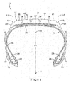
- Fig. 1 is a cross-sectional view of a tire in accordance with the present invention;
- Fig. 2 is an enlarged fragmentary view of the tread of the tire of Fig. 1;
- Fig. 3 is an enlarged fragmentary view similar to Fig. 2 depicting an alternative embodiment of a tire in accordance with the present invention;
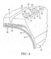
- Fig. 4 is an enlarged fragmentary view similar to Fig. 2 depicting another alternative embodiment of a tire in accordance with the present invention; and
- Fig. 5 is an enlarged fragmentary view similar to Fig. 2 depicting another alternative embodiment of a tire in accordance with the present invention.
- "Axial" and "axially" mean the lines or directions that are parallel to the axis of rotation of the tire.
- "Circumferential" means circular lines or directions extending along the surface of the sidewall perpendicular to the axial direction.
- "Equatorial plane (EP)" means the plane perpendicular to the tire's axis of rotation and passing through the center of its tread.
- "Footprint" means the contact patch or area of contact of the tire tread with a flat surface at zero speed and under design load and pressure.
- "Groove" means an elongated void area in a tread that may extend circumferentially or laterally about the tread in a straight, curved, or zig-zag manner. Grooves ordinarily remain open in the tire footprint.
- "Lateral" means a direction parallel to the axial direction, as in across the width of the tread or crown region.
- "Lateral edge" means the axially outermost edge of the tread as defined by a plane parallel to the equatorial plane and intersecting the outer ends of the axially outermost traction lugs at the radial height of the inner tread surface.
- "Leading" refers to a portion or part of the tread that contacts the ground first, with respect to a series of such parts or portions, during rotation of the tire in the direction of travel.
- "Nonskid" means depth of grooves in a tire tread.
- "Radial" and "radially" mean directions radially toward or away from the axis of rotation of the tire.
- "Rib" means a circumferentially extending strip of rubber on the tread which is defined by at least one circumferential groove.
- "Shoulder" means the upper portion of sidewall just below the tread edge.
- "Sidewall" means that portion of a tire between the tread and the bead area.
- "Sipes" refer to small slots molded into ribs of a tire that subdivide the tread surface and improve traction characteristics. Sipes tend to close completely in a tire footprint and constitute very narrow slots or slits formed by thin metal strips placed in the tire mold, referred to as sipe blades.
- "Tread" means a molded rubber component which, when bonded to a tire casing, includes that portion of the tire that comes into contact with the road when the tire is normally inflated and under normal load.
- "Tread width" means the arc length of the road contacting tread surface in the axial direction, that is, in a plane parallel to the axis of rotation of the tire.
- "Tread Arc Width" (TAW) means the width of an arc having its center located on the equatorial plane (EP) and which substantially coincides with the radially outermost surfaces of the various traction elements (i.e., lugs, blocks, buttons, ribs, etc.) across the lateral or axial width of the tread portions of a tire (i.e., between the lateral edges of the tread) when the tire is mounted upon its designated rim and inflated to its specified inflation pressure but not subject to any load.
- With reference to Fig. 1, a
pneumatic tire 10 of the present invention includes a road-contactingtread 12 extending betweenlateral edges sidewalls 18 extending from thelateral edges shoulder 20 defined at the juncture between eachsidewall 18 andtread 12, and acarcass 22 defining a support structure fortire 10. Thetread 12 andsidewalls 18 are comprised of a suitable material, such as a natural or synthetic rubber compound, selected in accordance with engineering standards accepted in the tire art.Tire 10 may have mirror symmetry for reflection about a mid-circumferential orequatorial plane 25 bisectingtire 10 midway betweenlateral edges tire 10 includes an axis ofrotation 11 that orthogonally intersects theequatorial plane 25. - The
carcass 22 includes a pair ofbeads 24 each having an annularinextensible tensile member 26 and anapex 28. Each of thesidewalls 18 is terminated by a corresponding one of thebeads 24, which provide support for thetire 10 and aid in sealing air in thetire 10. Thecarcass 22 further includes at least onecomposite ply structure 30 having opposite turn-upply ends 32 each wrapped about one of thebeads 24. Tire 10 further includes abelt package 34 typically characterized by a plurality of individual cut belt plies and/or spiral wound belt layers. The construction of thebelt package 34 varies according to the tire construction. The plies of theply structure 30 and thebelt package 34 generally consist of cord reinforced elastomeric material in which the cords may be aramid, steel, fiberglass or polyamide and the elastomer is a vulcanized rubber material. The cord reinforced elastomeric material constituting theply structure 30 andbelt package 34 are encased in and bonded to a suitable material, such as a natural or synthetic rubber compound, selected in accordance with engineering standards accepted in the tire art. - A set of
tires 10 is placed on a vehicle, such as an automobile. When eachtire 10 is mounted on a rim and placed on the vehicle, thetread 12 protects thecarcass 22 andbelt package 34 while providing traction for thetire 10 on the road surface. Tire 10 contains an inflation fluid, like nitrogen, air, or another gas or gas mixture, that sustains the vehicle load. Aliner 35, which may be formed of, for example, halobutyl rubber, defines an air impervious chamber for containing the air pressure when thetire 10 is inflated. - With reference to Figs. 1 and 2, the
tread 12 is partitioned by a plurality of continuous parallelcircumferential grooves 36 into a plurality ofribs tire 10. Any or all of theribs circumferential grooves 36 and that communicate with and intersect thecircumferential grooves 36. Collectively, thecircumferential grooves 36 and the lateral grooves define a relief pattern in any or all of theribs - The
ribs shoulders 20, or shoulder ribs, each includelateral grooves 50 that divide theshoulder rib 44 into a plurality oftransversal ribs 52. Thelateral grooves 50 may have a void-to-rubber ratio of around 50 percent, such a 45 to 55 percent, which is significantly greater than the void-to-rubber ratio of conventional sipes. The void-to-rubber ratio is evaluated across the axial dimension of thelateral grooves 50 and takes into account the rubber contained in thetransversal ribs 52, which extend axially from ashoulder edge 54 to the termination of thelateral grooves 50. The void portion is equal to the volume of thelateral grooves 50 and the rubber portion is equal to the volume of thetransversal ribs 52. - Sipes have a significantly lesser circumferential width and close completely in a tire footprint. In other words, the walls of the sipe contact with each other in the tire footprint, whereas the walls of the
lateral grooves 50 do not contact in the tire footprint. Conventional sipes have a width less than 4 mm, which provides a void-to-rubber ratio for sipes that is significantly less than 50 percent. Thelateral grooves 50 have a depth ranging from 2 mm to 25 percent to 35 percent of the non-skid depth ofcircumferential grooves 36 and have a width between the groove walls greater than 4 mm. - The depth profile of each of the
lateral grooves 50 may not be uniform across therib shoulder edge 54 defined at the intersection betweentread 12 andshoulder 20, especially in the case of a very wide Tread Arc Width (TAW). In certain embodiments of the present invention, the maximum width of the resultingtransversal ribs 52 may be equal to the depth of thelateral grooves 50. After an initial wear stage to a tread height less than the depth oflateral grooves 50, theshoulder rib 46 will have the appearance of a traditional solid shoulder rib. In other words, wear and ablation of theshoulder rib 46 eventually causes thelateral grooves 50 to vanish. - The
lateral grooves 50 include a single transverse groove segment having a groove depth less than the depth ofcircumferential grooves 36. Thelateral grooves 50 extend axially only across a portion of theshoulder rib 46 and do not extend across the full axial dimension of theshoulder rib 46. Consequently, thelateral grooves 50 do not intersect nor communicate with the adjacentcircumferential groove 36. In other words, thelateral grooves 50 terminate within theshoulder rib 46, and have a closed end within therib 46 and an open end defined at theshoulder edge 54. Each of thelateral grooves 50 intersects theshoulder edge 54.Lateral grooves 50 are oriented perpendicular to theequatorial plane 25 andcircumferential groove 36. Similarlateral grooves 50 are provided inshoulder rib 38. However,ribs lateral grooves 50. - The
transversal ribs 52 defined bylateral grooves 50 are prone to buckling, which reduces heat generation and the peak contact pressure of thenew tire 10. Thelateral grooves 50 may contribute to increased mileage due to rubber volume (wider TAW, higher NSK), increased mileage due to less irregular shoulder wear (high contact pressure) at high mileage, and increased durability (lower heat generation and temperature at the shoulder and, therefore, at the breaker edge). - With reference to Fig. 3 in which like reference numerals refer to like features in Fig. 2 and in accordance with an alternative embodiment of the present invention, the
tire 10 may includelateral grooves 58 that are inclined relative to the axial direction and the equatorial plane 25 (Fig. 1). Thelateral grooves 58 are inclined at an angle, α, measured relative to theequatorial plane 25 or, equivalently, the adjacentcircumferential groove 36. Specifically, thelateral grooves 58 may be inclined at any acute angle relative to theequatorial plane 25 or adjacentcircumferential groove 36. Other properties of thelateral grooves 58 are as described above for lateral grooves 50 (Figs. 1 and 2). - With reference to Fig. 4 in which like reference numerals refer to like features in Fig. 2 and in accordance with an alternative embodiment of the present invention, the
tire 10 may includelateral grooves 60 that have a zigzag or V-shaped appearance. Specifically, each of thelateral grooves 60 has a coupled pair ofsegments circumferential groove 36. Each of thesegments lateral grooves 60 are as described above for lateral grooves 50 (Figs. 1 and 2). Thesegments lateral grooves 60 are continuous. - With reference to Fig. 5 in which like reference numerals refer to like features in Fig. 2 and in accordance with an alternative embodiment of the present invention, the
tire 10 may includelateral grooves 62 that are smoothly curved and, therefore, inclined with a continuously varying inclination angle measured relative to the equatorial plane 25 (Fig. 1). Other properties of thelateral grooves 62 are as described above for lateral grooves 50 (Figs. 1 and 2), 58 (Fig. 3), and 60 (Fig. 4). - The invention contemplates that
tire 10 may include a combination of thelateral grooves lateral grooves shoulder ribs
Claims (10)
- A pneumatic tire comprising:a carcass (22) having an axis of rotation (11);a sidewall (18) centered about said axis of rotation and having a shoulder (20); anda tread (12) disposed radially outward of said carcass and joined by said shoulder with said sidewall along an edge (54), said tread (12) including a circumferential groove (36) defining a first shoulder rib (38, 46) adjacent to said shoulder, said shoulder rib extending across an axial width of said tread and including a plurality of lateral grooves (50) intersecting said edge (54), said lateral grooves extending laterally across a portion of said axial width so that said lateral grooves (50) do not intersect said circumferential groove (36).
- The pneumatic tire of claim 1, wherein at least one or each of said lateral grooves (50) is inclined at an angle relative to said circumferential groove (36).
- The pneumatic tire of claim 1 or 2, wherein said lateral grooves (50) have a groove depth that is less than a groove depth of said circumferential groove (36).
- The pneumatic tire of claim 3, wherein said groove depth ranges from 2 millimeters to 35 percent of the groove depth of said circumferential groove.
- The pneumatic tire of at least one of the previous claims, wherein said lateral grooves have a void-to-rubber ratio of 45 to 55 percent, especially about 50 percent.
- The pneumatic tire of at least one of the previous claims, wherein each of said lateral grooves (50) has a circumferential width greater than 4 millimeters.
- The pneumatic tire of at least one of the previous claims, wherein each of said lateral grooves (50) includes a first groove segment (59) inclined at a first angle relative to said circumferential groove and a second groove segment (61) continuous with said first groove segment, said second groove segment being inclined at a second angle relative to said circumferential groove that differs from said first angle.
- The pneumatic tire of at least one of the previous claims, wherein each of said lateral grooves (50) is lengthwise continuously curved in an axial direction.
- The pneumatic tire of at least one of the preceding claims, wherein each of said lateral grooves (50) has a groove depth that is non-uniform across an axial dimension.
- The pneumatic tire of claim 9, wherein said groove depth increases in a direction toward said shoulder edge (54).
Applications Claiming Priority (1)
| Application Number | Priority Date | Filing Date | Title |
|---|---|---|---|
| US11/024,083 US7341082B2 (en) | 2004-12-28 | 2004-12-28 | Shoulder ribs for pneumatic tires |
Publications (1)
| Publication Number | Publication Date |
|---|---|
| EP1676723A1 true EP1676723A1 (en) | 2006-07-05 |
Family
ID=35976403
Family Applications (1)
| Application Number | Title | Priority Date | Filing Date |
|---|---|---|---|
| EP05112460A Withdrawn EP1676723A1 (en) | 2004-12-28 | 2005-12-20 | Pneumatic tire with lateral shoulder grooves |
Country Status (3)
| Country | Link |
|---|---|
| US (1) | US7341082B2 (en) |
| EP (1) | EP1676723A1 (en) |
| BR (1) | BRPI0505599A (en) |
Families Citing this family (9)
| Publication number | Priority date | Publication date | Assignee | Title |
|---|---|---|---|---|
| US20060137795A1 (en) * | 2004-12-27 | 2006-06-29 | Hill Giles A Iii | Tread for solid rubber tire |
| US7926533B2 (en) | 2007-10-31 | 2011-04-19 | The Goodyear Tire & Rubber Company, Inc. | Pneumatic tire with increased lower sidewall durability |
| US8056592B2 (en) * | 2007-10-31 | 2011-11-15 | The Goodyear Tire + Rubber Company, Inc. | Grip tire with added puncture protection |
| US9174498B2 (en) * | 2011-09-22 | 2015-11-03 | The Yokohama Rubber Co., Ltd. | Pneumatic tire |
| US9616716B2 (en) | 2011-12-14 | 2017-04-11 | Bridgestone Americas Tire Operations, Llc | Three dimensional sipe |
| WO2014057548A1 (en) * | 2012-10-10 | 2014-04-17 | 横浜ゴム株式会社 | Pneumatic tire |
| JP5868303B2 (en) * | 2012-10-16 | 2016-02-24 | 横浜ゴム株式会社 | Pneumatic tire |
| USD788026S1 (en) | 2015-09-30 | 2017-05-30 | Bridgestone Americas Tire Operations, Llc | Tire off-shoulder |
| JP2024093506A (en) * | 2022-12-27 | 2024-07-09 | 住友ゴム工業株式会社 | Retreaded tires |
Citations (6)
| Publication number | Priority date | Publication date | Assignee | Title |
|---|---|---|---|---|
| US3841374A (en) * | 1972-04-04 | 1974-10-15 | Michelin & Cie | Tires |
| US3858633A (en) * | 1971-11-08 | 1975-01-07 | Establissements Michelin Raiso | Heavy-duty radial tire for use on and off the road |
| US4271886A (en) * | 1978-10-14 | 1981-06-09 | Continental Gummi-Werke Aktiengesellschaft | Tread for radial tires of trucks and similar vehicles |
| US4281702A (en) * | 1977-08-17 | 1981-08-04 | Uniroyal Engelbert Reifen Gmbh | Pneumatic tire |
| US4567929A (en) * | 1984-05-29 | 1986-02-04 | The Goodyear Tire & Rubber Company | Bias ply pneumatic tire tread with lateral notches |
| JPH09132007A (en) * | 1995-11-10 | 1997-05-20 | Bridgestone Corp | Pneumatic radial tire for passenger car and small truck |
Family Cites Families (14)
| Publication number | Priority date | Publication date | Assignee | Title |
|---|---|---|---|---|
| JPS60179305A (en) * | 1984-02-27 | 1985-09-13 | Toyo Tire & Rubber Co Ltd | Pneumatic tire for car |
| JPS6361606A (en) * | 1986-08-30 | 1988-03-17 | Bridgestone Corp | Pneumatic radial tire |
| JPH01145206A (en) * | 1987-11-30 | 1989-06-07 | Sumitomo Rubber Ind Ltd | Pneumatic tyre |
| US5097882A (en) | 1988-07-11 | 1992-03-24 | The Goodyear Tire & Rubber Company | Tire tread and tire including trapezoidal block elements nested in reentrant angles of zigzag ribs |
| US5327952A (en) | 1991-03-08 | 1994-07-12 | The Goodyear Tire & Rubber Company | Pneumatic tire having improved wet traction |
| US5660652A (en) | 1995-07-14 | 1997-08-26 | The Goodyear Tire & Rubber Company | Truck tire and tread for steer axles |
| US5616195A (en) | 1995-08-28 | 1997-04-01 | The Goodyear Tire & Rubber Company | Low aspect ratio truck tire |
| AU738228B2 (en) | 1996-12-19 | 2001-09-13 | Michelin Recherche Et Technique S.A. | Sacrificial ribs for improved tire wear |
| JP3335118B2 (en) * | 1998-01-19 | 2002-10-15 | 住友ゴム工業株式会社 | Heavy duty tire |
| JP2000108614A (en) * | 1998-10-01 | 2000-04-18 | Bridgestone Corp | Pneumatic tire |
| JP4368978B2 (en) * | 1999-07-29 | 2009-11-18 | 株式会社ブリヂストン | Heavy duty pneumatic radial tire |
| US7464738B2 (en) * | 1999-12-01 | 2008-12-16 | Pirelli Pneumatici S.P.A. | Tyre for a vehicle wheel including zigzag circumferential grooves and blind transverse cuts |
| US6298890B1 (en) * | 1999-12-16 | 2001-10-09 | The Goodyear Tire & Rubber Company | Off-road tire |
| US6564839B1 (en) | 2000-11-01 | 2003-05-20 | The Goodyear Tire & Rubber Company | Pneumatic tire having a load dependent adaptive footprint shape |
-
2004
- 2004-12-28 US US11/024,083 patent/US7341082B2/en not_active Expired - Fee Related
-
2005
- 2005-12-16 BR BRPI0505599-7A patent/BRPI0505599A/en not_active IP Right Cessation
- 2005-12-20 EP EP05112460A patent/EP1676723A1/en not_active Withdrawn
Patent Citations (6)
| Publication number | Priority date | Publication date | Assignee | Title |
|---|---|---|---|---|
| US3858633A (en) * | 1971-11-08 | 1975-01-07 | Establissements Michelin Raiso | Heavy-duty radial tire for use on and off the road |
| US3841374A (en) * | 1972-04-04 | 1974-10-15 | Michelin & Cie | Tires |
| US4281702A (en) * | 1977-08-17 | 1981-08-04 | Uniroyal Engelbert Reifen Gmbh | Pneumatic tire |
| US4271886A (en) * | 1978-10-14 | 1981-06-09 | Continental Gummi-Werke Aktiengesellschaft | Tread for radial tires of trucks and similar vehicles |
| US4567929A (en) * | 1984-05-29 | 1986-02-04 | The Goodyear Tire & Rubber Company | Bias ply pneumatic tire tread with lateral notches |
| JPH09132007A (en) * | 1995-11-10 | 1997-05-20 | Bridgestone Corp | Pneumatic radial tire for passenger car and small truck |
Non-Patent Citations (1)
| Title |
|---|
| PATENT ABSTRACTS OF JAPAN vol. 1997, no. 09 30 September 1997 (1997-09-30) * |
Also Published As
| Publication number | Publication date |
|---|---|
| US7341082B2 (en) | 2008-03-11 |
| BRPI0505599A (en) | 2006-09-19 |
| US20060137790A1 (en) | 2006-06-29 |
Similar Documents
| Publication | Publication Date | Title |
|---|---|---|
| EP1440822B1 (en) | Pneumatic tire | |
| US5238038A (en) | Pneumatic tire | |
| US5660652A (en) | Truck tire and tread for steer axles | |
| EP2818333B1 (en) | Pneumatic tire | |
| US5529103A (en) | Off-the-road pneumatic tire with specified bead area design | |
| US5261474A (en) | Earthmover tire | |
| US8047243B2 (en) | Replacement tread for a truck racing tire | |
| EP1127716B1 (en) | Heel and toe wear balancing | |
| US20080053583A1 (en) | Radial Passenger Tire with Improved Tread Contour | |
| EP0658450B1 (en) | Pneumatic tyre | |
| EP0473860A1 (en) | Tire tread for large motor vehicles | |
| EP1676726B1 (en) | Pneumatic tire having tread blocks with skewed walls | |
| US7341082B2 (en) | Shoulder ribs for pneumatic tires | |
| GB2253817A (en) | Ribbed tire tread having high density siping zones in the rib regions | |
| CN108284711B (en) | Pneumatic tire | |
| US8074690B2 (en) | Decoupling groove for pneumatic tire tread | |
| WO1999036278A1 (en) | Radial passenger tire with improved tread contour with decoupling grooves | |
| JP3254171B2 (en) | Heavy duty pneumatic tires | |
| EP2230104A1 (en) | Tire having tread blocks with blended wall-shapes | |
| EP0748705B1 (en) | Pneumatic tyre | |
| US20040112493A1 (en) | Truck steer tire | |
| JP4388309B2 (en) | Heavy duty tire | |
| EP3988331B1 (en) | Pneumatic tire | |
| JPH08216621A (en) | Retreaded tire | |
| CA2054426A1 (en) | Tread for a pneumatic tire having high density siping zones located in the shoulder regions |
Legal Events
| Date | Code | Title | Description |
|---|---|---|---|
| PUAI | Public reference made under article 153(3) epc to a published international application that has entered the european phase |
Free format text: ORIGINAL CODE: 0009012 |
|
| AK | Designated contracting states |
Kind code of ref document: A1 Designated state(s): AT BE BG CH CY CZ DE DK EE ES FI FR GB GR HU IE IS IT LI LT LU LV MC NL PL PT RO SE SI SK TR |
|
| AX | Request for extension of the european patent |
Extension state: AL BA HR MK YU |
|
| 17P | Request for examination filed |
Effective date: 20070105 |
|
| AKX | Designation fees paid |
Designated state(s): DE FR GB IT |
|
| 17Q | First examination report despatched |
Effective date: 20070212 |
|
| STAA | Information on the status of an ep patent application or granted ep patent |
Free format text: STATUS: THE APPLICATION IS DEEMED TO BE WITHDRAWN |
|
| 18D | Application deemed to be withdrawn |
Effective date: 20090818 |