EP1676543B1 - Artificial sphincter with variable viscosity fluid-filled collar - Google Patents
Artificial sphincter with variable viscosity fluid-filled collar Download PDFInfo
- Publication number
- EP1676543B1 EP1676543B1 EP05257902A EP05257902A EP1676543B1 EP 1676543 B1 EP1676543 B1 EP 1676543B1 EP 05257902 A EP05257902 A EP 05257902A EP 05257902 A EP05257902 A EP 05257902A EP 1676543 B1 EP1676543 B1 EP 1676543B1
- Authority
- EP
- European Patent Office
- Prior art keywords
- collar
- control unit
- electro
- fluid
- artificial sphincter
- Prior art date
- Legal status (The legal status is an assumption and is not a legal conclusion. Google has not performed a legal analysis and makes no representation as to the accuracy of the status listed.)
- Expired - Lifetime
Links
Images




Classifications
-
- A—HUMAN NECESSITIES
- A61—MEDICAL OR VETERINARY SCIENCE; HYGIENE
- A61F—FILTERS IMPLANTABLE INTO BLOOD VESSELS; PROSTHESES; DEVICES PROVIDING PATENCY TO, OR PREVENTING COLLAPSING OF, TUBULAR STRUCTURES OF THE BODY, e.g. STENTS; ORTHOPAEDIC, NURSING OR CONTRACEPTIVE DEVICES; FOMENTATION; TREATMENT OR PROTECTION OF EYES OR EARS; BANDAGES, DRESSINGS OR ABSORBENT PADS; FIRST-AID KITS
- A61F2/00—Filters implantable into blood vessels; Prostheses, i.e. artificial substitutes or replacements for parts of the body; Appliances for connecting them with the body; Devices providing patency to, or preventing collapsing of, tubular structures of the body, e.g. stents
- A61F2/0004—Closure means for urethra or rectum, i.e. anti-incontinence devices or support slings against pelvic prolapse
- A61F2/0031—Closure means for urethra or rectum, i.e. anti-incontinence devices or support slings against pelvic prolapse for constricting the lumen; Support slings for the urethra
- A61F2/0036—Closure means for urethra or rectum, i.e. anti-incontinence devices or support slings against pelvic prolapse for constricting the lumen; Support slings for the urethra implantable
-
- A—HUMAN NECESSITIES
- A61—MEDICAL OR VETERINARY SCIENCE; HYGIENE
- A61B—DIAGNOSIS; SURGERY; IDENTIFICATION
- A61B5/00—Measuring for diagnostic purposes; Identification of persons
- A61B5/07—Endoradiosondes
- A61B5/076—Permanent implantation
-
- A—HUMAN NECESSITIES
- A61—MEDICAL OR VETERINARY SCIENCE; HYGIENE
- A61B—DIAGNOSIS; SURGERY; IDENTIFICATION
- A61B5/00—Measuring for diagnostic purposes; Identification of persons
- A61B5/20—Measuring for diagnostic purposes; Identification of persons for measuring urological functions restricted to the evaluation of the urinary system
- A61B5/202—Assessing bladder functions, e.g. incontinence assessment
-
- A—HUMAN NECESSITIES
- A61—MEDICAL OR VETERINARY SCIENCE; HYGIENE
- A61N—ELECTROTHERAPY; MAGNETOTHERAPY; RADIATION THERAPY; ULTRASOUND THERAPY
- A61N2/00—Magnetotherapy
-
- A—HUMAN NECESSITIES
- A61—MEDICAL OR VETERINARY SCIENCE; HYGIENE
- A61F—FILTERS IMPLANTABLE INTO BLOOD VESSELS; PROSTHESES; DEVICES PROVIDING PATENCY TO, OR PREVENTING COLLAPSING OF, TUBULAR STRUCTURES OF THE BODY, e.g. STENTS; ORTHOPAEDIC, NURSING OR CONTRACEPTIVE DEVICES; FOMENTATION; TREATMENT OR PROTECTION OF EYES OR EARS; BANDAGES, DRESSINGS OR ABSORBENT PADS; FIRST-AID KITS
- A61F2250/00—Special features of prostheses classified in groups A61F2/00 - A61F2/26 or A61F2/82 or A61F9/00 or A61F11/00 or subgroups thereof
- A61F2250/0001—Means for transferring electromagnetic energy to implants
- A61F2250/0002—Means for transferring electromagnetic energy to implants for data transfer
Definitions
- the invention relates to a system for supplementing the function of the sphincter muscle by changing the viscosity state of fluid within a collar that encircles a portion of an anatomical conduit controlled by the sphincter muscle.
- Control of urinary continence depends on the function of the sphincter muscle straddling the urethra of a person. Ideally, the sphincter muscle squeezes the urethra to stop the flow of urine from the bladder and relaxes to open the passageway of the urethra when elimination of urine from the bladder through the urethra is desired. Over time, the function of the anatomical sphincter muscles can become damaged, weakened, or otherwise impaired such that the sphincter muscle is partially or completely unable to squeeze the urethra sufficiently to prevent unintended flowing of fluids from the bladder. As a result, incontinence may occur. Artificial sphincters have been developed to treat incontinence in persons having weakened or otherwise impaired sphincter muscles.
- Figure 1 shows an exemplary conventional artificial sphincter control system.
- the system shown in Figure 1 comprises a cuff 10, a pump 20, a balloon reservoir 30 and tubing 40 connecting the various components to one another.
- Such artificial sphincters are typically surgically implanted in a patient through incisions in the lower abdomen and labia for females, and in the abdomen, scrotum, and between the scrotum and anus for males.
- Figure 2 illustrates such a conventional device implanted in a male.
- the cuff 10 surrounds a portion of the urethra U, the pump 10 is placed within the scrotum S, and the balloon reservoir 30 is placed in the lower abdomen A. Tubes 40 connect the various components.
- the conventional cuff 10 is inflated using fluid from the balloon reservoir 30.
- the inflated cuff 10 squeezes that portion of the urethra U that is surrounded with the cuff.
- the inflated cuff 10 squeezes the urethra closed and thus stops urine from flowing from the bladder B through the urethra.
- the pump 20 placed within the scrotum S as shown in Figure 2 , controls the movement of fluid to and from the cuff 10 and the balloon reservoir 30.
- manually pressing the pump 20 deflates the cuff 10 by displacing fluid from the cuff 10 to the balloon reservoir 30.
- the urethra is opened and urine is able to pass there-through for elimination from the body.
- fluid automatically leaves the balloon reservoir 30 and returns to the cuff 10 to inflate the cuff 10 once again.
- the urethra is generally squeezed closed and urine does not pass therethrough.
- US 5509888 discloses a device and method for regulating fluid flow within an anatomical conduit wherein a collar containing a magneto-rheological fluid is activated and deactivated to allow or restrict the flow of fluid.
- US2003/0144575 is a further example of an apparatus for treating a urinary incontinence. This device uses a mechanical drive to change the size of the opening within the collar.
- the system of the invention provides an artificial sphincter system for supplementing the function of an anatomical sphincter muscle of a patient.
- the artificial sphincter system comprises at least a collar surrounding a portion of an anatomical conduit, such as an urethra, and a variable viscosity fluid contained within the collar.
- an anatomical conduit such as an urethra
- a variable viscosity fluid contained within the collar.
- the variable viscosity fluid When liquefied, the variable viscosity fluid renders the collar pliable permitting the anatomical conduit surrounded by the collar to expand freely and pass bodily fluids therethrough the anatomical conduit, as from a bladder.
- the variable viscosity fluid renders the collar rigid thereby restricting the anatomical conduit from expanding and restricting bodily fluids from passing therethrough the anatomical conduit.
- Changes in the state of the electro-rheological fluid thus determine whether the collar restricts or permits bodily fluids to pass through that portion of the anatomical conduit surrounded by the collar.
- the lower the viscosity level of the fluid in the collar the more pliable the collar is.
- the system of the invention further provides an artificial sphincter system wherein the electro-rheologic fluid is comprised of a suspension of dielectric particles that change state when exposed to an electric field.
- the electro-rheologic fluid tends to solidify when exposed to conditions such as an electrical potential difference, thus rendering the collar more rigid, which in turn restricts the anatomical conduit from expanding and thus restricts the flow of bodily fluids through that portion of the anatomical conduit surrounded by the collar.
- the electro-rheologic fluid tends to be more liquified, thus rendering the collar more pliable, which in turn permits expansion of the anatomical conduit and thus permits bodily fluids to flow more easily through the anatomical conduit surrounded by the collar.
- system of the invention further provides an implanted control unit, or battery, connected to the collar.
- An electrical potential difference generated by the implanted control unit, or battery, and communicated to the collar causes the electro-rheologic fluid to solidify.
- the electro-rheologic fluid tends to liquefy.
- the implanted control unit, or battery generates the electrical potential difference in response to sensed pressure data from a sensor placed within the anatomical conduit or organ to be emptied through the anatomical conduit, or in response to operator input provided to an external control unit operable at will by the patient and that communicates with the implantable control unit, or battery.
- inventions of the system of the invention omit the implantable control device, or battery, and instead extend the wire connected to the collar to a position located external to the patient's body.
- the wires connected to the collar communicate the electrical potential difference to the collar in similar manner based on pressure data sensed from a sensor placed within the anatomical conduit or organ to be emptied through the anatomical conduit, or in response to operator input provided to the external control unit.
- a pressure sensor is provided in the anatomical conduit or organ to be emptied through the anatomical conduit upstream of the collar.
- the sensor can be a wireless sensor that communicates with the implanted control unit or battery, or the sensor can be a wired sensor physically connected to the implanted control unit or battery. Regulation of the collar and the state of the electro-rheological fluid contained therein by the generation of the electric, is thus determined by data sensed by the pressure sensor or by operation of the external control unit by the patient.
- the various methods of supplementing control of an anatomical conduit surrounded in part by the collar containing electro-rheological fluid according to the invention comprise at least permitting bodily fluids to flow through the anatomical conduit by liquefying the electro-rheological fluid in the collar to permit expansion of the anatomical conduit, and restricting the flow of bodily fluids through the anatomical conduit by solidifying the electro-rheological fluid in the collar and restricting the anatomical conduit from expanding, which in turn restricts the flow of bodily fluids there-through.
- the collar may comprise a single chamber within which the electro-rheological fluid is contained, or may comprise a plurality of compartments within which the electro-rheological fluid is contained.
- the system of the invention can be used in a method for supplementing a natural sphincter muscle, the method comprising:
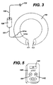
- Fig. 3 illustrates various components of one embodiment of an artificial sphincter system according to the invention.
- the artificial sphincter system is comprised of a collar 110 containing a variable viscosity fluid, an implantable control unit 120 connected to the collar, and a sensor 130 connected to the implantable control unit 120.
- the collar 110 surrounds an anatomical conduit, such as an urethra U ( Fig. 4 ).
- the state of the variable viscosity fluid within the collar 110 determines the rigidity or pliability of the collar 110 and thus the expandibility of the anatomical conduit.
- Fig. 5 illustrates an external control unit 140 usable in combination with the various artificial sphincter systems and methods described herein.
- the collar 110 is comprised generally of flexible, bio-compatible material as known in the art.
- the collar 110 is biased in a circular, or semi-circular, configuration such that when placed about an anatomical conduit, such as an urethra U, the collar 110 will encircle an outer wall of the anatomical conduit.
- a variable viscosity fluid such as, for example, an electro-rheologic fluid, is contained within the collar 110.
- Closed ends 111, 112 of the collar 110 help to retain the variable viscosity fluid within the collar 110.
- the closed ends 111, 112 may be separated slightly from each other prior to placement of the collar 110 about the anatomical conduit in order to place the collar 110 around the desired anatomical conduit.
- a securing device such as a clamp, buttons, snaps, sutures, or other device known in the art.
- Fig. 8 illustrates another collar 1110 having compartments 1111 for containing the variable viscosity fluid therein, as described in more detail below with respect to Fig. 7 .
- the implantable control unit 120 which may comprise a battery, may be connected to the collar 110 by a wire 121, having two leads 121a, 121b connected to the collar 110. An electrical potential difference can thus be applied and communicated to the collar 110 through the two leads 121a, 121b.
- the length of wire 121 can vary to accommodate placement of the implantable control unit 120, or battery, at different locations within the body of the patient. Typically, the implantable control unit 120, or battery, is placed within the lower abdominal regions of the patient, although the artisan will readily appreciate that placement of the implantable control unit 120, or battery, at other locations within the patient's body is within the scope of the invention by varying the length of the wire 121.
- the implantable control unit 120 may also be connected to the sensor 130 by a wire 122.
- the sensor 130 is typically located upstream of the collar 110 within the anatomical conduit, or within an organ that is to be emptied through the anatomical conduit.
- the length of wire 122 may be varied to accommodate the placement of the implantable control unit 120, or battery, and the placement of the sensor 130 as desired.
- the wire 122 may be omitted and the sensor 130 and implantable control unit 120, or battery, may wirelessly communicate with one another.
- the collar 110 is placed to encircle the anatomical conduit U.
- the implantable control unit 120, or battery is placed within the patient's body (portions shown schematically in dashed lines).
- an electric current provided from the implantable control unit 120, or battery, and through the wire 121 and leads 121a, 121b to the collar 110 that generates an electrical potential difference.
- the electrical potential difference changes the electro-rheological fluid in the collar 110.
- the presence of the electrical potential difference solidifies the electro-rheologic fluid in the collar 110, whereas the absence of the electric potential difference liquefies the fluid in the collar.
- the sensor 130 is located anatomically upstream of the collar 110 within the anatomical conduit or organ to be emptied through the anatomical conduit that the collar 110 is placed upon.
- the sensor 130 collects bodily fluid pressure data within the anatomical conduit or organ to be emptied through the anatomical conduit.
- the wire 122 shown in Fig. 4 is omitted, as should be readily appreciated by the artisan.
- the implantable control unit 120 may be provided with "ON” and "OFF" modes.
- the implantable control unit 120 When in the "ON” mode, for example, the implantable control unit 120 generates an electrical potential difference, for example.
- the implantable control unit 120 When in the "OFF” mode, the implantable control unit 120 does not generate an electrical potential difference.
- the electrical potential difference generated by the implantable control unit 120 solidifies the variable viscosity fluid within the collar 110.
- the solidified variable viscosity fluid in the collar 110 restricts the anatomical conduit from expanding, which restricts fluid from passing through the anatomical conduit.
- the implantable control unit 120 When the implantable control unit 120 is in the "OFF” mode the electrical potential difference is terminated or absent.
- the variable viscosity fluid in the collar 110 liquefies, rendering the collar 110 pliable, which permits the anatomical conduit to expand.
- the expanded anatomical conduit permits fluid to flow through the anatomical conduit when intended.
- Switching the implantable control unit 120 between the "ON” and “OFF” modes can occur automatically based on sensed pressure data received by the sensor 130. For example, when sensed pressure meets or exceeds a pre-programmed pressure threshold level, the mode of the implantable control unit may be switched from “ON” to "OFF". Alternatively, when the patient manually operates an external control unit 140 ( Fig. 5 ) provided with overriding Active input state having “Collar ON” and “Collar OFF" modes, then the implantable control unit mode may be switched accordingly to comply with the selected “Collar ON” or “Collar OFF" mode of the external control unit 140.
- the implantable control unit 120 is pre-programmed with the pre-set pressure threshold level.
- pre-set pressure level varies according to organ or anatomical conduit capacities and according to patient preferences, as the artisan should appreciate. Generally, the lower the pre-set pressure threshold level of the sensor 130, the more often the implantable control unit 120 will generate an electrical potential difference.
- the implantable control unit 120 can also be automatically switched from an "ON" mode to an "OFF” mode based on a pre-programmed upper pressure limit.
- the pre-programming aspects of the invention will be described in further detail below.
- the battery where provided as the implantable control unit 120, may provide the electrical potential difference to the leads 121 a, 121b whenever the battery is energized.
- the battery may be normally de-energized, or "OFF", such that the electrical potential difference is normally absent.
- the battery may be automatically de-energized according to sensed pressure data received from the sensor 130, or according to patient operation of the external control unit 140 ( Fig. 6 ). When energized, the battery would generate an electrical potential difference that solidifies the variable viscosity fluid within the collar.
- the sensor 130 communicates the excess level to the battery, causing the battery to de-energize and terminate production of the electrical potential difference.
- the variable viscosity fluid in the collar 110 is liquefied as a result.
- the collar 110 becomes pliable permitting expansion of the anatomical conduit surrounded by the collar 110, and fluid flow therethrough the anatomical conduit.
- Fig. 5 illustrates an external control unit 140 that is operated at will by the patient.
- the external control unit 140 is provided with an Active input state and an Inactive state. In the Inactive state, the external control unit 140 does not influence the operation of the implanted control unit 120.
- the external control unit 140 responds to the "Collar ON” or “Collar OFF” mode selected an input to the external control unit by the patient.
- the "Collar ON” or “Collar OFF” mode is thus communicated wirelessly to the implantable control unit 120, or battery, by the patient.
- the external control unit 140 includes a "Collar ON” button 141, a "Collar OFF” button 142, and a display screen 143.
- the external control unit 140 When the external control unit 140 is in the Active state and in the "Collar ON” mode, the external control unit 140 overrides the sensor 130 and the implantable control unit 120 "OFF" mode and causes the implantable control unit 120, or battery, to generate an electrical potential difference between the leads 121a, 121b that is communicated to the collar 110 to solidify the electro-rheologic fluid in the collar regardless of the sensed pressure data received by the sensor 130.
- the external control unit 140 When the external control unit 140 is in the Active state and in the "Collar OFF” mode, the external control unit 140 overrides the sensor 130 and the implantable control unit "ON" mode and terminates the electrical potential difference from the implantable control unit, thereby liquefying the electro-rheological fluid within the collar. The patient can easily identify what state and mode the external control unit 140 is in by glancing at the display screen 143.
- Figures 6A-6C illustrate exemplary stages of deployment of an anatomically placed artificial sphincter system according to the invention. More specifically, Figures 6A-6C show various states of deployment of the variable viscosity fluid-filled collar 110 around an anatomical conduit, wherein the state of deployment of the collar 110 corresponds to the state of the variable viscosity fluid within the collar 110 and the implanted control unit 120 has been pre-programmed to switch from an "OFF" mode to an "ON” mode when a pre-set pressure threshold limit is met or exceeded, and to switch from the "ON" mode to an "OFF” mode when a pre-set upper pressure limit in one of the bladder B, or anatomical conduit U, has been reached.
- Fig. 6A shows the collar 110 in a soft, pliable state overlying the natural sphincter muscle (not shown) and surrounding the anatomical conduit U.
- the organ, for example bladder B, to be emptied through the anatomical conduit U shown in Fig. 6A is experiencing a pressure level below the pre-programmed threshold level.
- the natural sphincter muscle is thus adequate to restrict fluid flow through the anatomical conduit U in this case.
- the implanted control unit 120 is in a normally "OFF" mode, the patient need not override the implanted control unit 120 by operating the external control unit 140 to an "OFF" mode.
- the external control unit 140 may be in the Inactive state therefore.
- the variable viscosity fluid within the collar 110 is thus liquefied in Fig. 6A
- the implanted control unit 120 switches from the normally "OFF” mode of Fig. 6A , to the "ON" mode.
- an electrical potential difference is generated by the implanted control unit 120 and applied to the collar 110 via the leads 121 a, 121 b.
- the electrical potential difference causes the variable viscosity fluid within the collar 100 to solidify and restrict fluid flow through the urethra U, as shown in Fig. 6B .
- an upper pressure limit is also pre-programmed into the implantable control unit 120 according to the patient's individual bladder B or urethra U capacities, for example.
- the upper pressure limit is programmed into the implanted control unit 120 in conventional manner using the programming means, such as the computer and software, discussed above with respect to the pre-set pressure threshold limits.
- the implanted control unit 120 switches from the "ON" mode to the "OFF" mode when the upper pressure limit in the bladder B or urethra U is approached.
- the upper pressure limit within the bladder B or conduit U may be approached as a result of the natural accumulation of bodily fluids therein, and/or by the patient's exercising of abdominal and/or pelvic muscles.
- the implanted control unit 120 is pre-programmed to switch from the "ON" mode to the "OFF" mode only after the pre-programmed upper pressure limit has been sustained for a pre-determined time limit, for example 3 seconds.
- a pre-determined time limit for example 3 seconds.
- the predetermined time limit should be long enough to avoid accidental switching of the implanted control unit to "OFF" by a brief application of abdominal muscles, which could be caused by sudden and brief peaks in bladder pressure, e.g., during sneezing.
- the electric potential difference should remain absent for a period of time, for example, one minute in order to permit the organ or anatomical conduit to empty sufficiently.
- the organ or conduit would empty sufficiently to effect a pressure drop in the organ or anatomical conduit below the upper threshold.
- the implanted control unit 120, or battery will not switch to its "ON" mode too soon, i.e., in the middle of the act of emptying the organ or anatomical conduit, such as one's bladder.
- the patient may also choose at any time to operate the external control unit 140 to the Active state and the "Collar OFF" mode thereby overriding the "ON" mode of the implantable control unit 120.
- the implantable control unit 120 With the external control unit in the Active state and the "Collar OFF" mode, the implantable control unit 120 does not generate an electrical potential difference, and the variable viscosity fluid in the collar 110 is liquefied.
- the override of the implanted control unit 120 by operation of the external control unit 140 would expire after a designated time period.
- the implanted control unit 120 would resume its normally “OFF” state until either the pre-set pressure threshold limit is exceeded or the external control unit 140 is switched to the Active state and the "Collar ON” mode to override the normally "OFF” state of the implanted control unit.
- the impanted control unit 120 is switched to the "ON" mode.
- the implanted control unit 120 thus generates an electrical potential difference that is communicated to the collar via the leads 121a, 121b.
- the variable viscosity fluid in the collar 110 is solidified, which restricts the anatomical conduit U from expanding, which in turn restricts the unintentional flow of fluids from the organ B through the anatomical conduit U.
- the implanted control unit 120 is switched to the "OFF" mode. Switching the implanted control unit 120 to the "OFF" mode terminates the electrical potential difference, which liquefies the variable viscosity fluid and renders the collar 110 pliable. Expansion of the anatomical conduit U and elimination of the fluid from the organ B through the anatomical conduit U as shown by arrow a is thus permitted. Of course, the implanted control unit 120 automatically switches to the "OFF" mode whenever the pre-programmed upper pressure limit is approached.
- the pre-set pressure threshold limit for each patient is set slightly below that limit at which the natural sphincter becomes insufficient. Such pre-set pressure threshold limits are therefore pre-programmed into the implantable control unit 120 according to individual patient needs.
- the pre-set pressure threshold limits are input to the implanted control unit 120 using programming means such as, for example, software and a computer that communicates the various settings to the implanted control unit 120 in conventional manner.
- the pre-set pressure threshold levels can be re-programmed into the implantable control unit 120 to accommodate changing needs or conditions of the patient.
- the upper pressure limit is similarly pre-programmed into the implanted control unit 120.
- the pre-determined time limit that the upper pressure limit must be sustained for before switching the implantable control unit 120 from the "ON" mode to the "OFF” mode is also pre-programmed into the implanted control unit.
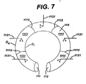
- Fig. 7 illustrates another embodiment of a collar 1110 according to the invention, wherein like numerals refer to like features.
- the collar 1110 shown in Fig. 7 is generally the same as the collar 110 described above with respect to Figs. 1-6 , for example, but in addition comprises a plurality of compartments 1111 throughout the collar 1110.
- the compartments 1111 are created by internal walls 1112 connecting the outer diameter D o and the inner diameter D i of the collar 1110.
- Each of the compartments 1111 contains variable viscosity fluid as described above.
- variable viscosity fluid in each of the compartments 1111 can be independently controlled such that all of the compartments liquefy or solidify at the same time, or such that alternating ones of the compartments solidify and the remaining compartments are liquefied.
- Wires 1121 and leads 1121a, 1121 b connect the compartments 1111 to the implanted control unit 120 to independent change the state of compartments 1111 of the collar where electro-rheologic fluid is contained within the collar 1110.
- Fig. 8 illustrates yet another embodiment of the system of the invention with respect to a collar filled with an electro-rheologic fluid, wherein like numerals refer to like features where appropriate.
- the embodiment of Fig. 8 is generally the same as the embodiment of Fig. 4 except that the implantable control unit 120 is omitted in Fig. 8 . Because the implanted control unit 120 is omitted, the wire 121_extends from the collar 110, where leads 121a, 121b connect the wire 121 to the collar 110, to a location external of the patient's body, as shown in Fig. 8 .
- the wire 121 connects to another control unit 320 external of the body.
- the sensor 130 is placed in the organ or anatomical conduit and communicates sensed data to the control unit 320 to generate an electrical potential difference across the leads 121a, 121 b on the collar.
- the sensor 130 may be a wireless sensor as described above with respect to Fig. 4 , or may be hard-wired using wire 122 in conventional manner as discussed above.
- the presence or absence of an electric potential difference determines the state of the electro-rheologic fluid within the collar as before, wherein the presence of an electrical potential difference solidifies the fluid in the collar, and the absence of the electrical potential difference liquefies the fluid in the collar.
- control unit 320 may be adhered to the skin of the patient, may be fitted to the patient in a belt, or may be otherwise fitted externally to the patient in an other equally conventional manner.
- the external nature of the control unit 320 may render the unit easier to service than implantable counterparts.
Landscapes
- Health & Medical Sciences (AREA)
- Life Sciences & Earth Sciences (AREA)
- General Health & Medical Sciences (AREA)
- Public Health (AREA)
- Engineering & Computer Science (AREA)
- Biomedical Technology (AREA)
- Animal Behavior & Ethology (AREA)
- Veterinary Medicine (AREA)
- Urology & Nephrology (AREA)
- Heart & Thoracic Surgery (AREA)
- Surgery (AREA)
- Medical Informatics (AREA)
- Biophysics (AREA)
- Physics & Mathematics (AREA)
- Molecular Biology (AREA)
- Pathology (AREA)
- Oral & Maxillofacial Surgery (AREA)
- Cardiology (AREA)
- Transplantation (AREA)
- Vascular Medicine (AREA)
- Nuclear Medicine, Radiotherapy & Molecular Imaging (AREA)
- Radiology & Medical Imaging (AREA)
- Physiology (AREA)
- Prostheses (AREA)
- Measuring And Recording Apparatus For Diagnosis (AREA)
Abstract
Description
- The invention relates to a system for supplementing the function of the sphincter muscle by changing the viscosity state of fluid within a collar that encircles a portion of an anatomical conduit controlled by the sphincter muscle.
- Control of urinary continence depends on the function of the sphincter muscle straddling the urethra of a person. Ideally, the sphincter muscle squeezes the urethra to stop the flow of urine from the bladder and relaxes to open the passageway of the urethra when elimination of urine from the bladder through the urethra is desired. Over time, the function of the anatomical sphincter muscles can become damaged, weakened, or otherwise impaired such that the sphincter muscle is partially or completely unable to squeeze the urethra sufficiently to prevent unintended flowing of fluids from the bladder. As a result, incontinence may occur. Artificial sphincters have been developed to treat incontinence in persons having weakened or otherwise impaired sphincter muscles.
-
Figure 1 shows an exemplary conventional artificial sphincter control system. The system shown inFigure 1 comprises acuff 10, apump 20, aballoon reservoir 30 andtubing 40 connecting the various components to one another. Such artificial sphincters are typically surgically implanted in a patient through incisions in the lower abdomen and labia for females, and in the abdomen, scrotum, and between the scrotum and anus for males.Figure 2 illustrates such a conventional device implanted in a male. - As shown in
Figure 2 , thecuff 10 surrounds a portion of the urethra U, thepump 10 is placed within the scrotum S, and theballoon reservoir 30 is placed in the lowerabdomen A. Tubes 40 connect the various components. In practice, theconventional cuff 10 is inflated using fluid from theballoon reservoir 30. The inflatedcuff 10 squeezes that portion of the urethra U that is surrounded with the cuff. The inflatedcuff 10 squeezes the urethra closed and thus stops urine from flowing from the bladder B through the urethra. - The
pump 20, placed within the scrotum S as shown inFigure 2 , controls the movement of fluid to and from thecuff 10 and theballoon reservoir 30. For example, manually pressing thepump 20 deflates thecuff 10 by displacing fluid from thecuff 10 to theballoon reservoir 30. When thecuff 10 is deflated, the urethra is opened and urine is able to pass there-through for elimination from the body. After a designated time period has passed, for example, 2-3 minutes, fluid automatically leaves theballoon reservoir 30 and returns to thecuff 10 to inflate thecuff 10 once again. As before, when thecuff 10 is fully inflated, the urethra is generally squeezed closed and urine does not pass therethrough. - Although the systems and methods of known artificial sphincters, such as those described above, offer supplemental function to a compromised sphincter muscle, the placement of the pump in the labia or scrotum of an individual can interfere with other physical activities. Moreover, inadequate emptying of the bladder may occur if the
cuff 10 becomes re-inflated too quickly, as might occur when thepump 10 is insufficiently depressed such that only small amounts of fluid are displaced from thecuff 10 to theballoon reservoir 30. Still further, the network of artificial conduits connecting the pump, the collar and the balloon reservoir of conventional systems is subject to infection and/or stoppages that can render the device unreliable. Such problems are often only remedied by additional surgeries. -
US 5509888 discloses a device and method for regulating fluid flow within an anatomical conduit wherein a collar containing a magneto-rheological fluid is activated and deactivated to allow or restrict the flow of fluid.US2003/0144575 is a further example of an apparatus for treating a urinary incontinence. This device uses a mechanical drive to change the size of the opening within the collar. - In view of the above, a need exists for systems that simplify and render more reliable the supplemental control of an anatomical sphincter muscle.
- The system of the invention provides an artificial sphincter system for supplementing the function of an anatomical sphincter muscle of a patient. The artificial sphincter system comprises at least a collar surrounding a portion of an anatomical conduit, such as an urethra, and a variable viscosity fluid contained within the collar. When liquefied, the variable viscosity fluid renders the collar pliable permitting the anatomical conduit surrounded by the collar to expand freely and pass bodily fluids therethrough the anatomical conduit, as from a bladder. When solidified, the variable viscosity fluid renders the collar rigid thereby restricting the anatomical conduit from expanding and restricting bodily fluids from passing therethrough the anatomical conduit.
- Changes in the state of the electro-rheological fluid thus determine whether the collar restricts or permits bodily fluids to pass through that portion of the anatomical conduit surrounded by the collar. Generally, the lower the viscosity level of the fluid in the collar the more pliable the collar is. The more pliable the collar is, the more easily bodily fluids are passed there-through that portion of the anatomical conduit surrounded by the collar.
- The system of the invention further provides an artificial sphincter system wherein the electro-rheologic fluid is comprised of a suspension of dielectric particles that change state when exposed to an electric field. The electro-rheologic fluid tends to solidify when exposed to conditions such as an electrical potential difference, thus rendering the collar more rigid, which in turn restricts the anatomical conduit from expanding and thus restricts the flow of bodily fluids through that portion of the anatomical conduit surrounded by the collar. Conversely, in the absence of an electrical potential difference, the electro-rheologic fluid tends to be more liquified, thus rendering the collar more pliable, which in turn permits expansion of the anatomical conduit and thus permits bodily fluids to flow more easily through the anatomical conduit surrounded by the collar.
- In some embodiments of the system of the invention further provides an implanted control unit, or battery, connected to the collar. An electrical potential difference generated by the implanted control unit, or battery, and communicated to the collar causes the electro-rheologic fluid to solidify. When the electrical potential difference is not generated and communicated to the collar, the electro-rheologic fluid tends to liquefy. The implanted control unit, or battery, generates the electrical potential difference in response to sensed pressure data from a sensor placed within the anatomical conduit or organ to be emptied through the anatomical conduit, or in response to operator input provided to an external control unit operable at will by the patient and that communicates with the implantable control unit, or battery.
- Other embodiments of the system of the invention omit the implantable control device, or battery, and instead extend the wire connected to the collar to a position located external to the patient's body. The wires connected to the collar communicate the electrical potential difference to the collar in similar manner based on pressure data sensed from a sensor placed within the anatomical conduit or organ to be emptied through the anatomical conduit, or in response to operator input provided to the external control unit.
- In the various embodiments of the system according to the invention, a pressure sensor is provided in the anatomical conduit or organ to be emptied through the anatomical conduit upstream of the collar. The sensor can be a wireless sensor that communicates with the implanted control unit or battery, or the sensor can be a wired sensor physically connected to the implanted control unit or battery. Regulation of the collar and the state of the electro-rheological fluid contained therein by the generation of the electric, is thus determined by data sensed by the pressure sensor or by operation of the external control unit by the patient.
- The various methods of supplementing control of an anatomical conduit surrounded in part by the collar containing electro-rheological fluid according to the invention comprise at least permitting bodily fluids to flow through the anatomical conduit by liquefying the electro-rheological fluid in the collar to permit expansion of the anatomical conduit, and restricting the flow of bodily fluids through the anatomical conduit by solidifying the electro-rheological fluid in the collar and restricting the anatomical conduit from expanding, which in turn restricts the flow of bodily fluids there-through. The collar may comprise a single chamber within which the electro-rheological fluid is contained, or may comprise a plurality of compartments within which the electro-rheological fluid is contained.
- The above and other features of the invention, including various novel details of construction and combinations of parts, will now be more particularly described with reference to the accompanying drawings and claims. It will be understood that the various exemplary embodiments of the invention described herein are shown by way of illustration only and not as a limitation thereof.
- The system of the invention can be used in a method for supplementing a natural sphincter muscle, the method comprising:
- providing a collar surrounding a portion of an anatomical conduit;
- providing a electro-rheological fluid within the collar, the electro-rheological fluid changeable between at least a liquefied state and a solidified state;
- providing a sensor that receives pressure data from the anatomical conduit or organ to be emptied through the anatomical conduit; providing a first control unit having an "ON" mode that creates conditions to change the variable viscosity fluid within the collar from the liquefied state to the solidified state, and an "OFF" mode that terminates the conditions and returns the electro-rheological fluid from the solidified state to the liquefied state;
- providing an external control unit operable by a patient, the external control unit having an active input state that overrides the first control unit mode, and an inactive state that defers to the first control unit mode;
- determining the first control unit mode according to the pressure data received by the sensor or according to the external control unit; and
- supplementally controlling the flow of fluid through the anatomical conduit by controlling the electro-rheological fluid in the collar according to the presence or absence of the created conditions, whereby the liquefied fluid in the collar permits fluid flow through the anatomical conduit and the solidified fluid in the collar restricts fluid flow through the anatomical conduit.
- Embodiments of the present invention will now be described by way of example with reference to the accompanying drawings, in which:
-
Figure 1 illustrates components of a conventional artificial sphincter system; -
Figures 2 illustrates the placement of the conventional artificial sphincter system ofFigure 1 about a male anatomy; -
Figure 3 illustrates one embodiment of an artificial sphincter system having an electro-rheologic fluid contained within the collar according to the invention; -
Figure 4 illustrates the anatomical placement of the system ofFigure 3 ; -
Figure 5 illustrates an external control unit according to the invention; -
Figure 6A-6C schematically illustrates various states of the variable viscosity fluid during deployment of the collar according to the invention; -
Figure 7 illustrates an embodiment of a compartmentalized collar according to the invention; and -
Figure 8 illustrates another embodiment of a collar containing electro-rheological fluid without an implantable control unit according to the invention. -
Fig. 3 illustrates various components of one embodiment of an artificial sphincter system according to the invention. As shown inFig. 3 , the artificial sphincter system is comprised of acollar 110 containing a variable viscosity fluid, animplantable control unit 120 connected to the collar, and asensor 130 connected to theimplantable control unit 120. Thecollar 110 surrounds an anatomical conduit, such as an urethra U (Fig. 4 ). The state of the variable viscosity fluid within thecollar 110 determines the rigidity or pliability of thecollar 110 and thus the expandibility of the anatomical conduit.Fig. 5 illustrates anexternal control unit 140 usable in combination with the various artificial sphincter systems and methods described herein. - Referring again to
Fig. 3 , thecollar 110 is comprised generally of flexible, bio-compatible material as known in the art. Preferably, thecollar 110 is biased in a circular, or semi-circular, configuration such that when placed about an anatomical conduit, such as an urethra U, thecollar 110 will encircle an outer wall of the anatomical conduit. A variable viscosity fluid, such as, for example, an electro-rheologic fluid, is contained within thecollar 110. Closed ends 111, 112 of thecollar 110 help to retain the variable viscosity fluid within thecollar 110. The closed ends 111, 112 may be separated slightly from each other prior to placement of thecollar 110 about the anatomical conduit in order to place thecollar 110 around the desired anatomical conduit. Once in place around the anatomical conduit, the closed ends 111, 112 of thecollar 110 are aligned with and secured to one another using a securing device (not shown), such as a clamp, buttons, snaps, sutures, or other device known in the art.Fig. 8 illustrates another collar 1110 havingcompartments 1111 for containing the variable viscosity fluid therein, as described in more detail below with respect toFig. 7 . - Referring again to
Fig. 3 , theimplantable control unit 120, which may comprise a battery, may be connected to thecollar 110 by awire 121, having twoleads collar 110. An electrical potential difference can thus be applied and communicated to thecollar 110 through the twoleads wire 121 can vary to accommodate placement of theimplantable control unit 120, or battery, at different locations within the body of the patient. Typically, theimplantable control unit 120, or battery, is placed within the lower abdominal regions of the patient, although the artisan will readily appreciate that placement of theimplantable control unit 120, or battery, at other locations within the patient's body is within the scope of the invention by varying the length of thewire 121. - The
implantable control unit 120, or battery, may also be connected to thesensor 130 by awire 122. Thesensor 130 is typically located upstream of thecollar 110 within the anatomical conduit, or within an organ that is to be emptied through the anatomical conduit. The length ofwire 122 may be varied to accommodate the placement of theimplantable control unit 120, or battery, and the placement of thesensor 130 as desired. Alternatively, thewire 122 may be omitted and thesensor 130 andimplantable control unit 120, or battery, may wirelessly communicate with one another. - In practice, as shown more clearly in
Fig. 4 , thecollar 110 is placed to encircle the anatomical conduit U. Theimplantable control unit 120, or battery, is placed within the patient's body (portions shown schematically in dashed lines). In the case of acollar 110 filled with an electro-rheologic fluid, an electric current provided from theimplantable control unit 120, or battery, and through thewire 121 and leads 121a, 121b to thecollar 110 that generates an electrical potential difference. The electrical potential difference changes the electro-rheological fluid in thecollar 110. For example, the presence of the electrical potential difference solidifies the electro-rheologic fluid in thecollar 110, whereas the absence of the electric potential difference liquefies the fluid in the collar. - The
sensor 130 is located anatomically upstream of thecollar 110 within the anatomical conduit or organ to be emptied through the anatomical conduit that thecollar 110 is placed upon. Thesensor 130 collects bodily fluid pressure data within the anatomical conduit or organ to be emptied through the anatomical conduit. Where thesensor 130 andimplantable control unit 120, or battery, are wireless, thewire 122 shown inFig. 4 is omitted, as should be readily appreciated by the artisan. - Referring still to
Fig. 4 , theimplantable control unit 120 may be provided with "ON" and "OFF" modes. When in the "ON" mode, for example, theimplantable control unit 120 generates an electrical potential difference, for example. When in the "OFF" mode, theimplantable control unit 120 does not generate an electrical potential difference. When theimplantable control unit 120, for example, is in the "ON" mode, the electrical potential difference generated by theimplantable control unit 120 solidifies the variable viscosity fluid within thecollar 110. The solidified variable viscosity fluid in thecollar 110 restricts the anatomical conduit from expanding, which restricts fluid from passing through the anatomical conduit. When theimplantable control unit 120 is in the "OFF" mode the electrical potential difference is terminated or absent. In the absence of the electrical potential difference, the variable viscosity fluid in thecollar 110 liquefies, rendering thecollar 110 pliable, which permits the anatomical conduit to expand. The expanded anatomical conduit permits fluid to flow through the anatomical conduit when intended. - Switching the
implantable control unit 120 between the "ON" and "OFF" modes can occur automatically based on sensed pressure data received by thesensor 130. For example, when sensed pressure meets or exceeds a pre-programmed pressure threshold level, the mode of the implantable control unit may be switched from "ON" to "OFF". Alternatively, when the patient manually operates an external control unit 140 (Fig. 5 ) provided with overriding Active input state having "Collar ON" and "Collar OFF" modes, then the implantable control unit mode may be switched accordingly to comply with the selected "Collar ON" or "Collar OFF" mode of theexternal control unit 140. - The
implantable control unit 120 is pre-programmed with the pre-set pressure threshold level. Such pre-set pressure level varies according to organ or anatomical conduit capacities and according to patient preferences, as the artisan should appreciate. Generally, the lower the pre-set pressure threshold level of thesensor 130, the more often theimplantable control unit 120 will generate an electrical potential difference. - The
implantable control unit 120 can also be automatically switched from an "ON" mode to an "OFF" mode based on a pre-programmed upper pressure limit. The pre-programming aspects of the invention will be described in further detail below. - Alternatively, the battery, where provided as the
implantable control unit 120, may provide the electrical potential difference to theleads sensor 130, or according to patient operation of the external control unit 140 (Fig. 6 ). When energized, the battery would generate an electrical potential difference that solidifies the variable viscosity fluid within the collar. - As described above, with respect to the
implantable control unit 120 shown inFig.4 , when the battery is energized and an electrical potential difference is generated, fluid flow through the anatomical conduit is restricted due to the solidified variable viscosity fluid within thecollar 110, whereas when the battery is not energized and the electrical potential difference is not generated, fluid flow through the anatomical conduit is permitted due to thepliable collar 110 and resulting expandable anatomical conduit. - As also with the
implantable control unit 120 described above, once the sensed pressure data exceeds a pre-set threshold level, thesensor 130 communicates the excess level to the battery, causing the battery to de-energize and terminate production of the electrical potential difference. The variable viscosity fluid in thecollar 110 is liquefied as a result. As a further result of the liquefied state of the variable viscosity fluid, thecollar 110 becomes pliable permitting expansion of the anatomical conduit surrounded by thecollar 110, and fluid flow therethrough the anatomical conduit. -
Fig. 5 illustrates anexternal control unit 140 that is operated at will by the patient. Theexternal control unit 140 is provided with an Active input state and an Inactive state. In the Inactive state, theexternal control unit 140 does not influence the operation of the implantedcontrol unit 120. When in the Active state, theexternal control unit 140 responds to the "Collar ON" or "Collar OFF" mode selected an input to the external control unit by the patient. The "Collar ON" or "Collar OFF" mode is thus communicated wirelessly to theimplantable control unit 120, or battery, by the patient. Theexternal control unit 140 includes a "Collar ON"button 141, a "Collar OFF"button 142, and adisplay screen 143. When theexternal control unit 140 is in the Active state and in the "Collar ON" mode, theexternal control unit 140 overrides thesensor 130 and theimplantable control unit 120 "OFF" mode and causes theimplantable control unit 120, or battery, to generate an electrical potential difference between theleads collar 110 to solidify the electro-rheologic fluid in the collar regardless of the sensed pressure data received by thesensor 130. When theexternal control unit 140 is in the Active state and in the "Collar OFF" mode, theexternal control unit 140 overrides thesensor 130 and the implantable control unit "ON" mode and terminates the electrical potential difference from the implantable control unit, thereby liquefying the electro-rheological fluid within the collar. The patient can easily identify what state and mode theexternal control unit 140 is in by glancing at thedisplay screen 143. -
Figures 6A-6C illustrate exemplary stages of deployment of an anatomically placed artificial sphincter system according to the invention. More specifically,Figures 6A-6C show various states of deployment of the variable viscosity fluid-filledcollar 110 around an anatomical conduit, wherein the state of deployment of thecollar 110 corresponds to the state of the variable viscosity fluid within thecollar 110 and the implantedcontrol unit 120 has been pre-programmed to switch from an "OFF" mode to an "ON" mode when a pre-set pressure threshold limit is met or exceeded, and to switch from the "ON" mode to an "OFF" mode when a pre-set upper pressure limit in one of the bladder B, or anatomical conduit U, has been reached. - For example,
Fig. 6A shows thecollar 110 in a soft, pliable state overlying the natural sphincter muscle (not shown) and surrounding the anatomical conduit U. As shown inFig. 6A , the organ, for example bladder B, to be emptied through the anatomical conduit U shown inFig. 6A is experiencing a pressure level below the pre-programmed threshold level. The natural sphincter muscle is thus adequate to restrict fluid flow through the anatomical conduit U in this case. Because the implantedcontrol unit 120 is in a normally "OFF" mode, the patient need not override the implantedcontrol unit 120 by operating theexternal control unit 140 to an "OFF" mode. Theexternal control unit 140 may be in the Inactive state therefore. The variable viscosity fluid within thecollar 110 is thus liquefied inFig. 6A - As shown in
Fig. 6B , once the pressure in the bladder B or urethra U meets or exceeds the pre-set pressure threshold limit, the implantedcontrol unit 120 switches from the normally "OFF" mode ofFig. 6A , to the "ON" mode. In the "ON" mode, an electrical potential difference is generated by the implantedcontrol unit 120 and applied to thecollar 110 via theleads Fig. 6B . - Referring now to
Fig. 6C , an upper pressure limit is also pre-programmed into theimplantable control unit 120 according to the patient's individual bladder B or urethra U capacities, for example. The upper pressure limit is programmed into the implantedcontrol unit 120 in conventional manner using the programming means, such as the computer and software, discussed above with respect to the pre-set pressure threshold limits. As shown inFig. 6C , the implantedcontrol unit 120 switches from the "ON" mode to the "OFF" mode when the upper pressure limit in the bladder B or urethra U is approached. - The upper pressure limit within the bladder B or conduit U may be approached as a result of the natural accumulation of bodily fluids therein, and/or by the patient's exercising of abdominal and/or pelvic muscles. Ideally, the implanted
control unit 120 is pre-programmed to switch from the "ON" mode to the "OFF" mode only after the pre-programmed upper pressure limit has been sustained for a pre-determined time limit, for example 3 seconds. In this manner, the bladder B, or urethra U, may be emptied without risk of rupture or undue discomfort to the patient even if theexternal control unit 140 was lost, inoperable, or otherwise unavailable. The predetermined time limit should be long enough to avoid accidental switching of the implanted control unit to "OFF" by a brief application of abdominal muscles, which could be caused by sudden and brief peaks in bladder pressure, e.g., during sneezing. - When the electro-rheologic fluid in the
collar 110 is liquefied and the collar is rendered pliable, the electric potential difference should remain absent for a period of time, for example, one minute in order to permit the organ or anatomical conduit to empty sufficiently. Ideally, the organ or conduit would empty sufficiently to effect a pressure drop in the organ or anatomical conduit below the upper threshold. In this manner, the implantedcontrol unit 120, or battery, will not switch to its "ON" mode too soon, i.e., in the middle of the act of emptying the organ or anatomical conduit, such as one's bladder. - Of course, the patient may also choose at any time to operate the
external control unit 140 to the Active state and the "Collar OFF" mode thereby overriding the "ON" mode of theimplantable control unit 120. With the external control unit in the Active state and the "Collar OFF" mode, theimplantable control unit 120 does not generate an electrical potential difference, and the variable viscosity fluid in thecollar 110 is liquefied. The override of the implantedcontrol unit 120 by operation of theexternal control unit 140 would expire after a designated time period. Once the override has expired, the implantedcontrol unit 120 would resume its normally "OFF" state until either the pre-set pressure threshold limit is exceeded or theexternal control unit 140 is switched to the Active state and the "Collar ON" mode to override the normally "OFF" state of the implanted control unit. - In
Fig. 6B , after the pre-set pressure threshold limit has been exceeded or theexternal control unit 140 has been operated to override the normally "OFF" state of the implanted control unit, theimpanted control unit 120 is switched to the "ON" mode. The implantedcontrol unit 120 thus generates an electrical potential difference that is communicated to the collar via theleads collar 110 is solidified, which restricts the anatomical conduit U from expanding, which in turn restricts the unintentional flow of fluids from the organ B through the anatomical conduit U. - As shown in
Fig. 6C , after either the upper pressure limit has been reached or theexternal control unit 140 has been operated in the Active state and the "Collar OFF" mode to override the "ON" mode of the implantedcontrol unit 120, the implantedcontrol unit 120 is switched to the "OFF" mode. Switching the implantedcontrol unit 120 to the "OFF" mode terminates the electrical potential difference, which liquefies the variable viscosity fluid and renders thecollar 110 pliable. Expansion of the anatomical conduit U and elimination of the fluid from the organ B through the anatomical conduit U as shown by arrow a is thus permitted. Of course, the implantedcontrol unit 120 automatically switches to the "OFF" mode whenever the pre-programmed upper pressure limit is approached. - The pre-set pressure threshold limit for each patient is set slightly below that limit at which the natural sphincter becomes insufficient. Such pre-set pressure threshold limits are therefore pre-programmed into the
implantable control unit 120 according to individual patient needs. The pre-set pressure threshold limits are input to the implantedcontrol unit 120 using programming means such as, for example, software and a computer that communicates the various settings to the implantedcontrol unit 120 in conventional manner. The pre-set pressure threshold levels can be re-programmed into theimplantable control unit 120 to accommodate changing needs or conditions of the patient. - The upper pressure limit is similarly pre-programmed into the implanted
control unit 120. Likewise, the pre-determined time limit that the upper pressure limit must be sustained for before switching theimplantable control unit 120 from the "ON" mode to the "OFF" mode is also pre-programmed into the implanted control unit. Once pressure in the bladder B or conduit U has dropped below the pre-set threshold level, the implantedcontrol unit 120 resumes its normally "OFF" state until the pre-set threshold level is met or exceeded, or until theexternal control unit 140 is operated to switch the implanted control unit from the "OFF" mode to the "ON" mode. -
Fig. 7 illustrates another embodiment of a collar 1110 according to the invention, wherein like numerals refer to like features. The collar 1110 shown inFig. 7 is generally the same as thecollar 110 described above with respect toFigs. 1-6 , for example, but in addition comprises a plurality ofcompartments 1111 throughout the collar 1110. Thecompartments 1111 are created byinternal walls 1112 connecting the outer diameter Do and the inner diameter Di of the collar 1110. Each of thecompartments 1111 contains variable viscosity fluid as described above. - Further, the variable viscosity fluid in each of the
compartments 1111 can be independently controlled such that all of the compartments liquefy or solidify at the same time, or such that alternating ones of the compartments solidify and the remaining compartments are liquefied.Wires 1121 and leads 1121a, 1121 b, for example, connect thecompartments 1111 to the implantedcontrol unit 120 to independent change the state ofcompartments 1111 of the collar where electro-rheologic fluid is contained within the collar 1110. -
Fig. 8 illustrates yet another embodiment of the system of the invention with respect to a collar filled with an electro-rheologic fluid, wherein like numerals refer to like features where appropriate. The embodiment ofFig. 8 is generally the same as the embodiment ofFig. 4 except that theimplantable control unit 120 is omitted inFig. 8 . Because the implantedcontrol unit 120 is omitted, the wire 121_extends from thecollar 110, whereleads wire 121 to thecollar 110, to a location external of the patient's body, as shown inFig. 8 . Thewire 121 connects to anothercontrol unit 320 external of the body. As in earlier described embodiments, thesensor 130 is placed in the organ or anatomical conduit and communicates sensed data to thecontrol unit 320 to generate an electrical potential difference across theleads sensor 130 may be a wireless sensor as described above with respect toFig. 4 , or may be hard-wired usingwire 122 in conventional manner as discussed above. The presence or absence of an electric potential difference determines the state of the electro-rheologic fluid within the collar as before, wherein the presence of an electrical potential difference solidifies the fluid in the collar, and the absence of the electrical potential difference liquefies the fluid in the collar. The artisan should readily appreciate that thecontrol unit 320 may be adhered to the skin of the patient, may be fitted to the patient in a belt, or may be otherwise fitted externally to the patient in an other equally conventional manner. The external nature of thecontrol unit 320 may render the unit easier to service than implantable counterparts.
Claims (19)
- An artificial sphincter system comprising:a collar (110) surrounding a portion of an anatomical conduit (u);an electro-rheological fluid contained within the collar (110), the electro-rheological fluid having at least a liquefied state and a solidified state;a sensor that receives pressure data of the anatomical conduit or organ to be emptied through the anatomical conduit (u); anda first control (120) unit having an "ON" mode that creates conditions that change the electro-rheological fluid within the collar (110) from the liquefied state to the solidified state, and an "OFF" mode that changes the electro-rheological fluid from the solidified state to the liquefied state, wherein the collar having the electro-rheological fluid in a solidified state restricts fluid flow through the anatomical conduit, and the collar having the electro-rheological fluid in a liquefied state permits fluid flow through the anatomical conduit (u).
- The system of claim 1, further comprising:an external control unit (140) operable by a patient, the external control unit (140) having an active input state and an inactive state, the inactive state deferring to the mode of the first control unit (120) and the active state overriding the mode of the first control unit (120).
- The artificial sphincter system of claim 2, wherein the first control unit (120) mode is determined according to the pressure data received by the sensor (130) and communicated to the first control unit (120) or according to operation of the external control unit (140).
- The artificial sphincter system of claim 3, wherein the first control unit (120) further comprises a pre-set pressure threshold level that changes the first control unit (120) to the "OFF" mode to liquefy the electro-rheological fluid when the pre-set threshold level is met or exceeded.
- The artificial sphincter system of claim 4, wherein the first control unit (120) further comprises a pre-set upper pressure level and a designated time factor that changes the first control unit to the "OFF" mode to liquefy the electro-rheological fluid when the pre-set upper pressure level is sustained for the designated time factor.
- The artificial sphincter of claim 3, wherein the collar (110) is pliable when the electro-rheological fluid is in the liquefied state permitting expansion of the anatomical conduit (u), and the collar is rigid when the electro-rheological fluid is in the solidified state restricting expansion of the anatomical conduit (u).
- The artificial sphincter system of claim 5, wherein the electro-rheological fluid is changeable between the liquefied state and the solidified state based on the presence or absence of an electric field.
- The artificial sphincter system of claim 1, wherein the conditions created by the first control unit (120) are an electrical potential difference communicated to solidify the electro-rheological fluid within the collar (110).
- The artificial sphincter system of claim 8, further comprising a wire (121) extending from the first control unit (120) to the collar, the wire (121) having at least two leads (121a, 121b) placed on the collar (110) to communicate the electrical potential difference to the electro-rheological fluid within the collar (110).
- The artificial sphincter system of claim 8, wherein the first control unit (120) is implanted.
- The artificial sphincter system of claim 8, wherein the first control unit (120) is a battery.
- The artificial sphincter system of claim 8, wherein the first control unit is external of the body of the patient.
- The artificial sphincter system of any preceding claim, wherein the collar (110) further comprises a flexible, bio-compatible material.
- The artificial sphincter system of claim 1, wherein the collar (110) further comprises a circular or semi-circular shape for surrounding the portion of the anatomical conduit (u).
- The artificial sphincter system of claim 14, further comprising securing devices for securing the collar (110)to the portion of the anatomical conduit (u).
- The artificial sphincter system of claim 15, wherein the securing devices are any of snaps, buttons, sutures, and clamps.
- The artificial sphincter system of claim 1, wherein the sensor, first control unit (120), collar (110) and external control unit (140) wirelessly communicate with one or more of each other.
- The artificial sphincter system of claim 1, wherein the sensor is wired to the first control unit (120) by a first wire and the first control unit is wired to the collar by a second wire, and the external control unit wirelessly communicates with the first control unit (120).
- The artificial sphincter system of claim 1, wherein the collar (110) further comprises compartments (111) containing independently controlled electro-rheological fluids.
Applications Claiming Priority (1)
| Application Number | Priority Date | Filing Date | Title |
|---|---|---|---|
| US11/025,235 US7458930B2 (en) | 2004-12-29 | 2004-12-29 | Artificial sphincter with variable viscosity fluid-filled collar |
Publications (2)
| Publication Number | Publication Date |
|---|---|
| EP1676543A1 EP1676543A1 (en) | 2006-07-05 |
| EP1676543B1 true EP1676543B1 (en) | 2008-12-10 |
Family
ID=36011136
Family Applications (1)
| Application Number | Title | Priority Date | Filing Date |
|---|---|---|---|
| EP05257902A Expired - Lifetime EP1676543B1 (en) | 2004-12-29 | 2005-12-21 | Artificial sphincter with variable viscosity fluid-filled collar |
Country Status (6)
| Country | Link |
|---|---|
| US (1) | US7458930B2 (en) |
| EP (1) | EP1676543B1 (en) |
| JP (1) | JP4554511B2 (en) |
| AT (1) | ATE416715T1 (en) |
| CA (1) | CA2531703C (en) |
| DE (1) | DE602005011566D1 (en) |
Families Citing this family (17)
| Publication number | Priority date | Publication date | Assignee | Title |
|---|---|---|---|---|
| US7087088B2 (en) * | 2001-05-24 | 2006-08-08 | Torax Medical, Inc. | Methods and apparatus for regulating the flow of matter through body tubing |
| US7695427B2 (en) | 2002-04-26 | 2010-04-13 | Torax Medical, Inc. | Methods and apparatus for treating body tissue sphincters and the like |
| US7141071B2 (en) | 2002-12-23 | 2006-11-28 | Python Medical, Inc. | Implantable digestive tract organ |
| US7037343B2 (en) | 2002-12-23 | 2006-05-02 | Python, Inc. | Stomach prosthesis |
| US8715157B2 (en) | 2007-08-27 | 2014-05-06 | Torax Medical, Inc. | Magnetic gastric band or the like, and related methods |
| EP3476371B1 (en) * | 2008-01-29 | 2022-03-09 | Implantica Patent Ltd. | An apparatus for treating gerd |
| US20090326469A1 (en) * | 2008-06-26 | 2009-12-31 | Tyco Healthcare Group Lp | Surgical access instrument including a valve with dynamic fluid |
| EP4509166A3 (en) * | 2010-04-12 | 2025-04-16 | Implantica Patent Ltd | System for treating a patient having an intestinal disorder |
| FR2988996B1 (en) * | 2012-04-06 | 2015-01-23 | Uromems | METHOD AND DEVICE FOR CONTROLLING AN IMPLANTABLE DEVICE |
| CN105228563B (en) * | 2013-03-15 | 2019-08-30 | 伊姆普兰蒂卡专利有限公司 | Restraint device |
| US9724182B2 (en) | 2014-10-17 | 2017-08-08 | Coloplast A/S | Connector cuff |
| US10603199B2 (en) | 2017-05-15 | 2020-03-31 | Covidien Lp | Sphincter assist device and method of use |
| CN109674559A (en) * | 2017-10-18 | 2019-04-26 | 上海交通大学 | Imitative pubis artificial anal sphincter prosthese |
| FR3101186B1 (en) * | 2019-09-23 | 2021-08-27 | Uromems | SYSTEM AND METHOD OF ORDERING A MEDICAL DEVICE AGENCY TO BE IMPLANTED |
| CN110974482A (en) * | 2019-11-22 | 2020-04-10 | 北京泌康医疗科技有限公司 | Urinary incontinence automatic control system with wireless transmission function and internal machine thereof |
| CN110840507B (en) * | 2019-11-22 | 2021-08-20 | 北京泌康医疗科技有限公司 | Urinary incontinence automatic control system with multipoint alternate switching function and internal machine thereof |
| US20230270580A1 (en) * | 2022-02-28 | 2023-08-31 | Boston Scientific Scimed, Inc. | Implantable device for sizing an inflatable member |
Family Cites Families (9)
| Publication number | Priority date | Publication date | Assignee | Title |
|---|---|---|---|---|
| US4408597A (en) * | 1982-04-23 | 1983-10-11 | The United States Of America As Represented By The Administrator Of The National Aeronautics And Space Administration | Prosthetic occlusive device for an internal passageway |
| US4664100A (en) * | 1984-11-19 | 1987-05-12 | Rudloff David A C | Penile implant |
| US5509888A (en) | 1994-07-26 | 1996-04-23 | Conceptek Corporation | Controller valve device and method |
| US5624727A (en) * | 1994-12-14 | 1997-04-29 | S.K.Y. Polymers, Inc. | Structural devices with changing mechanical properties responsive to external forces |
| US5975081A (en) * | 1996-06-21 | 1999-11-02 | Northrop Grumman Corporation | Self-contained transportable life support system |
| US6638208B1 (en) | 1998-09-15 | 2003-10-28 | Infinite Biomedical Technologies, Llc | Intraurethral continent prothesis |
| WO2001045486A2 (en) | 2000-02-11 | 2001-06-28 | Potencia Medical Ag | Urinary incontinence treatment apparatus |
| US7499753B2 (en) | 2001-06-28 | 2009-03-03 | Urologica Ag | Urinary Dysfunction Treatment Apparatus |
| US6749556B2 (en) * | 2002-05-10 | 2004-06-15 | Scimed Life Systems, Inc. | Electroactive polymer based artificial sphincters and artificial muscle patches |
-
2004
- 2004-12-29 US US11/025,235 patent/US7458930B2/en not_active Expired - Fee Related
-
2005
- 2005-12-21 EP EP05257902A patent/EP1676543B1/en not_active Expired - Lifetime
- 2005-12-21 DE DE602005011566T patent/DE602005011566D1/en not_active Expired - Lifetime
- 2005-12-21 AT AT05257902T patent/ATE416715T1/en not_active IP Right Cessation
- 2005-12-28 JP JP2005378892A patent/JP4554511B2/en not_active Expired - Fee Related
- 2005-12-28 CA CA2531703A patent/CA2531703C/en not_active Expired - Fee Related
Also Published As
| Publication number | Publication date |
|---|---|
| CA2531703C (en) | 2013-08-06 |
| JP2006187618A (en) | 2006-07-20 |
| CA2531703A1 (en) | 2006-06-29 |
| DE602005011566D1 (en) | 2009-01-22 |
| ATE416715T1 (en) | 2008-12-15 |
| US20060142636A1 (en) | 2006-06-29 |
| US7458930B2 (en) | 2008-12-02 |
| JP4554511B2 (en) | 2010-09-29 |
| EP1676543A1 (en) | 2006-07-05 |
Similar Documents
| Publication | Publication Date | Title |
|---|---|---|
| US7458930B2 (en) | Artificial sphincter with variable viscosity fluid-filled collar | |
| US20220346957A1 (en) | Inflatable medical implant system | |
| CA1318987C (en) | Artificial sphincter device | |
| US5704893A (en) | Vessel occlusive apparatus and method | |
| AU577823B2 (en) | Elastomeric prosthetic sphincter | |
| EP1587463B1 (en) | Electrically operable incontinence treatment apparatus | |
| EP2810616A1 (en) | Artificial urinary sphincter having a multi-compartment cuff | |
| JPS628752A (en) | Intestine prosthetic sphincter | |
| US20080146868A1 (en) | Adjustable implantable male incontinence device | |
| EP2810615B1 (en) | Artificial urinary sphincter system | |
| US7163506B2 (en) | Device for the treatment of urinary incontinence | |
| US20120130157A1 (en) | Device for the treatment of urinary incontinence | |
| WO2002071978A1 (en) | Intraurethral device for incontinence | |
| US20160135938A1 (en) | Urethra cuff including tube | |
| Latour | Intraurethral device for incontinence | |
| HK1085901B (en) | Electrically operable incontinence treatment apparatus | |
| NZ210804A (en) | Elastomeric prosthetic sphincter |
Legal Events
| Date | Code | Title | Description |
|---|---|---|---|
| PUAI | Public reference made under article 153(3) epc to a published international application that has entered the european phase |
Free format text: ORIGINAL CODE: 0009012 |
|
| AK | Designated contracting states |
Kind code of ref document: A1 Designated state(s): AT BE BG CH CY CZ DE DK EE ES FI FR GB GR HU IE IS IT LI LT LU LV MC NL PL PT RO SE SI SK TR |
|
| AX | Request for extension of the european patent |
Extension state: AL BA HR MK YU |
|
| 17P | Request for examination filed |
Effective date: 20061219 |
|
| 17Q | First examination report despatched |
Effective date: 20070125 |
|
| AKX | Designation fees paid |
Designated state(s): AT BE BG CH CY CZ DE DK EE ES FI FR GB GR HU IE IS IT LI LT LU LV MC NL PL PT RO SE SI SK TR |
|
| GRAP | Despatch of communication of intention to grant a patent |
Free format text: ORIGINAL CODE: EPIDOSNIGR1 |
|
| GRAS | Grant fee paid |
Free format text: ORIGINAL CODE: EPIDOSNIGR3 |
|
| GRAA | (expected) grant |
Free format text: ORIGINAL CODE: 0009210 |
|
| AK | Designated contracting states |
Kind code of ref document: B1 Designated state(s): AT BE BG CH CY CZ DE DK EE ES FI FR GB GR HU IE IS IT LI LT LU LV MC NL PL PT RO SE SI SK TR |
|
| REG | Reference to a national code |
Ref country code: GB Ref legal event code: FG4D |
|
| REG | Reference to a national code |
Ref country code: CH Ref legal event code: EP |
|
| REG | Reference to a national code |
Ref country code: CH Ref legal event code: NV Representative=s name: E. BLUM & CO. AG PATENT- UND MARKENANWAELTE VSP |
|
| REG | Reference to a national code |
Ref country code: IE Ref legal event code: FG4D |
|
| REF | Corresponds to: |
Ref document number: 602005011566 Country of ref document: DE Date of ref document: 20090122 Kind code of ref document: P |
|
| PG25 | Lapsed in a contracting state [announced via postgrant information from national office to epo] |
Ref country code: LT Free format text: LAPSE BECAUSE OF FAILURE TO SUBMIT A TRANSLATION OF THE DESCRIPTION OR TO PAY THE FEE WITHIN THE PRESCRIBED TIME-LIMIT Effective date: 20081210 |
|
| PG25 | Lapsed in a contracting state [announced via postgrant information from national office to epo] |
Ref country code: SI Free format text: LAPSE BECAUSE OF FAILURE TO SUBMIT A TRANSLATION OF THE DESCRIPTION OR TO PAY THE FEE WITHIN THE PRESCRIBED TIME-LIMIT Effective date: 20081210 Ref country code: FI Free format text: LAPSE BECAUSE OF FAILURE TO SUBMIT A TRANSLATION OF THE DESCRIPTION OR TO PAY THE FEE WITHIN THE PRESCRIBED TIME-LIMIT Effective date: 20081210 Ref country code: LV Free format text: LAPSE BECAUSE OF FAILURE TO SUBMIT A TRANSLATION OF THE DESCRIPTION OR TO PAY THE FEE WITHIN THE PRESCRIBED TIME-LIMIT Effective date: 20081210 Ref country code: PL Free format text: LAPSE BECAUSE OF FAILURE TO SUBMIT A TRANSLATION OF THE DESCRIPTION OR TO PAY THE FEE WITHIN THE PRESCRIBED TIME-LIMIT Effective date: 20081210 |
|
| PG25 | Lapsed in a contracting state [announced via postgrant information from national office to epo] |
Ref country code: ES Free format text: LAPSE BECAUSE OF FAILURE TO SUBMIT A TRANSLATION OF THE DESCRIPTION OR TO PAY THE FEE WITHIN THE PRESCRIBED TIME-LIMIT Effective date: 20090321 Ref country code: EE Free format text: LAPSE BECAUSE OF FAILURE TO SUBMIT A TRANSLATION OF THE DESCRIPTION OR TO PAY THE FEE WITHIN THE PRESCRIBED TIME-LIMIT Effective date: 20081210 Ref country code: RO Free format text: LAPSE BECAUSE OF FAILURE TO SUBMIT A TRANSLATION OF THE DESCRIPTION OR TO PAY THE FEE WITHIN THE PRESCRIBED TIME-LIMIT Effective date: 20081210 Ref country code: BG Free format text: LAPSE BECAUSE OF FAILURE TO SUBMIT A TRANSLATION OF THE DESCRIPTION OR TO PAY THE FEE WITHIN THE PRESCRIBED TIME-LIMIT Effective date: 20090310 Ref country code: MC Free format text: LAPSE BECAUSE OF NON-PAYMENT OF DUE FEES Effective date: 20081231 |
|
| PG25 | Lapsed in a contracting state [announced via postgrant information from national office to epo] |
Ref country code: IS Free format text: LAPSE BECAUSE OF FAILURE TO SUBMIT A TRANSLATION OF THE DESCRIPTION OR TO PAY THE FEE WITHIN THE PRESCRIBED TIME-LIMIT Effective date: 20090410 Ref country code: PT Free format text: LAPSE BECAUSE OF FAILURE TO SUBMIT A TRANSLATION OF THE DESCRIPTION OR TO PAY THE FEE WITHIN THE PRESCRIBED TIME-LIMIT Effective date: 20090511 Ref country code: CZ Free format text: LAPSE BECAUSE OF FAILURE TO SUBMIT A TRANSLATION OF THE DESCRIPTION OR TO PAY THE FEE WITHIN THE PRESCRIBED TIME-LIMIT Effective date: 20081210 Ref country code: SE Free format text: LAPSE BECAUSE OF FAILURE TO SUBMIT A TRANSLATION OF THE DESCRIPTION OR TO PAY THE FEE WITHIN THE PRESCRIBED TIME-LIMIT Effective date: 20090310 Ref country code: AT Free format text: LAPSE BECAUSE OF FAILURE TO SUBMIT A TRANSLATION OF THE DESCRIPTION OR TO PAY THE FEE WITHIN THE PRESCRIBED TIME-LIMIT Effective date: 20081210 |
|
| PG25 | Lapsed in a contracting state [announced via postgrant information from national office to epo] |
Ref country code: SK Free format text: LAPSE BECAUSE OF FAILURE TO SUBMIT A TRANSLATION OF THE DESCRIPTION OR TO PAY THE FEE WITHIN THE PRESCRIBED TIME-LIMIT Effective date: 20081210 |
|
| PLBE | No opposition filed within time limit |
Free format text: ORIGINAL CODE: 0009261 |
|
| STAA | Information on the status of an ep patent application or granted ep patent |
Free format text: STATUS: NO OPPOSITION FILED WITHIN TIME LIMIT |
|
| PG25 | Lapsed in a contracting state [announced via postgrant information from national office to epo] |
Ref country code: DK Free format text: LAPSE BECAUSE OF FAILURE TO SUBMIT A TRANSLATION OF THE DESCRIPTION OR TO PAY THE FEE WITHIN THE PRESCRIBED TIME-LIMIT Effective date: 20081210 |
|
| 26N | No opposition filed |
Effective date: 20090911 |
|
| PG25 | Lapsed in a contracting state [announced via postgrant information from national office to epo] |
Ref country code: HU Free format text: LAPSE BECAUSE OF FAILURE TO SUBMIT A TRANSLATION OF THE DESCRIPTION OR TO PAY THE FEE WITHIN THE PRESCRIBED TIME-LIMIT Effective date: 20090611 Ref country code: LU Free format text: LAPSE BECAUSE OF NON-PAYMENT OF DUE FEES Effective date: 20081221 Ref country code: CY Free format text: LAPSE BECAUSE OF FAILURE TO SUBMIT A TRANSLATION OF THE DESCRIPTION OR TO PAY THE FEE WITHIN THE PRESCRIBED TIME-LIMIT Effective date: 20081210 |
|
| PG25 | Lapsed in a contracting state [announced via postgrant information from national office to epo] |
Ref country code: TR Free format text: LAPSE BECAUSE OF FAILURE TO SUBMIT A TRANSLATION OF THE DESCRIPTION OR TO PAY THE FEE WITHIN THE PRESCRIBED TIME-LIMIT Effective date: 20081210 |
|
| PG25 | Lapsed in a contracting state [announced via postgrant information from national office to epo] |
Ref country code: GR Free format text: LAPSE BECAUSE OF FAILURE TO SUBMIT A TRANSLATION OF THE DESCRIPTION OR TO PAY THE FEE WITHIN THE PRESCRIBED TIME-LIMIT Effective date: 20090311 |
|
| REG | Reference to a national code |
Ref country code: FR Ref legal event code: PLFP Year of fee payment: 12 |
|
| PG25 | Lapsed in a contracting state [announced via postgrant information from national office to epo] |
Ref country code: IT Free format text: LAPSE BECAUSE OF NON-PAYMENT OF DUE FEES Effective date: 20151221 |
|
| PG25 | Lapsed in a contracting state [announced via postgrant information from national office to epo] |
Ref country code: IT Free format text: LAPSE BECAUSE OF NON-PAYMENT OF DUE FEES Effective date: 20151221 |
|
| PGRI | Patent reinstated in contracting state [announced from national office to epo] |
Ref country code: IT Effective date: 20170710 |
|
| REG | Reference to a national code |
Ref country code: FR Ref legal event code: PLFP Year of fee payment: 13 |
|
| PGFP | Annual fee paid to national office [announced via postgrant information from national office to epo] |
Ref country code: NL Payment date: 20171226 Year of fee payment: 13 Ref country code: FR Payment date: 20171227 Year of fee payment: 13 |
|
| PGFP | Annual fee paid to national office [announced via postgrant information from national office to epo] |
Ref country code: GB Payment date: 20171227 Year of fee payment: 13 Ref country code: BE Payment date: 20171227 Year of fee payment: 13 Ref country code: IE Payment date: 20171228 Year of fee payment: 13 Ref country code: CH Payment date: 20171227 Year of fee payment: 13 |
|
| PGFP | Annual fee paid to national office [announced via postgrant information from national office to epo] |
Ref country code: DE Payment date: 20171229 Year of fee payment: 13 |
|
| PGFP | Annual fee paid to national office [announced via postgrant information from national office to epo] |
Ref country code: IT Payment date: 20171221 Year of fee payment: 13 |
|
| REG | Reference to a national code |
Ref country code: GB Ref legal event code: 732E Free format text: REGISTERED BETWEEN 20180621 AND 20180627 |
|
| REG | Reference to a national code |
Ref country code: DE Ref legal event code: R119 Ref document number: 602005011566 Country of ref document: DE |
|
| REG | Reference to a national code |
Ref country code: CH Ref legal event code: PL |
|
| REG | Reference to a national code |
Ref country code: NL Ref legal event code: MM Effective date: 20190101 |
|
| GBPC | Gb: european patent ceased through non-payment of renewal fee |
Effective date: 20181221 |
|
| REG | Reference to a national code |
Ref country code: IE Ref legal event code: MM4A |
|
| PG25 | Lapsed in a contracting state [announced via postgrant information from national office to epo] |
Ref country code: NL Free format text: LAPSE BECAUSE OF NON-PAYMENT OF DUE FEES Effective date: 20190101 |
|
| REG | Reference to a national code |
Ref country code: BE Ref legal event code: MM Effective date: 20181231 |
|
| PG25 | Lapsed in a contracting state [announced via postgrant information from national office to epo] |
Ref country code: DE Free format text: LAPSE BECAUSE OF NON-PAYMENT OF DUE FEES Effective date: 20190702 Ref country code: IE Free format text: LAPSE BECAUSE OF NON-PAYMENT OF DUE FEES Effective date: 20181221 Ref country code: IT Free format text: LAPSE BECAUSE OF NON-PAYMENT OF DUE FEES Effective date: 20181221 Ref country code: FR Free format text: LAPSE BECAUSE OF NON-PAYMENT OF DUE FEES Effective date: 20181231 |
|
| PG25 | Lapsed in a contracting state [announced via postgrant information from national office to epo] |
Ref country code: BE Free format text: LAPSE BECAUSE OF NON-PAYMENT OF DUE FEES Effective date: 20181231 |
|
| PG25 | Lapsed in a contracting state [announced via postgrant information from national office to epo] |
Ref country code: CH Free format text: LAPSE BECAUSE OF NON-PAYMENT OF DUE FEES Effective date: 20181231 Ref country code: GB Free format text: LAPSE BECAUSE OF NON-PAYMENT OF DUE FEES Effective date: 20181221 Ref country code: LI Free format text: LAPSE BECAUSE OF NON-PAYMENT OF DUE FEES Effective date: 20181231 |