EP1676508A2 - Water dispenser with disposable flavor insert - Google Patents
Water dispenser with disposable flavor insert Download PDFInfo
- Publication number
- EP1676508A2 EP1676508A2 EP05257484A EP05257484A EP1676508A2 EP 1676508 A2 EP1676508 A2 EP 1676508A2 EP 05257484 A EP05257484 A EP 05257484A EP 05257484 A EP05257484 A EP 05257484A EP 1676508 A2 EP1676508 A2 EP 1676508A2
- Authority
- EP
- European Patent Office
- Prior art keywords
- water
- cup
- flavor
- insert device
- flavor insert
- Prior art date
- Legal status (The legal status is an assumption and is not a legal conclusion. Google has not performed a legal analysis and makes no representation as to the accuracy of the status listed.)
- Granted
Links
- XLYOFNOQVPJJNP-UHFFFAOYSA-N water Substances O XLYOFNOQVPJJNP-UHFFFAOYSA-N 0.000 title claims abstract description 103
- 239000000796 flavoring agent Substances 0.000 title claims abstract description 82
- 235000019634 flavors Nutrition 0.000 title claims abstract description 82
- 239000002245 particle Substances 0.000 claims abstract description 15
- 239000007787 solid Substances 0.000 claims abstract description 10
- 239000004698 Polyethylene Substances 0.000 claims description 9
- -1 polyethylene Polymers 0.000 claims description 9
- 229920000573 polyethylene Polymers 0.000 claims description 9
- 238000005057 refrigeration Methods 0.000 claims description 5
- 239000000463 material Substances 0.000 description 10
- 239000004033 plastic Substances 0.000 description 6
- 229920003023 plastic Polymers 0.000 description 6
- 239000011888 foil Substances 0.000 description 3
- 235000013361 beverage Nutrition 0.000 description 2
- 238000010276 construction Methods 0.000 description 2
- 239000013078 crystal Substances 0.000 description 2
- 239000007788 liquid Substances 0.000 description 2
- 238000000034 method Methods 0.000 description 2
- 239000000203 mixture Substances 0.000 description 2
- 239000011148 porous material Substances 0.000 description 2
- 239000000843 powder Substances 0.000 description 2
- 241001122767 Theaceae Species 0.000 description 1
- 229910052782 aluminium Inorganic materials 0.000 description 1
- XAGFODPZIPBFFR-UHFFFAOYSA-N aluminium Chemical compound [Al] XAGFODPZIPBFFR-UHFFFAOYSA-N 0.000 description 1
- 239000002775 capsule Substances 0.000 description 1
- 230000035622 drinking Effects 0.000 description 1
- 239000000835 fiber Substances 0.000 description 1
- 239000011521 glass Substances 0.000 description 1
- 238000010438 heat treatment Methods 0.000 description 1
- 230000006698 induction Effects 0.000 description 1
- 238000003780 insertion Methods 0.000 description 1
- 230000037431 insertion Effects 0.000 description 1
- 238000003475 lamination Methods 0.000 description 1
- 230000014759 maintenance of location Effects 0.000 description 1
- 239000000155 melt Substances 0.000 description 1
- 239000002184 metal Substances 0.000 description 1
- 229910052751 metal Inorganic materials 0.000 description 1
- 230000001681 protective effect Effects 0.000 description 1
- 239000011343 solid material Substances 0.000 description 1
Images




Classifications
-
- A—HUMAN NECESSITIES
- A47—FURNITURE; DOMESTIC ARTICLES OR APPLIANCES; COFFEE MILLS; SPICE MILLS; SUCTION CLEANERS IN GENERAL
- A47J—KITCHEN EQUIPMENT; COFFEE MILLS; SPICE MILLS; APPARATUS FOR MAKING BEVERAGES
- A47J31/00—Apparatus for making beverages
- A47J31/40—Beverage-making apparatus with dispensing means for adding a measured quantity of ingredients, e.g. coffee, water, sugar, cocoa, milk, tea
- A47J31/407—Beverage-making apparatus with dispensing means for adding a measured quantity of ingredients, e.g. coffee, water, sugar, cocoa, milk, tea with ingredient-containing cartridges; Cartridge-perforating means
-
- A—HUMAN NECESSITIES
- A23—FOODS OR FOODSTUFFS; TREATMENT THEREOF, NOT COVERED BY OTHER CLASSES
- A23L—FOODS, FOODSTUFFS OR NON-ALCOHOLIC BEVERAGES, NOT OTHERWISE PROVIDED FOR; PREPARATION OR TREATMENT THEREOF
- A23L2/00—Non-alcoholic beverages; Dry compositions or concentrates therefor; Preparation or treatment thereof
- A23L2/385—Concentrates of non-alcoholic beverages
- A23L2/39—Dry compositions
- A23L2/395—Dry compositions in a particular shape or form
Definitions
- Water dispensers are known, whether as a stand alone appliance, such as disclosed in U.S. Patent No. 5,766,453 or in combination with another appliance, such as a refrigeration appliance, for example, as disclosed in U.S. Patent No. 6,672,097.
- a dispensing area which has a space to receive a receptacle, such as a cup, which is to be filled with water from the dispenser.
- U.S. Patent No. 4,996,066 discloses a beverage flavoring cassette to be used in conjunction with a cup that the cassette attaches to.
- the cassette includes a supply of flavoring particles held within a ring between two filters.
- the cup and cassette are then placed over a receptacle for the flavored liquid, and water is dispensed into the open top of the cup.
- the cassette is discarded and the cup must be cleaned so it can be reused with a fresh cassette which is packaged separately.
- U.S. Patent No. 3,292,527 discloses an apparatus for preparing and dispensing beverages from prefabricated cartridges in which the cartridge has a conical or frusto-conical shape with a sealed top opening and an openable apex end of the cone.
- Held within the cartridge is a loose supply of a product which provides the flavoring to the water.
- a perforated disc is also provided within the cartridge to provide a pressure drop within the cartridge and to act as a filter for the flavoring product.
- the sealed top of the cartridge is to be pierced by a water supply conduit when water is to introduced into the cartridge. The cartridge is held in place by lifting the body of the cartridge over a ring shaped support and then dropping the cartridge into the ring shaped support where it is held during the dispensing process.
- the present invention provides an improved disposable lavor insert and water dispenser to allow for ease in flavoring water with a variety of different flavors, and ease in cleanup after the flavored water has been dispensed.
- a flavor insert device including a cup which may have a flange extending around at least a portion of a periphery of the cup, a porous enclosure located in the cup, and a supply of solid flavor particles contained in the porous enclosure.
- the cup may have a perforated wall through which the water and dissolved flavor particles leave the cup, and in an embodiment, the cup may be formed from a plastic material, such as polyethylene.
- the cup may include a water inlet and a water outlet and further may include a removable seal covering the water inlet and the water outlet.
- the water inlet and the water outlet may be coextensive and a single removable seal may be provided to cover the inlet and outlet.
- the porous enclosure may be a porous bag and the cup may include retaining walls arranged to receive and secure the porous bag therein.
- a supply container may be provided for receiving a plurality of flavor inserts, the supply container having a moisture impervious body and a removable lid sealable to the body in a moisture impervious manner.
- the invention provides a water dispenser, including a housing for the dispenser, a dispensing area associated with the housing and including a space for receiving a receptacle for receiving a charge of water from the dispenser, a water outlet through which water is dispensed into the dispensing area, and a fixed flange support positioned between the water outlet and the dispensing area arranged to receive a flavor insert device in a substantially horizontally sliding manner.
- the water dispenser may be a stand alone appliance, or may be incorporated into another appliance, such as a refrigeration appliance.
- the present invention is directed to a water dispenser for dispensing a flavored water and to a flavor insert device for use with a water dispenser.
- FIG. 1 there is illustrated a water dispenser 20A which is located in a door 22 of a refrigeration appliance 24.
- a water dispenser 20B in a stand alone appliance 26.
- the water dispenser 20 includes a housing 28 and a dispensing area 30 associated with the housing and including a space (which may be in the form of a recess) for receiving a receptacle 32, such as a drinking glass for receiving a charge of water from the dispenser.
- a water outlet 34 such as a water dispenser tube is provided, through which water is dispensed into the dispensing area 30.
- a fixed flange support 36 is positioned between the water outlet 34 and said dispensing area 30 arranged to receive a flavor insert device 40 in a substantially horizontally sliding manner.
- the fixed flange support 36 may be in the form of a pair of spaced apart generally horizontal flanges spaced slightly below, and laterally to the sides of the water outlet 34. In this manner, the flavor insert device 40 can be positioned close to the water outlet 34 to minimize the space requirements for the flavor insert device, since there is no need to accommodate a full height of the flavor insert device above the fixed flange support 36.
- the flavor insert device 40 can be installed onto the water dispenser 20 easily from the front of the appliance.
- FIG. 3 there is schematically illustrated a first embodiment of the flavor insert device 40 which is in the form of a cup 42 having a flange 44 extending around at least a portion of a periphery of the cup.
- a porous enclosure 46 in the form of a porous bag is located in the cup 42.
- a supply of solid flavor particles 48 is contained in the porous bag 46.
- a wall of the cup 42 is perforated as at 50.
- the cup 42 may be formed from a variety of materials, and in a preferred embodiment, it is formed of a plastic, such as polyethylene.
- the porous bag 46 may be constructed in a variety of manners and from a variety of materials. It may be rigid, semi-rigid, part rigid and part flexible or completely flexible.
- the bag 46 may be formed of a metal, plastic or fiber perforated material, such as a mesh material including filter paper and tea bag material, or a solid material with a plurality of small openings therein. Preferably the openings are of a size smaller than the individual particles held in the bag 46.
- the user selects a flavor insert device 40 of a desired flavor.
- the flavor insert device 40 may be kept in a supply container 52 (FIG. 4) for receiving a plurality of flavor inserts.
- a supply container 52 may have a moisture impervious body 54 and a removable lid 56 sealable to the body in a moisture impervious manner.
- a flavor insert device 40 is selected, it is inserted into the water dispenser 20 by sliding the flange 44 of the cup 42 onto the flange support 36. If the flavor insert device 40 is formed without a flange, the device may be slid into the flange support 36, with the flange support engaging and supporting the body of the flavor insert device itself.
- the receptacle 32 is removed and the flavor insert device 40 is disposed of. There is no mess to clean up since any residual mixture of flavor particles and water is contained within the flavor insert device 40.
- An endless variety of flavors are available to the user through the selection of an appropriate flavor insert device 40. If no additional flavor is desired, the flavor insert device 40 is not inserted into the dispenser 20, and the water will flow directly from the water outlet 34 and into the receptacle 32 without any hindrance since the flange support 36 is positioned laterally away from the water outlet.
- the flavor insert device 40 includes a cup 60 comprising a container having a hollow body.
- the cup 60 has a flange 62 extending around at least a portion of a periphery of the cup.
- a porous enclosure 64 in the form of a porous bag is located in the cup 60.
- the bag 64 may be similar in construction to the bag 46 described above.
- a supply of solid flavor particles 66 is contained in the porous bag 64.
- the cup 60 includes a water inlet 68 and a water outlet 70.
- a removable seal 72 is provided to cover the water inlet 68 and the water outlet 70.
- the cup 60 may be formed from a variety of materials, and in a preferred embodiment, it is formed of a plastic, such as polyethylene.
- the water inlet 68 and the water outlet 70 are coextensive and a single removable seal 72 covers both the inlet and outlet.
- a single removable seal 72 covers both the inlet and outlet.
- the cup 60 has a generally cubic rectangular shape with upstanding side walls 74, a back wall 76, a front wall 78 and a bottom wall 80.
- the bottom wall 80 may slope downwardly from the back wall 76 to the front wall 78.
- the side walls 74, the back wall 76 and the bottom wall 80 are generally planar and smoothly connect with each other along liquid impervious joints.
- the front wall 78 is configured to have a spout 82 which defines the water outlet 70.
- the spout 82 comprises a necked down opening from the hollow interior of the cup 60 in that the spout includes short side walls 84 and a short bottom wall 86 leading to the water outlet 70 at the front side of the cup.
- the flange 62 extends around the entire periphery of the water outlet 70 and the water inlet 68, which are coextensive.
- the seal 72 may be a foil seal, such as a lamination of aluminum foil and polyethylene, which can be applied to the flange 62 of the cup 60 by a well known induction or conduction heating process when the cup is formed of a plastic material.
- the polyethylene side is placed in contact with the container. When heat is applied, the polyethylene melts and bonds to the polyethylene cup 60.
- the use of a seal 72 provides that the flavor insert device is a sealed capsule, and no further special handling or use of specially sealed containers is required.
- the seal 72 can easily be removed from the flange 62 of the cup 60 by a manual grasping of a tab 87 and removal of the seal.
- retaining walls 88 such as ribs, may be arranged to receive and secure the porous bag 64 within the cup.
- the front wall 78 also provides a short step at the front of the bottom wall 80 to prevent the porous bag 64 from sliding out of the cup 60 towards the spout 82.
- the porous bag 64 may also be held in the cup 60 simply by a press fit with the sidewalls 74 which then act as retaining walls, or by a heat stake between the porous bag material and one or more of the walls 74, 76, 78, 80 which then act as retaining walls, or other well known retention methods and constructions.
- the user selects a flavor insert device 40 of a desired flavor.
- a flavor insert device 40 is selected, the protective seal 72 is removed.
- the flavor insert device 40 is then inserted into the water dispenser 20 by sliding the flange 62 of the cup 60 or the cup itself, if not provided with a flange, onto the flange support 36 of the water dispenser 20. This will position the flavor insert device 40 directly below the water outlet 34 and above the receptacle 32.
- the position of the flavor insert device 40 relative to the water dispenser 20 will be determined by a continuation of the flange support 36 across the back of the flavor insert device receiving area to provide a stop against further movement in the insertion direction.
- An alternative embodiment is illustrated in FIGs.
- the receptacle 32 is removed and the flavor insert device 40 is disposed of. There is no mess to clean up since any residual mixture of flavor particles and water is contained within the flavor insert device 40.
- An endless variety of flavors are available to the user through the selection of an appropriate flavor insert device 40. If no additional flavor is desired, the flavor insert device 40 is not inserted into the dispenser 20, and the water will flow directly from the water outlet 34 and into the receptacle 32 without any hindrance since the flange support 36 is positioned laterally away from the water outlet.
- FIG. 13 a fourth embodiment of a flavor insert device 40 is illustrated.
- the flavor insert device 40 is formed nearly identical to the cup 60 described above, with the exception that a sump or well 92 is formed in the bottom wall 80 of the cup.
- the supply of solid flavor particles are received in the well 92, and the well is then covered with a porous material 94 to form a porous enclosure within the flavor insert device.
- the porous material (of any of the types described above) may be heat staked to the bottom wall 80 surrounding the well 92.
- a removable seal 72 is provided to cover the water inlet 68 and the water outlet 70.
- the cup 60 may be formed from a variety of materials, and in a preferred embodiment, it is formed of a plastic, such as polyethylene.
Landscapes
- Engineering & Computer Science (AREA)
- Food Science & Technology (AREA)
- Health & Medical Sciences (AREA)
- Nutrition Science (AREA)
- Life Sciences & Earth Sciences (AREA)
- Chemical & Material Sciences (AREA)
- Polymers & Plastics (AREA)
- Devices For Dispensing Beverages (AREA)
- Packages (AREA)
- Table Devices Or Equipment (AREA)
Abstract
Description
- Water dispensers are known, whether as a stand alone appliance, such as disclosed in U.S. Patent No. 5,766,453 or in combination with another appliance, such as a refrigeration appliance, for example, as disclosed in U.S. Patent No. 6,672,097. Typically such water dispensers include a dispensing area which has a space to receive a receptacle, such as a cup, which is to be filled with water from the dispenser.
- There are also known arrangements for adding flavors to water as it is dispensed into a receptacle. For example, U.S. Patent No. 4,996,066 discloses a beverage flavoring cassette to be used in conjunction with a cup that the cassette attaches to. The cassette includes a supply of flavoring particles held within a ring between two filters. The cup and cassette are then placed over a receptacle for the flavored liquid, and water is dispensed into the open top of the cup. After use, the cassette is discarded and the cup must be cleaned so it can be reused with a fresh cassette which is packaged separately.
- U.S. Patent No. 3,292,527 discloses an apparatus for preparing and dispensing beverages from prefabricated cartridges in which the cartridge has a conical or frusto-conical shape with a sealed top opening and an openable apex end of the cone. Held within the cartridge is a loose supply of a product which provides the flavoring to the water. A perforated disc is also provided within the cartridge to provide a pressure drop within the cartridge and to act as a filter for the flavoring product. The sealed top of the cartridge is to be pierced by a water supply conduit when water is to introduced into the cartridge. The cartridge is held in place by lifting the body of the cartridge over a ring shaped support and then dropping the cartridge into the ring shaped support where it is held during the dispensing process.
- The present invention provides an improved disposable lavor insert and water dispenser to allow for ease in flavoring water with a variety of different flavors, and ease in cleanup after the flavored water has been dispensed.
- In an embodiment, a flavor insert device is provided including a cup which may have a flange extending around at least a portion of a periphery of the cup, a porous enclosure located in the cup, and a supply of solid flavor particles contained in the porous enclosure. In an embodiment, the cup may have a perforated wall through which the water and dissolved flavor particles leave the cup, and in an embodiment, the cup may be formed from a plastic material, such as polyethylene.
- In an embodiment, the cup may include a water inlet and a water outlet and further may include a removable seal covering the water inlet and the water outlet. In an embodiment, the water inlet and the water outlet may be coextensive and a single removable seal may be provided to cover the inlet and outlet.
- In an embodiment, the porous enclosure may be a porous bag and the cup may include retaining walls arranged to receive and secure the porous bag therein. In an embodiment, a supply container may be provided for receiving a plurality of flavor inserts, the supply container having a moisture impervious body and a removable lid sealable to the body in a moisture impervious manner.
- In an embodiment, the invention provides a water dispenser, including a housing for the dispenser, a dispensing area associated with the housing and including a space for receiving a receptacle for receiving a charge of water from the dispenser, a water outlet through which water is dispensed into the dispensing area, and a fixed flange support positioned between the water outlet and the dispensing area arranged to receive a flavor insert device in a substantially horizontally sliding manner. The water dispenser may be a stand alone appliance, or may be incorporated into another appliance, such as a refrigeration appliance.
- The invention will be further described by way of example with reference to the accompanying drawings, in which
- FIG. illustrates a refrigeration appliance incorporating a water dispenser embodying the principles of the present invention.
- FIG. 2 illustrates a stand alone water dispenser embodying the principles of the present invention.
- FIG. 3 schematically illustrates a first embodiment of a flavor insert embodying the principles of the present invention.
- FIG. 4 illustrates a side sectional view of a container for the flavor insert of FIG. 3.
- FIG. 5 illustrates a perspective view of a second embodiment of a flavor insert embodying the principles of the present invention as held in a water dispenser.
- FIG. 6 illustrates a perspective sectional view of the flavor insert shown in FIG. 5.
- FIG. 7 illustrates a side sectional view of the flavor insert of FIG. 5.
- FIG. 8 illustrates a sectional view of the flavor insert of FIG. 5 taken generally along the line VIII-VIII in FIG. 7.
- FIG. 9 illustrates a sectional view of the flavor insert of FIG. 5 taken generally along the line IX-IX in FIG. 7.
- FIG. 10 illustrates a plan view of the flavor insert of FIG. 5 with the foil seal removed.
- FIG. 11 illustrates a perspective view of a third embodiment of a flavor insert embodying the principles of the present invention as held in a water dispenser.
- FIG. 12 illustrates a top perspective view of the third embodiment of a flavor insert embodying the principles of the present invention.
- FIG. 13 illustrates a top perspective view of a fourth embodiment of a flavor insert embodying the principles of the present invention.
- The present invention is directed to a water dispenser for dispensing a flavored water and to a flavor insert device for use with a water dispenser.
- In FIG. 1, there is illustrated a water dispenser 20A which is located in a
door 22 of arefrigeration appliance 24. In FIG. 2, there is illustrated awater dispenser 20B in a standalone appliance 26. In any environment, whether as a stand alone appliance or as a part of another appliance, the water dispenser 20 (shown isolated in FIG. 3) includes ahousing 28 and adispensing area 30 associated with the housing and including a space (which may be in the form of a recess) for receiving areceptacle 32, such as a drinking glass for receiving a charge of water from the dispenser. Awater outlet 34, such as a water dispenser tube is provided, through which water is dispensed into thedispensing area 30. A fixedflange support 36 is positioned between thewater outlet 34 and said dispensingarea 30 arranged to receive aflavor insert device 40 in a substantially horizontally sliding manner. The fixedflange support 36 may be in the form of a pair of spaced apart generally horizontal flanges spaced slightly below, and laterally to the sides of thewater outlet 34. In this manner, theflavor insert device 40 can be positioned close to thewater outlet 34 to minimize the space requirements for the flavor insert device, since there is no need to accommodate a full height of the flavor insert device above the fixedflange support 36. Theflavor insert device 40 can be installed onto thewater dispenser 20 easily from the front of the appliance. - In FIG. 3 there is schematically illustrated a first embodiment of the
flavor insert device 40 which is in the form of a cup 42 having aflange 44 extending around at least a portion of a periphery of the cup. Aporous enclosure 46 in the form of a porous bag is located in the cup 42. A supply ofsolid flavor particles 48 is contained in theporous bag 46. In this embodiment, a wall of the cup 42 is perforated as at 50. The cup 42 may be formed from a variety of materials, and in a preferred embodiment, it is formed of a plastic, such as polyethylene. - The
porous bag 46 may be constructed in a variety of manners and from a variety of materials. It may be rigid, semi-rigid, part rigid and part flexible or completely flexible. Thebag 46 may be formed of a metal, plastic or fiber perforated material, such as a mesh material including filter paper and tea bag material, or a solid material with a plurality of small openings therein. Preferably the openings are of a size smaller than the individual particles held in thebag 46. - To use this embodiment, the user selects a
flavor insert device 40 of a desired flavor. Theflavor insert device 40 may be kept in a supply container 52 (FIG. 4) for receiving a plurality of flavor inserts. Such asupply container 52 may have a moistureimpervious body 54 and aremovable lid 56 sealable to the body in a moisture impervious manner. Once aflavor insert device 40 is selected, it is inserted into thewater dispenser 20 by sliding theflange 44 of the cup 42 onto theflange support 36. If theflavor insert device 40 is formed without a flange, the device may be slid into theflange support 36, with the flange support engaging and supporting the body of the flavor insert device itself. Either way, this will position theflavor insert device 40 directly below thewater outlet 34 and above thereceptacle 32. When water is dispensed from thewater outlet 34, it will enter the open top of the cup 42 and will flow into theporous bag 46 containing thesolid flavor particles 48. Thesesolid particles 48, which may be in the form of crystals or powder, will then dissolve into the water and will flow out of theporous bag 46 to flow through theperforated wall 50 of the cup 42 and into thereceptacle 32 as flavored water. - After the flavored water is completely dispensed, the
receptacle 32 is removed and theflavor insert device 40 is disposed of. There is no mess to clean up since any residual mixture of flavor particles and water is contained within theflavor insert device 40. An endless variety of flavors are available to the user through the selection of an appropriateflavor insert device 40. If no additional flavor is desired, theflavor insert device 40 is not inserted into thedispenser 20, and the water will flow directly from thewater outlet 34 and into thereceptacle 32 without any hindrance since theflange support 36 is positioned laterally away from the water outlet. - In FIGs. 5 - 10 a second embodiment of a
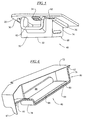
flavor insert device 40 is illustrated. In this embodiment, theflavor insert device 40 includes acup 60 comprising a container having a hollow body. Thecup 60 has aflange 62 extending around at least a portion of a periphery of the cup. Aporous enclosure 64 in the form of a porous bag is located in thecup 60. Thebag 64 may be similar in construction to thebag 46 described above. A supply ofsolid flavor particles 66 is contained in theporous bag 64. In this embodiment, thecup 60 includes awater inlet 68 and awater outlet 70. Aremovable seal 72 is provided to cover thewater inlet 68 and thewater outlet 70. Thecup 60 may be formed from a variety of materials, and in a preferred embodiment, it is formed of a plastic, such as polyethylene. - In an embodiment as illustrated, the
water inlet 68 and thewater outlet 70 are coextensive and a singleremovable seal 72 covers both the inlet and outlet. When thewater inlet 68 and thewater outlet 70 are separate openings,separate seals 72 will be required. - In the illustrated embodiment, the
cup 60 has a generally cubic rectangular shape withupstanding side walls 74, aback wall 76, afront wall 78 and abottom wall 80. As illustrated in FIG. 7, thebottom wall 80 may slope downwardly from theback wall 76 to thefront wall 78. Theside walls 74, theback wall 76 and thebottom wall 80 are generally planar and smoothly connect with each other along liquid impervious joints. Thefront wall 78 is configured to have aspout 82 which defines thewater outlet 70. Thespout 82 comprises a necked down opening from the hollow interior of thecup 60 in that the spout includesshort side walls 84 and ashort bottom wall 86 leading to thewater outlet 70 at the front side of the cup. Theflange 62 extends around the entire periphery of thewater outlet 70 and thewater inlet 68, which are coextensive. - The
seal 72 may be a foil seal, such as a lamination of aluminum foil and polyethylene, which can be applied to theflange 62 of thecup 60 by a well known induction or conduction heating process when the cup is formed of a plastic material. The polyethylene side is placed in contact with the container. When heat is applied, the polyethylene melts and bonds to thepolyethylene cup 60. The use of aseal 72 provides that the flavor insert device is a sealed capsule, and no further special handling or use of specially sealed containers is required. Theseal 72 can easily be removed from theflange 62 of thecup 60 by a manual grasping of atab 87 and removal of the seal. - On the interior of the
cup 60, retainingwalls 88, such as ribs, may be arranged to receive and secure theporous bag 64 within the cup. In the arrangement illustrated, thefront wall 78 also provides a short step at the front of thebottom wall 80 to prevent theporous bag 64 from sliding out of thecup 60 towards thespout 82. Theporous bag 64 may also be held in thecup 60 simply by a press fit with thesidewalls 74 which then act as retaining walls, or by a heat stake between the porous bag material and one or more of thewalls - To use this embodiment, the user selects a
flavor insert device 40 of a desired flavor. Once aflavor insert device 40 is selected, theprotective seal 72 is removed. Theflavor insert device 40 is then inserted into thewater dispenser 20 by sliding theflange 62 of thecup 60 or the cup itself, if not provided with a flange, onto theflange support 36 of thewater dispenser 20. This will position theflavor insert device 40 directly below thewater outlet 34 and above thereceptacle 32. In the embodiment illustrated in FIGs. 5-10, the position of theflavor insert device 40 relative to thewater dispenser 20 will be determined by a continuation of theflange support 36 across the back of the flavor insert device receiving area to provide a stop against further movement in the insertion direction. An alternative embodiment is illustrated in FIGs. 11 and 12 in which theflavor insert device 40 is identical in all respects to the embodiment shown in FIGs. 5-10, with the single exception that stoptabs 90 are formed on theflange 62, which stop tabs will engage with theflange support 36 when theflavor insert device 40 is fully inserted into position. This arrangement can be used to avoid the necessity of having the flange support or other stop arrangement extend across the back of the flavor insert device receiving area. In all other respects, the flavor insert devices shown in FIGs. 5-10 and in FIGs. 11-12 are used in an identical manner. - When water is dispensed from the
water outlet 34, it will enter thewater inlet 68 and will flow into theporous bag 64 containing thesolid flavor particles 66. Thesesolid particles 66, which may be in the form of crystals or powder, will then dissolve into the water and will flow out of theporous bag 64 to flow through thespout 82 of thecup 60 and into thereceptacle 32 as flavored water. - After the flavored water is completely dispensed, the
receptacle 32 is removed and theflavor insert device 40 is disposed of. There is no mess to clean up since any residual mixture of flavor particles and water is contained within theflavor insert device 40. An endless variety of flavors are available to the user through the selection of an appropriateflavor insert device 40. If no additional flavor is desired, theflavor insert device 40 is not inserted into thedispenser 20, and the water will flow directly from thewater outlet 34 and into thereceptacle 32 without any hindrance since theflange support 36 is positioned laterally away from the water outlet. - In FIG. 13 a fourth embodiment of a
flavor insert device 40 is illustrated. In this embodiment, theflavor insert device 40 is formed nearly identical to thecup 60 described above, with the exception that a sump or well 92 is formed in thebottom wall 80 of the cup. The supply of solid flavor particles are received in the well 92, and the well is then covered with aporous material 94 to form a porous enclosure within the flavor insert device. The porous material (of any of the types described above) may be heat staked to thebottom wall 80 surrounding thewell 92. As described above with respect to FIGs. 6 and 7, aremovable seal 72 is provided to cover thewater inlet 68 and thewater outlet 70. Thecup 60 may be formed from a variety of materials, and in a preferred embodiment, it is formed of a plastic, such as polyethylene.
Claims (10)
- A water dispenser, comprising:a housing for said dispenser,a dispensing area associated with said housing and including and space for receiving a receptacle for receiving a charge of water from said dispenser,a water outlet through which water is dispensed into said dispensing area,a fixed flange support positioned between said water outlet and said dispensing area arranged to receive a flavor insert device in a substantially horizontally sliding manner.
- A water dispenser according to claim 1, wherein said water dispenser is located in a door of a refrigeration appliance.
- A water dispenser according to claim 1, wherein said water dispenser is a stand alone appliance.
- A water dispenser according to claim 1, 2 or 3 wherein said space comprises a recess in said housing.
- A flavor insert device comprising:a cup having a flange extending around at least a portion of a periphery of said cup,a porous enclosure located in said cup anda supply of solid flavor particles contained in said porous enclosure.
- A flavor insert device according to claim 5, wherein said cup is perforated.
- A flavor insert device according to claim 5 or 6 wherein said cup is formed from polyethylene.
- A flavor insert device according to claim 5, 6 or 7, including a supply container for receiving a plurality of flavor inserts, said supply container having a moisture impervious body and a removable lid sealable to said body in a moisture impervious manner.
- A flavor insert device according to claim 5, 6, 7 or 8 wherein said cup includes a water inlet and water outlet and further including a removable seal covering said water inlet and a removable seal covering said water outlet.
- A flavor insert device according to claim 9, wherein said water inlet and said water outlet are coextensive and a single removable seal covers said inlet and outlet.
Applications Claiming Priority (1)
| Application Number | Priority Date | Filing Date | Title |
|---|---|---|---|
| US11/027,124 US7472643B2 (en) | 2004-12-31 | 2004-12-31 | Disposable flavor insert for water dispenser |
Publications (3)
| Publication Number | Publication Date |
|---|---|
| EP1676508A2 true EP1676508A2 (en) | 2006-07-05 |
| EP1676508A3 EP1676508A3 (en) | 2006-07-12 |
| EP1676508B1 EP1676508B1 (en) | 2008-09-03 |
Family
ID=36013627
Family Applications (1)
| Application Number | Title | Priority Date | Filing Date |
|---|---|---|---|
| EP05257484A Ceased EP1676508B1 (en) | 2004-12-31 | 2005-12-06 | Water dispenser with disposable flavor insert |
Country Status (4)
| Country | Link |
|---|---|
| US (3) | US7472643B2 (en) |
| EP (1) | EP1676508B1 (en) |
| CA (1) | CA2528807A1 (en) |
| DE (1) | DE602005009474D1 (en) |
Cited By (1)
| Publication number | Priority date | Publication date | Assignee | Title |
|---|---|---|---|---|
| WO2016008676A1 (en) * | 2014-07-16 | 2016-01-21 | BSH Hausgeräte GmbH | Domestic refrigeration appliance comprising a water dispenser unit that includes a receiving unit for inserting a flavor container |
Families Citing this family (60)
| Publication number | Priority date | Publication date | Assignee | Title |
|---|---|---|---|---|
| US20110020508A1 (en) | 2007-04-05 | 2011-01-27 | Rising Phoenix Co. | Select Serving and Flavored Sparkling Beverage Maker |
| US8677888B2 (en) * | 2007-04-05 | 2014-03-25 | Primo Products, LLC | Select serving and flavored sparkling beverage maker |
| WO2008124851A1 (en) * | 2007-04-05 | 2008-10-16 | Carl Santoiemmo | Select serving and flavored sparkling beverage maker |
| US20090188938A1 (en) * | 2008-01-24 | 2009-07-30 | Jeffrey Blaine Farris | Apparatus for dispensing flavors in specified quantities |
| US8359969B2 (en) * | 2008-03-31 | 2013-01-29 | Whirlpool Corporation | Apparatus, method and kit for retrofitting an indoor water dispenser of an existing refrigerator |
| JP5405168B2 (en) * | 2008-04-01 | 2014-02-05 | ホシザキ電機株式会社 | Ice making unit of a flow-down type ice machine |
| US9556011B2 (en) * | 2008-05-29 | 2017-01-31 | Whirlpool Corporation | Apparatuses and methods for a refrigerator having liquid conditioning and enhancement components for enhanced beverage dispensing |
| US9981839B2 (en) * | 2008-05-29 | 2018-05-29 | Whirlpool Corporation | Apparatuses and methods for a refrigerator having liquid conditioning and enhancement components for enhanced beverage dispensing |
| PE20110784A1 (en) | 2008-08-29 | 2011-10-27 | Pepsico Inc | POST-MIXING DRINK SYSTEM |
| US9272827B2 (en) | 2008-08-29 | 2016-03-01 | Pepsico, Inc. | Post-mix beverage system |
| US8166868B2 (en) * | 2008-12-18 | 2012-05-01 | Whirlpool Corporation | Liquid flow control and beverage preparation apparatus |
| US8166867B2 (en) * | 2008-12-18 | 2012-05-01 | Whirlpool Corporation | Liquid flow control through a beverage preparation apparatus |
| KR200450676Y1 (en) * | 2010-06-22 | 2010-10-21 | 컨벡스코리아(주) | Receptacles for Coffee Capsules |
| USD649390S1 (en) | 2010-09-02 | 2011-11-29 | Primo Products, LLC | Beverage maker |
| US9062912B2 (en) * | 2010-10-29 | 2015-06-23 | Whirlpool Corporation | Multi-single serve beverage dispensing apparatus, method and system |
| PL2637532T3 (en) * | 2010-11-09 | 2016-07-29 | La Vit Tech Llc | Capsule based system for preparing and dispensing a beverage |
| ES2842407T3 (en) | 2010-12-22 | 2021-07-14 | Syqe Medical Ltd | Drug delivery system |
| US9161654B2 (en) | 2012-03-09 | 2015-10-20 | Primo Products Llc | Select serving and flavored sparkling beverage maker system |
| CN107529427A (en) * | 2013-05-10 | 2018-01-02 | 竹斯柔公司 | Squeeze the juice system |
| DE102014012314A1 (en) * | 2014-05-30 | 2015-12-03 | Liebherr-Hausgeräte Ochsenhausen GmbH | Fridge and / or freezer |
| WO2016001925A1 (en) | 2014-06-30 | 2016-01-07 | Syqe Medical Ltd. | Drug dose cartridge for an inhaler device |
| RU2721064C2 (en) | 2014-06-30 | 2020-05-15 | Сике Медикал Лтд. | Flow-controlled inhaler |
| US11298477B2 (en) | 2014-06-30 | 2022-04-12 | Syqe Medical Ltd. | Methods, devices and systems for pulmonary delivery of active agents |
| US9580288B2 (en) * | 2014-09-05 | 2017-02-28 | Dianna Ploss | Water dispenser cover |
| EP3267857B1 (en) * | 2015-03-12 | 2019-01-23 | BSH Hausgeräte GmbH | Mixed beverage unit |
| US9883766B2 (en) * | 2015-11-20 | 2018-02-06 | Pepsico, Inc. | Beverage dispenser systems and methods |
| AU2017204945B2 (en) | 2016-01-06 | 2022-11-10 | Syqe Medical Ltd. | Low dose therapeutic treatment |
| US10464797B2 (en) | 2016-01-15 | 2019-11-05 | Pepsico, Inc. | Post-mix beverage system |
| US20170119200A1 (en) * | 2016-01-19 | 2017-05-04 | Anthony David Bressi | Automated beverage and fragrance synthesizers |
| US20170252990A1 (en) * | 2016-03-03 | 2017-09-07 | Juicero, Inc. | Juicer cartridge geometry |
| US20170252995A1 (en) * | 2016-03-03 | 2017-09-07 | Juicero, Inc. | Juicer cartridge with outlet separator |
| US20170251863A1 (en) * | 2016-03-03 | 2017-09-07 | Juicero, Inc. | Angled juicing system |
| US20170253000A1 (en) * | 2016-03-03 | 2017-09-07 | Juicero, Inc. | Juicer with locking mechanism |
| US20170252998A1 (en) * | 2016-03-03 | 2017-09-07 | Juicero, Inc. | Juicer cartridge with flow disruptor |
| US20170252993A1 (en) * | 2016-03-03 | 2017-09-07 | Juicero, Inc. | Juicer cartridge with coupling |
| US20170252997A1 (en) * | 2016-03-03 | 2017-09-07 | Juicero, Inc. | Juicer cartridge with sanitary seal |
| US20170252999A1 (en) * | 2016-03-03 | 2017-09-07 | Juicero, Inc. | Juicer with juicer cartridge orientation feature |
| US20170252996A1 (en) * | 2016-03-03 | 2017-09-07 | Juicero, Inc. | Juicer cartridge with secondary flow channel |
| US20170252991A1 (en) * | 2016-03-03 | 2017-09-07 | Juicero, Inc. | Juicer with flexible seal |
| US10610045B2 (en) | 2016-06-14 | 2020-04-07 | Pepsico, Inc. | Beverage system including a removable piercer |
| CA3041722A1 (en) | 2016-11-09 | 2018-05-17 | Pepsico, Inc. | Carbonated beverage makers, methods, and systems |
| CN107928408A (en) * | 2017-10-13 | 2018-04-20 | 青岛海尔股份有限公司 | Refrigerator |
| CN119403454A (en) | 2022-05-13 | 2025-02-07 | 尚科宁家运营有限公司 | Agitators for carbonation systems |
| US12213617B2 (en) | 2022-05-13 | 2025-02-04 | Sharkninja Operating Llc | Flavored beverage carbonation process |
| US11751585B1 (en) | 2022-05-13 | 2023-09-12 | Sharkninja Operating Llc | Flavored beverage carbonation system |
| US12096880B2 (en) | 2022-05-13 | 2024-09-24 | Sharkninja Operating Llc | Flavorant for beverage carbonation system |
| US11647860B1 (en) | 2022-05-13 | 2023-05-16 | Sharkninja Operating Llc | Flavored beverage carbonation system |
| US12005404B2 (en) | 2022-08-22 | 2024-06-11 | Sharkninja Operating Llc | Beverage carbonation system flow control |
| US12539500B2 (en) | 2022-08-31 | 2026-02-03 | Sharkninja Operating Llc | Additive containers |
| US11745996B1 (en) | 2022-11-17 | 2023-09-05 | Sharkninja Operating Llc | Ingredient containers for use with beverage dispensers |
| US12084334B2 (en) | 2022-11-17 | 2024-09-10 | Sharkninja Operating Llc | Ingredient container |
| US11634314B1 (en) | 2022-11-17 | 2023-04-25 | Sharkninja Operating Llc | Dosing accuracy |
| US11738988B1 (en) | 2022-11-17 | 2023-08-29 | Sharkninja Operating Llc | Ingredient container valve control |
| US12103840B2 (en) | 2022-11-17 | 2024-10-01 | Sharkninja Operating Llc | Ingredient container with sealing valve |
| USD1092208S1 (en) | 2022-12-23 | 2025-09-09 | Sharkninja Operating Llc | Cap of ingredient container |
| USD1091308S1 (en) | 2022-12-23 | 2025-09-02 | Sharkninja Operating Llc | Ingredient container |
| US11871867B1 (en) | 2023-03-22 | 2024-01-16 | Sharkninja Operating Llc | Additive container with bottom cover |
| US11925287B1 (en) | 2023-03-22 | 2024-03-12 | Sharkninja Operating Llc | Additive container with inlet tube |
| US12116257B1 (en) | 2023-03-22 | 2024-10-15 | Sharkninja Operating Llc | Adapter for beverage dispenser |
| US12005408B1 (en) | 2023-04-14 | 2024-06-11 | Sharkninja Operating Llc | Mixing funnel |
Citations (4)
| Publication number | Priority date | Publication date | Assignee | Title |
|---|---|---|---|---|
| US3292527A (en) | 1963-03-04 | 1966-12-20 | Stasse Roland | Apparatus for preparing and dispensing beverages from prefabricated cartridges and aliquid |
| US4996066A (en) | 1989-05-15 | 1991-02-26 | Hag Gf Aktiengesellschaft | Beverage flavoring cassette |
| US5766453A (en) | 1995-11-13 | 1998-06-16 | Whirlpool Corporation | Filtered water dispensing cabinet |
| US6672097B1 (en) | 2003-02-28 | 2004-01-06 | Josh Ashley | Flavored ice cartridge dispenser for ice maker |
Family Cites Families (38)
| Publication number | Priority date | Publication date | Assignee | Title |
|---|---|---|---|---|
| US2283967A (en) * | 1940-10-10 | 1942-05-26 | William F Brown | Beverage apparatus |
| US2551219A (en) * | 1947-02-27 | 1951-05-01 | Cory Corp | Beverage brewer |
| US2589783A (en) * | 1948-04-09 | 1952-03-18 | Cory Corp | Beverage brewer |
| US2743664A (en) * | 1952-01-23 | 1956-05-01 | Cory Corp | Disposable coffee brewer |
| US3295998A (en) * | 1962-05-28 | 1967-01-03 | Vendcor Inc | Apparatus for preparing and dispensing hot potables |
| US3260190A (en) * | 1963-09-23 | 1966-07-12 | David J Levinson | Equipment adaptable to brewing coffee in the original sealed container |
| US3445237A (en) * | 1966-06-28 | 1969-05-20 | Lester Gidge | Preshaped cartridge for,and method of packaging,percolator ground coffee |
| US3450024A (en) * | 1968-06-17 | 1969-06-17 | Bunn O Matic Corp | Coffee making machine with holder for prepackaged ground coffee |
| SE378409B (en) * | 1968-12-18 | 1975-09-01 | Kantor Int Sa | |
| US4808346A (en) * | 1972-07-20 | 1989-02-28 | Strenger & Associates | Carbonated beverage dispensing apparatus and method |
| BE790706A (en) | 1972-10-30 | 1973-02-15 | Miko N V | DISPOSABLE FILTER PACK, RESPECTIVE CARTRIDGE, FOR PREPARING COFFEE BREED. |
| IT1194662B (en) * | 1980-06-11 | 1988-09-22 | Giuseppe Stefano Piana | MACHINE FOR THE PREPARATION OF ESPRESSO COFFEE, CAPPUCCINO, TEA, BROTH OR OTHER INFUSIONS, AUTOMATICALLY OPERATED, BY A DISPOSABLE FILTER, CONTAINING ONE OR MORE DOSES OF PRODUCTS, INTRODUCED AS A COIN |
| AU553684B2 (en) * | 1980-12-27 | 1986-07-24 | Kataoka Bussan K.K. | Coffee package |
| US4382402A (en) * | 1981-04-01 | 1983-05-10 | Alvarez Donald E | Portable coffee maker |
| US4708266A (en) * | 1986-03-21 | 1987-11-24 | The Coca-Cola Company | Concentrate dispensing system for a post-mix beverage dispenser |
| FR2617389B1 (en) | 1987-06-30 | 1991-05-24 | Desaltera | FILTER CARTRIDGE AND MACHINE FOR THE PREPARATION OF AN EXPRESS BEVERAGE |
| NL8701627A (en) | 1987-07-10 | 1989-02-01 | Douwe Egberts Tabaksfab | Coffee filter universal container - is constructed with tapered stepped holder and filter paper insert |
| US4867993A (en) | 1988-02-08 | 1989-09-19 | Nordskog Robert A | Disposable beverage brewing chamber |
| US4921712A (en) * | 1988-08-19 | 1990-05-01 | Malmquist Neil A | Automatic low volume beverage brewing system |
| US4975292A (en) | 1989-01-26 | 1990-12-04 | Loizzi Carl J | Flavored inserts for coffee filters or the like |
| CA1269690A (en) * | 1989-03-14 | 1990-05-29 | Peter Klein | Electrical apparatus useful to prepare a hot beverage |
| US5243164A (en) * | 1990-12-14 | 1993-09-07 | Gee Associates | Beverage maker |
| US5567461A (en) | 1994-05-09 | 1996-10-22 | Robert Lehrer Associates, Inc. | Method of treating fluids with a filter |
| US5498757A (en) * | 1995-04-04 | 1996-03-12 | Boyd Coffee Company | Milk frothing and heating system |
| US5865094A (en) * | 1996-02-13 | 1999-02-02 | Kealy; Michael J. | Filtered beverage maker |
| DE19609561A1 (en) * | 1996-03-12 | 1997-09-18 | Braun Ag | Coffee machine and filter element for this |
| US5836169A (en) * | 1997-01-29 | 1998-11-17 | Marlette; Todd E. | Coffee brewer including refrigerated storage receptacle |
| US6260476B1 (en) * | 1999-08-06 | 2001-07-17 | Bunn-O-Matic Corporation | Beverage brewing substance holder |
| CA2325978A1 (en) | 1999-11-16 | 2001-05-16 | Robert Hale | Beverage filter cartridge system |
| US6896159B2 (en) * | 2000-06-08 | 2005-05-24 | Beverage Works, Inc. | Beverage dispensing apparatus having fluid director |
| US6357342B1 (en) * | 2000-09-11 | 2002-03-19 | Simatelex Manufactory Co., Ltd. | Electric coffee maker |
| US6740345B2 (en) * | 2000-12-22 | 2004-05-25 | Edward Zhihua Cai | Beverage making cartridge |
| US6606938B2 (en) * | 2001-04-06 | 2003-08-19 | Keurig, Incorporated | Two step puncturing and venting of single serve filter cartridge in a beverage brewer |
| US6698228B2 (en) * | 2001-11-02 | 2004-03-02 | Moobella, Llc | Method and apparatus for producing and dispensing an aerated and/or blended food product |
| US20060289253A1 (en) * | 2005-06-23 | 2006-12-28 | Kelsey-Hayes Company | Monoblock caliper housing for a disc brake assembly |
| US7444926B2 (en) * | 2003-09-09 | 2008-11-04 | Nottingham John R | Apparatus for brewing and method for making the same |
| US7017472B2 (en) * | 2003-10-10 | 2006-03-28 | Hp Intellectual Corp. | Brewing apparatus water temperature control |
| US7673556B2 (en) * | 2004-07-19 | 2010-03-09 | Spencer William L | Coffee maker and method of use |
-
2004
- 2004-12-31 US US11/027,124 patent/US7472643B2/en active Active
-
2005
- 2005-12-01 CA CA002528807A patent/CA2528807A1/en not_active Abandoned
- 2005-12-06 EP EP05257484A patent/EP1676508B1/en not_active Ceased
- 2005-12-06 DE DE602005009474T patent/DE602005009474D1/en not_active Expired - Lifetime
-
2008
- 2008-08-21 US US12/195,494 patent/US8555774B2/en not_active Expired - Fee Related
-
2013
- 2013-10-15 US US14/053,759 patent/US20140037794A1/en not_active Abandoned
Patent Citations (4)
| Publication number | Priority date | Publication date | Assignee | Title |
|---|---|---|---|---|
| US3292527A (en) | 1963-03-04 | 1966-12-20 | Stasse Roland | Apparatus for preparing and dispensing beverages from prefabricated cartridges and aliquid |
| US4996066A (en) | 1989-05-15 | 1991-02-26 | Hag Gf Aktiengesellschaft | Beverage flavoring cassette |
| US5766453A (en) | 1995-11-13 | 1998-06-16 | Whirlpool Corporation | Filtered water dispensing cabinet |
| US6672097B1 (en) | 2003-02-28 | 2004-01-06 | Josh Ashley | Flavored ice cartridge dispenser for ice maker |
Cited By (1)
| Publication number | Priority date | Publication date | Assignee | Title |
|---|---|---|---|---|
| WO2016008676A1 (en) * | 2014-07-16 | 2016-01-21 | BSH Hausgeräte GmbH | Domestic refrigeration appliance comprising a water dispenser unit that includes a receiving unit for inserting a flavor container |
Also Published As
| Publication number | Publication date |
|---|---|
| US8555774B2 (en) | 2013-10-15 |
| CA2528807A1 (en) | 2006-06-30 |
| EP1676508B1 (en) | 2008-09-03 |
| US20060144242A1 (en) | 2006-07-06 |
| EP1676508A3 (en) | 2006-07-12 |
| US20140037794A1 (en) | 2014-02-06 |
| DE602005009474D1 (en) | 2008-10-16 |
| US7472643B2 (en) | 2009-01-06 |
| US20080302123A1 (en) | 2008-12-11 |
Similar Documents
| Publication | Publication Date | Title |
|---|---|---|
| US7472643B2 (en) | Disposable flavor insert for water dispenser | |
| US4800089A (en) | Packet with internal filter for coffee machines | |
| EP1322208B1 (en) | Coffee maker | |
| CN103987300B (en) | For the drip tray of beverage dispenser | |
| KR101173173B1 (en) | Coffee infusion press for stackable cups | |
| US7258884B2 (en) | Method employing a disposable brew basket for an electric coffee maker | |
| EP1631176B1 (en) | A brewing receptacle and a foam unit and a beverage maker comprising such a brewing receptacle | |
| US7845509B2 (en) | Lid for a beverage container to hold a decoction beverage | |
| US4921712A (en) | Automatic low volume beverage brewing system | |
| KR101845219B1 (en) | Method for preparing a beverage from a capsule, capsule and beverage preparing system | |
| BRPI0615858A2 (en) | cartridge for extracting a beverage from an edible substance contained therein, and extraction assembly for mounting on beverage extraction machines | |
| CN111317326A (en) | Liquid container cap assembly | |
| CN105792711A (en) | Device and method for brewing a beverage | |
| JPH01274719A (en) | Disposable beverage control chamber | |
| AU2001289907A1 (en) | Coffee maker | |
| US5906844A (en) | Coffee maker | |
| JP2000229698A (en) | Refill cartridge for beverage dispensing device and device for the cartridge | |
| CN104853996B (en) | Disposable brewing device and use of the disposable brewing device | |
| CN101801248A (en) | Cartridges of infusible substances for infusing beverages | |
| JP2007503274A5 (en) | ||
| JPH034816A (en) | improved coffee cassette | |
| GB2241696A (en) | Solids dispenser, e.g. for ice cubes | |
| EP0716031A2 (en) | Flavouring devices and methods | |
| KR101070788B1 (en) | Unit for separating receptacle and apparatus for supplying drinking water | |
| KR20170079453A (en) | A juicer with push type vacuum system |
Legal Events
| Date | Code | Title | Description |
|---|---|---|---|
| PUAI | Public reference made under article 153(3) epc to a published international application that has entered the european phase |
Free format text: ORIGINAL CODE: 0009012 |
|
| PUAL | Search report despatched |
Free format text: ORIGINAL CODE: 0009013 |
|
| AK | Designated contracting states |
Kind code of ref document: A2 Designated state(s): AT BE BG CH CY CZ DE DK EE ES FI FR GB GR HU IE IS IT LI LT LU LV MC NL PL PT RO SE SI SK TR |
|
| AX | Request for extension of the european patent |
Extension state: AL BA HR MK YU |
|
| AK | Designated contracting states |
Kind code of ref document: A3 Designated state(s): AT BE BG CH CY CZ DE DK EE ES FI FR GB GR HU IE IS IT LI LT LU LV MC NL PL PT RO SE SI SK TR |
|
| AX | Request for extension of the european patent |
Extension state: AL BA HR MK YU |
|
| 17P | Request for examination filed |
Effective date: 20060818 |
|
| 17Q | First examination report despatched |
Effective date: 20060921 |
|
| AKX | Designation fees paid |
Designated state(s): DE FR IT |
|
| GRAP | Despatch of communication of intention to grant a patent |
Free format text: ORIGINAL CODE: EPIDOSNIGR1 |
|
| RAP1 | Party data changed (applicant data changed or rights of an application transferred) |
Owner name: WHIRLPOOL CORPORATION |
|
| GRAS | Grant fee paid |
Free format text: ORIGINAL CODE: EPIDOSNIGR3 |
|
| GRAA | (expected) grant |
Free format text: ORIGINAL CODE: 0009210 |
|
| AK | Designated contracting states |
Kind code of ref document: B1 Designated state(s): DE FR IT |
|
| REF | Corresponds to: |
Ref document number: 602005009474 Country of ref document: DE Date of ref document: 20081016 Kind code of ref document: P |
|
| PLBE | No opposition filed within time limit |
Free format text: ORIGINAL CODE: 0009261 |
|
| STAA | Information on the status of an ep patent application or granted ep patent |
Free format text: STATUS: NO OPPOSITION FILED WITHIN TIME LIMIT |
|
| 26N | No opposition filed |
Effective date: 20090604 |
|
| REG | Reference to a national code |
Ref country code: FR Ref legal event code: PLFP Year of fee payment: 11 |
|
| REG | Reference to a national code |
Ref country code: FR Ref legal event code: PLFP Year of fee payment: 12 |
|
| REG | Reference to a national code |
Ref country code: FR Ref legal event code: PLFP Year of fee payment: 13 |
|
| PGFP | Annual fee paid to national office [announced via postgrant information from national office to epo] |
Ref country code: DE Payment date: 20171129 Year of fee payment: 13 Ref country code: FR Payment date: 20171113 Year of fee payment: 13 |
|
| PGFP | Annual fee paid to national office [announced via postgrant information from national office to epo] |
Ref country code: IT Payment date: 20171221 Year of fee payment: 13 |
|
| REG | Reference to a national code |
Ref country code: DE Ref legal event code: R119 Ref document number: 602005009474 Country of ref document: DE |
|
| PG25 | Lapsed in a contracting state [announced via postgrant information from national office to epo] |
Ref country code: FR Free format text: LAPSE BECAUSE OF NON-PAYMENT OF DUE FEES Effective date: 20181231 Ref country code: IT Free format text: LAPSE BECAUSE OF NON-PAYMENT OF DUE FEES Effective date: 20181206 Ref country code: DE Free format text: LAPSE BECAUSE OF NON-PAYMENT OF DUE FEES Effective date: 20190702 |