EP1675198A1 - Battery-holder assembly for a vehicle, especially an industrial vehicle - Google Patents
Battery-holder assembly for a vehicle, especially an industrial vehicle Download PDFInfo
- Publication number
- EP1675198A1 EP1675198A1 EP05110879A EP05110879A EP1675198A1 EP 1675198 A1 EP1675198 A1 EP 1675198A1 EP 05110879 A EP05110879 A EP 05110879A EP 05110879 A EP05110879 A EP 05110879A EP 1675198 A1 EP1675198 A1 EP 1675198A1
- Authority
- EP
- European Patent Office
- Prior art keywords
- box
- battery
- holder assembly
- vehicle
- plate
- Prior art date
- Legal status (The legal status is an assumption and is not a legal conclusion. Google has not performed a legal analysis and makes no representation as to the accuracy of the status listed.)
- Granted
Links
Images


Classifications
-
- H—ELECTRICITY
- H01—ELECTRIC ELEMENTS
- H01M—PROCESSES OR MEANS, e.g. BATTERIES, FOR THE DIRECT CONVERSION OF CHEMICAL ENERGY INTO ELECTRICAL ENERGY
- H01M50/00—Constructional details or processes of manufacture of the non-active parts of electrochemical cells other than fuel cells, e.g. hybrid cells
- H01M50/20—Mountings; Secondary casings or frames; Racks, modules or packs; Suspension devices; Shock absorbers; Transport or carrying devices; Holders
- H01M50/204—Racks, modules or packs for multiple batteries or multiple cells
- H01M50/207—Racks, modules or packs for multiple batteries or multiple cells characterised by their shape
- H01M50/209—Racks, modules or packs for multiple batteries or multiple cells characterised by their shape adapted for prismatic or rectangular cells
-
- H—ELECTRICITY
- H01—ELECTRIC ELEMENTS
- H01M—PROCESSES OR MEANS, e.g. BATTERIES, FOR THE DIRECT CONVERSION OF CHEMICAL ENERGY INTO ELECTRICAL ENERGY
- H01M50/00—Constructional details or processes of manufacture of the non-active parts of electrochemical cells other than fuel cells, e.g. hybrid cells
- H01M50/20—Mountings; Secondary casings or frames; Racks, modules or packs; Suspension devices; Shock absorbers; Transport or carrying devices; Holders
- H01M50/296—Mountings; Secondary casings or frames; Racks, modules or packs; Suspension devices; Shock absorbers; Transport or carrying devices; Holders characterised by terminals of battery packs
-
- Y—GENERAL TAGGING OF NEW TECHNOLOGICAL DEVELOPMENTS; GENERAL TAGGING OF CROSS-SECTIONAL TECHNOLOGIES SPANNING OVER SEVERAL SECTIONS OF THE IPC; TECHNICAL SUBJECTS COVERED BY FORMER USPC CROSS-REFERENCE ART COLLECTIONS [XRACs] AND DIGESTS
- Y02—TECHNOLOGIES OR APPLICATIONS FOR MITIGATION OR ADAPTATION AGAINST CLIMATE CHANGE
- Y02E—REDUCTION OF GREENHOUSE GAS [GHG] EMISSIONS, RELATED TO ENERGY GENERATION, TRANSMISSION OR DISTRIBUTION
- Y02E60/00—Enabling technologies; Technologies with a potential or indirect contribution to GHG emissions mitigation
- Y02E60/10—Energy storage using batteries
Definitions
- This invention relates to improvements to a battery-holder assembly for a vehicle, especially an industrial vehicle.
- the purpose of this invention is to overcome the drawbacks described above with improvements to a battery-holder assembly for a vehicle, especially an industrial vehicle, in order to guarantee protection against short-circuits between "hot” cables on the frame, reduce the number of positive cables in the area around the battery box, improve accessibility from the ground to the poles of the battery, improve the passage of "hot” cables on the frame.
- this invention relates to improvements to a battery-holder assembly for a vehicle, especially an industrial vehicle, as described more fully in the claims, which are an integral part of this description.
- a battery box 1 fixed laterally to a frame side member 2 of the vehicle.
- the box 1 houses one or more batteries (two are visible in the drawings, 3-1 and 3-2), arranged at right angles to the frame side member, and thus to the vehicle frame, in order to optimize the use of space and make it easier to access the hot (positive "+”) terminals of the batteries.
- the batteries may however also be arranged so that they are parallel to the frame side member
- An electrical plate 6 is mounted on the side of the battery box 1 and receives the positive voltage from the battery, via the through-wall pin 5, or the positive voltage downstream of the battery disconnector, according to the wiring diagrams as described below with reference to figures 3a and 3b.
- the plate 6 consists of a terminal plate made of tinned copper or brass, that is attached to the battery box by means of insulating screws (for example M6 standard).
- the various electrical cables are fastened to the plate 6 by means of anti-rotation terminals 14 (for example as illustrated in fig. 4b) so that the electrical cables are substantially parallel to the ground.
- the electrical cables may be prevented from rotating by means of projecting parts 16 on the plate 6 at the sides of the cable positions (11, 15).
- the plate 6 may be equipped with a protective cover that encloses the plate completely.
- One or more fuse boxes 7 and a disconnecting switch 8 are attached to a bracket 10 that is in turn mounted on the side wall of the box 1 so as to project from said wall.
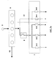
- FIG. 3a An example of the electrical connections between the various elements is shown in figure 3a. From the through-wall pin 5 the positive voltage is carried to the plate 6. There may be an electrical connection 15 from the plate 6 directly to the devices to be powered without passing through the fuse box 7. There may be a direct electrical connection 11 from the plate 6 to one or more fuses in the box 7, for example 9-4 and 9-5. There may be an electrical connection from the plate 6 to other fuses in the box 7, for example 9-1, 9-2 and 9-3, via the disconnector 8, that can be used to disconnect the electrical connection towards the devices of the vehicle powered via these fuses, for example for maintenance purposes.
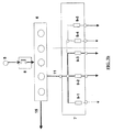
- FIG 3b An example of an alternative arrangement of the electrical connections between the various elements is illustrated in figure 3b, in which, compared to figure 3a, the positions of the disconnecting switch 8 and the plate 6 are reversed. From the through-wall pin 5 the positive voltage is carried to the plate 6 that distributes it either to the fuse boxes 7 or directly to the devices to be powered by means of the electrical connection 15.
- the disconnecting switch 8 may be of the mechanical switch or lever type, or of the electrical/electronic type.
- the fuse box 7 may be a single box or divided into sections, for example with one part containing non-disconnectable fuses, and another for disconnectable fuses, or there may be several separate boxes.
- sub-assemblies comprising respectively:
Landscapes
- Chemical & Material Sciences (AREA)
- Chemical Kinetics & Catalysis (AREA)
- Electrochemistry (AREA)
- General Chemical & Material Sciences (AREA)
- Battery Mounting, Suspending (AREA)
- Arrangement Or Mounting Of Propulsion Units For Vehicles (AREA)
- Connection Of Batteries Or Terminals (AREA)
Abstract
Description
- This invention relates to improvements to a battery-holder assembly for a vehicle, especially an industrial vehicle.
- Particular attention must be paid to the electrical power supply of a vehicle, especially an industrial vehicle, in order to avoid problems such as short-circuits, that may occur in situations in which the electrical current paths are exposed to the risk of corrosion or deterioration due to atmospheric factors, or accidental events, or peeling, to which cable insulation sheathing is particularly prone. Another risk factor is related to the presence of too many cables placed too close together, especially in the area around the battery box, a situation which also renders maintenance and repair operations more difficult.
- The purpose of this invention is to overcome the drawbacks described above with improvements to a battery-holder assembly for a vehicle, especially an industrial vehicle, in order to guarantee protection against short-circuits between "hot" cables on the frame, reduce the number of positive cables in the area around the battery box, improve accessibility from the ground to the poles of the battery, improve the passage of "hot" cables on the frame.
- In particular this invention relates to improvements to a battery-holder assembly for a vehicle, especially an industrial vehicle, as described more fully in the claims, which are an integral part of this description.
- The purposes and advantages of this invention will become clear from the following detailed description of an embodiment and the alternative embodiments thereof, and the drawings that are attached hereto, which are merely illustrative and not limitative, of which:
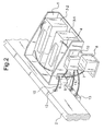
- figures 1 and 2 are front and side views respectively of a battery-holder assembly according to this invention;
- figures 3a and 3b illustrate two alternative wiring diagrams.
- figures 4a and 4b illustrate an electrical cable clamp plate and cable terminals respectively.
- The same reference numbers and letters are used in the drawings to indicate the same components.
- With reference to figures 1 and 2, there is a battery box 1, fixed laterally to a
frame side member 2 of the vehicle. The box 1 houses one or more batteries (two are visible in the drawings, 3-1 and 3-2), arranged at right angles to the frame side member, and thus to the vehicle frame, in order to optimize the use of space and make it easier to access the hot (positive "+") terminals of the batteries. - The batteries may however also be arranged so that they are parallel to the frame side member
- In order to reduce the number of positive cables inside the battery box, there is only one cable 4 connected to the positive "+" of the battery 3-1 and to an insulating through-
wall pin 5 on the side wall of the box: this means that the positive terminal is brought outside the box. The batteries are connected in series and the negative pole is connected to the vehicle's ground in a known way. - An
electrical plate 6 is mounted on the side of the battery box 1 and receives the positive voltage from the battery, via the through-wall pin 5, or the positive voltage downstream of the battery disconnector, according to the wiring diagrams as described below with reference to figures 3a and 3b. - Electrical wires leave the
plate 6 and carry the positive voltage to the other elements. - In an example of embodiment, fig. 4a, the
plate 6 consists of a terminal plate made of tinned copper or brass, that is attached to the battery box by means of insulating screws (for example M6 standard). The various electrical cables are fastened to theplate 6 by means of anti-rotation terminals 14 (for example as illustrated in fig. 4b) so that the electrical cables are substantially parallel to the ground. - Alternatively the electrical cables may be prevented from rotating by means of projecting
parts 16 on theplate 6 at the sides of the cable positions (11, 15). - The
plate 6 may be equipped with a protective cover that encloses the plate completely. - One or
more fuse boxes 7 and a disconnectingswitch 8 are attached to abracket 10 that is in turn mounted on the side wall of the box 1 so as to project from said wall. - An example of the electrical connections between the various elements is shown in figure 3a. From the through-
wall pin 5 the positive voltage is carried to theplate 6. There may be anelectrical connection 15 from theplate 6 directly to the devices to be powered without passing through thefuse box 7. There may be a directelectrical connection 11 from theplate 6 to one or more fuses in thebox 7, for example 9-4 and 9-5. There may be an electrical connection from theplate 6 to other fuses in thebox 7, for example 9-1, 9-2 and 9-3, via thedisconnector 8, that can be used to disconnect the electrical connection towards the devices of the vehicle powered via these fuses, for example for maintenance purposes. - An example of an alternative arrangement of the electrical connections between the various elements is illustrated in figure 3b, in which, compared to figure 3a, the positions of the disconnecting
switch 8 and theplate 6 are reversed. From the through-wall pin 5 the positive voltage is carried to theplate 6 that distributes it either to thefuse boxes 7 or directly to the devices to be powered by means of theelectrical connection 15. - The disconnecting
switch 8 may be of the mechanical switch or lever type, or of the electrical/electronic type. Thefuse box 7 may be a single box or divided into sections, for example with one part containing non-disconnectable fuses, and another for disconnectable fuses, or there may be several separate boxes. - In order to facilitate the connection of the cables in the
fuse box 7, the components are arranged as sub-assemblies comprising respectively: - the
fuse box 7 complete with all the electrical cables; - the
electrical disconnector 8; - the
plate 6. - Furthermore some
electrical cables 15, for example those used to supply power to devices such as the starting motor or the heater (not shown in the drawing), are not protected by fuses. These can be made to pass, directly from theplate 6, through a through-hole 12 in theframe side member 2 near the case 1. - Other cables leading out of the
fuse box 7, used to supply power to other devices, pass under theframe side member 2, and are fastened by means ofappropriate cable guides 13 connected to the longitudinal member. - It will be apparent to the person skilled in the art that other alternative and equivalent embodiments of the invention can be conceived and reduced to practice without departing from the true spirit of the invention.
- From the description set forth above it will be possible for the person skilled in the art to embody the invention without introducing any further construction details.
Claims (7)
- Improvements to a battery-holder assembly for a vehicle, especially an industrial vehicle, characterized in that said battery-holder assembly comprises:- a battery box (1), fixed laterally to a frame side member(2) of the vehicle;- one or more batteries housed in said box (3-1, 3-2) and arranged at right angles or parallel to the longitudinal member;- an electrical connection (4) that connects a "hot" pole of the batteries to the outside of the box via a through-wall pin (5) electrically insulated from the box;- one or more fuse boxes (7) and one or more disconnecting switches (8) attached to a bracket (10) that is in turn mounted on a side wall of the box (1) so as to project from said wall;- said through-wall pin (5) being connected either to said one or more disconnectors (8) or to an electrical plate (6), mounted on the side of the box (1); said plate (6) being connected electrically to said one or more fuse boxes (7) either directly or via said one or more disconnectors (8).
- Improvements to a battery-holder assembly for a vehicle according to claim 1, characterized in that said electrical plate (6) comprises a terminal plate made of tinned copper or brass, that is attached to said box (1) by means of insulating screws, electrical cables being attached to the plate by means of anti-rotation elements (14) so as to be substantially parallel to the ground.
- Improvements to a battery-holder assembly for a vehicle according to claim 1, characterized in that said electrical plate (6) comprises one or more electrical connections (15) directly to devices to be powered without passing through said fuse box (7).
- Improvements to a battery-holder assembly for a vehicle according to claim 1, characterized in that said one or more disconnectors (8) are of the mechanical switch or lever type, or of the electronic type.
- Improvements to a battery-holder assembly for a vehicle according to claim 1, characterized in that said one or more fuse boxes (7) are single, or divided into sections, comprising a part containing fuses that cannot be disconnected by means of said disconnector (8), and/or disconnectable fuses, or comprising several separate boxes.
- Improvements to a battery-holder assembly for a vehicle according to claim 1, characterized in that they comprise electrical cables that, upon leaving said one or more fuse boxes (7) or said one or more disconnectors (8), are made to pass through a through-hole (12) in said frame side member (2) near said box (1), and/or through cable guides (13) mounted on said frame said member (2).
- Improvements to a battery-holder assembly for a vehicle according to claim 1, characterized in that said anti-rotation elements consist of anti-rotation terminals (14) or projecting parts (16) on said electrical plate (6) at the sides of the cable positions.
Applications Claiming Priority (1)
| Application Number | Priority Date | Filing Date | Title |
|---|---|---|---|
| IT002471A ITMI20042471A1 (en) | 2004-12-23 | 2004-12-23 | IMPROVEMENTS TO A BATTERY HOLDER GROUP FOR VEHICLE ESPECIALLY INDUSTRIAL VEHICLE |
Publications (2)
| Publication Number | Publication Date |
|---|---|
| EP1675198A1 true EP1675198A1 (en) | 2006-06-28 |
| EP1675198B1 EP1675198B1 (en) | 2013-07-10 |
Family
ID=34956557
Family Applications (1)
| Application Number | Title | Priority Date | Filing Date |
|---|---|---|---|
| EP05110879.3A Expired - Lifetime EP1675198B1 (en) | 2004-12-23 | 2005-11-17 | Battery-holder assembly for a vehicle, especially an industrial vehicle |
Country Status (3)
| Country | Link |
|---|---|
| EP (1) | EP1675198B1 (en) |
| ES (1) | ES2429441T3 (en) |
| IT (1) | ITMI20042471A1 (en) |
Citations (4)
| Publication number | Priority date | Publication date | Assignee | Title |
|---|---|---|---|---|
| EP0662725A1 (en) * | 1994-01-06 | 1995-07-12 | Gnb Industrial Battery Company | Sealed lead-acid battery tray assemblies and motive power vehicles using such battery tray assemblies |
| WO1999036974A1 (en) * | 1998-01-19 | 1999-07-22 | Johnson Controls Technology Company | Snap-fit battery and holder |
| US6224998B1 (en) * | 1999-02-04 | 2001-05-01 | Delphi Technologies, Inc. | Battery, tray and heat shield assembly |
| US6406812B1 (en) * | 1999-04-23 | 2002-06-18 | Oldham France S.A. | Continuous current supply for electrical automotive vehicle |
-
2004
- 2004-12-23 IT IT002471A patent/ITMI20042471A1/en unknown
-
2005
- 2005-11-17 EP EP05110879.3A patent/EP1675198B1/en not_active Expired - Lifetime
- 2005-11-17 ES ES05110879T patent/ES2429441T3/en not_active Expired - Lifetime
Patent Citations (4)
| Publication number | Priority date | Publication date | Assignee | Title |
|---|---|---|---|---|
| EP0662725A1 (en) * | 1994-01-06 | 1995-07-12 | Gnb Industrial Battery Company | Sealed lead-acid battery tray assemblies and motive power vehicles using such battery tray assemblies |
| WO1999036974A1 (en) * | 1998-01-19 | 1999-07-22 | Johnson Controls Technology Company | Snap-fit battery and holder |
| US6224998B1 (en) * | 1999-02-04 | 2001-05-01 | Delphi Technologies, Inc. | Battery, tray and heat shield assembly |
| US6406812B1 (en) * | 1999-04-23 | 2002-06-18 | Oldham France S.A. | Continuous current supply for electrical automotive vehicle |
Also Published As
| Publication number | Publication date |
|---|---|
| ITMI20042471A1 (en) | 2005-03-23 |
| EP1675198B1 (en) | 2013-07-10 |
| ES2429441T3 (en) | 2013-11-14 |
Similar Documents
| Publication | Publication Date | Title |
|---|---|---|
| US7830648B2 (en) | Tap apparatus for electrically interconnecting an electrical busway and switchgear, and system including the same | |
| US6920038B2 (en) | Terminal block and renovation load center employing the same | |
| CN111326872B (en) | Conductors for power distribution systems | |
| CA2787726C (en) | Integrated safety disconnects for power systems | |
| US5206777A (en) | Three-phase panelboard using standard rated three-pole circuit protective devices in a grounded delta system | |
| US20100133078A1 (en) | Installation switching device | |
| US7173809B2 (en) | Multiphase busbar system | |
| US9124077B2 (en) | Meter socket and load center combination apparatus, electrical distribution systems, and methods of assembly | |
| CN102652388A (en) | Apparatus, system and method employing ups | |
| US20170302039A1 (en) | Load center and busway | |
| US12155182B2 (en) | Electrical equipment with additional compartment and wiring to account for temperature limitations of connected conductors | |
| US20100323236A1 (en) | Power supply apparatus | |
| TW200522112A (en) | Vacuum switchgear system | |
| US3204150A (en) | Terminal connections for circuit protective devices | |
| EP1675198B1 (en) | Battery-holder assembly for a vehicle, especially an industrial vehicle | |
| CN107706013A (en) | Manual maintenance switchs | |
| JP3638612B2 (en) | Electric drive vehicle | |
| US20130188297A1 (en) | Neutral bus for a neutral bar and electrical distribution panel including the same | |
| BR9805417B1 (en) | differential unit and process for connecting the differential unit to a circuit breaker. | |
| JPH1118216A (en) | Insulated wiring distribution board and terminal stand for back wiring | |
| JP7846542B2 (en) | wiring device | |
| KR20100061175A (en) | Junction box having battery charging terminal | |
| JPH10257613A (en) | Metal closed switchgear | |
| JPS6241523Y2 (en) | ||
| US20260018868A1 (en) | Fuse assembly for power distribution system incorporating electrically insulated connectors to conductive elements |
Legal Events
| Date | Code | Title | Description |
|---|---|---|---|
| PUAI | Public reference made under article 153(3) epc to a published international application that has entered the european phase |
Free format text: ORIGINAL CODE: 0009012 |
|
| AK | Designated contracting states |
Kind code of ref document: A1 Designated state(s): AT BE BG CH CY CZ DE DK EE ES FI FR GB GR HU IE IS IT LI LT LU LV MC NL PL PT RO SE SI SK TR |
|
| AX | Request for extension of the european patent |
Extension state: AL BA HR MK YU |
|
| 17P | Request for examination filed |
Effective date: 20061221 |
|
| AKX | Designation fees paid |
Designated state(s): AT BE BG CH CY CZ DE DK EE ES FI FR GB GR HU IE IS IT LI LT LU LV MC NL PL PT RO SE SI SK TR |
|
| 17Q | First examination report despatched |
Effective date: 20120604 |
|
| GRAP | Despatch of communication of intention to grant a patent |
Free format text: ORIGINAL CODE: EPIDOSNIGR1 |
|
| GRAS | Grant fee paid |
Free format text: ORIGINAL CODE: EPIDOSNIGR3 |
|
| GRAA | (expected) grant |
Free format text: ORIGINAL CODE: 0009210 |
|
| AK | Designated contracting states |
Kind code of ref document: B1 Designated state(s): AT BE BG CH CY CZ DE DK EE ES FI FR GB GR HU IE IS IT LI LT LU LV MC NL PL PT RO SE SI SK TR |
|
| REG | Reference to a national code |
Ref country code: GB Ref legal event code: FG4D |
|
| REG | Reference to a national code |
Ref country code: CH Ref legal event code: EP Ref country code: AT Ref legal event code: REF Ref document number: 621402 Country of ref document: AT Kind code of ref document: T Effective date: 20130715 |
|
| REG | Reference to a national code |
Ref country code: IE Ref legal event code: FG4D |
|
| REG | Reference to a national code |
Ref country code: DE Ref legal event code: R096 Ref document number: 602005040318 Country of ref document: DE Effective date: 20130905 |
|
| REG | Reference to a national code |
Ref country code: SE Ref legal event code: TRGR |
|
| PG25 | Lapsed in a contracting state [announced via postgrant information from national office to epo] |
Ref country code: SI Free format text: LAPSE BECAUSE OF FAILURE TO SUBMIT A TRANSLATION OF THE DESCRIPTION OR TO PAY THE FEE WITHIN THE PRESCRIBED TIME-LIMIT Effective date: 20130710 |
|
| REG | Reference to a national code |
Ref country code: ES Ref legal event code: FG2A Ref document number: 2429441 Country of ref document: ES Kind code of ref document: T3 Effective date: 20131114 |
|
| REG | Reference to a national code |
Ref country code: AT Ref legal event code: MK05 Ref document number: 621402 Country of ref document: AT Kind code of ref document: T Effective date: 20130710 |
|
| REG | Reference to a national code |
Ref country code: NL Ref legal event code: VDEP Effective date: 20130710 |
|
| REG | Reference to a national code |
Ref country code: LT Ref legal event code: MG4D |
|
| PG25 | Lapsed in a contracting state [announced via postgrant information from national office to epo] |
Ref country code: CY Free format text: LAPSE BECAUSE OF FAILURE TO SUBMIT A TRANSLATION OF THE DESCRIPTION OR TO PAY THE FEE WITHIN THE PRESCRIBED TIME-LIMIT Effective date: 20130710 Ref country code: LT Free format text: LAPSE BECAUSE OF FAILURE TO SUBMIT A TRANSLATION OF THE DESCRIPTION OR TO PAY THE FEE WITHIN THE PRESCRIBED TIME-LIMIT Effective date: 20130710 Ref country code: PT Free format text: LAPSE BECAUSE OF FAILURE TO SUBMIT A TRANSLATION OF THE DESCRIPTION OR TO PAY THE FEE WITHIN THE PRESCRIBED TIME-LIMIT Effective date: 20131111 Ref country code: BE Free format text: LAPSE BECAUSE OF FAILURE TO SUBMIT A TRANSLATION OF THE DESCRIPTION OR TO PAY THE FEE WITHIN THE PRESCRIBED TIME-LIMIT Effective date: 20130710 Ref country code: IS Free format text: LAPSE BECAUSE OF FAILURE TO SUBMIT A TRANSLATION OF THE DESCRIPTION OR TO PAY THE FEE WITHIN THE PRESCRIBED TIME-LIMIT Effective date: 20131110 Ref country code: AT Free format text: LAPSE BECAUSE OF FAILURE TO SUBMIT A TRANSLATION OF THE DESCRIPTION OR TO PAY THE FEE WITHIN THE PRESCRIBED TIME-LIMIT Effective date: 20130710 |
|
| PG25 | Lapsed in a contracting state [announced via postgrant information from national office to epo] |
Ref country code: LV Free format text: LAPSE BECAUSE OF FAILURE TO SUBMIT A TRANSLATION OF THE DESCRIPTION OR TO PAY THE FEE WITHIN THE PRESCRIBED TIME-LIMIT Effective date: 20130710 Ref country code: PL Free format text: LAPSE BECAUSE OF FAILURE TO SUBMIT A TRANSLATION OF THE DESCRIPTION OR TO PAY THE FEE WITHIN THE PRESCRIBED TIME-LIMIT Effective date: 20130710 Ref country code: NL Free format text: LAPSE BECAUSE OF FAILURE TO SUBMIT A TRANSLATION OF THE DESCRIPTION OR TO PAY THE FEE WITHIN THE PRESCRIBED TIME-LIMIT Effective date: 20130710 Ref country code: GR Free format text: LAPSE BECAUSE OF FAILURE TO SUBMIT A TRANSLATION OF THE DESCRIPTION OR TO PAY THE FEE WITHIN THE PRESCRIBED TIME-LIMIT Effective date: 20131011 Ref country code: FI Free format text: LAPSE BECAUSE OF FAILURE TO SUBMIT A TRANSLATION OF THE DESCRIPTION OR TO PAY THE FEE WITHIN THE PRESCRIBED TIME-LIMIT Effective date: 20130710 |
|
| PG25 | Lapsed in a contracting state [announced via postgrant information from national office to epo] |
Ref country code: RO Free format text: LAPSE BECAUSE OF FAILURE TO SUBMIT A TRANSLATION OF THE DESCRIPTION OR TO PAY THE FEE WITHIN THE PRESCRIBED TIME-LIMIT Effective date: 20130710 Ref country code: SK Free format text: LAPSE BECAUSE OF FAILURE TO SUBMIT A TRANSLATION OF THE DESCRIPTION OR TO PAY THE FEE WITHIN THE PRESCRIBED TIME-LIMIT Effective date: 20130710 Ref country code: EE Free format text: LAPSE BECAUSE OF FAILURE TO SUBMIT A TRANSLATION OF THE DESCRIPTION OR TO PAY THE FEE WITHIN THE PRESCRIBED TIME-LIMIT Effective date: 20130710 Ref country code: DK Free format text: LAPSE BECAUSE OF FAILURE TO SUBMIT A TRANSLATION OF THE DESCRIPTION OR TO PAY THE FEE WITHIN THE PRESCRIBED TIME-LIMIT Effective date: 20130710 Ref country code: CZ Free format text: LAPSE BECAUSE OF FAILURE TO SUBMIT A TRANSLATION OF THE DESCRIPTION OR TO PAY THE FEE WITHIN THE PRESCRIBED TIME-LIMIT Effective date: 20130710 |
|
| PLBE | No opposition filed within time limit |
Free format text: ORIGINAL CODE: 0009261 |
|
| STAA | Information on the status of an ep patent application or granted ep patent |
Free format text: STATUS: NO OPPOSITION FILED WITHIN TIME LIMIT |
|
| 26N | No opposition filed |
Effective date: 20140411 |
|
| REG | Reference to a national code |
Ref country code: CH Ref legal event code: PL |
|
| REG | Reference to a national code |
Ref country code: DE Ref legal event code: R097 Ref document number: 602005040318 Country of ref document: DE Effective date: 20140411 |
|
| PG25 | Lapsed in a contracting state [announced via postgrant information from national office to epo] |
Ref country code: CH Free format text: LAPSE BECAUSE OF NON-PAYMENT OF DUE FEES Effective date: 20131130 Ref country code: MC Free format text: LAPSE BECAUSE OF FAILURE TO SUBMIT A TRANSLATION OF THE DESCRIPTION OR TO PAY THE FEE WITHIN THE PRESCRIBED TIME-LIMIT Effective date: 20130710 Ref country code: LI Free format text: LAPSE BECAUSE OF NON-PAYMENT OF DUE FEES Effective date: 20131130 |
|
| REG | Reference to a national code |
Ref country code: IE Ref legal event code: MM4A |
|
| PG25 | Lapsed in a contracting state [announced via postgrant information from national office to epo] |
Ref country code: IE Free format text: LAPSE BECAUSE OF NON-PAYMENT OF DUE FEES Effective date: 20131117 |
|
| PG25 | Lapsed in a contracting state [announced via postgrant information from national office to epo] |
Ref country code: TR Free format text: LAPSE BECAUSE OF FAILURE TO SUBMIT A TRANSLATION OF THE DESCRIPTION OR TO PAY THE FEE WITHIN THE PRESCRIBED TIME-LIMIT Effective date: 20130710 |
|
| PG25 | Lapsed in a contracting state [announced via postgrant information from national office to epo] |
Ref country code: BG Free format text: LAPSE BECAUSE OF FAILURE TO SUBMIT A TRANSLATION OF THE DESCRIPTION OR TO PAY THE FEE WITHIN THE PRESCRIBED TIME-LIMIT Effective date: 20130710 Ref country code: LU Free format text: LAPSE BECAUSE OF NON-PAYMENT OF DUE FEES Effective date: 20131117 Ref country code: HU Free format text: LAPSE BECAUSE OF FAILURE TO SUBMIT A TRANSLATION OF THE DESCRIPTION OR TO PAY THE FEE WITHIN THE PRESCRIBED TIME-LIMIT; INVALID AB INITIO Effective date: 20051117 |
|
| REG | Reference to a national code |
Ref country code: FR Ref legal event code: PLFP Year of fee payment: 11 |
|
| REG | Reference to a national code |
Ref country code: DE Ref legal event code: R082 Ref document number: 602005040318 Country of ref document: DE Representative=s name: SCHWABE SANDMAIR MARX PATENTANWAELTE RECHTSANW, DE Ref country code: DE Ref legal event code: R082 Ref document number: 602005040318 Country of ref document: DE Representative=s name: SSM SANDMAIR PATENTANWAELTE RECHTSANWALT PARTN, DE |
|
| REG | Reference to a national code |
Ref country code: FR Ref legal event code: PLFP Year of fee payment: 12 |
|
| REG | Reference to a national code |
Ref country code: FR Ref legal event code: PLFP Year of fee payment: 13 |
|
| PGFP | Annual fee paid to national office [announced via postgrant information from national office to epo] |
Ref country code: FR Payment date: 20171012 Year of fee payment: 13 |
|
| PGFP | Annual fee paid to national office [announced via postgrant information from national office to epo] |
Ref country code: GB Payment date: 20171115 Year of fee payment: 13 Ref country code: ES Payment date: 20171201 Year of fee payment: 13 |
|
| GBPC | Gb: european patent ceased through non-payment of renewal fee |
Effective date: 20181117 |
|
| PG25 | Lapsed in a contracting state [announced via postgrant information from national office to epo] |
Ref country code: FR Free format text: LAPSE BECAUSE OF NON-PAYMENT OF DUE FEES Effective date: 20181130 |
|
| PG25 | Lapsed in a contracting state [announced via postgrant information from national office to epo] |
Ref country code: GB Free format text: LAPSE BECAUSE OF NON-PAYMENT OF DUE FEES Effective date: 20181117 |
|
| REG | Reference to a national code |
Ref country code: ES Ref legal event code: FD2A Effective date: 20200108 |
|
| PG25 | Lapsed in a contracting state [announced via postgrant information from national office to epo] |
Ref country code: ES Free format text: LAPSE BECAUSE OF NON-PAYMENT OF DUE FEES Effective date: 20181118 |
|
| REG | Reference to a national code |
Ref country code: DE Ref legal event code: R079 Ref document number: 602005040318 Country of ref document: DE Free format text: PREVIOUS MAIN CLASS: H01M0002100000 Ipc: H01M0050200000 |
|
| P01 | Opt-out of the competence of the unified patent court (upc) registered |
Effective date: 20230523 |
|
| PGFP | Annual fee paid to national office [announced via postgrant information from national office to epo] |
Ref country code: DE Payment date: 20241128 Year of fee payment: 20 |
|
| PGFP | Annual fee paid to national office [announced via postgrant information from national office to epo] |
Ref country code: IT Payment date: 20241111 Year of fee payment: 20 |
|
| PGFP | Annual fee paid to national office [announced via postgrant information from national office to epo] |
Ref country code: SE Payment date: 20241126 Year of fee payment: 20 |
|
| REG | Reference to a national code |
Ref country code: DE Ref legal event code: R071 Ref document number: 602005040318 Country of ref document: DE |