EP1675088A2 - Plasma display apparatus - Google Patents
Plasma display apparatus Download PDFInfo
- Publication number
- EP1675088A2 EP1675088A2 EP05292776A EP05292776A EP1675088A2 EP 1675088 A2 EP1675088 A2 EP 1675088A2 EP 05292776 A EP05292776 A EP 05292776A EP 05292776 A EP05292776 A EP 05292776A EP 1675088 A2 EP1675088 A2 EP 1675088A2
- Authority
- EP
- European Patent Office
- Prior art keywords
- plasma display
- display panel
- vibration damping
- display apparatus
- damping sheet
- Prior art date
- Legal status (The legal status is an assumption and is not a legal conclusion. Google has not performed a legal analysis and makes no representation as to the accuracy of the status listed.)
- Withdrawn
Links
Images


Classifications
-
- H—ELECTRICITY
- H01—ELECTRIC ELEMENTS
- H01J—ELECTRIC DISCHARGE TUBES OR DISCHARGE LAMPS
- H01J11/00—Gas-filled discharge tubes with alternating current induction of the discharge, e.g. alternating current plasma display panels [AC-PDP]; Gas-filled discharge tubes without any main electrode inside the vessel; Gas-filled discharge tubes with at least one main electrode outside the vessel
- H01J11/20—Constructional details
- H01J11/34—Vessels, containers or parts thereof, e.g. substrates
-
- H—ELECTRICITY
- H05—ELECTRIC TECHNIQUES NOT OTHERWISE PROVIDED FOR
- H05K—PRINTED CIRCUITS; CASINGS OR CONSTRUCTIONAL DETAILS OF ELECTRIC APPARATUS; MANUFACTURE OF ASSEMBLAGES OF ELECTRICAL COMPONENTS
- H05K5/00—Casings, cabinets or drawers for electric apparatus
- H05K5/02—Details
-
- G—PHYSICS
- G09—EDUCATION; CRYPTOGRAPHY; DISPLAY; ADVERTISING; SEALS
- G09G—ARRANGEMENTS OR CIRCUITS FOR CONTROL OF INDICATING DEVICES USING STATIC MEANS TO PRESENT VARIABLE INFORMATION
- G09G2330/00—Aspects of power supply; Aspects of display protection and defect management
- G09G2330/06—Handling electromagnetic interferences [EMI], covering emitted as well as received electromagnetic radiation
-
- G—PHYSICS
- G09—EDUCATION; CRYPTOGRAPHY; DISPLAY; ADVERTISING; SEALS
- G09G—ARRANGEMENTS OR CIRCUITS FOR CONTROL OF INDICATING DEVICES USING STATIC MEANS TO PRESENT VARIABLE INFORMATION
- G09G3/00—Control arrangements or circuits, of interest only in connection with visual indicators other than cathode-ray tubes
- G09G3/20—Control arrangements or circuits, of interest only in connection with visual indicators other than cathode-ray tubes for presentation of an assembly of a number of characters, e.g. a page, by composing the assembly by combination of individual elements arranged in a matrix no fixed position being assigned to or needed to be assigned to the individual characters or partial characters
- G09G3/22—Control arrangements or circuits, of interest only in connection with visual indicators other than cathode-ray tubes for presentation of an assembly of a number of characters, e.g. a page, by composing the assembly by combination of individual elements arranged in a matrix no fixed position being assigned to or needed to be assigned to the individual characters or partial characters using controlled light sources
- G09G3/28—Control arrangements or circuits, of interest only in connection with visual indicators other than cathode-ray tubes for presentation of an assembly of a number of characters, e.g. a page, by composing the assembly by combination of individual elements arranged in a matrix no fixed position being assigned to or needed to be assigned to the individual characters or partial characters using controlled light sources using luminous gas-discharge panels, e.g. plasma panels
- G09G3/288—Control arrangements or circuits, of interest only in connection with visual indicators other than cathode-ray tubes for presentation of an assembly of a number of characters, e.g. a page, by composing the assembly by combination of individual elements arranged in a matrix no fixed position being assigned to or needed to be assigned to the individual characters or partial characters using controlled light sources using luminous gas-discharge panels, e.g. plasma panels using AC panels
- G09G3/298—Control arrangements or circuits, of interest only in connection with visual indicators other than cathode-ray tubes for presentation of an assembly of a number of characters, e.g. a page, by composing the assembly by combination of individual elements arranged in a matrix no fixed position being assigned to or needed to be assigned to the individual characters or partial characters using controlled light sources using luminous gas-discharge panels, e.g. plasma panels using AC panels using surface discharge panels
Definitions
- This document relates to a display apparatus, and more particularly, to a plasma display apparatus.
- a plasma display apparatus of a display apparatus comprises a plasma display panel and a driver for driving the plasma display panel.
- a barrier rib formed between a front substrate and a rear substrate forms one unit cell.
- Each cell is filled with an inert gas containing a primary discharge gas, such as neon (Ne), helium (He) or a mixed gas of Ne+He, and a small amount of xenon (Xe).
- a primary discharge gas such as neon (Ne), helium (He) or a mixed gas of Ne+He
- Xe xenon
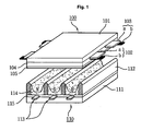
- FIG. 1 is a perspective view illustrating the construction of a general plasma display panel.
- the plasma display panel comprises a front substrate 100 and a rear substrate 110.
- a plurality of sustain electrode pairs in which scan electrodes 102 and sustain electrodes 103 are formed in pairs is arranged on a front glass 101 serving as a display surface on which images are displayed.
- a plurality of address electrodes 113 crossing the plurality of sustain electrode pairs is arranged on a rear glass 111 serving as a rear surface.
- the front substrate 100 and the rear substrate 110 are parallel to each other with a predetermined distance therebetween.
- the front substrate 100 comprises the pairs of scan electrodes 102 and sustain electrodes 103, which mutually discharge one another and maintain the emission of a cell within one discharge cell.
- each of the scan electrode 102 and the sustain electrode 103 has a transparent electrode "a” formed of a transparent ITO material and a bus electrode "b" formed of a metal material.
- the scan electrodes 102 and the sustain electrodes 103 are covered with one or more dielectric layers 104 for limiting a discharge current and providing insulation among the electrode pairs.
- a protection layer 105 having Magnesium Oxide (MgO) deposited thereon is formed on the dielectric layers 104 so as to facilitate discharge conditions.
- MgO Magnesium Oxide
- barrier ribs 112 of stripe form for forming a plurality of discharge spaces, i.e., discharge cells are arranged parallel to one another. Furthermore, a plurality of address electrodes 113, which generate vacuum ultraviolet rays by performing an address discharge, are disposed parallel to the barrier ribs 112. R, G and B phosphor layers 114 that radiate a visible ray for displaying images during an address discharge are coated on a top surface of the rear substrate 110. A dielectric layer 115 for protecting the address electrodes 113 is formed between the address electrodes 113 and the phosphor layers 114.
- FIG. 2 shows the structure of a plasma display apparatus adopting the plasma display panel of FIG. 1 in the related art.
- the related art plasma display apparatus comprises a casing 210 having a front cabinet 211 and a back cover 212 that form an external form, a plasma display panel 220 disposed within the casing 210, for implementing images by exciting phosphors with vacuum ultraviolet rays generated by a gas discharge, a plurality of driving circuit substrate 230 for driving and controlling the plasma display panel 220, a frame 240, which is connected to the plurality of driving circuit substrate 230 and has a heat dissipation function of dissipating heat generated when the plasma display apparatus is driven, a filter 250 formed at the front of the plasma display panel 220, a finger spring gasket 260 and a filter supporter 270 that support the filter 250 and electrically connect the filter 250 to the metal back cover 212, and a module supporter 280 that supports the plasma display panel 220 comprising the plurality of driving circuit substrate 230.
- Heat and noise are also inevitably generated from various elements attached on the plurality of driving circuit substrate 230 for forming a potential within the discharge cells for the purpose of a discharge of the plasma display panel 220.
- heat and noise generated from the discharge cells within the plasma display panel 220 and various elements attached on the plurality of driving circuit substrate 230 are major factors that degrade the quality of the plasma display apparatus.
- the plasma display panel 220 is completed through lost of manufacturing processes. Therefore, if any one process is performed in order to reduce noise, it has an affect on lots of subsequent processes. This requires a lot of manpower and expenses. This is a big loss from an economic point of view.
- an object of an embodiment of the present invention is to solve at least the problems and disadvantages of the background art.
- a plasma display apparatus comprises a plasma display panel in which upper and lower substrates are combined, a vibration damping sheet formed on a rear surface of the plasma display panel, and a plurality of driving circuit substrates formed on a rear surface of the vibration damping sheet, for driving the plasma display panel.
- a plasma display apparatus comprises a plasma display panel in which upper and lower substrates are combined, a heatproof sheet formed on a rear surface of the plasma display panel, a vibration damping sheet formed on a rear surface of the heatproof sheet, and a plurality of driving circuit substrates formed on a rear surface of the vibration damping sheet, for driving the plasma display panel.
- a plasma display apparatus comprises a plasma display panel in which upper and lower substrates are combined, a vibration damping sheet formed on a rear surface of the plasma display panel, a heatproof sheet formed on a rear surface of the vibration damping sheet, and a plurality of driving circuit substrates formed on a rear surface of the heatproof sheet, for driving the plasma display panel.
- the present invention is advantageous in that it can guarantee a high level of noise reduction and can save the manufacturing cost of a plasma display apparatus.
- FIG. 1 is a perspective view illustrating the structure of a general plasma display panel
- FIG. 2 shows the structure of a plasma display apparatus adopting the plasma display panel of FIG. 1 in the related art
- FIG. 3 is a dismantled perspective view illustrating the structure of a plasma display apparatus according to a first embodiment of the present invention
- FIG. 4 is a dismantled perspective view illustrating the structure of a plasma display apparatus according to a second embodiment of the present invention.
- FIG. 5 is a dismantled perspective view illustrating the structure of a plasma display apparatus according to a third embodiment of the present invention.
- FIG. 6 is a dismantled perspective view illustrating the structure of a plasma display apparatus according to a fourth embodiment of the present invention.
- FIG. 7 is a dismantled perspective view illustrating the structure of a plasma display apparatus according to a fifth embodiment of the present invention.
- FIG. 8 is a dismantled perspective view illustrating the structure of a plasma display apparatus according to a sixth embodiment of the present invention.
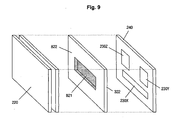
- FIG. 9 is a dismantled perspective view illustrating the structure of a plasma display apparatus according to a seventh embodiment of the present invention.
- a plasma display apparatus comprises a plasma display panel in which upper and lower substrates are combined, a vibration damping sheet formed on a rear surface of the plasma display panel, and a plurality of driving circuit substrates formed on a rear surface of the vibration damping sheet, for driving the plasma display panel.
- the plasma display apparatus further comprises a frame formed on the rear surface of the vibration damping sheet, for fixing the plurality of driving circuit substrates.
- the vibration damping sheet comprises at least one of a polymer-based material and a fiber type inorganic material.
- the vibration damping sheet comprises a thermal conductive material.
- the thermal conductive material is carbon (C).
- a plasma display apparatus comprises a plasma display panel in which upper and lower substrates are combined, a heatproof sheet formed on a rear surface of the plasma display panel, a vibration damping sheet formed on a rear surface of the heatproof sheet, and a plurality of driving circuit substrates formed on a rear surface of the vibration damping sheet, for driving the plasma display panel.
- the plasma display apparatus further comprises a frame formed on the rear surface of the vibration damping sheet, for fixing the plurality of driving circuit substrates.
- the vibration damping sheet is attached opposite to at least one or more of the plurality of driving circuit substrates.
- the vibration damping sheet comprises at least one of a polymer-based material and a fiber type inorganic material.
- the vibration damping sheet comprises a thermal conductive material, and the thermal conductive material is carbon (C).
- a groove is formed in a rear surface of the heatproof sheet, and the vibration damping sheet is formed in the groove.
- the vibration damping sheet comprises at least one of a polymer-based material and a fiber type inorganic material.
- the vibration damping sheet comprises a thermal conductive material, and the thermal conductive material is carbon (C).
- a plasma display apparatus comprises a plasma display panel in which upper and lower substrates are combined, a vibration damping sheet formed on a rear surface of the plasma display panel, a heatproof sheet formed on a rear surface of the vibration damping sheet, and a plurality of driving circuit substrates formed on a rear surface of the heatproof sheet, for driving the plasma display panel.
- the plasma display apparatus further comprises a frame formed on the rear surface of the heatproof sheet, for fixing the plurality of driving circuit substrates.
- the vibration damping sheet is attached opposite to at least one or more of the plurality of driving circuit substrates.
- the vibration damping sheet comprises at least one of a polymer-based material and a fiber type inorganic material.
- the vibration damping sheet comprises a thermal conductive material, and the thermal conductive material is carbon (C).
- a groove is formed in a front surface of the heatproof sheet, and the vibration damping sheet is formed in the groove.
- the vibration damping sheet comprises at least one of a polymer-based material and a fiber type inorganic material, the vibration damping sheet comprises a thermal conductive material, and the thermal conductive material is carbon (C).
- FIG. 3 is a dismantled perspective view illustrating the structure of a plasma display apparatus according to a first embodiment of the present invention.
- the plasma display apparatus comprises a plasma display panel 220 in which an upper and lower substrates are combined and on which images are displayed by a gas discharge, a vibration damping sheet 321 formed on a rear surface of the plasma display panel 220, for precluding noise occurring from discharge cells within the plasma display panel 220 and driving circuit elements when the plasma display panel 220 is driving for a discharge, a frame 240 formed on a rear surface of the vibration damping sheet 321, for fixing a plurality of driving circuit substrates that drive the plasma display panel 220, and a plurality of driving circuit substrates 230X, 230Y and 230Z fixed to a rear surface of the frame 240, for driving the plasma display panel 220.
- the plasma display apparatus constructed above inevitably generates heat and noise when a discharge is generated in the discharge cells within the plasma display panel 220. Heat and noise are also inevitably generated even in various elements attached on the plurality of driving circuit substrates 230X, 230Y and 230Z for forming a potential within the discharge cells for the purpose of a discharge of the plasma display panel 220.
- heat and noise radiated from the discharge cells within the plasma display panel 220 and various elements attached on the plurality of driving circuit substrates 230X, 230Y and 230Z are major factors that degrade the quality of the plasma display apparatus.
- the vibration damping sheet 321 is disposed between the plasma display panel 220 and the frame 240 in which the plurality of driving circuit substrates 230X, 230Y and 230Z are mounted, as shown in FIG. 3.
- the vibration damping sheet 321 is attached so that it is brought in contact with the plasma display panel 220 and the frame 240 in which the plurality of driving circuit substrates 230X, 230Y and 230Z are mounted as described above, the transfer of vibration occurring when the plasma display panel 220 is discharged and vibration occurring when a voltage is applied to the driving elements in order to drive the plasma display panel 220 can be prevented. It is thus possible to preclude noise from radiating to the outside.
- the vibration damping sheet 321 can preferably comprise at least one of a polymer-based material and a fiber type inorganic material. More preferably, if the vibration damping sheet 321 comprises both the polymer-based material and the fiber type inorganic material, the transfer of vibration, which is a main cause of noise, can be precluded using frication between polymer and fiber. Therefore, noise can be attenuated within the vibration damping sheet 321 and then disappear.
- the vibration damping sheet 321 can preferably comprise a thermal conductive material. More preferably, the thermal conductive material can be formed of carbon (C). Therefore, the thermal conductive material performs a heat dissipation function along with a heatproof sheet 322, so that the heat dissipation function of the plasma display apparatus can be doubled.
- C carbon
- FIG. 4 is a dismantled perspective view illustrating the structure of a plasma display apparatus according to a second embodiment of the present invention.
- the plasma display apparatus comprises a plasma display panel 220 in which an upper and lower substrates are combined and on which images are displayed by a gas discharge, a heatproof sheet 322 formed on a rear surface of the plasma display panel 220, for precluding heat generating from discharge cells within the plasma display panel 220 and driving circuit elements when the plasma display panel 220 is driving for a discharge, a vibration damping sheet 321 formed on a rear surface of the plasma display panel 220, for precluding noise occurring from discharge cells within the plasma display panel 220 and driving circuit elements when the plasma display panel 220 is driving for a discharge, a frame 240 formed on a rear surface of the vibration damping sheet 321, for fixing a plurality of driving circuit substrates 230X, 230Y and 230Z that drive the plasma display panel 220, and the plurality of driving circuit substrates 230X, 230Y and 230Z fixed to a rear surface of the frame 240, for driving the plasma display panel 220.
- the plasma display apparatus constructed above inevitably generates heat and noise when a discharge is generated in the discharge cells within the plasma display panel 220. Heat and noise are also inevitably generated even in various elements attached on the plurality of driving circuit substrates 230X, 230Y and 230Z for forming a potential within the discharge cells for the purpose of a discharge of the plasma display panel 220.
- heat and noise radiated from the discharge cells within the plasma display panel 220 and various elements attached on the plurality of driving circuit substrates 230X, 230Y and 230Z are major factors that degrade the quality of the plasma display apparatus.
- the vibration damping sheet 321 is disposed between the heatproof sheet 322 and the frame 240 in which the plurality of driving circuit substrates 230X, 230Y and 230Z are mounted, as shown in FIG. 4.
- the vibration damping sheet 321 is attached so that it is brought in contact with the heatproof sheet 322 and the frame 240 in which the plurality of driving circuit substrates 230X, 230Y and 230Z are mounted as described above, the transfer of vibration occurring when the plasma display panel 220 is discharged and vibration occurring when a voltage is applied to the driving elements in order to drive the plasma display panel 220 can be prevented. It is thus possible to preclude noise from radiating to the outside.
- the vibration damping sheet 321 can preferably comprise at least one of a polymer-based material and a fiber type inorganic material. More preferably, if the vibration damping sheet 321 comprises both the polymer-based material and the fiber type inorganic material, the transfer of vibration, which is a main cause of noise, can be precluded using frication between polymer and fiber. Therefore, noise can be attenuated within the vibration damping sheet 321 and then disappear.
- the vibration damping sheet 321 can preferably comprise a thermal conductive material. More preferably, the thermal conductive material can be formed of carbon (C). Therefore, the thermal conductive material performs a heat dissipation function along with a heatproof sheet 322, so that the heat dissipation function of the plasma display apparatus can be doubled.
- C carbon
- FIG. 5 is a dismantled perspective view illustrating the structure of a plasma display apparatus according to a third embodiment of the present invention.
- the plasma display apparatus comprises a plasma display panel 220 in which an upper and lower substrates are combined and on which images are displayed by a gas discharge, a vibration damping sheet 321 formed on a rear surface of the plasma display panel 220, for precluding noise occurring from discharge cells within the plasma display panel 220 and driving circuit elements when the plasma display panel 220 is driving for a discharge, a heatproof sheet 322 formed on a rear surface of the vibration damping sheet 321, for precluding heat generating from discharge cells within the plasma display panel 220 and driving circuit elements when the plasma display panel 220 is driving for a discharge, a frame 240 formed on a rear surface of the heatproof sheet 322, for fixing a plurality of driving circuit substrates 230X, 230Y and 230Z that drive the plasma display panel 220, and the plurality of driving circuit substrates 230X, 230Y and 230Z fixed to a rear surface of the frame 240, for driving the plasma display panel 220.
- the plasma display apparatus constructed above inevitably generates heat and noise when a discharge is generated in the discharge cells within the plasma display panel 220. Heat and noise are also inevitably generated even in various elements attached on the plurality of driving circuit substrates 230X, 230Y and 230Z for forming a potential within the discharge cells for the purpose of a discharge of the plasma display panel 220.
- heat and noise radiated from the discharge cells within the plasma display panel 220 and various elements attached on the plurality of driving circuit substrates 230X, 230Y and 230Z are major factors that degrade the quality of the plasma display apparatus.
- the vibration damping sheet 321 is disposed between the plasma display panel 220 and the heatproof sheet 322, as shown in FIG. 5.
- the vibration damping sheet 321 is attached so that it is brought in contact with the plasma display panel 220 and the heatproof sheet 322 as described above, the transfer of vibration occurring when the plasma display panel 220 is discharged and vibration occurring when a voltage is applied to the driving elements in order to drive the plasma display panel 220 can be prevented. It is thus possible to preclude noise from radiating to the outside.
- the vibration damping sheet 321 can preferably comprise at least one of a polymer-based material and a fiber type inorganic material. More preferably, if the vibration damping sheet 321 comprises both the polymer-based material and the fiber type inorganic material, the transfer of vibration, which is a main cause of noise, can be precluded using frication between polymer and fiber. Therefore, noise can be attenuated within the vibration damping sheet 321 and then disappear.
- the vibration damping sheet 321 can preferably comprise a thermal conductive material. More preferably, the thermal conductive material can be formed of carbon (C). Therefore, the thermal conductive material performs a heat dissipation function along with a heatproof sheet 322, so that the heat dissipation function of the plasma display apparatus can be doubled.
- C carbon
- FIG. 6 is a dismantled perspective view illustrating the structure of a plasma display apparatus according to a fourth embodiment of the present invention.
- the plasma display apparatus comprises a plasma display panel 220 in which an upper and lower substrates are combined and on which images are displayed by a gas discharge, a heatproof sheet 322 formed on a rear surface of the plasma display panel 220, for precluding heat generating from discharge cells within the plasma display panel 220 and driving circuit elements when the plasma display panel 220 is driving for a discharge, a vibration damping sheet 621X, 621Y and 621Z formed on a rear surface of the heatproof sheet 322 in such a way to be opposite to at least one or more of a plurality of driving circuit substrates 230X, 230Y and 230Z, for precluding noise generating from the discharge cells within the plasma display panel 220 and the plurality of driving circuit elements when the plasma display panel 220 is driving for a discharge, a frame 240 formed on a rear surface of the heatproof sheet 322, for fixing a plurality of driving circuit substrates 230X, 230Y and 230Z that
- the plasma display apparatus constructed above inevitably generates heat and noise when a discharge is generated in the discharge cells within the plasma display panel 220. Heat and noise are also inevitably generated even in various elements attached on the plurality of driving circuit substrates 230X, 230Y and 230Z for forming a potential within the discharge cells for the purpose of a discharge of the plasma display panel 220.
- heat and noise radiated from the discharge cells within the plasma display panel 220 and various elements attached on the plurality of driving circuit substrates 230X, 230Y and 230Z are major factors that degrade the quality of the plasma display apparatus.
- the vibration damping sheet 621X, 621Y and 621Z are formed to be opposite to at least one or more of the plurality of driving circuit substrates 230X, 230Y and 230Z between the heatproof sheet 322 and the frame 240 in which the plurality of driving circuit substrates 230X, 230Y and 230Z are mounted, as shown in FIG. 6.
- vibration damping sheet 621X, 621Y and 621Z are attached so that they are brought in contact with the plasma display panel 220 and the heatproof sheet 322 as described above, the transfer of vibration occurring when the plasma display panel 220 is discharged and vibration occurring when a voltage is applied to the driving elements in order to drive the plasma display panel 220 can be prevented. It is thus possible to preclude noise from radiating to the outside.
- the vibration damping sheet 621X, 621Y and 621Z can preferably comprise at least one of a polymer-based material and a fiber type inorganic material. More preferably, if the vibration damping sheet 621X, 621Y and 621Z comprises both the polymer-based material and the fiber type inorganic material, the transfer of vibration, which is a main cause of noise, can be precluded through frication between polymer and fiber. Therefore, noise can be attenuated within the vibration damping sheet 621X, 621Y and 621Z and then disappear.
- the vibration damping sheet 621X, 621Y and 621Z can preferably comprise a thermal conductive material. More preferably, the thermal conductive material can be formed of carbon (C). Therefore, the thermal conductive material performs a heat dissipation function along with a heatproof sheet 322, so that the heat dissipation function of the plasma display apparatus can be doubled.
- the thermal conductive material can be formed of carbon (C). Therefore, the thermal conductive material performs a heat dissipation function along with a heatproof sheet 322, so that the heat dissipation function of the plasma display apparatus can be doubled.
- FIG. 7 is a dismantled perspective view illustrating the structure of a plasma display apparatus according to a fifth embodiment of the present invention.
- the plasma display apparatus comprises a plasma display panel 220 in which an upper and lower substrates are combined and on which images are displayed by a gas discharge, a vibration damping sheet 621X, 621Y and 621Z formed on a rear surface of the plasma display panel 220 in such a way to be opposite to at least one or more of a plurality of driving circuit substrates 230X, 230Y and 230Z, for precluding noise generating from discharge cells within the plasma display panel 220 and driving circuit elements when the plasma display panel 220 is driving for a discharge, a heatproof sheet 322 formed on a rear surface of the vibration damping sheet 621X, 621Y and 621Z, for precluding heat generating from the discharge cells within the plasma display panel 220 and the plurality of driving circuit elements when the plasma display panel 220 is driving for a discharge, a frame 240 formed on a rear surface of the heatproof sheet 322, for fixing a plurality of driving circuit substrates 230
- the plasma display apparatus constructed above inevitably generates heat and noise when a discharge is generated in the discharge cells within the plasma display panel 220. Heat and noise are also inevitably generated even in various elements attached on the plurality of driving circuit substrates 230X, 230Y and 230Z for forming a potential within the discharge cells for the purpose of a discharge of the plasma display panel 220.
- heat and noise radiated from the discharge cells within the plasma display panel 220 and various elements attached on the plurality of driving circuit substrates 230X, 230Y and 230Z are major factors that degrade the quality of the plasma display apparatus.
- the vibration damping sheet 621X, 621Y and 621Z are formed between the plasma display panel 220 and the heatproof sheet 322, as shown in FIG. 7.
- vibration damping sheet 621X, 621Y and 621Z are attached so that they are brought in contact with the plasma display panel 220 and the heatproof sheet 322 as described above, the transfer of vibration occurring when the plasma display panel 220 is discharged and vibration occurring when a voltage is applied to the driving elements in order to drive the plasma display panel 220 can be prevented. It is thus possible to preclude noise from radiating to the outside.
- the vibration damping sheet 621X, 621Y and 621Z can preferably comprise at least one of a polymer-based material and a fiber type inorganic material. More preferably, if the vibration damping sheet 321 comprises both the polymer-based material and the fiber type inorganic material, the transfer of vibration, which is a main cause of noise, can be precluded using frication between polymer and fiber. Therefore, noise can be attenuated within the vibration damping sheet 621X, 621Y and 621Z and then disappear.
- the vibration damping sheet 621X, 621Y and 621Z can preferably comprise a thermal conductive material. More preferably, the thermal conductive material can be formed of carbon (C). Therefore, the thermal conductive material performs a heat dissipation function along with a heatproof sheet 322, so that the heat dissipation function of the plasma display apparatus can be doubled.
- the thermal conductive material can be formed of carbon (C). Therefore, the thermal conductive material performs a heat dissipation function along with a heatproof sheet 322, so that the heat dissipation function of the plasma display apparatus can be doubled.
- FIG. 8 is a dismantled perspective view illustrating the structure of a plasma display apparatus according to a sixth embodiment of the present invention.
- the plasma display apparatus comprises a plasma display panel 220 in which an upper and lower substrates are combined and on which images are displayed by a gas discharge, a heatproof sheet 822 formed on a rear surface of the plasma display panel 220, for precluding heat generating from discharge cells within the plasma display panel 220 and driving circuit elements when the plasma display panel 220 is driving for a discharge, a vibration damping sheet 821 formed within a groove having a predetermined width at the rear side of the plasma display panel 220, for precluding noise occurring from discharge cells within the plasma display panel 220 and driving circuit elements when the plasma display panel 220 is driving for a discharge, a frame 240 formed on a rear surface of the vibration damping sheet 821, for fixing a plurality of driving circuit substrates 230X, 230Y and 230Z that drive the plasma display panel 220, and the plurality of driving circuit substrates 230X, 230Y and 230Z fixed to a rear surface of the frame 240
- the plasma display apparatus constructed above inevitably generates heat and noise when a discharge is generated in the discharge cells within the plasma display panel 220. Heat and noise are also inevitably generated even in various elements attached on the plurality of driving circuit substrates 230X, 230Y and 230Z for forming a potential within the discharge cells for the purpose of a discharge of the plasma display panel 220.
- heat and noise radiated from the discharge cells within the plasma display panel 220 and various elements attached on the plurality of driving circuit substrates 230X, 230Y and 230Z are major factors that degrade the quality of the plasma display apparatus.
- the vibration damping sheet 821 is disposed between the heatproof sheet 822 and the frame 240 in which the plurality of driving circuit substrates 230X, 230Y and 230Z are mounted, as shown in FIG. 8.
- the vibration damping sheet 821 is brought in contact with the heatproof sheet 822 and the frame 240 in which the plurality of driving circuit substrates 230X, 230Y and 230Z are mounted as described above, the transfer of vibration occurring when the plasma display panel 220 is discharged and vibration occurring when a voltage is applied to the driving elements in order to drive the plasma display panel 220 can be prevented. It is thus possible to preclude noise from radiating to the outside.
- the vibration damping sheet 821 can preferably comprise at least one of a polymer-based material and a fiber type inorganic material. More preferably, if the vibration damping sheet 821 comprises both the polymer-based material and the fiber type inorganic material, the transfer of vibration, which is a main cause of noise, can be precluded using frication between polymer and fiber. Therefore, noise can be attenuated within the vibration damping sheet 821 and then disappear.
- the vibration damping sheet 821 can preferably comprise a thermal conductive material. More preferably, the thermal conductive material can be formed of carbon (C). Therefore, the thermal conductive material performs a heat dissipation function along with a heatproof sheet 822, so that the heat dissipation function of the plasma display apparatus can be doubled.
- C carbon
- FIG. 9 is a dismantled perspective view illustrating the structure of a plasma display apparatus according to a seventh embodiment of the present invention.
- the plasma display apparatus comprises a plasma display panel 220 in which an upper and lower substrates are combined and on which images are displayed by a gas discharge, a vibration damping sheet 821, which is adhered to a rear surface of the plasma display panel 220 and is formed within a groove having a predetermined width at the front side of a heatproof sheet 822, for precluding noise occurring from discharge cells within the plasma display panel 220 and driving circuit elements when the plasma display panel 220 is driving for a discharge, a heatproof sheet 822 formed on a rear surface of the vibration damping sheet 821, for precluding heat generating from the discharge cells within the plasma display panel 220 and the plurality of driving circuit elements when the plasma display panel 220 is driving for a discharge, a frame 240 formed on a rear surface of the heatproof sheet, for fixing a plurality of driving circuit substrates 230X, 230Y and 230Z that drive the plasma display panel 220, and the plurality of driving circuit substrate
- the plasma display apparatus constructed above inevitably generates heat and noise when a discharge is generated in the discharge cells within the plasma display panel 220. Heat and noise are also inevitably generated even in various elements attached on the plurality of driving circuit substrates 230X, 230Y and 230Z for forming a potential within the discharge cells for the purpose of a discharge of the plasma display panel 220.
- heat and noise radiated from the discharge cells within the plasma display panel 220 and various elements attached on the plurality of driving circuit substrates 230X, 230Y and 230Z are major factors that degrade the quality of the plasma display apparatus.
- the vibration damping sheet 821 is disposed between the plasma display panel 220 and the heatproof sheet 822, as shown in FIG. 9.
- the vibration damping sheet 821 is brought in contact with the plasma display panel 220 and the heatproof sheet 822 as described above, the transfer of vibration occurring when the plasma display panel 220 is discharged and vibration occurring when a voltage is applied to the driving elements in order to drive the plasma display panel 220 can be prevented. It is thus possible to preclude noise from radiating to the outside.
- the vibration damping sheet 821 can preferably comprise at least one of a polymer-based material and a fiber type inorganic material. More preferably, if the vibration damping sheet 821 comprises both the polymer-based material and the fiber type inorganic material, the transfer of vibration, which is a main cause of noise, can be precluded using frication between polymer and fiber. Therefore, noise can be attenuated within the vibration damping sheet 821 and then disappear.
- the vibration damping sheet 821 can preferably comprise a thermal conductive material. More preferably, the thermal conductive material can be formed of carbon (C). Therefore, the thermal conductive material performs a heat dissipation function along with a heatproof sheet 822, so that the heat dissipation function of the plasma display apparatus can be doubled.
- C carbon
- the present invention is advantageous in that it can guarantee a high level of noise reduction and can save the manufacturing cost of a plasma display apparatus.
Landscapes
- Engineering & Computer Science (AREA)
- Microelectronics & Electronic Packaging (AREA)
- Physics & Mathematics (AREA)
- Plasma & Fusion (AREA)
- Devices For Indicating Variable Information By Combining Individual Elements (AREA)
- Gas-Filled Discharge Tubes (AREA)
Abstract
This document invention relates to a display apparatus, and more particularly, to a plasma display apparatus. The plasma display apparatus according to an embodiment of the present invention comprises a plasma display panel in which upper and lower substrates are combined, a vibration damping sheet formed on a rear surface of the plasma display panel, and a plurality of driving circuit substrates formed on a rear surface of the vibration damping sheet, for driving the plasma display panel. According to an embodiment of the present invention, noise occurring in a discharge of a plasma display panel and driving circuit elements is precluded. Therefore, a high level of noise reduction can guaranted and the manufacturing cost of a plasma display apparatus can be saved.
Description
- This document relates to a display apparatus, and more particularly, to a plasma display apparatus.
- In general, a plasma display apparatus of a display apparatus comprises a plasma display panel and a driver for driving the plasma display panel.
- In general, in a plasma display panel, a barrier rib formed between a front substrate and a rear substrate forms one unit cell. Each cell is filled with an inert gas containing a primary discharge gas, such as neon (Ne), helium (He) or a mixed gas of Ne+He, and a small amount of xenon (Xe). If the inert gas is discharged with a high frequency voltage, vacuum ultraviolet rays are generated. Phosphors formed between the barrier ribs are excited to implement images. The plasma display panel can be made thin, and has thus been in the spotlight as the next-generation display devices.
- FIG. 1 is a perspective view illustrating the construction of a general plasma display panel. As shown in FIG. 1, the plasma display panel comprises a
front substrate 100 and arear substrate 110. In thefront substrate 100, a plurality of sustain electrode pairs in whichscan electrodes 102 and sustainelectrodes 103 are formed in pairs is arranged on afront glass 101 serving as a display surface on which images are displayed. In therear substrate 110, a plurality ofaddress electrodes 113 crossing the plurality of sustain electrode pairs is arranged on arear glass 111 serving as a rear surface. At this time, thefront substrate 100 and therear substrate 110 are parallel to each other with a predetermined distance therebetween. - The
front substrate 100 comprises the pairs ofscan electrodes 102 and sustainelectrodes 103, which mutually discharge one another and maintain the emission of a cell within one discharge cell. In other words, each of thescan electrode 102 and thesustain electrode 103 has a transparent electrode "a" formed of a transparent ITO material and a bus electrode "b" formed of a metal material. Thescan electrodes 102 and thesustain electrodes 103 are covered with one or moredielectric layers 104 for limiting a discharge current and providing insulation among the electrode pairs. A protection layer 105 having Magnesium Oxide (MgO) deposited thereon is formed on thedielectric layers 104 so as to facilitate discharge conditions. - In the
rear substrate 110,barrier ribs 112 of stripe form (or well form), for forming a plurality of discharge spaces, i.e., discharge cells are arranged parallel to one another. Furthermore, a plurality ofaddress electrodes 113, which generate vacuum ultraviolet rays by performing an address discharge, are disposed parallel to thebarrier ribs 112. R, G andB phosphor layers 114 that radiate a visible ray for displaying images during an address discharge are coated on a top surface of therear substrate 110. Adielectric layer 115 for protecting theaddress electrodes 113 is formed between theaddress electrodes 113 and thephosphor layers 114. - FIG. 2 shows the structure of a plasma display apparatus adopting the plasma display panel of FIG. 1 in the related art.
- As shown in FIG. 2, the related art plasma display apparatus comprises a
casing 210 having afront cabinet 211 and aback cover 212 that form an external form, aplasma display panel 220 disposed within thecasing 210, for implementing images by exciting phosphors with vacuum ultraviolet rays generated by a gas discharge, a plurality ofdriving circuit substrate 230 for driving and controlling theplasma display panel 220, aframe 240, which is connected to the plurality ofdriving circuit substrate 230 and has a heat dissipation function of dissipating heat generated when the plasma display apparatus is driven, afilter 250 formed at the front of theplasma display panel 220, afinger spring gasket 260 and afilter supporter 270 that support thefilter 250 and electrically connect thefilter 250 to themetal back cover 212, and amodule supporter 280 that supports theplasma display panel 220 comprising the plurality ofdriving circuit substrate 230. - In the related art plasma display apparatus constructed above, when a discharge is generated in discharge cells within the
plasma display panel 220, heat and noise are essentially generated. - Heat and noise are also inevitably generated from various elements attached on the plurality of
driving circuit substrate 230 for forming a potential within the discharge cells for the purpose of a discharge of theplasma display panel 220. - As described above, heat and noise generated from the discharge cells within the
plasma display panel 220 and various elements attached on the plurality ofdriving circuit substrate 230 are major factors that degrade the quality of the plasma display apparatus. - More particularly, recently, a noise problem of the plasma display apparatus surfaces as an important issue. It is very difficult to fundamentally solve the noise problem.
- The reason will now be described with reference to various elements attached on the
plasma display panel 220 and the plurality ofdriving circuit substrate 230. - The
plasma display panel 220 is completed through lost of manufacturing processes. Therefore, if any one process is performed in order to reduce noise, it has an affect on lots of subsequent processes. This requires a lot of manpower and expenses. This is a big loss from an economic point of view. - Furthermore, to solve the problem on case-by-case basis by analyzing the cause of noise into lots of various elements attached on the plurality of
driving circuit substrate 230 also requires a great amount of manpower and cost. This results in a significant loss in terms of economy. - Accordingly, an object of an embodiment of the present invention is to solve at least the problems and disadvantages of the background art.
- It is an object of an embodiment of the present invention to preclude noise occurring in a discharge of a plasma display panel and driving circuit elements with low cost.
- It is another object of an embodiment of the present invention to improve a heatproof effect by adding a thermal conductive material to a vibration damping sheet.
- A plasma display apparatus according to an embodiment of the present invention comprises a plasma display panel in which upper and lower substrates are combined, a vibration damping sheet formed on a rear surface of the plasma display panel, and a plurality of driving circuit substrates formed on a rear surface of the vibration damping sheet, for driving the plasma display panel.
- A plasma display apparatus according to another embodiment of the present invention comprises a plasma display panel in which upper and lower substrates are combined, a heatproof sheet formed on a rear surface of the plasma display panel, a vibration damping sheet formed on a rear surface of the heatproof sheet, and a plurality of driving circuit substrates formed on a rear surface of the vibration damping sheet, for driving the plasma display panel.
- A plasma display apparatus according to still another embodiment of the present invention comprises a plasma display panel in which upper and lower substrates are combined, a vibration damping sheet formed on a rear surface of the plasma display panel, a heatproof sheet formed on a rear surface of the vibration damping sheet, and a plurality of driving circuit substrates formed on a rear surface of the heatproof sheet, for driving the plasma display panel.
- According to the present invention, noise occurring in a discharge of a plasma display panel and driving circuit elements is precluded. Therefore, the present invention is advantageous in that it can guarantee a high level of noise reduction and can save the manufacturing cost of a plasma display apparatus.
- The embodiment of the invention will be described in detail with reference to the following drawings in which like numerals refer to like elements.
- FIG. 1 is a perspective view illustrating the structure of a general plasma display panel;
- FIG. 2 shows the structure of a plasma display apparatus adopting the plasma display panel of FIG. 1 in the related art;
- FIG. 3 is a dismantled perspective view illustrating the structure of a plasma display apparatus according to a first embodiment of the present invention;
- FIG. 4 is a dismantled perspective view illustrating the structure of a plasma display apparatus according to a second embodiment of the present invention;
- FIG. 5 is a dismantled perspective view illustrating the structure of a plasma display apparatus according to a third embodiment of the present invention;
- FIG. 6 is a dismantled perspective view illustrating the structure of a plasma display apparatus according to a fourth embodiment of the present invention;
- FIG. 7 is a dismantled perspective view illustrating the structure of a plasma display apparatus according to a fifth embodiment of the present invention;
- FIG. 8 is a dismantled perspective view illustrating the structure of a plasma display apparatus according to a sixth embodiment of the present invention; and
- FIG. 9 is a dismantled perspective view illustrating the structure of a plasma display apparatus according to a seventh embodiment of the present invention.
- Embodiments of the present invention will be described in a more detailed manner with reference to the drawings.
- A plasma display apparatus according to an embodiment of the present invention comprises a plasma display panel in which upper and lower substrates are combined, a vibration damping sheet formed on a rear surface of the plasma display panel, and a plurality of driving circuit substrates formed on a rear surface of the vibration damping sheet, for driving the plasma display panel.
- The plasma display apparatus further comprises a frame formed on the rear surface of the vibration damping sheet, for fixing the plurality of driving circuit substrates.
- The vibration damping sheet comprises at least one of a polymer-based material and a fiber type inorganic material.
- The vibration damping sheet comprises a thermal conductive material.
- The thermal conductive material is carbon (C).
- A plasma display apparatus according to another embodiment of the present invention comprises a plasma display panel in which upper and lower substrates are combined, a heatproof sheet formed on a rear surface of the plasma display panel, a vibration damping sheet formed on a rear surface of the heatproof sheet, and a plurality of driving circuit substrates formed on a rear surface of the vibration damping sheet, for driving the plasma display panel.
- The plasma display apparatus further comprises a frame formed on the rear surface of the vibration damping sheet, for fixing the plurality of driving circuit substrates.
- The vibration damping sheet is attached opposite to at least one or more of the plurality of driving circuit substrates.
- The vibration damping sheet comprises at least one of a polymer-based material and a fiber type inorganic material.
- The vibration damping sheet comprises a thermal conductive material, and the thermal conductive material is carbon (C).
- A groove is formed in a rear surface of the heatproof sheet, and the vibration damping sheet is formed in the groove.
- The vibration damping sheet comprises at least one of a polymer-based material and a fiber type inorganic material.
- The vibration damping sheet comprises a thermal conductive material, and the thermal conductive material is carbon (C).
- A plasma display apparatus according to still another embodiment of the present invention comprises a plasma display panel in which upper and lower substrates are combined, a vibration damping sheet formed on a rear surface of the plasma display panel, a heatproof sheet formed on a rear surface of the vibration damping sheet, and a plurality of driving circuit substrates formed on a rear surface of the heatproof sheet, for driving the plasma display panel.
- The plasma display apparatus further comprises a frame formed on the rear surface of the heatproof sheet, for fixing the plurality of driving circuit substrates.
- The vibration damping sheet is attached opposite to at least one or more of the plurality of driving circuit substrates.
- The vibration damping sheet comprises at least one of a polymer-based material and a fiber type inorganic material.
- The vibration damping sheet comprises a thermal conductive material, and the thermal conductive material is carbon (C).
- A groove is formed in a front surface of the heatproof sheet, and the vibration damping sheet is formed in the groove.
- The vibration damping sheet comprises at least one of a polymer-based material and a fiber type inorganic material, the vibration damping sheet comprises a thermal conductive material, and the thermal conductive material is carbon (C).
- Detailed embodiments of the present invention will now be described in connection with reference to the accompanying drawings.
- FIG. 3 is a dismantled perspective view illustrating the structure of a plasma display apparatus according to a first embodiment of the present invention.
- As shown in FIG. 3, the plasma display apparatus according to a first embodiment of the present invention comprises a
plasma display panel 220 in which an upper and lower substrates are combined and on which images are displayed by a gas discharge, avibration damping sheet 321 formed on a rear surface of theplasma display panel 220, for precluding noise occurring from discharge cells within theplasma display panel 220 and driving circuit elements when theplasma display panel 220 is driving for a discharge, aframe 240 formed on a rear surface of thevibration damping sheet 321, for fixing a plurality of driving circuit substrates that drive theplasma display panel 220, and a plurality of drivingcircuit substrates frame 240, for driving theplasma display panel 220. - The plasma display apparatus constructed above inevitably generates heat and noise when a discharge is generated in the discharge cells within the
plasma display panel 220. Heat and noise are also inevitably generated even in various elements attached on the plurality of drivingcircuit substrates plasma display panel 220. - As described above, heat and noise radiated from the discharge cells within the
plasma display panel 220 and various elements attached on the plurality of drivingcircuit substrates - In the present invention, to prevent such noise from radiating outside the plasma display apparatus, the
vibration damping sheet 321 is disposed between theplasma display panel 220 and theframe 240 in which the plurality of drivingcircuit substrates - If the
vibration damping sheet 321 is attached so that it is brought in contact with theplasma display panel 220 and theframe 240 in which the plurality of drivingcircuit substrates plasma display panel 220 is discharged and vibration occurring when a voltage is applied to the driving elements in order to drive theplasma display panel 220 can be prevented. It is thus possible to preclude noise from radiating to the outside. - At this time, the
vibration damping sheet 321 can preferably comprise at least one of a polymer-based material and a fiber type inorganic material. More preferably, if thevibration damping sheet 321 comprises both the polymer-based material and the fiber type inorganic material, the transfer of vibration, which is a main cause of noise, can be precluded using frication between polymer and fiber. Therefore, noise can be attenuated within thevibration damping sheet 321 and then disappear. - Furthermore, the
vibration damping sheet 321 can preferably comprise a thermal conductive material. More preferably, the thermal conductive material can be formed of carbon (C). Therefore, the thermal conductive material performs a heat dissipation function along with aheatproof sheet 322, so that the heat dissipation function of the plasma display apparatus can be doubled. - FIG. 4 is a dismantled perspective view illustrating the structure of a plasma display apparatus according to a second embodiment of the present invention.
- As shown in FIG. 4, the plasma display apparatus according to a second embodiment of the present invention comprises a
plasma display panel 220 in which an upper and lower substrates are combined and on which images are displayed by a gas discharge, aheatproof sheet 322 formed on a rear surface of theplasma display panel 220, for precluding heat generating from discharge cells within theplasma display panel 220 and driving circuit elements when theplasma display panel 220 is driving for a discharge, avibration damping sheet 321 formed on a rear surface of theplasma display panel 220, for precluding noise occurring from discharge cells within theplasma display panel 220 and driving circuit elements when theplasma display panel 220 is driving for a discharge, aframe 240 formed on a rear surface of thevibration damping sheet 321, for fixing a plurality of drivingcircuit substrates plasma display panel 220, and the plurality of drivingcircuit substrates frame 240, for driving theplasma display panel 220. - The plasma display apparatus constructed above inevitably generates heat and noise when a discharge is generated in the discharge cells within the
plasma display panel 220. Heat and noise are also inevitably generated even in various elements attached on the plurality of drivingcircuit substrates plasma display panel 220. - As described above, heat and noise radiated from the discharge cells within the
plasma display panel 220 and various elements attached on the plurality of drivingcircuit substrates - In the present invention, to prevent such noise from radiating outside the plasma display apparatus, the
vibration damping sheet 321 is disposed between theheatproof sheet 322 and theframe 240 in which the plurality of drivingcircuit substrates - If the
vibration damping sheet 321 is attached so that it is brought in contact with theheatproof sheet 322 and theframe 240 in which the plurality of drivingcircuit substrates plasma display panel 220 is discharged and vibration occurring when a voltage is applied to the driving elements in order to drive theplasma display panel 220 can be prevented. It is thus possible to preclude noise from radiating to the outside. - At this time, the
vibration damping sheet 321 can preferably comprise at least one of a polymer-based material and a fiber type inorganic material. More preferably, if thevibration damping sheet 321 comprises both the polymer-based material and the fiber type inorganic material, the transfer of vibration, which is a main cause of noise, can be precluded using frication between polymer and fiber. Therefore, noise can be attenuated within thevibration damping sheet 321 and then disappear. - Furthermore, the
vibration damping sheet 321 can preferably comprise a thermal conductive material. More preferably, the thermal conductive material can be formed of carbon (C). Therefore, the thermal conductive material performs a heat dissipation function along with aheatproof sheet 322, so that the heat dissipation function of the plasma display apparatus can be doubled. - FIG. 5 is a dismantled perspective view illustrating the structure of a plasma display apparatus according to a third embodiment of the present invention.
- As shown in FIG. 5, the plasma display apparatus according to a third embodiment of the present invention comprises a
plasma display panel 220 in which an upper and lower substrates are combined and on which images are displayed by a gas discharge, avibration damping sheet 321 formed on a rear surface of theplasma display panel 220, for precluding noise occurring from discharge cells within theplasma display panel 220 and driving circuit elements when theplasma display panel 220 is driving for a discharge, aheatproof sheet 322 formed on a rear surface of thevibration damping sheet 321, for precluding heat generating from discharge cells within theplasma display panel 220 and driving circuit elements when theplasma display panel 220 is driving for a discharge, aframe 240 formed on a rear surface of theheatproof sheet 322, for fixing a plurality of drivingcircuit substrates plasma display panel 220, and the plurality of drivingcircuit substrates frame 240, for driving theplasma display panel 220. - The plasma display apparatus constructed above inevitably generates heat and noise when a discharge is generated in the discharge cells within the
plasma display panel 220. Heat and noise are also inevitably generated even in various elements attached on the plurality of drivingcircuit substrates plasma display panel 220. - As described above, heat and noise radiated from the discharge cells within the
plasma display panel 220 and various elements attached on the plurality of drivingcircuit substrates - In the present invention, to prevent such noise from radiating outside the plasma display apparatus, the
vibration damping sheet 321 is disposed between theplasma display panel 220 and theheatproof sheet 322, as shown in FIG. 5. - If the
vibration damping sheet 321 is attached so that it is brought in contact with theplasma display panel 220 and theheatproof sheet 322 as described above, the transfer of vibration occurring when theplasma display panel 220 is discharged and vibration occurring when a voltage is applied to the driving elements in order to drive theplasma display panel 220 can be prevented. It is thus possible to preclude noise from radiating to the outside. - At this time, the
vibration damping sheet 321 can preferably comprise at least one of a polymer-based material and a fiber type inorganic material. More preferably, if thevibration damping sheet 321 comprises both the polymer-based material and the fiber type inorganic material, the transfer of vibration, which is a main cause of noise, can be precluded using frication between polymer and fiber. Therefore, noise can be attenuated within thevibration damping sheet 321 and then disappear. - Furthermore, the
vibration damping sheet 321 can preferably comprise a thermal conductive material. More preferably, the thermal conductive material can be formed of carbon (C). Therefore, the thermal conductive material performs a heat dissipation function along with aheatproof sheet 322, so that the heat dissipation function of the plasma display apparatus can be doubled. - FIG. 6 is a dismantled perspective view illustrating the structure of a plasma display apparatus according to a fourth embodiment of the present invention.
- As shown in FIG. 6, the plasma display apparatus according to a fourth embodiment of the present invention comprises a
plasma display panel 220 in which an upper and lower substrates are combined and on which images are displayed by a gas discharge, aheatproof sheet 322 formed on a rear surface of theplasma display panel 220, for precluding heat generating from discharge cells within theplasma display panel 220 and driving circuit elements when theplasma display panel 220 is driving for a discharge, avibration damping sheet heatproof sheet 322 in such a way to be opposite to at least one or more of a plurality of drivingcircuit substrates plasma display panel 220 and the plurality of driving circuit elements when theplasma display panel 220 is driving for a discharge, aframe 240 formed on a rear surface of theheatproof sheet 322, for fixing a plurality of drivingcircuit substrates plasma display panel 220, and the plurality of drivingcircuit substrates frame 240, for driving theplasma display panel 220. - The plasma display apparatus constructed above inevitably generates heat and noise when a discharge is generated in the discharge cells within the
plasma display panel 220. Heat and noise are also inevitably generated even in various elements attached on the plurality of drivingcircuit substrates plasma display panel 220. - As described above, heat and noise radiated from the discharge cells within the
plasma display panel 220 and various elements attached on the plurality of drivingcircuit substrates - In the present invention, to prevent such noise from radiating outside the plasma display apparatus, the
vibration damping sheet circuit substrates heatproof sheet 322 and theframe 240 in which the plurality of drivingcircuit substrates - If the
vibration damping sheet plasma display panel 220 and theheatproof sheet 322 as described above, the transfer of vibration occurring when theplasma display panel 220 is discharged and vibration occurring when a voltage is applied to the driving elements in order to drive theplasma display panel 220 can be prevented. It is thus possible to preclude noise from radiating to the outside. - At this time, the
vibration damping sheet vibration damping sheet vibration damping sheet - Furthermore, the
vibration damping sheet heatproof sheet 322, so that the heat dissipation function of the plasma display apparatus can be doubled. - FIG. 7 is a dismantled perspective view illustrating the structure of a plasma display apparatus according to a fifth embodiment of the present invention.
- As shown in FIG. 7, the plasma display apparatus according to a fifth embodiment of the present invention comprises a
plasma display panel 220 in which an upper and lower substrates are combined and on which images are displayed by a gas discharge, avibration damping sheet plasma display panel 220 in such a way to be opposite to at least one or more of a plurality of drivingcircuit substrates plasma display panel 220 and driving circuit elements when theplasma display panel 220 is driving for a discharge, aheatproof sheet 322 formed on a rear surface of thevibration damping sheet plasma display panel 220 and the plurality of driving circuit elements when theplasma display panel 220 is driving for a discharge, aframe 240 formed on a rear surface of theheatproof sheet 322, for fixing a plurality of drivingcircuit substrates plasma display panel 220, and the plurality of drivingcircuit substrates frame 240, for driving theplasma display panel 220. - The plasma display apparatus constructed above inevitably generates heat and noise when a discharge is generated in the discharge cells within the
plasma display panel 220. Heat and noise are also inevitably generated even in various elements attached on the plurality of drivingcircuit substrates plasma display panel 220. - As described above, heat and noise radiated from the discharge cells within the
plasma display panel 220 and various elements attached on the plurality of drivingcircuit substrates - In the present invention, to prevent such noise from radiating outside the plasma display apparatus, the
vibration damping sheet plasma display panel 220 and theheatproof sheet 322, as shown in FIG. 7. - If the
vibration damping sheet plasma display panel 220 and theheatproof sheet 322 as described above, the transfer of vibration occurring when theplasma display panel 220 is discharged and vibration occurring when a voltage is applied to the driving elements in order to drive theplasma display panel 220 can be prevented. It is thus possible to preclude noise from radiating to the outside. - At this time, the
vibration damping sheet vibration damping sheet 321 comprises both the polymer-based material and the fiber type inorganic material, the transfer of vibration, which is a main cause of noise, can be precluded using frication between polymer and fiber. Therefore, noise can be attenuated within thevibration damping sheet - Furthermore, the
vibration damping sheet heatproof sheet 322, so that the heat dissipation function of the plasma display apparatus can be doubled. - FIG. 8 is a dismantled perspective view illustrating the structure of a plasma display apparatus according to a sixth embodiment of the present invention.
- As shown in FIG. 8, the plasma display apparatus according to a sixth embodiment of the present invention comprises a
plasma display panel 220 in which an upper and lower substrates are combined and on which images are displayed by a gas discharge, aheatproof sheet 822 formed on a rear surface of theplasma display panel 220, for precluding heat generating from discharge cells within theplasma display panel 220 and driving circuit elements when theplasma display panel 220 is driving for a discharge, avibration damping sheet 821 formed within a groove having a predetermined width at the rear side of theplasma display panel 220, for precluding noise occurring from discharge cells within theplasma display panel 220 and driving circuit elements when theplasma display panel 220 is driving for a discharge, aframe 240 formed on a rear surface of thevibration damping sheet 821, for fixing a plurality of drivingcircuit substrates plasma display panel 220, and the plurality of drivingcircuit substrates frame 240, for driving theplasma display panel 220. - The plasma display apparatus constructed above inevitably generates heat and noise when a discharge is generated in the discharge cells within the
plasma display panel 220. Heat and noise are also inevitably generated even in various elements attached on the plurality of drivingcircuit substrates plasma display panel 220. - As described above, heat and noise radiated from the discharge cells within the
plasma display panel 220 and various elements attached on the plurality of drivingcircuit substrates - In the present invention, to prevent such noise from radiating outside the plasma display apparatus, the
vibration damping sheet 821 is disposed between theheatproof sheet 822 and theframe 240 in which the plurality of drivingcircuit substrates - If the
vibration damping sheet 821 is brought in contact with theheatproof sheet 822 and theframe 240 in which the plurality of drivingcircuit substrates plasma display panel 220 is discharged and vibration occurring when a voltage is applied to the driving elements in order to drive theplasma display panel 220 can be prevented. It is thus possible to preclude noise from radiating to the outside. - At this time, the
vibration damping sheet 821 can preferably comprise at least one of a polymer-based material and a fiber type inorganic material. More preferably, if thevibration damping sheet 821 comprises both the polymer-based material and the fiber type inorganic material, the transfer of vibration, which is a main cause of noise, can be precluded using frication between polymer and fiber. Therefore, noise can be attenuated within thevibration damping sheet 821 and then disappear. - Furthermore, the
vibration damping sheet 821 can preferably comprise a thermal conductive material. More preferably, the thermal conductive material can be formed of carbon (C). Therefore, the thermal conductive material performs a heat dissipation function along with aheatproof sheet 822, so that the heat dissipation function of the plasma display apparatus can be doubled. - FIG. 9 is a dismantled perspective view illustrating the structure of a plasma display apparatus according to a seventh embodiment of the present invention.
- As shown in FIG. 9, the plasma display apparatus according to a seventh embodiment of the present invention comprises a
plasma display panel 220 in which an upper and lower substrates are combined and on which images are displayed by a gas discharge, avibration damping sheet 821, which is adhered to a rear surface of theplasma display panel 220 and is formed within a groove having a predetermined width at the front side of aheatproof sheet 822, for precluding noise occurring from discharge cells within theplasma display panel 220 and driving circuit elements when theplasma display panel 220 is driving for a discharge, aheatproof sheet 822 formed on a rear surface of thevibration damping sheet 821, for precluding heat generating from the discharge cells within theplasma display panel 220 and the plurality of driving circuit elements when theplasma display panel 220 is driving for a discharge, aframe 240 formed on a rear surface of the heatproof sheet, for fixing a plurality of drivingcircuit substrates plasma display panel 220, and the plurality of drivingcircuit substrates frame 240, for driving theplasma display panel 220. - The plasma display apparatus constructed above inevitably generates heat and noise when a discharge is generated in the discharge cells within the
plasma display panel 220. Heat and noise are also inevitably generated even in various elements attached on the plurality of drivingcircuit substrates plasma display panel 220. - As described above, heat and noise radiated from the discharge cells within the
plasma display panel 220 and various elements attached on the plurality of drivingcircuit substrates - In the present invention, to prevent such noise from radiating outside the plasma display apparatus, the
vibration damping sheet 821 is disposed between theplasma display panel 220 and theheatproof sheet 822, as shown in FIG. 9. - If the
vibration damping sheet 821 is brought in contact with theplasma display panel 220 and theheatproof sheet 822 as described above, the transfer of vibration occurring when theplasma display panel 220 is discharged and vibration occurring when a voltage is applied to the driving elements in order to drive theplasma display panel 220 can be prevented. It is thus possible to preclude noise from radiating to the outside. - At this time, the
vibration damping sheet 821 can preferably comprise at least one of a polymer-based material and a fiber type inorganic material. More preferably, if thevibration damping sheet 821 comprises both the polymer-based material and the fiber type inorganic material, the transfer of vibration, which is a main cause of noise, can be precluded using frication between polymer and fiber. Therefore, noise can be attenuated within thevibration damping sheet 821 and then disappear. - Furthermore, the
vibration damping sheet 821 can preferably comprise a thermal conductive material. More preferably, the thermal conductive material can be formed of carbon (C). Therefore, the thermal conductive material performs a heat dissipation function along with aheatproof sheet 822, so that the heat dissipation function of the plasma display apparatus can be doubled. - As described above, noise occurring in a discharge of a plasma display panel and driving circuit elements is precluded. Therefore, the present invention is advantageous in that it can guarantee a high level of noise reduction and can save the manufacturing cost of a plasma display apparatus.
- The invention being thus described, it will be obvious that the same may be varied in many ways. Such variations are not to be regarded as a departure from the spirit and scope of the invention, and all such modifications as would be obvious to one skilled in the art are intended to be included within the scope of the following claims.
Claims (20)
- A plasma display apparatus comprising:a plasma display panel in which upper and lower substrates are combined;a vibration damping sheet formed on a rear surface of the plasma display panel; anda plurality of driving circuit substrates formed on a rear surface of the vibration damping sheet, for driving the plasma display panel.
- The plasma display apparatus as claimed in claim 1, further comprising a frame formed on the rear surface of the vibration damping sheet, for fixing the plurality of driving circuit substrates.
- The plasma display apparatus as claimed in claim 2, wherein the vibration damping sheet comprises at least one of a polymer-based material and a fiber type inorganic material.
- The plasma display apparatus as claimed in claim 3, wherein the vibration damping sheet comprises a thermal conductive material.
- The plasma display apparatus as claimed in claim 4, wherein the thermal conductive material is carbon (C).
- A plasma display apparatus comprising:a plasma display panel in which upper and lower substrates are combined;a heatproof sheet formed on a rear surface of the plasma display panel;a vibration damping sheet formed on a rear surface of the heatproof sheet; anda plurality of driving circuit substrates formed on a rear surface of the vibration damping sheet, for driving the plasma display panel.
- The plasma display apparatus as claimed in claim 6, further comprising a frame formed on the rear surface of the vibration damping sheet, for fixing the plurality of driving circuit substrates.
- The plasma display apparatus as claimed in claim 7, wherein the vibration damping sheet is attached opposite to at least one or more of the plurality of driving circuit substrates.
- The plasma display apparatus as claimed in claim 8, wherein the vibration damping sheet comprises at least one of a polymer-based material and a fiber type inorganic material.
- The plasma display apparatus as claimed in claim 9, wherein the vibration damping sheet comprises a thermal conductive material, and the thermal conductive material is carbon (C).
- The plasma display apparatus as claimed in claim 6, wherein a groove is formed in a rear surface of the heatproof sheet, and the vibration damping sheet is formed in the groove.
- The plasma display apparatus as claimed in claim 11, wherein the vibration damping sheet comprises at least one of a polymer-based material and a fiber type inorganic material.
- The plasma display apparatus as claimed in claim 12, wherein the vibration damping sheet comprises a thermal conductive material, and the thermal conductive material is carbon (C).
- A plasma display apparatus comprising:a plasma display panel in which upper and lower substrates are combined;a vibration damping sheet formed on a rear surface of the plasma display panel;a heatproof sheet formed on a rear surface of the vibration damping sheet; anda plurality of driving circuit substrates formed on a rear surface of the heatproof sheet, for driving the plasma display panel.
- The plasma display apparatus as claimed in claim 14, further comprising a frame formed on the rear surface of the heatproof sheet, for fixing the plurality of driving circuit substrates.
- The plasma display apparatus as claimed in claim 15, wherein the vibration damping sheet is attached opposite to at least one or more of the plurality of driving circuit substrates.
- The plasma display apparatus as claimed in claim 16, wherein the vibration damping sheet comprises at least one of a polymer-based material and a fiber type inorganic material.
- The plasma display apparatus as claimed in claim 17, wherein the vibration damping sheet comprises a thermal conductive material, and the thermal conductive material is carbon (C).
- The plasma display apparatus as claimed in claim 14, wherein a groove is formed in a front surface of the heatproof sheet, and the vibration damping sheet is formed in the groove.
- The plasma display apparatus as claimed in claim 19, wherein the vibration damping sheet comprises at least one of a polymer-based material and a fiber type inorganic material, the vibration damping sheet comprises a thermal conductive material, and the thermal conductive material is carbon (C).
Applications Claiming Priority (1)
| Application Number | Priority Date | Filing Date | Title |
|---|---|---|---|
| KR1020040112475A KR100726653B1 (en) | 2004-12-24 | 2004-12-24 | Plasma display |
Publications (1)
| Publication Number | Publication Date |
|---|---|
| EP1675088A2 true EP1675088A2 (en) | 2006-06-28 |
Family
ID=36406497
Family Applications (1)
| Application Number | Title | Priority Date | Filing Date |
|---|---|---|---|
| EP05292776A Withdrawn EP1675088A2 (en) | 2004-12-24 | 2005-12-22 | Plasma display apparatus |
Country Status (5)
| Country | Link |
|---|---|
| US (1) | US7928643B2 (en) |
| EP (1) | EP1675088A2 (en) |
| JP (1) | JP2006184904A (en) |
| KR (1) | KR100726653B1 (en) |
| CN (1) | CN1794319A (en) |
Families Citing this family (3)
| Publication number | Priority date | Publication date | Assignee | Title |
|---|---|---|---|---|
| KR100696492B1 (en) * | 2005-02-21 | 2007-03-19 | 삼성에스디아이 주식회사 | Drive pulse stabilization structure and plasma display device using the same |
| KR101861278B1 (en) * | 2012-03-22 | 2018-05-25 | 엘지전자 주식회사 | Mobile terminal |
| CN103556114B (en) * | 2013-11-11 | 2016-01-20 | 厦门大学 | A kind of preparation method of carbon-base film attenuating filters |
Family Cites Families (16)
| Publication number | Priority date | Publication date | Assignee | Title |
|---|---|---|---|---|
| JPS63128520A (en) * | 1986-11-18 | 1988-06-01 | Fujitsu Ltd | Plasma display device |
| US5855353A (en) | 1996-05-31 | 1999-01-05 | Owens Corning Fiberglas Technology, Inc. | Vibration damping system |
| JP3503349B2 (en) | 1996-07-23 | 2004-03-02 | 松下電器産業株式会社 | Plasma display panel |
| JP3512586B2 (en) | 1997-03-14 | 2004-03-29 | 松下電器産業株式会社 | Plasma display device |
| US5971566A (en) | 1996-07-23 | 1999-10-26 | Matsushita Electric Industrial Co., Ltd. | Plasma display device and its manufacturing method |
| JPH1173140A (en) * | 1997-08-28 | 1999-03-16 | Denso Corp | Flat panel display |
| JP2003029647A (en) | 2001-07-12 | 2003-01-31 | Hitachi Ltd | Plasma display device |
| KR100453900B1 (en) * | 2002-06-12 | 2004-10-20 | 삼성에스디아이 주식회사 | Display device using plasma display panel |
| KR100458579B1 (en) * | 2002-06-18 | 2004-12-03 | 삼성에스디아이 주식회사 | Plasma Display Device |
| KR20040008265A (en) | 2002-07-06 | 2004-01-31 | 엘지전자 주식회사 | Plasma display panel |
| KR100529112B1 (en) * | 2003-09-26 | 2005-11-15 | 삼성에스디아이 주식회사 | Display apparatus having porous heat transfer sheet |
| KR100719534B1 (en) * | 2004-08-05 | 2007-05-17 | 삼성에스디아이 주식회사 | Plasma display device |
| KR100669729B1 (en) * | 2004-09-21 | 2007-01-16 | 삼성에스디아이 주식회사 | Plasma display device |
| KR100612343B1 (en) * | 2004-11-15 | 2006-08-16 | 삼성에스디아이 주식회사 | Plasma display device |
| KR100759550B1 (en) * | 2005-01-20 | 2007-09-18 | 삼성에스디아이 주식회사 | Display module |
| KR100759573B1 (en) * | 2006-03-31 | 2007-09-18 | 삼성에스디아이 주식회사 | Plasma display module |
-
2004
- 2004-12-24 KR KR1020040112475A patent/KR100726653B1/en not_active Expired - Fee Related
-
2005
- 2005-12-22 JP JP2005370567A patent/JP2006184904A/en active Pending
- 2005-12-22 US US11/275,310 patent/US7928643B2/en not_active Expired - Fee Related
- 2005-12-22 EP EP05292776A patent/EP1675088A2/en not_active Withdrawn
- 2005-12-26 CN CNA2005101362829A patent/CN1794319A/en active Pending
Also Published As
| Publication number | Publication date |
|---|---|
| CN1794319A (en) | 2006-06-28 |
| US7928643B2 (en) | 2011-04-19 |
| JP2006184904A (en) | 2006-07-13 |
| KR100726653B1 (en) | 2007-06-08 |
| KR20060073325A (en) | 2006-06-28 |
| US20060139303A1 (en) | 2006-06-29 |
Similar Documents
| Publication | Publication Date | Title |
|---|---|---|
| KR100304906B1 (en) | Plasma Display Panel having Floating electrode | |
| JP2004158455A (en) | Plasma display panel | |
| US7928643B2 (en) | Plasma display apparatus incorporating combined heatproof and vibration damping sheet attached to driving circuit substrate | |
| US7456573B2 (en) | Plasma display apparatus including at least one of a thermally conductive layer and a noise reduction layer | |
| US20050264204A1 (en) | Plasma Display Panel (PDP) | |
| US20060082274A1 (en) | Panel assembly, plasma display panel assembly employing the same, and method of manufacturing plasma display panel assembly | |
| JP2004186021A (en) | Plasma display device | |
| KR100759561B1 (en) | Plasma display panel | |
| KR20100006068A (en) | Plasma display panel | |
| US7649317B2 (en) | Plasma display panel with an improved electrode structure | |
| KR100674832B1 (en) | Plasma display panel | |
| KR100708703B1 (en) | Plasma display panel | |
| US20090066247A1 (en) | Plasma display panel | |
| US20060097636A1 (en) | Plasma display panel | |
| KR100603314B1 (en) | Plasma display panel | |
| KR100658318B1 (en) | Plasma display | |
| KR100581955B1 (en) | Plasma display panel | |
| KR20050080237A (en) | Plasma display device | |
| JP2004356039A (en) | Plasma display panel | |
| KR100774959B1 (en) | Plasma display | |
| US20130120336A1 (en) | Display apparatus and driving method thereof | |
| KR20070107272A (en) | Plasma display | |
| KR20080090747A (en) | Plasma display panel | |
| US20110090201A1 (en) | Plasma display apparatus to reduce emi emission | |
| KR20060087634A (en) | Plasma display panel |
Legal Events
| Date | Code | Title | Description |
|---|---|---|---|
| PUAI | Public reference made under article 153(3) epc to a published international application that has entered the european phase |
Free format text: ORIGINAL CODE: 0009012 |
|
| 17P | Request for examination filed |
Effective date: 20051230 |
|
| AK | Designated contracting states |
Kind code of ref document: A2 Designated state(s): AT BE BG CH CY CZ DE DK EE ES FI FR GB GR HU IE IS IT LI LT LU LV MC NL PL PT RO SE SI SK TR |
|
| AX | Request for extension of the european patent |
Extension state: AL BA HR MK YU |
|
| STAA | Information on the status of an ep patent application or granted ep patent |
Free format text: STATUS: THE APPLICATION HAS BEEN WITHDRAWN |
|
| 18W | Application withdrawn |
Effective date: 20100310 |