EP1675039A2 - Program stored in medium readable by computer for measuring optimum feed amount to RFID antenna, feed amount measuring method, and printer having RFID read/write function - Google Patents
Program stored in medium readable by computer for measuring optimum feed amount to RFID antenna, feed amount measuring method, and printer having RFID read/write function Download PDFInfo
- Publication number
- EP1675039A2 EP1675039A2 EP05027908A EP05027908A EP1675039A2 EP 1675039 A2 EP1675039 A2 EP 1675039A2 EP 05027908 A EP05027908 A EP 05027908A EP 05027908 A EP05027908 A EP 05027908A EP 1675039 A2 EP1675039 A2 EP 1675039A2
- Authority
- EP
- European Patent Office
- Prior art keywords
- tag
- label
- rfid tag
- rfid
- read
- Prior art date
- Legal status (The legal status is an assumption and is not a legal conclusion. Google has not performed a legal analysis and makes no representation as to the accuracy of the status listed.)
- Granted
Links
Images


Classifications
-
- G—PHYSICS
- G06—COMPUTING OR CALCULATING; COUNTING
- G06K—GRAPHICAL DATA READING; PRESENTATION OF DATA; RECORD CARRIERS; HANDLING RECORD CARRIERS
- G06K7/00—Methods or arrangements for sensing record carriers, e.g. for reading patterns
- G06K7/0008—General problems related to the reading of electronic memory record carriers, independent of its reading method, e.g. power transfer
-
- G—PHYSICS
- G06—COMPUTING OR CALCULATING; COUNTING
- G06K—GRAPHICAL DATA READING; PRESENTATION OF DATA; RECORD CARRIERS; HANDLING RECORD CARRIERS
- G06K17/00—Methods or arrangements for effecting co-operative working between equipments covered by two or more of main groups G06K1/00 - G06K15/00, e.g. automatic card files incorporating conveying and reading operations
-
- G—PHYSICS
- G06—COMPUTING OR CALCULATING; COUNTING
- G06K—GRAPHICAL DATA READING; PRESENTATION OF DATA; RECORD CARRIERS; HANDLING RECORD CARRIERS
- G06K17/00—Methods or arrangements for effecting co-operative working between equipments covered by two or more of main groups G06K1/00 - G06K15/00, e.g. automatic card files incorporating conveying and reading operations
- G06K17/0022—Methods or arrangements for effecting co-operative working between equipments covered by two or more of main groups G06K1/00 - G06K15/00, e.g. automatic card files incorporating conveying and reading operations arrangements or provisions for transferring data to distant stations, e.g. from a sensing device
- G06K17/0025—Methods or arrangements for effecting co-operative working between equipments covered by two or more of main groups G06K1/00 - G06K15/00, e.g. automatic card files incorporating conveying and reading operations arrangements or provisions for transferring data to distant stations, e.g. from a sensing device the arrangement consisting of a wireless interrogation device in combination with a device for optically marking the record carrier
-
- G—PHYSICS
- G06—COMPUTING OR CALCULATING; COUNTING
- G06K—GRAPHICAL DATA READING; PRESENTATION OF DATA; RECORD CARRIERS; HANDLING RECORD CARRIERS
- G06K19/00—Record carriers for use with machines and with at least a part designed to carry digital markings
- G06K19/06—Record carriers for use with machines and with at least a part designed to carry digital markings characterised by the kind of the digital marking, e.g. shape, nature, code
- G06K19/067—Record carriers with conductive marks, printed circuits or semiconductor circuit elements, e.g. credit or identity cards also with resonating or responding marks without active components
- G06K19/07—Record carriers with conductive marks, printed circuits or semiconductor circuit elements, e.g. credit or identity cards also with resonating or responding marks without active components with integrated circuit chips
- G06K19/077—Constructional details, e.g. mounting of circuits in the carrier
- G06K19/07716—Constructional details, e.g. mounting of circuits in the carrier the record carrier comprising means for customization, e.g. being arranged for personalization in batch
-
- G—PHYSICS
- G06—COMPUTING OR CALCULATING; COUNTING
- G06K—GRAPHICAL DATA READING; PRESENTATION OF DATA; RECORD CARRIERS; HANDLING RECORD CARRIERS
- G06K7/00—Methods or arrangements for sensing record carriers, e.g. for reading patterns
- G06K7/10—Methods or arrangements for sensing record carriers, e.g. for reading patterns by electromagnetic radiation, e.g. optical sensing; by corpuscular radiation
- G06K7/10009—Methods or arrangements for sensing record carriers, e.g. for reading patterns by electromagnetic radiation, e.g. optical sensing; by corpuscular radiation sensing by radiation using wavelengths larger than 0.1 mm, e.g. radio-waves or microwaves
- G06K7/10019—Methods or arrangements for sensing record carriers, e.g. for reading patterns by electromagnetic radiation, e.g. optical sensing; by corpuscular radiation sensing by radiation using wavelengths larger than 0.1 mm, e.g. radio-waves or microwaves resolving collision on the communication channels between simultaneously or concurrently interrogated record carriers.
- G06K7/10079—Methods or arrangements for sensing record carriers, e.g. for reading patterns by electromagnetic radiation, e.g. optical sensing; by corpuscular radiation sensing by radiation using wavelengths larger than 0.1 mm, e.g. radio-waves or microwaves resolving collision on the communication channels between simultaneously or concurrently interrogated record carriers. the collision being resolved in the spatial domain, e.g. temporary shields for blindfolding the interrogator in specific directions
Definitions
- the present invention relates to a printer having an RFID read/write function with a built-in RFID read/write unit capable of reading and writing data in a noncontact manner.
- an RFID (Radio Frequency Identification) label or tag can be read and written in a noncontact manner by using a radio wave, and is significant as a technique substitutable for a barcode.
- labels as shown in FIG. 2 and FIG. 3 are available for RFID.
- a reference numeral 11 denotes a liner
- 12 denotes a label.
- An RFID tag 13 is placed between the liner 11 and label 12.
- the RFID tag 13 is comprised of an RFID antenna 14 and an RFID chip 15.
- the position of burying the RFID chip 15 in the label 12 is different according to the kinds of RFID tag, and the amount of feeding the label in the label feeding direction is different when writing data on the RFID chip 15.
- It is an object of the present invention is to provide a program stored in a medium readable by a computer for measuring optimum feed amount to an RFID antenna capable of obtaining an optimum value of feeding an RFID label in a label feeding direction, a feed amount measuring method, and a printer having an RFID read/write function.
- a reference numeral 21 denotes a CPU (Central Processing Unit) to perform centralized control of the printer.
- a system bus 21a from the CPU 21 is connected to a flash ROM (Read Only Memory) 22, a RAM (Random Access Memory) 23, an input unit 24, a print head controller 25, a display 26, a feeding means 27, an RFID read/write unit 28, and an interface 29.
- flash ROM Read Only Memory
- RAM Random Access Memory
- a print head 31 is connected to the print controller 25.
- the interface 29 is connected to a personal computer 32.
- the interface 29 serves as a means of taking in a feed amount described later.
- the configuration of the personal computer 32 is well known, and detailed explanation will be omitted.
- the personal computer 32 has a flash ROM 32f, a RAM 32m, a display 32d, and input unit 32i. The operator can instruct to issue a label or tag from the input unit 21i.
- the flash ROM 22 stores various control programs necessary for operating the printer.
- the RAM 23 ensures a work area used by the various control programs.
- the print head controller 25 outputs a driving signal to the print head 31 composed of a thermal head, for example.
- the display 26 is composed of a liquid crystal display, for example.
- the feeding means 27 is composed of a stepping motor, a platen 42 and a feeding roller, which feed the liner 11.
- the configuration of the RFID tag of FIG. 3 will be explained.
- the same numbers are given to the same components of FIG. 2, and detailed explanation will be omitted.
- the RFID tag shown in FIG. 3 is buried in the upstream of the RFID tag of FIG. 2 in the feeding direction (indicated by the arrow X).
- a reference numeral 41 denotes a feeding path to feed the liner 11.
- the liner 11 is fed on the feeding path 41 by the feeding means 27.
- a reference numeral 42 denotes a platen.
- the RFID read/write unit 28 is provided on the upstream of the platen 42.
- the print head 31 is placed opposite to the platen 42 through the feeding path 41.
- a supply roller 44 to supply an ink ribbon 43 is provided on the upstream of the print head 31 .
- a take-up roller 45 to take up the ink ribbon 43 is provided.
- FIG. 4 shows the position of the RFID tag of FIG. 2 when the print head 31 comes to the home position.
- the RFID antenna 14 and RFID chip 15 are buried close to the print head 31 in the label 12. Therefore, the RFID antenna 14 and RFID chip 15 are placed substantially over the RFID read/write unit 28.
- FIG. 5 shows the position of the RFID tag of FIG. 3 when the print head 31 comes to the home position.
- the RFID antenna 14 and RFID chip 15 are buried in the upstream of the RFID tag of FIG. 2 in the feeding direction (indicated by the arrow X). Therefore, the RFID antenna 14 and RFID chip 15 are buried in the upstream of the RFID read/write unit in the feeding direction (indicated by the arrow X).
- a program for performing the operation shown in the flowchart of FIG. 6 is stored in a recording medium 33 (e.g., CD-ROM) readable by a computer.
- the program stored in the recording medium 33 is downloaded into the flash ROM 32f of the personal computer 32.
- a read test is performed at the print standby position shown in FIG. 4 (step S1).
- the read test is a judgment whether specified data stored in the RFID chip 15 can be successfully read or not.
- the result of the read test is stored in the memory 32m of the personal computer 32.
- the write test is a judgment which judges that data is successfully written when the RFID read/write unit 28a receives a signal, which means that data is written to the RFID chip 15, from the RFID chip 15.
- the result of the read test is stored in the memory 32m of the personal computer 32.
- the feeding means 27 feeds the label 12 by +5mm forward, that is, toward the print head 31 (step S3).
- "+” means the feeding direction indicated by the arrow X shown in FIG. 4.
- step S4 Whether the forward feeding is completed is judged.
- the feed amount is determined by considering the characteristic of the stepping motor composing the feeding means 27.
- step S4 the operations on and after S1 are repeated. Namely, until the forward feeding is completed, the operations to read and write the data from/in the RFID chip 15 are repeated.
- the operations to read and write the data in the forward direction are repeated by 100 times.
- step S5 the feeding means 27 feeds the label 12 in the reverse direction to return to the print standby position (step S4).
- step S6 the read test is performed (step S6). And then, the write test is performed (step S7).
- the feeding means 27 feeds the label 12 by 5mm in the direction reverse to the print head 31, that is, by -5mm.
- step S9 whether the reverse feeding is completed is judged. Until YES is judged in step S9, the operations of steps S6 - S8 are repeated. In this embodiment, the read and write tests in the reverse direction are repeated by 100 times. The results of the tests are stored in the memory 32m of the personal computer 32.
- step S9 the test results of the tests are displayed in the display 32d as shown in FIG. 7.
- FIG. 7 a sign A indicates the read test, and a sign B indicates the write test.
- the reading and writing are 100% successful in the feed amount 0 - 10.
- the reading and writing are not 100% successful.
- the RFID chip 15 is placed over the RFID read/write unit 28.
- FIG. 8 shows the state that the results of similar tests performed by using the RFID tag shown in FIG. 3 are displayed in the display of the personal computer 32.
- an optimum feed amount may be set to +25.
- the apparatus may be so configured that when an issue command is entered from the personal computer 32, the personal computer 32 sends the command to the printer through the interface 29. Receiving the command, the printer feeds the label or tag according to the feed amount, and performs printing (an issuing means).
- the programs for performing the operations of the flowchart of FIG. 6 are loaded in the personal computer 32.
- the programs for performing the operations of the flowchart of FIG. 6 may be loaded in the flash ROM 22.
- test result is displayed in the display 32d of the personal computer 32, the result may be displayed in the display 26 of the printer or may be printed on the label 11.
Landscapes
- Engineering & Computer Science (AREA)
- Physics & Mathematics (AREA)
- General Physics & Mathematics (AREA)
- Theoretical Computer Science (AREA)
- Toxicology (AREA)
- Health & Medical Sciences (AREA)
- Computer Vision & Pattern Recognition (AREA)
- Artificial Intelligence (AREA)
- Computer Networks & Wireless Communication (AREA)
- Electromagnetism (AREA)
- Microelectronics & Electronic Packaging (AREA)
- Computer Hardware Design (AREA)
- General Health & Medical Sciences (AREA)
- General Engineering & Computer Science (AREA)
- Accessory Devices And Overall Control Thereof (AREA)
- Record Information Processing For Printing (AREA)
- Dot-Matrix Printers And Others (AREA)
- Labeling Devices (AREA)
- Printers Characterized By Their Purpose (AREA)
- Handling Of Sheets (AREA)
Abstract
Description
- The present invention relates to a printer having an RFID read/write function with a built-in RFID read/write unit capable of reading and writing data in a noncontact manner.
- Generally, an RFID (Radio Frequency Identification) label or tag can be read and written in a noncontact manner by using a radio wave, and is significant as a technique substitutable for a barcode.
- However, if a barcode reading system installed now in a shop is changed to an RFID applicable system, a current barcode cannot be read.
- Thus, it becomes necessary to print a bar code and write data to an RFID tag. As a device to satisfy this need, a printer having the function of printing a barcode and writing an RFID on one tag has been known (Jpn. Pat. Appln. KOKAI Publication No. 2001-96814). This printer writes data on RFID by feeding a label in the label feeding direction, and prints a barcode on the surface of a label by feeding the label in the reverse direction.
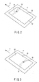
- For example, labels as shown in FIG. 2 and FIG. 3 are available for RFID. In FIG. 2, a
reference numeral 11 denotes a liner, and 12 denotes a label. AnRFID tag 13 is placed between theliner 11 andlabel 12. TheRFID tag 13 is comprised of anRFID antenna 14 and anRFID chip 15. - Explanation will be given on writing data in the
RFID chip 15 and printing on thelabel 12 by using a printer. When the print head of a printer is at the home position, theRFID chip 15 is displaced from the suitable position of the RFID read/write unit to write data. Thus, feed the label first, and move theRFID chip 15 from the FRID read/write unit to the suitable position, and write data on theRFID chip 15. Then, feed the label again to the position suitable for printing the label by the print head. - The position of burying the
RFID chip 15 in thelabel 12 is different according to the kinds of RFID tag, and the amount of feeding the label in the label feeding direction is different when writing data on theRFID chip 15. - If the feed amount is not optimum, writing data in the
RFID chip 15 and printing data on thelabel 12 may fail. - It is an object of the present invention is to provide a program stored in a medium readable by a computer for measuring optimum feed amount to an RFID antenna capable of obtaining an optimum value of feeding an RFID label in a label feeding direction, a feed amount measuring method, and a printer having an RFID read/write function.
- According to one aspect of the invention, there is provided a program stored in a medium readable by a computer for measuring an optimum feed amount to an RFID antenna from a print standby position of a printer which reads and writes data on/from an RFID tag by feeding a label or tag containing an RFID tag, and then prints on the label surface by feeding the label or tag in the reverse direction, comprising testing the RFID tag for reading/writing whenever the label or tag is fed by a fixed feed amount from a print standby position, and outputting the result of the read/write test visibly.
- This summary of the invention does not necessarily describe all necessary features so that the invention may also be a sub-combination of these described features.
- The invention can be more fully understood from the following detailed description when taken in conjunction with the accompanying drawings, in which:
- FIG. 1 is a block diagram of the configuration of a printer having an RFID read/write function according to an embodiment of the present invention;
- FIG. 2 is a view showing an RFID label according to the same embodiment;
- FIG. 3 is a view showing another RFID label according to the same embodiment;
- FIG. 4 is a view showing the configuration of the RFID label of FIG. 2;
- FIG. 5 is a view showing the configuration of the RFID label of FIG. 3;
- FIG. 6 is a flowchart for explaining the operation of the same embodiment;
- FIG. 7 is a graph for explaining the operation of the same embodiment; and
- FIG. 8 is another graph for explaining the operation of the same embodiment.
- Am embodiment of the present invention will be explained hereinafter with reference to the accompanying drawings. First, explanation will be give on the system configuration of a printer having the RFID read/write function with reference to the block diagram of FIG. 1.
- In FIG. 1, a
reference numeral 21 denotes a CPU (Central Processing Unit) to perform centralized control of the printer. Asystem bus 21a from theCPU 21 is connected to a flash ROM (Read Only Memory) 22, a RAM (Random Access Memory) 23, aninput unit 24, aprint head controller 25, adisplay 26, a feeding means 27, an RFID read/writeunit 28, and aninterface 29. - A
print head 31 is connected to theprint controller 25. Theinterface 29 is connected to apersonal computer 32. Theinterface 29 serves as a means of taking in a feed amount described later. The configuration of thepersonal computer 32 is well known, and detailed explanation will be omitted. Thepersonal computer 32 has a flash ROM 32f, a RAM 32m, a display 32d, and input unit 32i. The operator can instruct to issue a label or tag from the input unit 21i. - The
flash ROM 22 stores various control programs necessary for operating the printer. - The
RAM 23 ensures a work area used by the various control programs. - The
print head controller 25 outputs a driving signal to theprint head 31 composed of a thermal head, for example. - The
display 26 is composed of a liquid crystal display, for example. - The feeding means 27 is composed of a stepping motor, a
platen 42 and a feeding roller, which feed theliner 11. - Next, kinds of RFID will be explained with reference to FIG. 2 and FIG. 3. The RFID tag of FIG. 2 is as explained in the prior art.
- The configuration of the RFID tag of FIG. 3 will be explained. In FIG. 3, the same numbers are given to the same components of FIG. 2, and detailed explanation will be omitted. The RFID tag shown in FIG. 3 is buried in the upstream of the RFID tag of FIG. 2 in the feeding direction (indicated by the arrow X).
- Next, explanation will be given on the essential part of the configuration of the printer having the RFID read/write function with reference to FIG. 4.
- In FIG. 4, a
reference numeral 41 denotes a feeding path to feed theliner 11. Theliner 11 is fed on thefeeding path 41 by the feeding means 27. - A
reference numeral 42 denotes a platen. The RFID read/writeunit 28 is provided on the upstream of theplaten 42. - The
print head 31 is placed opposite to theplaten 42 through thefeeding path 41. - On the upstream of the
print head 31, asupply roller 44 to supply anink ribbon 43 is provided. On the downstream of theprint head 31, a take-up roller 45 to take up theink ribbon 43 is provided. - FIG. 4 shows the position of the RFID tag of FIG. 2 when the
print head 31 comes to the home position. In theRFID tag 13 of FIG. 2, theRFID antenna 14 andRFID chip 15 are buried close to theprint head 31 in thelabel 12. Therefore, theRFID antenna 14 andRFID chip 15 are placed substantially over the RFID read/writeunit 28. - FIG. 5 shows the position of the RFID tag of FIG. 3 when the
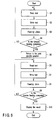
print head 31 comes to the home position. In theRFID tag 13 of FIG. 3, theRFID antenna 14 andRFID chip 15 are buried in the upstream of the RFID tag of FIG. 2 in the feeding direction (indicated by the arrow X). Therefore, theRFID antenna 14 andRFID chip 15 are buried in the upstream of the RFID read/write unit in the feeding direction (indicated by the arrow X). - Next, explanation will be given on the operation of an embodiment of the invention with reference to the flowchart of FIG. 6. A program for performing the operation shown in the flowchart of FIG. 6 is stored in a recording medium 33 (e.g., CD-ROM) readable by a computer. The program stored in the
recording medium 33 is downloaded into the flash ROM 32f of thepersonal computer 32. - First, a read test is performed at the print standby position shown in FIG. 4 (step S1). The read test is a judgment whether specified data stored in the
RFID chip 15 can be successfully read or not. - The result of the read test is stored in the memory 32m of the
personal computer 32. - Then, a write test is performed (step S2). The write test is a judgment which judges that data is successfully written when the RFID read/write unit 28a receives a signal, which means that data is written to the
RFID chip 15, from theRFID chip 15. - The result of the read test is stored in the memory 32m of the
personal computer 32. - Then, the feeding means 27 feeds the
label 12 by +5mm forward, that is, toward the print head 31 (step S3). "+" means the feeding direction indicated by the arrow X shown in FIG. 4. - Whether the forward feeding is completed is judged (step S4). The feed amount is determined by considering the characteristic of the stepping motor composing the feeding means 27.
- When NO in step S4, the operations on and after S1 are repeated. Namely, until the forward feeding is completed, the operations to read and write the data from/in the
RFID chip 15 are repeated. - In this embodiment, the operations to read and write the data in the forward direction are repeated by 100 times.
- When YES in step S5, the feeding means 27 feeds the
label 12 in the reverse direction to return to the print standby position (step S4). - At the print standby position, the read test is performed (step S6). And then, the write test is performed (step S7).
- Then, the feeding means 27 feeds the
label 12 by 5mm in the direction reverse to theprint head 31, that is, by -5mm. - Then, whether the reverse feeding is completed is judged (step S9). Until YES is judged in step S9, the operations of steps S6 - S8 are repeated. In this embodiment, the read and write tests in the reverse direction are repeated by 100 times. The results of the tests are stored in the memory 32m of the
personal computer 32. - When YES is judged in step S9, the test results of the tests are displayed in the display 32d as shown in FIG. 7.
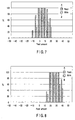
- Next, explanation will be given on the results of the tests displayed in the display 32d of the
personal computer 32 with referent to FIG. 7. In FIG. 7, a sign A indicates the read test, and a sign B indicates the write test. - As shown in FIG. 7, the reading and writing are 100% successful in the feed amount 0 - 10. When the feed amount is increased to 15 and 20, the reading and writing are not 100% successful.
- When the feed amount is decreased to -5 to -10, the reading and writing are 100% unsuccessful.
- It is seen from FIG. 2 that when the feed amount is close to 0, the reading and writing are 100% successful. Therefore, an optimum feed amount is set to 0.
- Because, when the
RFID tag 13 is at the print standby position, theRFID chip 15 is placed over the RFID read/write unit 28. - FIG. 8 shows the state that the results of similar tests performed by using the RFID tag shown in FIG. 3 are displayed in the display of the
personal computer 32. - As seen from this graph, when the feed amount is in a range of +20 to +30, the reading and writing are 100% successful. In this case, an optimum feed amount may be set to +25.
- As explained above, by loading the programs for performing the operations shown in the flowchart of FIG. 6 in the
personal computer 32, an optimum feed amount of the printer can be obtained. - It is also permitted to store an optimum feed amount in the RAM 32m of the
personal computer 32. The apparatus may be so configured that when an issue command is entered from thepersonal computer 32, thepersonal computer 32 sends the command to the printer through theinterface 29. Receiving the command, the printer feeds the label or tag according to the feed amount, and performs printing (an issuing means). - In the embodiment described above, the programs for performing the operations of the flowchart of FIG. 6 are loaded in the
personal computer 32. The programs for performing the operations of the flowchart of FIG. 6 may be loaded in theflash ROM 22. - Further, although the test result is displayed in the display 32d of the
personal computer 32, the result may be displayed in thedisplay 26 of the printer or may be printed on thelabel 11. - It is explicitly stated that all features disclosed in the description and/or the claims are intended to be disclosed separately and independently from each other for the purpose of original disclosure as well as for the purpose of restricting the claimed invention independent of the composition of the features in the embodiments and/or the claims. It is explicitly stated that all value ranges or indications of groups of entities disclose every possible intermediate value or intermediate entity for the purpose of original disclosure as well as for the purpose of restricting the claimed invention, in particular as limits of value ranges.
Claims (15)
- A method of measuring an optimum feed amount to an RFID antenna from a print standby position of a printer which reads and writes data from/on an RFID tag by feeding a label or tag containing an RFID tag, and then prints on the label surface by feeding the label or tag in the reverse direction, characterized by comprising steps of:testing (S1, S2, S6, S7) the RFID tag for reading/writing whenever the label or tag is fed by a fixed feed amount from a print standby position, andoutputting (S10) the result of the read/write test visibly.
- The method according to claim 1, characterized in that
testing the RFID tag for reading is judgment whether specified data stored in the tag can be successfully read or not and testing the RFID tag for writing is a judgment which judges that data is successfully written when receiving a signal, which means that data is written to the RFID tag, from the RFID tag. - A method of measuring an optimum feed amount to an RFID antenna from a print standby position of a printer which reads and writes data from/on an RFID tag by feeding a label or tag containing an RFID tag, and then prints on the label surface by feeding the label or tag in the reverse direction, characterized by comprising steps of:testing (S1, S6) the RFID tag for reading whenever the label or tag is fed by a fixed feed amount from a print standby position, andoutputting (S10) the result of the read test visibly.
- The method according to claim 3, characterized in that
testing the RFID tag for reading is judgment whether specified data stored in the tag can be successfully read or not. - A method of measuring an optimum feed amount to an RFID antenna from a print standby position of a printer which reads and writes data from/on an RFID tag by feeding a label or tag containing an RFID tag, and then prints on the label surface by feeding the label or tag in the reverse direction, characterized by comprising step of:testing (S2, S7) the RFID tag for writing whenever the label or tag is fed by a fixed feed amount from a print standby position, andoutputting (S10) the result of the write test visibly.
- The method according to claim 5, characterized in that testing the RFID tag for writing is a judgment which judges that data is successfully written when receiving a signal, which means that data is written to the RFID tag, from the RFID tag.
- A printer having an RFID read/write function to read/write an RFID tag of a label or tag containing an RFID tag, and print on the surface of the label or tag, characterized by comprising:a test unit for performing a read/write test to the RFID tag whenever the label or tag is fed by a fixed amount from a print standby position; anda output device for outputting the result of the read/write test visibly.
- The printer according to claim 7, characterized in that the test unit tests the RFID tag for reading is judgment whether specified data stored in the tag can be successfully read or not and tests the RFID tag for writing is a judgment which judges that data is successfully written when receiving a signal, which means that data is written to the RFID tag, from the RFID tag.
- A printer having an RFID read/write function to read/write an RFID tag of a label or tag containing an RFID tag, and print on the surface of the label or tag, characterized by comprising:a test unit (28) for performing a read test to the RFID tag whenever the label or tag is fed by a fixed amount from a print standby position; anda output device (32d) for outputting the result of the read test visibly.
- The printer according to claim 9, characterized in that the test unit tests the RFID tag for reading is judgment whether specified data stored in the tag can be successfully read or not.
- A printer having an RFID read/write function to read/write an RFID tag of a label or tag containing an RFID tag, and print on the surface of the label or tag, characterized by comprising:a test unit (28) for performing a write test to the RFID tag whenever the label or tag is fed by a fixed amount from a print standby position; anda output device (32d) for outputting the result of the write test visibly.
- The printer according to claim 11, characterized in that the test unit tests the RFID tag for writing is a judgment which judges that data is successfully written when receiving a signal, which means that data is written to the RFID tag, from the RFID tag.
- A printer having an RFID read/write function to read/write an RFID tag of a label or tag containing an RFID tag, and print on the surface of the label or tag, characterized by comprising:a read/write unit (28) for reading and writing from/in the RFID tag whenever the label or tag is fed by a fixed amount from a print standby position;a take-in unit (29) for taking in the feed amount based on the results of the reading and writing; andan issue unit (22) for feeding the label or tag based on the feed amount taken in by the take-in unit, and performs printing, when a command to issue a label or tag is received.
- The printer according to claim 13, characterized in that printing on the surface of the label or tag is performed by a thermal printer.
- The printer according to claim 14, characterized in that printing is performed by transferring ink of a ink ribbon to a paper.
Applications Claiming Priority (1)
| Application Number | Priority Date | Filing Date | Title |
|---|---|---|---|
| JP2004376325A JP2006181800A (en) | 2004-12-27 | 2004-12-27 | Feed amount measurement program, feed amount measurement method, and printer having RFID read / write function |
Publications (3)
| Publication Number | Publication Date |
|---|---|
| EP1675039A2 true EP1675039A2 (en) | 2006-06-28 |
| EP1675039A3 EP1675039A3 (en) | 2007-11-07 |
| EP1675039B1 EP1675039B1 (en) | 2010-05-26 |
Family
ID=36168840
Family Applications (1)
| Application Number | Title | Priority Date | Filing Date |
|---|---|---|---|
| EP05027908A Expired - Lifetime EP1675039B1 (en) | 2004-12-27 | 2005-12-20 | Program stored in medium readable by computer for measuring optimum feed amount to RFID antenna, feed amount measuring method, and printer having RFID read/write function |
Country Status (5)
| Country | Link |
|---|---|
| US (1) | US7679515B2 (en) |
| EP (1) | EP1675039B1 (en) |
| JP (1) | JP2006181800A (en) |
| CN (1) | CN1818931B (en) |
| DE (1) | DE602005021448D1 (en) |
Cited By (1)
| Publication number | Priority date | Publication date | Assignee | Title |
|---|---|---|---|---|
| WO2012005855A1 (en) * | 2010-06-29 | 2012-01-12 | Premark Feg L.L.C. | Printer and scale with initialization process for selecting rfid frequency band for communicating with rfid labels |
Families Citing this family (16)
| Publication number | Priority date | Publication date | Assignee | Title |
|---|---|---|---|---|
| US7479870B2 (en) * | 2006-04-10 | 2009-01-20 | Dell Products L.P. | Method and apparatus for programming a transponder |
| JP4206109B2 (en) * | 2006-07-31 | 2009-01-07 | 東芝テック株式会社 | Wireless tag reader |
| US8820639B2 (en) * | 2006-11-03 | 2014-09-02 | Assa Abloy Ab | Security feature RFID card |
| JP5107876B2 (en) * | 2008-12-04 | 2012-12-26 | 東芝テック株式会社 | Wireless communication apparatus and wireless communication method |
| JP4766125B2 (en) * | 2009-02-18 | 2011-09-07 | ブラザー工業株式会社 | Image processing device |
| JP5538491B2 (en) | 2012-08-02 | 2014-07-02 | 東芝テック株式会社 | RFID label printer and method for controlling RFID label printer |
| JP5465286B2 (en) | 2012-08-02 | 2014-04-09 | 東芝テック株式会社 | RFID label printer and method for controlling RFID label printer |
| CN104044355B (en) * | 2013-03-12 | 2016-12-28 | 山东新北洋信息技术股份有限公司 | There is printing equipment and the control method thereof of RFID read-write function |
| JP6188454B2 (en) * | 2013-06-28 | 2017-08-30 | キヤノン株式会社 | Printing apparatus, control method therefor, and program |
| CN105751707B (en) * | 2015-07-03 | 2018-05-25 | 昆山祥维电子科技有限公司 | A kind of passive RFID visible card printer |
| GB2549109A (en) * | 2016-04-05 | 2017-10-11 | Dover Europe Sàrl | Identification method |
| CN108256601B (en) * | 2018-01-15 | 2020-11-06 | 重庆品胜科技有限公司 | RFID label printing method, printing method and device of label printer and label printer |
| JP7108469B2 (en) * | 2018-06-01 | 2022-07-28 | 東芝テック株式会社 | Wireless tag writing device, wireless tag writing method and program |
| CN110902071A (en) * | 2019-12-23 | 2020-03-24 | 上海工业自动化仪表研究院有限公司 | RFID automatic labeling device |
| US12108000B1 (en) * | 2023-03-31 | 2024-10-01 | Hand Held Products, Inc. | Methods, apparatuses, and computer program products for calibrating radio-frequency identification (RFID) printers |
| CN121745132B (en) * | 2026-02-26 | 2026-05-15 | 北京硕方信息技术有限公司 | Automatic calibration method and device for antenna read/write power and position of RFID tag printer |
Family Cites Families (7)
| Publication number | Priority date | Publication date | Assignee | Title |
|---|---|---|---|---|
| US6019865A (en) * | 1998-01-21 | 2000-02-01 | Moore U.S.A. Inc. | Method of forming labels containing transponders |
| JP4541465B2 (en) * | 1998-09-10 | 2010-09-08 | ミルストーン トランスファー エージー、エル.エル.シー. | Electronic tag, electronic tag identification system |
| JP2001096814A (en) | 1999-09-29 | 2001-04-10 | Toshiba Tec Corp | Printer with RF-ID reading / writing device |
| JP3831581B2 (en) * | 2000-06-21 | 2006-10-11 | 東芝テック株式会社 | Printer with RF-ID read / write function |
| JP2003296669A (en) | 2002-04-08 | 2003-10-17 | Canon Finetech Inc | RF-ID communication device, recording device, program, control method, wireless communication system |
| GB2395593B (en) * | 2002-11-21 | 2007-05-16 | Hewlett Packard Co | Apparatus for printing,data writing to memory tags and data reading from memory tags, and methods therefor |
| US20060145859A1 (en) * | 2004-12-17 | 2006-07-06 | Joshua Posamentier | RFID antenna assembly with integrated status indicator |
-
2004
- 2004-12-27 JP JP2004376325A patent/JP2006181800A/en active Pending
-
2005
- 2005-12-20 DE DE602005021448T patent/DE602005021448D1/en not_active Expired - Lifetime
- 2005-12-20 EP EP05027908A patent/EP1675039B1/en not_active Expired - Lifetime
- 2005-12-21 US US11/314,469 patent/US7679515B2/en not_active Expired - Fee Related
- 2005-12-27 CN CN200510135632XA patent/CN1818931B/en not_active Expired - Fee Related
Cited By (2)
| Publication number | Priority date | Publication date | Assignee | Title |
|---|---|---|---|---|
| WO2012005855A1 (en) * | 2010-06-29 | 2012-01-12 | Premark Feg L.L.C. | Printer and scale with initialization process for selecting rfid frequency band for communicating with rfid labels |
| US8537394B2 (en) | 2010-06-29 | 2013-09-17 | Premark Feg L.L.C. | Printer and scale with initialization process for selecting RFID frequency band for communicating with RFID labels |
Also Published As
| Publication number | Publication date |
|---|---|
| JP2006181800A (en) | 2006-07-13 |
| DE602005021448D1 (en) | 2010-07-08 |
| CN1818931B (en) | 2010-10-06 |
| EP1675039B1 (en) | 2010-05-26 |
| EP1675039A3 (en) | 2007-11-07 |
| CN1818931A (en) | 2006-08-16 |
| US20060139662A1 (en) | 2006-06-29 |
| US7679515B2 (en) | 2010-03-16 |
Similar Documents
| Publication | Publication Date | Title |
|---|---|---|
| EP1675039B1 (en) | Program stored in medium readable by computer for measuring optimum feed amount to RFID antenna, feed amount measuring method, and printer having RFID read/write function | |
| KR101130595B1 (en) | Printing system | |
| US10467513B2 (en) | Verification of a printed image on media | |
| US8410912B2 (en) | Printing device | |
| US20160188921A1 (en) | Reduce inlay pitch singulation | |
| CN111055598B (en) | Method and apparatus for RFID devices | |
| US8867087B2 (en) | Printing apparatus, printing system, and printing control method for printing a watermark on a receipt along with print data sent from a host apparatus | |
| JP4492663B2 (en) | Writing device and label production system | |
| JP2006116886A (en) | Printer | |
| EP1674272A1 (en) | Printer having RFID read/write function | |
| US20190126651A1 (en) | Printer apparatus, printing method, and computer readable medium | |
| EP0397200B1 (en) | Printer apparatus | |
| JP2005047231A (en) | Printing device | |
| JPH05205084A (en) | Bar code printer | |
| JPH0781099A (en) | Thermal recorder | |
| US20230302821A1 (en) | Printing system | |
| JP2026059154A (en) | Printing system | |
| EP1385113A2 (en) | Method of detecting bad dots in bar code print zone | |
| JP2006272842A (en) | Printing device | |
| JPH05221075A (en) | Printer | |
| HK1236483A1 (en) | Reduce inlay pitch singulation |
Legal Events
| Date | Code | Title | Description |
|---|---|---|---|
| PUAI | Public reference made under article 153(3) epc to a published international application that has entered the european phase |
Free format text: ORIGINAL CODE: 0009012 |
|
| 17P | Request for examination filed |
Effective date: 20051220 |
|
| AK | Designated contracting states |
Kind code of ref document: A2 Designated state(s): AT BE BG CH CY CZ DE DK EE ES FI FR GB GR HU IE IS IT LI LT LU LV MC NL PL PT RO SE SI SK TR |
|
| AX | Request for extension of the european patent |
Extension state: AL BA HR MK YU |
|
| PUAL | Search report despatched |
Free format text: ORIGINAL CODE: 0009013 |
|
| AK | Designated contracting states |
Kind code of ref document: A3 Designated state(s): AT BE BG CH CY CZ DE DK EE ES FI FR GB GR HU IE IS IT LI LT LU LV MC NL PL PT RO SE SI SK TR |
|
| AX | Request for extension of the european patent |
Extension state: AL BA HR MK YU |
|
| 17Q | First examination report despatched |
Effective date: 20080521 |
|
| AKX | Designation fees paid |
Designated state(s): BE DE ES FR GB NL |
|
| GRAP | Despatch of communication of intention to grant a patent |
Free format text: ORIGINAL CODE: EPIDOSNIGR1 |
|
| GRAS | Grant fee paid |
Free format text: ORIGINAL CODE: EPIDOSNIGR3 |
|
| GRAA | (expected) grant |
Free format text: ORIGINAL CODE: 0009210 |
|
| AK | Designated contracting states |
Kind code of ref document: B1 Designated state(s): BE DE ES FR GB NL |
|
| REG | Reference to a national code |
Ref country code: GB Ref legal event code: FG4D |
|
| REF | Corresponds to: |
Ref document number: 602005021448 Country of ref document: DE Date of ref document: 20100708 Kind code of ref document: P |
|
| REG | Reference to a national code |
Ref country code: NL Ref legal event code: VDEP Effective date: 20100526 |
|
| PG25 | Lapsed in a contracting state [announced via postgrant information from national office to epo] |
Ref country code: NL Free format text: LAPSE BECAUSE OF FAILURE TO SUBMIT A TRANSLATION OF THE DESCRIPTION OR TO PAY THE FEE WITHIN THE PRESCRIBED TIME-LIMIT Effective date: 20100526 |
|
| PG25 | Lapsed in a contracting state [announced via postgrant information from national office to epo] |
Ref country code: BE Free format text: LAPSE BECAUSE OF FAILURE TO SUBMIT A TRANSLATION OF THE DESCRIPTION OR TO PAY THE FEE WITHIN THE PRESCRIBED TIME-LIMIT Effective date: 20100526 |
|
| PLBE | No opposition filed within time limit |
Free format text: ORIGINAL CODE: 0009261 |
|
| STAA | Information on the status of an ep patent application or granted ep patent |
Free format text: STATUS: NO OPPOSITION FILED WITHIN TIME LIMIT |
|
| 26N | No opposition filed |
Effective date: 20110301 |
|
| REG | Reference to a national code |
Ref country code: DE Ref legal event code: R097 Ref document number: 602005021448 Country of ref document: DE Effective date: 20110228 |
|
| GBPC | Gb: european patent ceased through non-payment of renewal fee |
Effective date: 20101220 |
|
| REG | Reference to a national code |
Ref country code: FR Ref legal event code: ST Effective date: 20110831 |
|
| PG25 | Lapsed in a contracting state [announced via postgrant information from national office to epo] |
Ref country code: FR Free format text: LAPSE BECAUSE OF NON-PAYMENT OF DUE FEES Effective date: 20110103 |
|
| PG25 | Lapsed in a contracting state [announced via postgrant information from national office to epo] |
Ref country code: GB Free format text: LAPSE BECAUSE OF NON-PAYMENT OF DUE FEES Effective date: 20101220 Ref country code: DE Free format text: LAPSE BECAUSE OF NON-PAYMENT OF DUE FEES Effective date: 20110701 |
|
| REG | Reference to a national code |
Ref country code: DE Ref legal event code: R119 Ref document number: 602005021448 Country of ref document: DE Effective date: 20110701 |
|
| PG25 | Lapsed in a contracting state [announced via postgrant information from national office to epo] |
Ref country code: ES Free format text: LAPSE BECAUSE OF FAILURE TO SUBMIT A TRANSLATION OF THE DESCRIPTION OR TO PAY THE FEE WITHIN THE PRESCRIBED TIME-LIMIT Effective date: 20100906 |