EP1674718B1 - Système d'injection accumulateur pour moteur a combustion interne - Google Patents
Système d'injection accumulateur pour moteur a combustion interne Download PDFInfo
- Publication number
- EP1674718B1 EP1674718B1 EP04425945A EP04425945A EP1674718B1 EP 1674718 B1 EP1674718 B1 EP 1674718B1 EP 04425945 A EP04425945 A EP 04425945A EP 04425945 A EP04425945 A EP 04425945A EP 1674718 B1 EP1674718 B1 EP 1674718B1
- Authority
- EP
- European Patent Office
- Prior art keywords
- fuel
- pumping element
- injection system
- solenoid valve
- volume
- Prior art date
- Legal status (The legal status is an assumption and is not a legal conclusion. Google has not performed a legal analysis and makes no representation as to the accuracy of the status listed.)
- Active
Links
- 239000000446 fuel Substances 0.000 title claims abstract description 67
- 238000002347 injection Methods 0.000 title claims abstract description 49
- 239000007924 injection Substances 0.000 title claims abstract description 49
- 238000002485 combustion reaction Methods 0.000 title claims description 8
- 238000005086 pumping Methods 0.000 claims abstract description 54
- 230000006835 compression Effects 0.000 claims abstract description 29
- 238000007906 compression Methods 0.000 claims abstract description 29
- 238000012384 transportation and delivery Methods 0.000 claims abstract description 24
- 238000000034 method Methods 0.000 claims description 6
- 230000003213 activating effect Effects 0.000 claims description 2
- 230000001276 controlling effect Effects 0.000 description 3
- 230000001105 regulatory effect Effects 0.000 description 3
- 230000005540 biological transmission Effects 0.000 description 2
- 239000012530 fluid Substances 0.000 description 2
- 239000012071 phase Substances 0.000 description 2
- PCTMTFRHKVHKIS-BMFZQQSSSA-N (1s,3r,4e,6e,8e,10e,12e,14e,16e,18s,19r,20r,21s,25r,27r,30r,31r,33s,35r,37s,38r)-3-[(2r,3s,4s,5s,6r)-4-amino-3,5-dihydroxy-6-methyloxan-2-yl]oxy-19,25,27,30,31,33,35,37-octahydroxy-18,20,21-trimethyl-23-oxo-22,39-dioxabicyclo[33.3.1]nonatriaconta-4,6,8,10 Chemical compound C1C=C2C[C@@H](OS(O)(=O)=O)CC[C@]2(C)[C@@H]2[C@@H]1[C@@H]1CC[C@H]([C@H](C)CCCC(C)C)[C@@]1(C)CC2.O[C@H]1[C@@H](N)[C@H](O)[C@@H](C)O[C@H]1O[C@H]1/C=C/C=C/C=C/C=C/C=C/C=C/C=C/[C@H](C)[C@@H](O)[C@@H](C)[C@H](C)OC(=O)C[C@H](O)C[C@H](O)CC[C@@H](O)[C@H](O)C[C@H](O)C[C@](O)(C[C@H](O)[C@H]2C(O)=O)O[C@H]2C1 PCTMTFRHKVHKIS-BMFZQQSSSA-N 0.000 description 1
- 238000010586 diagram Methods 0.000 description 1
- 238000005516 engineering process Methods 0.000 description 1
- 239000002828 fuel tank Substances 0.000 description 1
- 239000007788 liquid Substances 0.000 description 1
- 239000007791 liquid phase Substances 0.000 description 1
Images

Classifications
-
- F—MECHANICAL ENGINEERING; LIGHTING; HEATING; WEAPONS; BLASTING
- F02—COMBUSTION ENGINES; HOT-GAS OR COMBUSTION-PRODUCT ENGINE PLANTS
- F02M—SUPPLYING COMBUSTION ENGINES IN GENERAL WITH COMBUSTIBLE MIXTURES OR CONSTITUENTS THEREOF
- F02M63/00—Other fuel-injection apparatus having pertinent characteristics not provided for in groups F02M39/00 - F02M57/00 or F02M67/00; Details, component parts, or accessories of fuel-injection apparatus, not provided for in, or of interest apart from, the apparatus of groups F02M39/00 - F02M61/00 or F02M67/00; Combination of fuel pump with other devices, e.g. lubricating oil pump
- F02M63/02—Fuel-injection apparatus having several injectors fed by a common pumping element, or having several pumping elements feeding a common injector; Fuel-injection apparatus having provisions for cutting-out pumps, pumping elements, or injectors; Fuel-injection apparatus having provisions for variably interconnecting pumping elements and injectors alternatively
- F02M63/0225—Fuel-injection apparatus having a common rail feeding several injectors ; Means for varying pressure in common rails; Pumps feeding common rails
-
- F—MECHANICAL ENGINEERING; LIGHTING; HEATING; WEAPONS; BLASTING
- F02—COMBUSTION ENGINES; HOT-GAS OR COMBUSTION-PRODUCT ENGINE PLANTS
- F02D—CONTROLLING COMBUSTION ENGINES
- F02D41/00—Electrical control of supply of combustible mixture or its constituents
- F02D41/30—Controlling fuel injection
- F02D41/38—Controlling fuel injection of the high pressure type
- F02D41/3809—Common rail control systems
- F02D41/3836—Controlling the fuel pressure
- F02D41/3845—Controlling the fuel pressure by controlling the flow into the common rail, e.g. the amount of fuel pumped
-
- F—MECHANICAL ENGINEERING; LIGHTING; HEATING; WEAPONS; BLASTING
- F02—COMBUSTION ENGINES; HOT-GAS OR COMBUSTION-PRODUCT ENGINE PLANTS
- F02M—SUPPLYING COMBUSTION ENGINES IN GENERAL WITH COMBUSTIBLE MIXTURES OR CONSTITUENTS THEREOF
- F02M59/00—Pumps specially adapted for fuel-injection and not provided for in groups F02M39/00 -F02M57/00, e.g. rotary cylinder-block type of pumps
- F02M59/20—Varying fuel delivery in quantity or timing
- F02M59/34—Varying fuel delivery in quantity or timing by throttling of passages to pumping elements or of overflow passages, e.g. throttling by means of a pressure-controlled sliding valve having liquid stop or abutment
-
- F—MECHANICAL ENGINEERING; LIGHTING; HEATING; WEAPONS; BLASTING
- F02—COMBUSTION ENGINES; HOT-GAS OR COMBUSTION-PRODUCT ENGINE PLANTS
- F02M—SUPPLYING COMBUSTION ENGINES IN GENERAL WITH COMBUSTIBLE MIXTURES OR CONSTITUENTS THEREOF
- F02M59/00—Pumps specially adapted for fuel-injection and not provided for in groups F02M39/00 -F02M57/00, e.g. rotary cylinder-block type of pumps
- F02M59/20—Varying fuel delivery in quantity or timing
- F02M59/36—Varying fuel delivery in quantity or timing by variably-timed valves controlling fuel passages to pumping elements or overflow passages
- F02M59/366—Valves being actuated electrically
Definitions
- the present invention relates to an internal combustion engine storage-volume fuel injection system (EP-A-1219827).
- Modern internal combustion engine fuel injection systems normally comprise a pump for supplying high-pressure fuel to a common rail having a given fuel storage volume and for supplying a number of engine cylinder injectors.
- the pump comprises at least one reciprocating pumping element performing each time an intake stroke and a compression or delivery stroke.
- the fuel must be brought to extremely high pressure, e.g. in the region of 1600 bars in maximum engine load conditions.
- Current regulations governing pollution by engine exhaust gas require that the fuel feed pressure to the injectors be reproducible as accurately as possible with respect to the electronic central control unit map.
- Pressure fluctuations, in the common rail, with respect to the set pressure can be limited if the volume of the common rail is over order of magnitude of the fuel quantity drawn by each injector per combustion cycle.
- Such a common rail is invariably bulky and therefore difficult to accommodate on the engine.
- each pumping element has an instantaneous flow, the maximum value of which is less than the maximum value of each injector, so that, during each injection, only part of the injected fuel, about 20%, is normally supplied by the pump, the rest being supplied by the common rail.
- Systems of this sort therefore have the drawback of necessarily requiring a common rail of suitable size.
- the pump operates permanently at the maximum flow rate, while the bypass solenoid valves simply provides for draining the surplus pumped fuel, in excess of that drawn by the injectors, into the tank, thus dissipating heat.
- the flow control device comprises an on-off solenoid valve along the intake conduit of the pumping element, the maximum instantaneous flow of which is greater than the maximum flow of each injector, and the solenoid valve is controlled by a chopper control unit synchronously with the intake stroke.
- the chopper control unit provides for pulse-width-modulation (PWM) control of the on-off solenoid valve with a pumping element intake start instant and end instant, so as to control the fuel volume fed into the compression chamber by modulating both the instant the solenoid valve opens and the instant it closes.
- PWM pulse-width-modulation
- the invention also relates to a method of controlling the fuel pressure in a storage volume for a number of fuel injectors, as claimed in Claim 9.
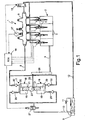
- Number 1 in Figure 1 indicates as a whole a common-rail fuel injection system for an internal combustion, e.g. diesel, engine 2 comprising a number of, e.g. four, cylinders 3, which cooperate with corresponding pistons (not shown) for rotating a drive shaft 4.
- an internal combustion e.g. diesel
- engine 2 comprising a number of, e.g. four, cylinders 3, which cooperate with corresponding pistons (not shown) for rotating a drive shaft 4.
- Injection system 1 comprises a number of electrically controlled injectors 5 associated with and for injecting high-pressure fuel into cylinders 3. Injectors 5 are connected to a storage volume having a given volume for one or more injectors 5.
- the storage volume is defined by a common rail 6, to which injectors 5 are all connected, and which is supplied by a high-pressure pump, indicated as a whole by 7, with high-pressure fuel along a high-pressure delivery conduit 8.
- the storage volume may also be distributed in the pump delivery conduit 8 to injectors 5.
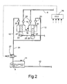
- High-pressure pump 7 is in turn supplied by a low-pressure pump, e.g. a motor-driven pump 9, along a low-pressure fuel intake conduit 10.
- Motor-driven pump 9 is normally located in the fuel tank 11, to which a surplus-fuel drain conduit 12 of injection system 1 is connected. Drain conduit 12 drains into tank 11 both the surplus fuel drained by injectors 5, and any surplus fuel drained by common rail 6 when pressure exceeds that defined by a solenoid regulating valve 15.
- a regulating device comprising at least one on-off solenoid valve 27 is located between motor-driven pump 9 and high-pressure pump 7.
- the fuel in tank 11 is at atmospheric pressure.
- motor-driven pump 9 compresses the fuel to a low pressure, e.g. of around 2-3 bars; and high-pressure pump 7 compresses the incoming fuel from intake conduit 10 to supply high-pressure fuel, e.g. of about 1600 bars, along delivery conduit 8 to common rail 6.
- Each injector 5 is activated to inject corresponding cylinder 3 with a variable amount of fuel, i.e. ranging between a minimum and maximum value, under the control of an electronic control unit 16, which may be defined by the central microprocessor control unit of engine 2.
- Control unit 16 receives signals indicating the operating conditions of engine 2, such as the accelerator pedal position and the speed of drive shaft 4, which are detected by corresponding sensors, and the fuel pressure in common rail 6 as detected by a pressure sensor 17. Control unit 16 processes the incoming signals by means of a special program to control when and for how long individual injectors 5 are to operate, as well as solenoid regulating valve 15.
- High-pressure pump 7 comprises one or more reciprocating pumping elements 18, each defined by a cylinder 19 having a compression chamber 20, in which a piston 21 slides.
- Compression chamber 20 communicates with intake conduit 10 via an intake valve 25, and communicates with delivery conduit 8 via a delivery valve 30.
- Piston 21 is activated, by cam means 22 fitted to a shaft 23, to perform a reciprocating sinusoidal movement comprising an intake stroke and a compression or delivery stroke, as explained in detail later on.
- shaft 23 is connected to the drive shaft 4 by a transmission device 26, so that a compression stroke is performed for each injection by injectors 5 into respective cylinders 3.
- Shaft 23 may be defined by a shaft for also operating other devices of engine 2.
- pump 7 normally comprises a number of pumping elements 18, which may be activated by a common cam.
- pump 7 comprises two diametrically opposite pumping elements 18 activated by a common cam 22.
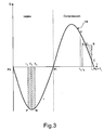
- the x axis shows the intake stroke Ps-Pi and the compression stroke Pi-Ps of a pumping element 18.
- the speed of pumping element 18 is shown by a sinusoidal curve 24, which therefore also represents the instantaneous flow Q of pumping element 18 in the absence of on-off solenoid valve 27.
- the area subtended by curve 24 therefore represents the maximum fuel intake/delivery volume for each pump stroke.
- Operation of an injector 5 for each injection into respective cylinder 3 is represented by a rectangle I 0 ABI 1 , the base of which on the x axis is a segment between a start point I 0 and an end point I 1 , and the height of which indicates the instantaneous flow (here assumed constant) of injector 5.
- the area of rectangle I 0 ABI 1 therefore represents the volume of fuel delivered by injector 5 at the injection stage, and which varies both in duration, by varying the position of points I 0 and I 1 , and by varying the instantaneous flow of the injector, i.e. the height of rectangle I 0 ABI 1 , e.g. by varying the fuel pressure in common rail 6.
- the volume of fuel I 0 DCI 1 delivered by the pump during injection is only a fraction, e.g. about 20%, of the maximum flow of injector 5, so that, in maximum load conditions of engine 2, the rest ABCD, i.e. the other 80% of the fuel volume to be injected, must be supplied by common rail 6.
- the volume of common rail 6 must therefore be considerable to avoid an excessive fall in pressure of the fuel inside it during each injection. 80% of the fuel must therefore be supplied to common rail 6 by further deliveries by pumping elements 18 in the time lapse between the end of the preceding injection and the start of the one shown in Figure 4, in which the pump, for example, comprises three pumping elements 18 operating continually at the maximum flow rate.
- the maximum instantaneous flow of pumping element 18 is greater than the maximum flow of each injector 5, and may advantageously be over 150%, e.g. may range between 150% and 250%, of the maximum flow of injector 5.
- the compression stroke Pi-Ps of pumping element 18 is performed synchronously with injection by injector 5.
- On-off solenoid valve 27 in turn is chopper-controlled by control unit 16, advantageously by means of corresponding software.
- control unit 16 controls on-off solenoid valve 27 between an opening, i.e. intake start, instant T 2 , and a closing, i.e. intake end, instant T 3 .
- control unit 16 controls solenoid valve 27 by a Pulse Width Modulation (PWM) logic signal and at a frequency related to the speed of shaft 23 of pump 7.
- PWM Pulse Width Modulation
- on-off solenoid valve 27 feeds into compression chamber 20, in the interval T 2 -T 3 , a predetermined volume T 2 T 3 NP of fuel - where area T 2 T 3 NP is equivalent to area T 0 HPs in Figure 3 - which varies as a function of both the width and time location of interval T 2 -T 3 , and is proportional to the head produced by motor-driven pump 9.
- both the vapour and liquid fuel phases are present in compression chamber 20.
- delivery valve 30 remains closed, on account of the compressibility of the fuel vapour introduced previously, and opens at instant To, when the vapour phase is no longer present and the liquid phase fuel pressure exceeds the fuel pressure in delivery conduit 8.
- Pump 7 therefore only delivers during portion T 0 -T 1 of the compression stroke of each pumping element 18. Since the work performed by pumping element 18 to compress the vapour in the initial portion of compression stroke Pi-T 0 is negligible, pump 7 dissipates very little energy.
- the volume T 2 T 3 NP of fuel introduced during the intake stroke by solenoid valve 27 therefore unequivocally defines delivery start instant To, and is selected as a function of the operating conditions of engine 2, i.e. the flow demanded by injectors 5.
- Control unit 16 therefore chopper-modulates delivery of pumping elements 18, and controls opening of solenoid valve 27 by modulating both intake start instant T 2 and intake end instant T 3 , so as to supply compression chamber 20 with a volume of fluid (area T 2 T 3 NP in Figure 3) unequivocally defining delivery start instant To.
- the volume of fluid supplied to delivery conduit 8 (area T 0 HT 1 in Figure 3) is therefore just slightly greater than the fuel to be injected by injector 5 in the corresponding injection (area I 0 ABI 1 in Figure 3).
- Common rail 6 therefore only has to supply a minimum amount of fuel (area DBC in Figure 3) during injection, so that, despite the small storage volume of common rail 6, the pressure in it remains more or less constant.
- common rail 6 may be made small or even of the same volume as high-pressure conduit 8, since the fuel drawn from the common rail is almost totally and simultaneously replaced during the same injection.
- opening and closing instants T 2 and T 3 of solenoid valve 27 correspond to two intermediate points in the intake stroke of pumping element 18, and may advantageously be barycentric with respect to an instant T 4 , in which pumping element 18 is at maximum speed and the depression in chamber 20 is therefore maximum.
- Instant T 0 corresponds to an intermediate point in the compression stroke of pumping element 18, which is slightly in advance of injection start instant I 0 , so that area T 0 HDAI 0 substantially equals area DBC.
- the two pumping elements 18 are arranged in line and activated by two cams 22 fixed in diametrically opposite positions to shaft 23; and on-off solenoid valve 27 is again fitted to a portion 31 of intake conduit 10 common to both pumping elements.
- the injection system described above therefore provides for a method of controlling the fuel pressure in storage volume 6, whereby fuel is supplied by at least one reciprocating pumping element 18 performing a compression stroke, the control method being characterized by comprising the steps of:
- common rail 6 may be made very small or even eliminated, with obvious benefits as regards layout of the injection system in the engine compartment.
- each pumping element 18 of pump 7 may be provided with its own on-off solenoid valve 27 on the relative intake conduit; interval T 2 -T 3 may be located anywhere within intake stroke Ps-Pi; on-off solenoid valve 27 may be integrated with pump 7, which in turn may even be defined by one pumping element 18; and pump 7 may even be defined by a pump with three or more radial pumping elements, and be used in other than four-cylinder engines.
Claims (10)
- Système d'injection de carburant avec volume de stockage pour un moteur à combustion interne ayant un nombre de cylindres (3), le système d'injection comprenant une pompe (7) pour fournir du carburant sous haute pression jusqu'à un volume de stockage (6), et un nombre d'injecteurs (5) alimentés par ledit volume de stockage (6) et étant chacun activé pour réaliser une injection de carburant sous pression dans un cylindre correspondant (3) du moteur (2) ; ladite injection ayant un écoulement instantané maximal de carburant sous pression en fonction des conditions de fonctionnement du moteur (2) ; ladite pompe (7) comprenant au moins un élément de pompage alternatif (18) réalisant une course d'admission (Ps-Pi) et une course de compression (Pi-Ps) pendant chacune desdites injections ; et un dispositif de commande (27) étant agencé pour faire varier la quantité de carburant fournie par ladite pompe (7) jusqu'au volume de stockage (6), ledit élément de pompage (18) ayant un écoulement instantané maximal supérieur à l'écoulement instantané maximal de chacun desdits injecteurs (5) ; caractérisé en ce que ledit dispositif de commande comprend une électrovanne de marche-arrêt (27) placée le long de la conduite d'admission (10) dudit élément de pompage (18) ; ladite électrovanne de marche-arrêt (27) étant commandée par une unité de commande par découpage (16) en utilisant une modulation de largeur d'impulsion (PWM) de manière à introduire dans la chambre de compression (20) dudit élément de pompage (18) un volume de carburant défini sans équivoque par un instant d'ouverture (T2) et un instant de fermeture (T3) de ladite électrovanne de marche-arrêt (27) de manière synchrone avec ladite course d'admission (Ps-Pi).
- Système d'injection selon la revendication 1, caractérisé en ce que ledit volume de carburant définit sans équivoque l'instant de début de distribution (T0) pendant ladite course de compression (Pi-Ps) ; ledit volume de carburant étant sélectionné en fonction de conditions de fonctionnement du moteur (2) ; et la fin de l'instant d'admission (T1) coïncidant avec la fin (Ps) de ladite course de compression (Pi-Ps).
- Système d'injection selon la revendication 2, caractérisé en ce que la distribution est pratiquement simultanée à ladite injection.
- Système d'injection selon la revendication 2 ou 3, caractérisé en ce que l'écoulement instantané maximal dudit élément de pompage (18) est au moins égal à 150 % dudit écoulement maximal de l'injecteur (5).
- Système d'injection selon l'une des revendications précédentes, caractérisé en ce que ladite pompe (7) comprend au moins deux éléments de pompage (18), chacun ayant une chambre de compression (20) qui communique avec une conduite d'admission commune (10, 31) ; ladite électrovanne de marche-arrêt (27) étant placée le long de ladite conduite d'admission (10, 31).
- Système d'injection selon la revendication 5, caractérisé en ce que lesdits éléments de pompage (18) sont coaxiaux et opposés, et sont activés par une came commune (22).
- Système d'injection selon la revendication 5, caractérisé en ce que lesdits éléments de pompage (18) sont parallèles, et sont activés par deux cames correspondantes (22).
- Système d'injection selon la revendication 6 ou 7, caractérisé en ce que chaque élément de pompage (18) est associé à une électrovanne de marche-arrêt (27) correspondante ; chacune desdites électrovannes de marche-arrêt (27) étant placée le long de la conduite d'admission de l'élément de pompage (18) respectif.
- Procédé de commande de la pression de carburant dans un volume de stockage (6) pour au moins un injecteur de carburant (5) d'un moteur à combustion interne (2), dans lequel du carburant est délivré jusqu'au volume de stockage (6) par au moins un élément de pompage alternatif (18) réalisant une course d'admission (Ps-Pi) et une course de compression (Pi-Ps), caractérisé en ce qu'il comprend les étapes consistant à :- agencer un élément de pompage (18) ayant un écoulement instantané maximal supérieur à l'écoulement instantané maximal dudit injecteur (5) ;- agencer une électrovanne de marche-arrét (27) le long d'une conduite d'admission (10) dudit élément de pompage (18) ;- activer ledit élément de pompage (18) de manière synchrone avec chacune desdites injections ; et- commander ladite électrovanne de marche-arrêt chambre de compression par pompage (20) pendant la course d'admission (Ps-Pi) dudit élément de pompage (18) défini sans équivoque par un instant d'ouverture (T2) et un instant de fermeture (T3) de ladite électrovanne de marche-arrêt (27) pendant ladite course d'admission (Ps-Pi).
- Procédé selon la revendication 9, caractérisé par les étapes supplémentaires suivantes consistant à :- commander la distribution de l'élément de pompage (18) pour qu'elle soit pratiquement simultanée à ladite injection ; et- commander l'instant de début de distribution (T0) dudit élément de pompage (18) pendant ladite course de compression (Pi-Ps) en fonction de conditions de fonctionnement du moteur (2), l'instant de fin de distribution (T1) dudit élément de pompage (18) coïncidant sensiblement avec la fin (Ps) de ladite course de compression (Pi-Ps).
Priority Applications (6)
| Application Number | Priority Date | Filing Date | Title |
|---|---|---|---|
| DE602004005356T DE602004005356T2 (de) | 2004-12-23 | 2004-12-23 | Speichereinspritzsystem für eine Brennkraftmaschine |
| AT04425945T ATE356930T1 (de) | 2004-12-23 | 2004-12-23 | Speichereinspritzsystem für eine brennkraftmaschine |
| ES04425945T ES2282837T3 (es) | 2004-12-23 | 2004-12-23 | Un sistema de inyeccion de carburante con volumen de almacenamiento p ara un motor de combustion interna. |
| EP04425945A EP1674718B1 (fr) | 2004-12-23 | 2004-12-23 | Système d'injection accumulateur pour moteur a combustion interne |
| US11/111,744 US7228844B2 (en) | 2004-12-23 | 2005-04-22 | Internal combustion engine storage-volume fuel injection system |
| JP2005132403A JP4624846B2 (ja) | 2004-12-23 | 2005-04-28 | 内燃エンジン用の容積だめの燃料噴射システム |
Applications Claiming Priority (1)
| Application Number | Priority Date | Filing Date | Title |
|---|---|---|---|
| EP04425945A EP1674718B1 (fr) | 2004-12-23 | 2004-12-23 | Système d'injection accumulateur pour moteur a combustion interne |
Publications (2)
| Publication Number | Publication Date |
|---|---|
| EP1674718A1 EP1674718A1 (fr) | 2006-06-28 |
| EP1674718B1 true EP1674718B1 (fr) | 2007-03-14 |
Family
ID=34932956
Family Applications (1)
| Application Number | Title | Priority Date | Filing Date |
|---|---|---|---|
| EP04425945A Active EP1674718B1 (fr) | 2004-12-23 | 2004-12-23 | Système d'injection accumulateur pour moteur a combustion interne |
Country Status (6)
| Country | Link |
|---|---|
| US (1) | US7228844B2 (fr) |
| EP (1) | EP1674718B1 (fr) |
| JP (1) | JP4624846B2 (fr) |
| AT (1) | ATE356930T1 (fr) |
| DE (1) | DE602004005356T2 (fr) |
| ES (1) | ES2282837T3 (fr) |
Families Citing this family (13)
| Publication number | Priority date | Publication date | Assignee | Title |
|---|---|---|---|---|
| ATE394592T1 (de) * | 2004-11-12 | 2008-05-15 | Fiat Ricerche | Ein kraftstoffeinspritzsystem mit akkumulatorvolumen für eine brennkraftmaschine |
| DE602006014172D1 (de) * | 2006-11-16 | 2010-06-17 | Fiat Ricerche | Verbessertes Kraftstoffeinspritzungssystem für einen Verbrennungsmotor |
| JP4616822B2 (ja) * | 2006-11-30 | 2011-01-19 | 三菱重工業株式会社 | エンジンの燃料噴射装置及び運転方法 |
| DE102007018310B3 (de) * | 2007-04-18 | 2008-11-13 | Continental Automotive Gmbh | Verfahren und Vorrichtung zur Regelung eines Hochdruckspeicherdrucks eines Einspritzsystems einer Brennkraftmaschine |
| DE602007004729D1 (de) * | 2007-09-11 | 2010-03-25 | Fiat Ricerche | Kraftstoffeinspritzeinrichtung mit einer Hochdruckkraftstoffpumpe mit variabler Durchflussmenge |
| DE602007005260D1 (de) * | 2007-09-26 | 2010-04-22 | Magneti Marelli Spa | Verfahren zur Steuerung eines Common-Rail-Direkteinspritzungsystems mit einer Hochdruckkraftstoffpumpe |
| US7690353B2 (en) | 2007-11-30 | 2010-04-06 | Caterpillar Inc. | Synchronizing common rail pumping events with engine operation |
| DE102008043237A1 (de) * | 2008-10-28 | 2010-04-29 | Robert Bosch Gmbh | Kraftstoff-Hochdruckpumpe für eine Brennkraftmaschine |
| JP5582052B2 (ja) * | 2011-02-08 | 2014-09-03 | 株式会社デンソー | 燃料噴射システム、燃料噴射制御装置およびコンピュータプログラム |
| US9989026B2 (en) * | 2012-02-17 | 2018-06-05 | Ford Global Technologies, Llc | Fuel pump with quiet rotating suction valve |
| US9753443B2 (en) | 2014-04-21 | 2017-09-05 | Synerject Llc | Solenoid systems and methods for detecting length of travel |
| US9997287B2 (en) | 2014-06-06 | 2018-06-12 | Synerject Llc | Electromagnetic solenoids having controlled reluctance |
| CN107076127B (zh) | 2014-06-09 | 2019-11-12 | 新尼杰特公司 | 用于冷却螺线管泵的螺线管线圈的方法和设备 |
Family Cites Families (14)
| Publication number | Priority date | Publication date | Assignee | Title |
|---|---|---|---|---|
| DE19612412B4 (de) * | 1996-03-28 | 2006-07-06 | Siemens Ag | Regelung für ein Druckfluid-Versorgungssystem, insbesondere für den Hochdruck in einem Kraftstoff-Einspritzsystem |
| US5676114A (en) * | 1996-07-25 | 1997-10-14 | Cummins Engine Company, Inc. | Needle controlled fuel system with cyclic pressure generation |
| JP3855389B2 (ja) * | 1997-08-29 | 2006-12-06 | いすゞ自動車株式会社 | エンジンの燃料噴射制御装置 |
| DE10010945B4 (de) * | 2000-03-06 | 2004-07-22 | Robert Bosch Gmbh | Pumpe zur Versorgung eines Kraftstoffeinspritzsystems und einer hydraulischen Ventilsteuerung für Brennkraftmaschinen |
| IT1320684B1 (it) * | 2000-10-03 | 2003-12-10 | Fiat Ricerche | Dispositivo di controllo della portata di una pompa ad alta pressionein un impianto di iniezione a collettore comune del combustibile di un |
| ITTO20001227A1 (it) * | 2000-12-29 | 2002-06-29 | Fiat Ricerche | Impianto di iniezione a collettore comune per un motore a combustioneinterna, avente un dispositivo di predosaggio del combustibile. |
| ITTO20001228A1 (it) * | 2000-12-29 | 2002-06-29 | Fiat Ricerche | Impianto di iniezione del combustibile per un motore a combustione interna. |
| JP4627603B2 (ja) * | 2001-03-15 | 2011-02-09 | 日立オートモティブシステムズ株式会社 | 燃料供給装置 |
| DE10218021A1 (de) * | 2002-04-23 | 2003-11-06 | Bosch Gmbh Robert | Kraftstoffeinspritzeinrichtung für eine Brennkraftmaschine |
| ITTO20020619A1 (it) * | 2002-07-16 | 2004-01-16 | Fiat Ricerche | Metodo di controllo della pressione di iniezione del combustibile di un impianto di iniezione a collettore comune di un motore a combustione |
| JP3925376B2 (ja) * | 2002-09-30 | 2007-06-06 | 株式会社デンソー | 高圧燃料ポンプ |
| JP4123952B2 (ja) * | 2003-02-06 | 2008-07-23 | トヨタ自動車株式会社 | 内燃機関の燃料供給システム |
| JP2004316518A (ja) * | 2003-04-15 | 2004-11-11 | Denso Corp | 高圧燃料供給装置 |
| JP4164021B2 (ja) * | 2003-12-12 | 2008-10-08 | 株式会社日立製作所 | エンジンの高圧燃料ポンプ制御装置 |
-
2004
- 2004-12-23 AT AT04425945T patent/ATE356930T1/de not_active IP Right Cessation
- 2004-12-23 ES ES04425945T patent/ES2282837T3/es active Active
- 2004-12-23 DE DE602004005356T patent/DE602004005356T2/de active Active
- 2004-12-23 EP EP04425945A patent/EP1674718B1/fr active Active
-
2005
- 2005-04-22 US US11/111,744 patent/US7228844B2/en active Active
- 2005-04-28 JP JP2005132403A patent/JP4624846B2/ja active Active
Also Published As
| Publication number | Publication date |
|---|---|
| US7228844B2 (en) | 2007-06-12 |
| EP1674718A1 (fr) | 2006-06-28 |
| ES2282837T3 (es) | 2007-10-16 |
| JP2006177337A (ja) | 2006-07-06 |
| ATE356930T1 (de) | 2007-04-15 |
| DE602004005356D1 (de) | 2007-04-26 |
| DE602004005356T2 (de) | 2007-11-29 |
| JP4624846B2 (ja) | 2011-02-02 |
| US20060137658A1 (en) | 2006-06-29 |
Similar Documents
| Publication | Publication Date | Title |
|---|---|---|
| US7228844B2 (en) | Internal combustion engine storage-volume fuel injection system | |
| US7182067B2 (en) | Storage-volume fuel injection system for an internal combustion engine | |
| US7261087B2 (en) | High-pressure variable-flow-rate pump for a fuel-injection system | |
| US7784447B2 (en) | Fuel injection system comprising a high-pressure variable-delivery pump | |
| US7980223B2 (en) | Accumulation-volume fuel injection system for an internal-combustion engine | |
| US4633837A (en) | Method for controlling fuel injection in internal combustion engines and fuel injection system for performing the method | |
| US6971370B2 (en) | Common rail type fuel injection system | |
| US6668800B2 (en) | Internal combustion engine fuel injection system | |
| JP4275646B2 (ja) | 流量の調整装置を備えた、燃料噴射システムのための高圧ポンプ | |
| EP1865193B1 (fr) | Dispositif d'injection de carburant pour un moteur à combustion interne | |
| US7891338B2 (en) | Device for regulating pressure/flow in an internal combustion engine fuel injection system | |
| JP4329755B2 (ja) | 内燃機関の高圧燃料ポンプ | |
| JP3172876U (ja) | 高圧可変吐出量ポンプを備える燃料噴射システム |
Legal Events
| Date | Code | Title | Description |
|---|---|---|---|
| PUAI | Public reference made under article 153(3) epc to a published international application that has entered the european phase |
Free format text: ORIGINAL CODE: 0009012 |
|
| AK | Designated contracting states |
Kind code of ref document: A1 Designated state(s): AT BE BG CH CY CZ DE DK EE ES FI FR GB GR HU IE IS IT LI LT LU MC NL PL PT RO SE SI SK TR |
|
| AX | Request for extension of the european patent |
Extension state: AL BA HR LV MK YU |
|
| 17P | Request for examination filed |
Effective date: 20060531 |
|
| GRAP | Despatch of communication of intention to grant a patent |
Free format text: ORIGINAL CODE: EPIDOSNIGR1 |
|
| GRAS | Grant fee paid |
Free format text: ORIGINAL CODE: EPIDOSNIGR3 |
|
| RIN1 | Information on inventor provided before grant (corrected) |
Inventor name: RICCO, RAFFAELE Inventor name: LEPORE, DOMENICO Inventor name: DE MATTHAEIS, SISTO LUIGI Inventor name: RICCO, MARIO |
|
| GRAA | (expected) grant |
Free format text: ORIGINAL CODE: 0009210 |
|
| AKX | Designation fees paid |
Designated state(s): AT BE BG CH CY CZ DE DK EE ES FI FR GB GR HU IE IS IT LI LT LU MC NL PL PT RO SE SI SK TR |
|
| AK | Designated contracting states |
Kind code of ref document: B1 Designated state(s): AT BE BG CH CY CZ DE DK EE ES FI FR GB GR HU IE IS IT LI LT LU MC NL PL PT RO SE SI SK TR |
|
| PG25 | Lapsed in a contracting state [announced via postgrant information from national office to epo] |
Ref country code: PL Free format text: LAPSE BECAUSE OF FAILURE TO SUBMIT A TRANSLATION OF THE DESCRIPTION OR TO PAY THE FEE WITHIN THE PRESCRIBED TIME-LIMIT Effective date: 20070314 Ref country code: NL Free format text: LAPSE BECAUSE OF FAILURE TO SUBMIT A TRANSLATION OF THE DESCRIPTION OR TO PAY THE FEE WITHIN THE PRESCRIBED TIME-LIMIT Effective date: 20070314 Ref country code: SI Free format text: LAPSE BECAUSE OF FAILURE TO SUBMIT A TRANSLATION OF THE DESCRIPTION OR TO PAY THE FEE WITHIN THE PRESCRIBED TIME-LIMIT Effective date: 20070314 Ref country code: LI Free format text: LAPSE BECAUSE OF FAILURE TO SUBMIT A TRANSLATION OF THE DESCRIPTION OR TO PAY THE FEE WITHIN THE PRESCRIBED TIME-LIMIT Effective date: 20070314 Ref country code: FI Free format text: LAPSE BECAUSE OF FAILURE TO SUBMIT A TRANSLATION OF THE DESCRIPTION OR TO PAY THE FEE WITHIN THE PRESCRIBED TIME-LIMIT Effective date: 20070314 Ref country code: AT Free format text: LAPSE BECAUSE OF FAILURE TO SUBMIT A TRANSLATION OF THE DESCRIPTION OR TO PAY THE FEE WITHIN THE PRESCRIBED TIME-LIMIT Effective date: 20070314 Ref country code: BE Free format text: LAPSE BECAUSE OF FAILURE TO SUBMIT A TRANSLATION OF THE DESCRIPTION OR TO PAY THE FEE WITHIN THE PRESCRIBED TIME-LIMIT Effective date: 20070314 Ref country code: CH Free format text: LAPSE BECAUSE OF FAILURE TO SUBMIT A TRANSLATION OF THE DESCRIPTION OR TO PAY THE FEE WITHIN THE PRESCRIBED TIME-LIMIT Effective date: 20070314 |
|
| REG | Reference to a national code |
Ref country code: GB Ref legal event code: FG4D |
|
| REG | Reference to a national code |
Ref country code: CH Ref legal event code: EP |
|
| REF | Corresponds to: |
Ref document number: 602004005356 Country of ref document: DE Date of ref document: 20070426 Kind code of ref document: P |
|
| REG | Reference to a national code |
Ref country code: IE Ref legal event code: FG4D |
|
| REG | Reference to a national code |
Ref country code: SE Ref legal event code: TRGR |
|
| PG25 | Lapsed in a contracting state [announced via postgrant information from national office to epo] |
Ref country code: IS Free format text: LAPSE BECAUSE OF FAILURE TO SUBMIT A TRANSLATION OF THE DESCRIPTION OR TO PAY THE FEE WITHIN THE PRESCRIBED TIME-LIMIT Effective date: 20070714 |
|
| PG25 | Lapsed in a contracting state [announced via postgrant information from national office to epo] |
Ref country code: PT Free format text: LAPSE BECAUSE OF FAILURE TO SUBMIT A TRANSLATION OF THE DESCRIPTION OR TO PAY THE FEE WITHIN THE PRESCRIBED TIME-LIMIT Effective date: 20070814 |
|
| ET | Fr: translation filed | ||
| NLV1 | Nl: lapsed or annulled due to failure to fulfill the requirements of art. 29p and 29m of the patents act | ||
| REG | Reference to a national code |
Ref country code: CH Ref legal event code: PL |
|
| REG | Reference to a national code |
Ref country code: ES Ref legal event code: FG2A Ref document number: 2282837 Country of ref document: ES Kind code of ref document: T3 |
|
| PG25 | Lapsed in a contracting state [announced via postgrant information from national office to epo] |
Ref country code: SK Free format text: LAPSE BECAUSE OF FAILURE TO SUBMIT A TRANSLATION OF THE DESCRIPTION OR TO PAY THE FEE WITHIN THE PRESCRIBED TIME-LIMIT Effective date: 20070314 |
|
| PG25 | Lapsed in a contracting state [announced via postgrant information from national office to epo] |
Ref country code: CZ Free format text: LAPSE BECAUSE OF FAILURE TO SUBMIT A TRANSLATION OF THE DESCRIPTION OR TO PAY THE FEE WITHIN THE PRESCRIBED TIME-LIMIT Effective date: 20070314 Ref country code: RO Free format text: LAPSE BECAUSE OF FAILURE TO SUBMIT A TRANSLATION OF THE DESCRIPTION OR TO PAY THE FEE WITHIN THE PRESCRIBED TIME-LIMIT Effective date: 20070314 |
|
| PLBE | No opposition filed within time limit |
Free format text: ORIGINAL CODE: 0009261 |
|
| STAA | Information on the status of an ep patent application or granted ep patent |
Free format text: STATUS: NO OPPOSITION FILED WITHIN TIME LIMIT |
|
| PG25 | Lapsed in a contracting state [announced via postgrant information from national office to epo] |
Ref country code: DK Free format text: LAPSE BECAUSE OF FAILURE TO SUBMIT A TRANSLATION OF THE DESCRIPTION OR TO PAY THE FEE WITHIN THE PRESCRIBED TIME-LIMIT Effective date: 20070314 |
|
| 26N | No opposition filed |
Effective date: 20071217 |
|
| PG25 | Lapsed in a contracting state [announced via postgrant information from national office to epo] |
Ref country code: LT Free format text: LAPSE BECAUSE OF FAILURE TO SUBMIT A TRANSLATION OF THE DESCRIPTION OR TO PAY THE FEE WITHIN THE PRESCRIBED TIME-LIMIT Effective date: 20070314 |
|
| PG25 | Lapsed in a contracting state [announced via postgrant information from national office to epo] |
Ref country code: GR Free format text: LAPSE BECAUSE OF FAILURE TO SUBMIT A TRANSLATION OF THE DESCRIPTION OR TO PAY THE FEE WITHIN THE PRESCRIBED TIME-LIMIT Effective date: 20070615 |
|
| PG25 | Lapsed in a contracting state [announced via postgrant information from national office to epo] |
Ref country code: MC Free format text: LAPSE BECAUSE OF NON-PAYMENT OF DUE FEES Effective date: 20071231 |
|
| PG25 | Lapsed in a contracting state [announced via postgrant information from national office to epo] |
Ref country code: IE Free format text: LAPSE BECAUSE OF NON-PAYMENT OF DUE FEES Effective date: 20071224 |
|
| PG25 | Lapsed in a contracting state [announced via postgrant information from national office to epo] |
Ref country code: EE Free format text: LAPSE BECAUSE OF FAILURE TO SUBMIT A TRANSLATION OF THE DESCRIPTION OR TO PAY THE FEE WITHIN THE PRESCRIBED TIME-LIMIT Effective date: 20070314 |
|
| PG25 | Lapsed in a contracting state [announced via postgrant information from national office to epo] |
Ref country code: CY Free format text: LAPSE BECAUSE OF FAILURE TO SUBMIT A TRANSLATION OF THE DESCRIPTION OR TO PAY THE FEE WITHIN THE PRESCRIBED TIME-LIMIT Effective date: 20070314 |
|
| PG25 | Lapsed in a contracting state [announced via postgrant information from national office to epo] |
Ref country code: BG Free format text: LAPSE BECAUSE OF FAILURE TO SUBMIT A TRANSLATION OF THE DESCRIPTION OR TO PAY THE FEE WITHIN THE PRESCRIBED TIME-LIMIT Effective date: 20070614 Ref country code: LU Free format text: LAPSE BECAUSE OF NON-PAYMENT OF DUE FEES Effective date: 20071223 |
|
| PG25 | Lapsed in a contracting state [announced via postgrant information from national office to epo] |
Ref country code: HU Free format text: LAPSE BECAUSE OF FAILURE TO SUBMIT A TRANSLATION OF THE DESCRIPTION OR TO PAY THE FEE WITHIN THE PRESCRIBED TIME-LIMIT Effective date: 20070915 Ref country code: TR Free format text: LAPSE BECAUSE OF FAILURE TO SUBMIT A TRANSLATION OF THE DESCRIPTION OR TO PAY THE FEE WITHIN THE PRESCRIBED TIME-LIMIT Effective date: 20070314 |
|
| REG | Reference to a national code |
Ref country code: FR Ref legal event code: PLFP Year of fee payment: 12 |
|
| REG | Reference to a national code |
Ref country code: FR Ref legal event code: PLFP Year of fee payment: 13 |
|
| REG | Reference to a national code |
Ref country code: FR Ref legal event code: PLFP Year of fee payment: 14 |
|
| PGFP | Annual fee paid to national office [announced via postgrant information from national office to epo] |
Ref country code: IT Payment date: 20221122 Year of fee payment: 19 |
|
| PGFP | Annual fee paid to national office [announced via postgrant information from national office to epo] |
Ref country code: ES Payment date: 20230102 Year of fee payment: 19 |
|
| PGFP | Annual fee paid to national office [announced via postgrant information from national office to epo] |
Ref country code: GB Payment date: 20231121 Year of fee payment: 20 |
|
| PGFP | Annual fee paid to national office [announced via postgrant information from national office to epo] |
Ref country code: SE Payment date: 20231121 Year of fee payment: 20 Ref country code: FR Payment date: 20231122 Year of fee payment: 20 Ref country code: DE Payment date: 20231121 Year of fee payment: 20 |