EP1674683A1 - Exhaust gas purification device - Google Patents
Exhaust gas purification device Download PDFInfo
- Publication number
- EP1674683A1 EP1674683A1 EP05028219A EP05028219A EP1674683A1 EP 1674683 A1 EP1674683 A1 EP 1674683A1 EP 05028219 A EP05028219 A EP 05028219A EP 05028219 A EP05028219 A EP 05028219A EP 1674683 A1 EP1674683 A1 EP 1674683A1
- Authority
- EP
- European Patent Office
- Prior art keywords
- exhaust gas
- case
- purification device
- gas purification
- bridge
- Prior art date
- Legal status (The legal status is an assumption and is not a legal conclusion. Google has not performed a legal analysis and makes no representation as to the accuracy of the status listed.)
- Granted
Links
Images










Classifications
-
- F—MECHANICAL ENGINEERING; LIGHTING; HEATING; WEAPONS; BLASTING
- F01—MACHINES OR ENGINES IN GENERAL; ENGINE PLANTS IN GENERAL; STEAM ENGINES
- F01N—GAS-FLOW SILENCERS OR EXHAUST APPARATUS FOR MACHINES OR ENGINES IN GENERAL; GAS-FLOW SILENCERS OR EXHAUST APPARATUS FOR INTERNAL-COMBUSTION ENGINES
- F01N3/00—Exhaust or silencing apparatus having means for purifying, rendering innocuous, or otherwise treating exhaust
- F01N3/08—Exhaust or silencing apparatus having means for purifying, rendering innocuous, or otherwise treating exhaust for rendering innocuous
- F01N3/10—Exhaust or silencing apparatus having means for purifying, rendering innocuous, or otherwise treating exhaust for rendering innocuous by thermal or catalytic conversion of noxious components of exhaust
- F01N3/24—Exhaust or silencing apparatus having means for purifying, rendering innocuous, or otherwise treating exhaust for rendering innocuous by thermal or catalytic conversion of noxious components of exhaust characterised by constructional aspects of converting apparatus
- F01N3/28—Construction of catalytic reactors
- F01N3/2839—Arrangements for mounting catalyst support in housing, e.g. with means for compensating thermal expansion or vibration
- F01N3/2853—Arrangements for mounting catalyst support in housing, e.g. with means for compensating thermal expansion or vibration using mats or gaskets between catalyst body and housing
- F01N3/2867—Arrangements for mounting catalyst support in housing, e.g. with means for compensating thermal expansion or vibration using mats or gaskets between catalyst body and housing the mats or gaskets being placed at the front or end face of catalyst body
-
- F—MECHANICAL ENGINEERING; LIGHTING; HEATING; WEAPONS; BLASTING
- F01—MACHINES OR ENGINES IN GENERAL; ENGINE PLANTS IN GENERAL; STEAM ENGINES
- F01N—GAS-FLOW SILENCERS OR EXHAUST APPARATUS FOR MACHINES OR ENGINES IN GENERAL; GAS-FLOW SILENCERS OR EXHAUST APPARATUS FOR INTERNAL-COMBUSTION ENGINES
- F01N13/00—Exhaust or silencing apparatus characterised by constructional features
- F01N13/008—Mounting or arrangement of exhaust sensors in or on exhaust apparatus
-
- F—MECHANICAL ENGINEERING; LIGHTING; HEATING; WEAPONS; BLASTING
- F01—MACHINES OR ENGINES IN GENERAL; ENGINE PLANTS IN GENERAL; STEAM ENGINES
- F01N—GAS-FLOW SILENCERS OR EXHAUST APPARATUS FOR MACHINES OR ENGINES IN GENERAL; GAS-FLOW SILENCERS OR EXHAUST APPARATUS FOR INTERNAL-COMBUSTION ENGINES
- F01N13/00—Exhaust or silencing apparatus characterised by constructional features
- F01N13/009—Exhaust or silencing apparatus characterised by constructional features having two or more separate purifying devices arranged in series
- F01N13/0097—Exhaust or silencing apparatus characterised by constructional features having two or more separate purifying devices arranged in series the purifying devices are arranged in a single housing
Definitions
- This invention relates to a technique for disposing a plurality of catalyst carriers in an exhaust gas purification device, serially in an exhaust gas flow direction.
- a diesel particulate filter (DPF hereafter) is known as a device for removing PM discharged from a diesel engine.
- a DPF is a filter which traps particulate matter (PM) contained in exhaust gas, and is required to perform so-called regeneration processing to remove the trapped PM through oxidation when the trapped PM amount reaches a fixed amount.
- a method of heating the DPF using a heating device such as a heater when the trapped PM amount reaches a predetermined value is known as a method of performing this regeneration processing, but with this method, a regeneration device must be provided, leading to an increase in cost.
- an oxidation catalyst (DOC hereafter) is provided in an exhaust passage on the upstream side of the DPF for oxidizing NO contained in the exhaust gas to generate NO 2 .
- the DPF is then regenerated by oxidizing the PM trapped the filter continuously using the heat of the exhaust gas and the NO 2 .
- regeneration is performed using this method.
- the DOC and DPF are housed in a single case, and when the PM amount trapped in the DPF exceeds a predetermined amount, the exhaust gas temperature is raised through post-injection of the fuel and so on in order to burn the trapped PM.
- a temperature sensor is provided in the vicinity of a DOC inlet, and the exhaust gas temperature after passing through the DOC, or in other words the exhaust gas temperature at the inlet to the DPF, is estimated from the temperature detected by the temperature sensor and a preset temperature increase produced by the oxidation reaction in the DOC.
- a difference occurs between the preset temperature increase and actual temperature increase due to deterioration of the DOC or the like, and in such cases the inlet temperature of the DPF cannot be estimated accurately.
- a temperature sensor for performing temperature management is preferably provided in the vicinity of the DPF inlet.
- a pressure sensor for estimating the trapped PM amount is preferably provided at the inlet part of the DPF.
- the DOC and DPF when the DOC and DPF are housed in a single case and a sensor is disposed in the vicinity of the DPF inlet, the position of the DOC or DPF may shift due to irregularities during assembly or exhaust pressure. As a result, the clearance between the sensor and the DOC or DPF may be narrowed, or interference may occur between the two components, leading to a deterioration in the detection precision. If structures for holding the DOC, DPF, and sensor individually are provided within the case to solve this problem, the case increases in size, leading to restrictions on the location in which the case can be disposed.
- JP2001-280118A provides no detailed description regarding the internal structure of the case or the manner in which the DOC and DPF are held, and also discloses that the temperature sensor is disposed on the upstream side of the case.
- this invention provides an exhaust gas purification device comprising: first and second catalyst carriers interposed in an exhaust passage of an engine, which purify an exhaust gas; a case provided in the exhaust passage, which houses the first and second catalyst carriers in series in an exhaust gas flow direction; an annular carrier holder interposed between the first and second catalyst carriers, which holds the first and second catalyst carriers via a buffering member and has a first opening which connects an inner peripheral side and an outer peripheral side; a first sensor which detects a state of the exhaust gas flowing through the interior of the case; and a first sensor attachment portion provided in the case, which connects the interior and exterior of the case in an orientation that is substantially orthogonal to the exhaust gas flow direction.
- the first sensor attachment portion is provided in a position corresponding to the first opening when the carrier holder is housed in the case.
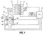
- FIG. 1 is a block diagram of a system to which this embodiment is applied.
- FIG. 2 is a sectional view of the vicinity of holding parts for a DOC and a DPF.
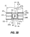
- FIGs. 3A-3C illustrate a first embodiment, FIG. 3A being a top view of a cap, FIG. 3B being a side view of the cap seen from a sensor attachment portion side, and FIG. 3C being a sectional view along IIIb-IIIb in FIG. 3B.
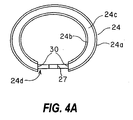
- FIGs. 4A-4C illustrate a partially modified example of the first embodiment, FIG. 4A being a top view of the cap, FIG. 4B being a side view of the cap seen from the sensor attachment portion side, and FIG. 4C being a sectional view along IVb-IVb in FIG. 4B.
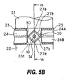
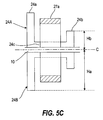
- FIGs. 5A-5C illustrate a partially modified example of the first embodiment, FIG. 5A being a top view of the cap, FIG. 5B being a side view of the cap seen from the sensor attachment portion side, and FIG. 5C being a sectional view along Vb-Vb in FIG. 5B.
- FIGs. 6A-6C illustrate a second embodiment, FIG. 6A being a top view of a cap, FIG. 6B being a side view of the cap seen from a sensor attachment portion side, and FIG. 6C being a sectional view along VIb-VIb in FIG. 6B.
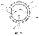
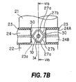
- FIGs. 7A-7C illustrate a partially modified example of the second embodiment, FIG. 7A being a top view of the cap, FIG. 7B being a side view of the cap seen from the sensor attachment portion side, and FIG. 7C being a sectional view along VIIb-VIIb in FIG. 7B.
- FIGs. 8A-8C illustrate a partially modified example of the second embodiment, FIG. 8A being a top view of the cap, FIG. 8B being a side view of the cap seen from the sensor attachment portion side, and FIG. 8C being a sectional view along VIIIb-VIIIb in FIG. 8B.
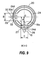
- FIG. 9 is a view illustrating the relationship between a bridge and a bridge in the second embodiment.
- FIG. 10A is a schematic diagram showing a state in which the cap is rotated within a case.
- FIG. 10B is a schematic diagram showing a state in which the cap is rotated within a case.
- FIG. 1 is a block diagram showing a case in which an exhaust gas purification device according to this invention is applied to a diesel engine having a turbo supercharger.
- An engine 1 is a diesel engine comprising a so-called common rail fuel injection device 4.
- a turbo supercharger 9 and an exhaust gas purification device 6 are provided in an exhaust passage 8 which is connected to an exhaust manifold 3 of the engine 1.
- An intake throttle and a compressor (not shown) of the turbo supercharger 9 are provided in an intake passage 7 which is connected to an upstream side of an intake manifold 2 of the engine 1.
- a control unit (ECU) 5 reads detection values APO, ENG, REV from a temperature sensor 10, an accelerator depression amount sensor and engine rotation speed sensor not shown in the drawing, and so on, and controls a fuel injection amount, injection timing, and so on of the engine 1 on the basis of these detection values.
- a DOC 21 (oxidation catalyst, first catalyst carrier) and a DPF 22 (diesel particulate filter, second catalyst carrier) are housed within a single case 20.
- a cap 24 which holds the DOC 21 and DPF 22, the temperature sensor 10 which detects a temperature upstream of the DPF 22, a pressure sensor 30 which detects a pressure upstream of the DPF 22, a temperature sensor 31 which detects a temperature downstream of the DPF 22, and a pressure sensor 32 which detects a pressure downstream of the DPF 22, are attached to the case 20.
- FIG. 2 is a sectional view of the vicinity of a downstream side end portion of the DOC 21 and an upstream side end portion of the DPF 22.
- the annular cap 24 holds the DOC 21 and DPF 22 via a washer 23.
- a filler 25 is filled between an outer periphery of the DOC 21 and DPF 22 and an inner peripheral wall of the case 20.
- the exhaust gas temperature at the inlet to the DPF 22 is detected by the temperature sensor 10.
- the washer 23 is an elastic body constituted by wire mesh or the like which is fitted into a gap between an outside edge portion 24a and an inside edge portion 24b of the cap 24. After being fitted into the gap, the washer 23 may be joined to the cap 24 by welding, adhesion, or another method.
- the filler 25 is constituted by matted incombustible fibers.
- the filler 25 functions mainly to seal the gap between the inner peripheral surface of the case 20 and the outer peripheral surface of the DOC 21 and DPF 22 to ensure that no exhaust gas flows through this part.
- the DOC 21 and DPF 22 are press-fitted into the case 20 with the filler 25 wound around them.
- the DOC 21 and DPF 22 are housed within the case 20 on the upstream side and downstream side respectively.
- the cap 24 and washer 23 which have a substantially identical diameter to the DOC 21 and DPF 22, are interposed between the two catalyst carriers, the two catalyst carriers do not come into contact with each other.
- a sensor attachment portion 26 is provided in the case 20 in a position corresponding to a bridge 27 of the cap 24, to be described below. As shown in FIG. 2, when the temperature sensor 10 is inserted, a sensing part on the tip end of the temperature sensor 10 is positioned on the inner peripheral side of the cap 24 and between the DOC 21 and DPF 22.
- a holder (cap 24A) for the DOC 21 and a holder (cap 24B) for the DPF 22 are integrated such that both the DOC 21 and the DPF 22 are held by a single holder. Therefore, the DOC 21 and DPF 22 can be housed in series within a narrower space than that of the prior art, and a space can be secured for the sensing that is performed by the temperature sensor 10 and so on. Moreover, the number of components interposed between the DOC 21 and DPF 22 can be reduced, enabling a reduction in the number of steps required to assemble the exhaust gas purification device 6.
- the temperature sensor 10 can be provided between the DOC 21 and DPF 22, or in other words at the inlet part of the DPF 22, appropriate regeneration control can be performed by detecting the temperature of the exhaust gas flowing into the DPF 22 even when the temperature increase produced by the oxidation reaction decreases due to deterioration of the DOC 21 or the like.
- cap attachment portion Referring to FIGs. 2 and 3A-3C, the structure of the cap attachment portion will be described in further detail.
- FIG. 3A is a top view of the cap 24, FIG. 3B is a side view of the cap 24 seen from the sensor attachment portion 26 side, and FIG. 3C is a sectional view along IIIb-IIIb in FIG. 3B.
- the cap 24 has a substantially identical diameter to the DOC 21 and DPF 22, and as shown in FIG. 2, is constituted by the outside edge (outside edge portion hereafter) 24a, which serves as an outer wall portion on the outer peripheral side, the inside edge (inside edge portion hereafter) 24b, which serves as an inner wall portion on the inner peripheral side, and a base portion 24c, which serves as a connection portion connecting the substantially central parts of the outside edge portion 24a and inside edge portion 24b.
- the cap 24 has a substantially H-shaped sectional form in which the outside edge portion 24a and inside edge portion 24b extend substantially parallel to each other from the outer peripheral edge and inner peripheral edge of the base portion 24c, respectively, toward both the upstream side and downstream side.
- the cap 24 has a substantially C-shaped annular form comprising a notch portion 24d that is formed by cutting away a part of the outside edge portion 24a and inside edge portion 24b.
- the notch portion 24d is joined by the base portion 24c (bridge 27 hereafter), which is not cut away.
- the outside edge portion 24a is positioned on the outside of the DOC 21 and DPF 22.
- the cap 24 described above By positioning the cap 24 described above such that the bridge 27 is in alignment with the sensor attachment portion 26 of the case 20, a space required for sensing the temperature can be secured between the DOC 21 and DPF 22. Furthermore, by providing the bridge 27, the strength of the cap 24 can be improved in comparison with a substantially C-shaped form in which notch portions are merely provided for mounting the temperature sensor 10.
- the cap 24 is constituted by the DOC cap 24A which holds the DOC 21 and the DPF cap 24B which holds the DPF 22, and both of the caps 24A, 24B have a substantially U-shaped cross-section constituted by the outside edge portion 24a, inside edge portion 24b, and base portion 24c. After aligning the notch portions 24d, the base portions 24c of the two caps 24A, 24B are welded together to obtain the substantially H-shaped cross-section shown in FIG. 3C.
- a height Ha from a joint line C of the cap 24A and the cap 24B to the end portion of the outside edge portion 24a is greater than a height Hb from the joint line C to the end portion of the inside edge portion 24b.
- the bridge 27 is constituted by wall surfaces 27b (first wall portions) which are substantially perpendicular to the base portion 24c, and upper surfaces 27a (second wall portions) which are substantially parallel to the base portion 24c, thereby forming a substantially square opening 34.
- the upper surface 27a is provided in a higher position than the upper end of the inside edge portion 24b.
- the substantially square shaped part formed by the bridge 27 is provided in a position corresponding to the sensor attachment portion 26, and the sensing part of the temperature sensor 10 penetrates this part.
- the bridge upper surface 27a of the bridge 27 acts as a stopper when the washer 23 contracts due to temporal deterioration, exhaust pressure, and so on, when the DOC 21 or DPF 22 shifts position, and in other such situations. Hence, damage to the DOC 21 or DPF 22 caused by contact with the inside edge portion 27b can be prevented. Moreover, space is secured between the DOC 21 and DPF 22 and the temperature sensor 10, and therefore the temperature sensor 10 can perform accurate sensing.
- the wall surface 27b of the bridge 27 is formed substantially perpendicular to the base portion 24c, and therefore an end 30 of the notch portion 24d in the cap 24 is blocked by the wall surface 27b.
- an end surface 23a of the washer 23 near the end 30 of the notch portion 24d is unlikely to be exposed to the exhaust gas flowing through the interior of the case 20, and as a result, it is possible to prevent corrosion and scattering of the washer 23 by the exhaust gas.
- the upper surface 27a and wall surface 27b of the bridge 27 are formed by bending a part of the annular base portion 24c, but the base portion 24c may be molded into a C shape, and a notch portion in the base portion 24c may be joined by a bridge 27 which is formed separately.
- the bridge 27 is not limited to a single location, and may be provided in a plurality when a pressure sensor or the like is provided in addition to the temperature sensor 10, as described below.
- the cap 24 is formed from the DOC cap 24A and DPF cap 24B, which are formed separately and then integrated by welding, but the cap 24 may be formed as a single body from the beginning.
- the DOC 21 is provided on the upstream side
- the DPF 22 is provided on the downstream side
- the temperature sensor 10 is provided between the DOC 21 and DPF 22.
- the catalyst carriers are not limited to the DOC 21 and DPF 22, and for example, the upstream side catalyst carrier may be an NOx catalyst, and the downstream side catalyst carrier may be a three way catalyst.
- the sensor 10 is not limited to a temperature sensor, and may be a pressure sensor, for example.
- the bridge 27 is not limited to the shape described above, and may take a form such as those shown in FIGs. 4A-4C and FIGs. 5A-5C.
- FIGs. 4A-4C show the upper face, side face, and cross-section of the cap 24, similarly to FIGs. 3A-3C.
- the bridge 27 takes a substantially hexagonal shape formed by the wall surfaces 27b, which extend from the base portion 24c toward the DOC 21 side and DPF 22 side so as to recede from the respective ends 30, and the upper surfaces 27a, which connect the upper ends and the lower ends of the wall surfaces 27b to each other, respectively.
- the upper surface 27a is positioned higher than the upper end of the inside edge portion 24b.
- FIGs. 5A-5C also show the upper face, side face, and cross-section of the cap 24, similarly to FIGs. 3A-3C.
- the bridge 27 takes a substantially square shape in which the wall surfaces 27b extend from the base portion 24c toward the DOC 21 side and DPF 22 side so as to recede from the respective ends 30, and the tip end portions of the wall surfaces 27b meet in the substantial center of the notch portion 24d.
- a connection portion 27e between the wall surfaces 27b is positioned higher than the upper end of the inside edge portion 24b.
- the exhaust gas purification device 6 comprises the DOC 21, the DPF 22, the case 20 housing the DOC 21 and DPF 22 in series in the flow direction of the exhaust gas, the cap 24 interposed between the DOC 21 and DPF 22, which holds the DOC 21 and DPF 22 via the washer 23, the notch portion provided in the cap 24, the temperature sensor 10 which detects the state of the exhaust gas flowing through the interior of the case 20, and the sensor attachment portion 26 provided in the case 20.
- the sensor attachment portion 26 is provided in a position corresponding to the notch portion in the cap 24 when the cap 24 is housed in the case 20, and therefore the DOC 21 and DPF 22 can be accommodated in the single case 20 in a compact manner, and the temperature of the exhaust gas at the inlet part of the DPF 22 can be detected.
- the case 20 housing the DOC 21 and DPF 22 is preferably disposed in a location where the exhaust gas temperature is high, for example directly below the exhaust manifold 3 of the engine 1 or directly below the turbo supercharger 9 in the case of a vehicle installed with the turbo supercharger 9.
- the exhaust gas purification device 6 has a compact constitution, and can therefore be disposed in the small space directly beneath the turbo supercharger 9.
- the number of components can be reduced, and the number and steps required to assemble the exhaust gas purification device 6 can be reduced.
- a carrier holder is constituted by the substantially C-shaped cap 24 having the notch portion 24d in a part of the circumference thereof and the bridge 27 which bridges the notch portion 24d in the cap 24, and the bridge 27 forms a space for the sensor 10.
- the carrier holder is stronger than a C-shaped ring member which is merely provided with a notch portion in a part of the circumference thereof.
- the bridge 27 is constituted by the wall surfaces 27b, which extend from the base portion 24c in the upstream and downstream directions of the exhaust gas flow so as to block the two ends of the notch portion 24d, and the upper surfaces 27a which connect the upstream side end portions and the downstream side end portions of the wall surfaces 27b to each other, respectively.
- the bridge 27 forms a tubular part which connects the inner peripheral side and outer peripheral side of the cap 24, enabling a space required for the sensing performed by the sensor 10 to be secured.
- the distance from the base portion 24c to the upper surface 27a is longer than the distance from the base portion 24c to the end portion of the inside edge portion 24b, and therefore the upper surface 27a acts as a stopper when the DOC 21 or DPF 22 shifts position due to deterioration of the washer 23, exhaust pressure, and so on. Therefore, a space required for the sensing performed by the sensor 10 can be secured, and damage to the DOC 21 and DPF 22 caused by interference with the inside edge portion 24b can be prevented.
- the second embodiment differs from the first embodiment in that two sensor attachment portions 26, 28 are provided in the cap 24, and the temperature sensor 10 and pressure sensor 30 are attached to the respective sensor attachment portions 26, 28.
- the overall constitution of the device is identical to that shown in FIG. 1.
- the peripheral structures of the attachment portions for the temperature sensor 10 and pressure sensor 30 are substantially identical to the structures shown in FIG. 2 except that in the peripheral structure of the attachment portion 28 for the pressure sensor 30, a sensing part 30a on the tip end of the pressure sensor 30 does not penetrate a bridge 33.
- FIG. 6A is a top view of the cap 24 according to the second embodiment
- FIG. 6B is a side view of the cap 24 seen from the sensor attachment portion 26 side
- FIG. 6C is a sectional view along VIb-VIb in FIG. 6B.
- a side view of the cap 24 seen from the sensor attachment portion 28 side and the sectional view thereof are similar to FIGs. 6B and 6C.
- the cap 24 has a substantially identical diameter to the DOC 21 and DPF 22, and as shown in FIG. 2, is constituted by the outside edge (outside edge portion hereafter) 24a, which serves as an outer wall portion on the outer peripheral side, the inside edge (inside edge portion hereafter) 24b, which serves as an inner wall portion on the inner peripheral side, and the base portion 24c, which serves as a connection portion connecting the substantially central parts of the outside edge portion 24a and inside edge portion 24b.
- the cap 24 has a substantially H-shaped sectional form in which the outside edge portion 24a and inside edge portion 24b extend substantially parallel to each other from the outer peripheral edge and inner peripheral edge of the base portion 24c, respectively, toward both the upstream side and downstream side.
- the notch portions 24d are provided in two locations in the outside edge portion 24a and inside edge portion 24b when the cap 24 is seen from above, and the notch portions 24d are joined by the base portion 24c (bridge 27, bridge 33 hereafter), which is not cut away.
- the outside edge portion 24a is positioned on the outside of the DOC 21 and DPF 22.
- the cap 24 described above By disposing the cap 24 described above such that the bridges 27, 33 are in alignment with the respective sensor attachment portions 26, 28 of the case 20, the spaces required for the sensing performed by the temperature sensor 10 and pressure sensor 30 can be secured between the DOC 21 and DPF 22. Furthermore, by providing the bridges 27, 33, the cap 24 having the notch portions 24d in two locations can be formed as an integral member.
- the cap 24 is constituted by the DOC cap 24A which holds the DOC 21 and the DPF cap 24B which holds the DPF 22, and both of the caps 24A, 24B have a substantially U-shaped cross-section constituted by the outside edge portion 24a, inside edge portion 24b, and base portion 24c. After aligning the notch portions 24d, the base portions 24c of the two caps 24A, 24B are welded together to obtain the substantially H-shaped cross-section shown in FIG. 6C.
- the height Ha from the joint line C of the cap 24B to the end portion of the outside edge portion 24a is greater than the height Hb from the joint line C to the end portion of the inside edge portion 24b.
- the bridge 27 is constituted by the wall surfaces 27b (first wall portions), which are substantially perpendicular to the base portion 24c, and the upper surfaces 27a (second wall portions), which are substantially parallel to the base portion 24c, thereby forming the substantially square opening 34.
- the upper surface 27a is provided in a higher position than the upper end of the inside edge portion 24b.
- the substantially square shaped part formed by the bridge 27 is provided in a position corresponding to the sensor attachment portion 26, and the sensing part of the temperature sensor 10 penetrates this part.
- the bridge upper surface 27a of the bridge 27 acts as a stopper when the washer 23 contracts due to temporal deterioration, exhaust pressure, and so on, when the DOC 21 or DPF 22 shifts position, and in other such situations. Hence, damage to the DOC 21 or DPF 22 caused by contact with the inside edge portion 27b can be prevented. Moreover, space is secured between the DOC 21 and DPF 22 and the temperature sensor 10, and therefore the temperature sensor 10 can perform accurate sensing.
- the wall surface 27b of the bridge 27 is formed substantially perpendicular to the base portion 24c, and therefore the end 30 of the notch portion 24d in the cap 24 is blocked by the wall surface 27b.
- the end surface 23a of the washer 23 near the end 30 of the notch portion 24d is unlikely to be exposed to the exhaust gas flowing through the interior of the case 20, and as a result, it is possible to prevent corrosion and scattering of the washer 23 by the exhaust gas.
- the upper surface 27a and wall surface 27b of the bridge 27 are formed by bending a part of the annular base portion 24c, but the base portion 24c may be molded into a C shape, and a notch portion in the base portion 24c may be joined by a bridge 27 which is formed separately.
- the bridge 33 has a similar structure to the bridge 27, and hence description thereof has been omitted.
- the bridges 27, 33 are not limited to the shape described above, and may take a form such as those shown in FIGs. 7A-7C and FIGs. 8A-8C. It should be noted that since the bridge 27 and the bridge 33 are structured similarly, only the bridge 27 will be described.
- FIGs. 7A-7C show the upper face, side face, and cross-section of the cap 24, similarly to FIGs. 6A-6C.
- the bridge 27 takes a substantially hexagonal shape formed by the wall surfaces 27b, which extend from the base portion 24c toward the DOC 21 side and DPF 22 side so as to recede from the respective ends 30, and the upper surfaces 27a, which connect the upper ends and the lower ends of the wall surfaces 27b to each other, respectively.
- the upper surface 27a is positioned higher than the upper end of the inside edge portion 24b.
- FIGs. 8A-8C also show the upper face, side face, and cross-section of the cap 24, similarly to FIGs. 6A-6C.
- the bridge 27 takes a substantially square shape in which the wall surfaces 27b extend from the base portion 24c toward the DOC 21 side and DPF 22 side so as to recede from the respective ends 30, and the tip end portions of the wall surfaces 27b meet in the substantial center of the notch portion 24d.
- the connection portion 27e between the wall surfaces 27b is positioned higher than the upper end of the inside edge portion 24b.
- FIG. 9 is a schematic diagram seen from the upper face of the case 20, and FIGs. 10A, 10B are views showing states in which the cap 24 is rotated in the interior of the case 20.
- the temperature sensor 10 and pressure sensor 30 are attached to the case 20 such that the respective tip ends thereof are oriented in the axial center direction of the case 20.
- the sensing part 10a of the temperature sensor 10 penetrates the central portion of the bridge 27 in the circumferential direction, while the pressure sensor 30 is attached in a position facing the central portion of the bridge 33 in the circumferential direction.
- the sensing part 30a of the pressure sensor 30 is shorter than the sensing part 10a of the temperature sensor 10, and therefore the sensing part 30a does not penetrate the opening in the bridge 33.
- a length B of the bridge 33 in the circumferential direction is greater than a length C of the bridge 27 in the circumferential direction.
- the cap 24 may rotate in the circumferential direction due to deterioration of the washer 23, filler 25, and so on, or vibration and the like generated during traveling.
- the angle of this rotation reaches a maximum when the wall surface 27b of the bridge 27 interferes with the sensing part 10a of the temperature sensor 10.
- the sensing part 30a of the pressure sensor 30 faces the outside edge portion 24a when the cap 24 rotates in the clockwise direction of FIG. 9 to the aforesaid maximum rotation angle, for example, and hence the required sensing space cannot be secured.
- the circumferential direction length B of the bridge 33 is greater than the circumferential direction length C of the bridge 27, and therefore the pressure sensor 30 is exposed through the opening in the bridge 33 even at the maximum rotation angle, as shown in FIG. 10B. Hence, the required sensing space can be secured. This relationship is established likewise when the rotation direction of the cap 24 is opposite to that shown in FIGs. 10A, 10B.
- the space required for the sensing performed by the temperature sensor 10 and pressure sensor 30 is secured even when the cap 24 rotates within the case 20.
- the precision with which the amount of soot in the DPF and so on are estimated on the basis of the detection values of the sensors 10, 30 is not reduced by rotation of the cap 24, and therefore deterioration of the DPF, decreased fuel economy, and similar problems can be prevented.
- the angle formed by the temperature sensor 10 and pressure sensor 30 is set at substantially ninety degrees, but this invention is not limited thereto.
- the second embodiment exhibits the following actions and effects.
- the carrier holder is constituted by the cap 24 having notch portions 24d in two circumferential locations when seen from the exhaust gas flow direction, and the bridges 27, 33 bridging the notch portions 24d in the cap 24.
- a space for the temperature sensor 10 can be formed by the bridge 27, and a space for the pressure sensor 30 can be formed by the bridge 33.
- the circumferential direction length of the bridge 27 is shorter than the circumferential direction length of the bridge 33, and therefore, even when the cap 24 rotates in the circumferential direction to a point where it interferes with the sensing part 10a of the temperature sensor 10 due to temporal deterioration, vibration generated when the vehicle is in motion, or a similar cause, the sensing part 30a of the pressure sensor 30 faces the opening in the bridge 33, and hence both the temperature sensor 10 and the pressure sensor 30 are able to perform sensing reliably.
Landscapes
- Engineering & Computer Science (AREA)
- Chemical & Material Sciences (AREA)
- Combustion & Propulsion (AREA)
- Mechanical Engineering (AREA)
- General Engineering & Computer Science (AREA)
- Chemical Kinetics & Catalysis (AREA)
- Health & Medical Sciences (AREA)
- Toxicology (AREA)
- Analytical Chemistry (AREA)
- Exhaust Gas After Treatment (AREA)
- Exhaust Gas Treatment By Means Of Catalyst (AREA)
Abstract
Description
- This invention relates to a technique for disposing a plurality of catalyst carriers in an exhaust gas purification device, serially in an exhaust gas flow direction.
- A diesel particulate filter (DPF hereafter) is known as a device for removing PM discharged from a diesel engine. A DPF is a filter which traps particulate matter (PM) contained in exhaust gas, and is required to perform so-called regeneration processing to remove the trapped PM through oxidation when the trapped PM amount reaches a fixed amount. A method of heating the DPF using a heating device such as a heater when the trapped PM amount reaches a predetermined value is known as a method of performing this regeneration processing, but with this method, a regeneration device must be provided, leading to an increase in cost.
- In a known method for solving this problem, an oxidation catalyst (DOC hereafter) is provided in an exhaust passage on the upstream side of the DPF for oxidizing NO contained in the exhaust gas to generate NO2. The DPF is then regenerated by oxidizing the PM trapped the filter continuously using the heat of the exhaust gas and the NO2. In an exhaust gas purification device disclosed in JP2001-280118A, regeneration is performed using this method. The DOC and DPF are housed in a single case, and when the PM amount trapped in the DPF exceeds a predetermined amount, the exhaust gas temperature is raised through post-injection of the fuel and so on in order to burn the trapped PM.
- When performing regeneration processing, it is important to manage the temperature of the exhaust gas that flows into the DPF to ensure that the PM is burned while preventing deterioration of the DPF.
- In a known method of detecting the temperature of the exhaust gas flowing into the DPF, a temperature sensor is provided in the vicinity of a DOC inlet, and the exhaust gas temperature after passing through the DOC, or in other words the exhaust gas temperature at the inlet to the DPF, is estimated from the temperature detected by the temperature sensor and a preset temperature increase produced by the oxidation reaction in the DOC. With this method, however, a difference occurs between the preset temperature increase and actual temperature increase due to deterioration of the DOC or the like, and in such cases the inlet temperature of the DPF cannot be estimated accurately.
- Hence, a temperature sensor for performing temperature management is preferably provided in the vicinity of the DPF inlet. For similar reasons, a pressure sensor for estimating the trapped PM amount is preferably provided at the inlet part of the DPF.
- Furthermore, when the DOC and DPF are housed in a single case and a sensor is disposed in the vicinity of the DPF inlet, the position of the DOC or DPF may shift due to irregularities during assembly or exhaust pressure. As a result, the clearance between the sensor and the DOC or DPF may be narrowed, or interference may occur between the two components, leading to a deterioration in the detection precision. If structures for holding the DOC, DPF, and sensor individually are provided within the case to solve this problem, the case increases in size, leading to restrictions on the location in which the case can be disposed.
- JP2001-280118A provides no detailed description regarding the internal structure of the case or the manner in which the DOC and DPF are held, and also discloses that the temperature sensor is disposed on the upstream side of the case.
- It is therefore an object of this invention to make an exhaust gas purification device more compact by housing a plurality of catalyst carriers in a single case, and attaching sensors for detecting exhaust gas temperature and so on to an inlet part of the downstream side catalyst.
- In order to achieve above-mentioned object, this invention provides an exhaust gas purification device comprising: first and second catalyst carriers interposed in an exhaust passage of an engine, which purify an exhaust gas; a case provided in the exhaust passage, which houses the first and second catalyst carriers in series in an exhaust gas flow direction; an annular carrier holder interposed between the first and second catalyst carriers, which holds the first and second catalyst carriers via a buffering member and has a first opening which connects an inner peripheral side and an outer peripheral side; a first sensor which detects a state of the exhaust gas flowing through the interior of the case; and a first sensor attachment portion provided in the case, which connects the interior and exterior of the case in an orientation that is substantially orthogonal to the exhaust gas flow direction. The first sensor attachment portion is provided in a position corresponding to the first opening when the carrier holder is housed in the case.
- The details as well as other features and advantages of this invention are set forth in the remainder of the specification and are shown in the accompanying drawings.
- FIG. 1 is a block diagram of a system to which this embodiment is applied.
- FIG. 2 is a sectional view of the vicinity of holding parts for a DOC and a DPF.
- FIGs. 3A-3C illustrate a first embodiment, FIG. 3A being a top view of a cap, FIG. 3B being a side view of the cap seen from a sensor attachment portion side, and FIG. 3C being a sectional view along IIIb-IIIb in FIG. 3B.
- FIGs. 4A-4C illustrate a partially modified example of the first embodiment, FIG. 4A being a top view of the cap, FIG. 4B being a side view of the cap seen from the sensor attachment portion side, and FIG. 4C being a sectional view along IVb-IVb in FIG. 4B.
- FIGs. 5A-5C illustrate a partially modified example of the first embodiment, FIG. 5A being a top view of the cap, FIG. 5B being a side view of the cap seen from the sensor attachment portion side, and FIG. 5C being a sectional view along Vb-Vb in FIG. 5B.
- FIGs. 6A-6C illustrate a second embodiment, FIG. 6A being a top view of a cap, FIG. 6B being a side view of the cap seen from a sensor attachment portion side, and FIG. 6C being a sectional view along VIb-VIb in FIG. 6B.
- FIGs. 7A-7C illustrate a partially modified example of the second embodiment, FIG. 7A being a top view of the cap, FIG. 7B being a side view of the cap seen from the sensor attachment portion side, and FIG. 7C being a sectional view along VIIb-VIIb in FIG. 7B.
- FIGs. 8A-8C illustrate a partially modified example of the second embodiment, FIG. 8A being a top view of the cap, FIG. 8B being a side view of the cap seen from the sensor attachment portion side, and FIG. 8C being a sectional view along VIIIb-VIIIb in FIG. 8B.
- FIG. 9 is a view illustrating the relationship between a bridge and a bridge in the second embodiment.
- FIG. 10A is a schematic diagram showing a state in which the cap is rotated within a case.
- FIG. 10B is a schematic diagram showing a state in which the cap is rotated within a case.
- Embodiments of this invention will now be described with reference to the attached drawings.
- First Embodiment
- FIG. 1 is a block diagram showing a case in which an exhaust gas purification device according to this invention is applied to a diesel engine having a turbo supercharger.
- An engine 1 is a diesel engine comprising a so-called common rail
fuel injection device 4. Aturbo supercharger 9 and an exhaustgas purification device 6 are provided in an exhaust passage 8 which is connected to anexhaust manifold 3 of the engine 1. An intake throttle and a compressor (not shown) of theturbo supercharger 9 are provided in anintake passage 7 which is connected to an upstream side of anintake manifold 2 of the engine 1. - A control unit (ECU) 5 reads detection values APO, ENG, REV from a
temperature sensor 10, an accelerator depression amount sensor and engine rotation speed sensor not shown in the drawing, and so on, and controls a fuel injection amount, injection timing, and so on of the engine 1 on the basis of these detection values. - In the exhaust
gas purification device 6, a DOC 21 (oxidation catalyst, first catalyst carrier) and a DPF 22 (diesel particulate filter, second catalyst carrier) are housed within asingle case 20. Acap 24 which holds theDOC 21 andDPF 22, thetemperature sensor 10 which detects a temperature upstream of theDPF 22, apressure sensor 30 which detects a pressure upstream of theDPF 22, atemperature sensor 31 which detects a temperature downstream of theDPF 22, and apressure sensor 32 which detects a pressure downstream of theDPF 22, are attached to thecase 20. - Referring to FIG. 2, the exhaust
gas purification device 6 will now be described in more detail. FIG. 2 is a sectional view of the vicinity of a downstream side end portion of theDOC 21 and an upstream side end portion of theDPF 22. Theannular cap 24 holds theDOC 21 andDPF 22 via awasher 23. Afiller 25 is filled between an outer periphery of theDOC 21 andDPF 22 and an inner peripheral wall of thecase 20. The exhaust gas temperature at the inlet to theDPF 22 is detected by thetemperature sensor 10. - The
washer 23 is an elastic body constituted by wire mesh or the like which is fitted into a gap between anoutside edge portion 24a and aninside edge portion 24b of thecap 24. After being fitted into the gap, thewasher 23 may be joined to thecap 24 by welding, adhesion, or another method. - The
filler 25 is constituted by matted incombustible fibers. Thefiller 25 functions mainly to seal the gap between the inner peripheral surface of thecase 20 and the outer peripheral surface of theDOC 21 andDPF 22 to ensure that no exhaust gas flows through this part. TheDOC 21 andDPF 22 are press-fitted into thecase 20 with thefiller 25 wound around them. - Thus, the
DOC 21 andDPF 22 are housed within thecase 20 on the upstream side and downstream side respectively. However, since thecap 24 andwasher 23, which have a substantially identical diameter to theDOC 21 andDPF 22, are interposed between the two catalyst carriers, the two catalyst carriers do not come into contact with each other. - A
sensor attachment portion 26 is provided in thecase 20 in a position corresponding to abridge 27 of thecap 24, to be described below. As shown in FIG. 2, when thetemperature sensor 10 is inserted, a sensing part on the tip end of thetemperature sensor 10 is positioned on the inner peripheral side of thecap 24 and between theDOC 21 andDPF 22. - As described above, in the exhaust gas purification device according to this invention, a holder (
cap 24A) for theDOC 21 and a holder (cap 24B) for theDPF 22 are integrated such that both theDOC 21 and theDPF 22 are held by a single holder. Therefore, theDOC 21 andDPF 22 can be housed in series within a narrower space than that of the prior art, and a space can be secured for the sensing that is performed by thetemperature sensor 10 and so on. Moreover, the number of components interposed between theDOC 21 andDPF 22 can be reduced, enabling a reduction in the number of steps required to assemble the exhaustgas purification device 6. - Furthermore, there is no need to align the positions of both the
DOC 21 holder and theDPF 22 holder with thesensor attachment portion 26. Moreover, inaccurate sensing due to a reduction in the clearance between, or interference between, the sensing part of thetemperature sensor 10 and theDOC 21 orDPF 22, caused by shifting of the upper and lower holders or the like following assembly of the exhaustgas purification device 6, can be prevented. - Further, since the
temperature sensor 10 can be provided between theDOC 21 andDPF 22, or in other words at the inlet part of theDPF 22, appropriate regeneration control can be performed by detecting the temperature of the exhaust gas flowing into theDPF 22 even when the temperature increase produced by the oxidation reaction decreases due to deterioration of theDOC 21 or the like. - Referring to FIGs. 2 and 3A-3C, the structure of the cap attachment portion will be described in further detail.
- FIG. 3A is a top view of the
cap 24, FIG. 3B is a side view of thecap 24 seen from thesensor attachment portion 26 side, and FIG. 3C is a sectional view along IIIb-IIIb in FIG. 3B. - The
cap 24 has a substantially identical diameter to theDOC 21 andDPF 22, and as shown in FIG. 2, is constituted by the outside edge (outside edge portion hereafter) 24a, which serves as an outer wall portion on the outer peripheral side, the inside edge (inside edge portion hereafter) 24b, which serves as an inner wall portion on the inner peripheral side, and abase portion 24c, which serves as a connection portion connecting the substantially central parts of theoutside edge portion 24a andinside edge portion 24b. Thecap 24 has a substantially H-shaped sectional form in which theoutside edge portion 24a andinside edge portion 24b extend substantially parallel to each other from the outer peripheral edge and inner peripheral edge of thebase portion 24c, respectively, toward both the upstream side and downstream side. - When seen from above, the
cap 24 has a substantially C-shaped annular form comprising anotch portion 24d that is formed by cutting away a part of theoutside edge portion 24a andinside edge portion 24b. Thenotch portion 24d is joined by thebase portion 24c (bridge 27 hereafter), which is not cut away. Theoutside edge portion 24a is positioned on the outside of theDOC 21 andDPF 22. - By positioning the
cap 24 described above such that thebridge 27 is in alignment with thesensor attachment portion 26 of thecase 20, a space required for sensing the temperature can be secured between theDOC 21 andDPF 22. Furthermore, by providing thebridge 27, the strength of thecap 24 can be improved in comparison with a substantially C-shaped form in which notch portions are merely provided for mounting thetemperature sensor 10. - It should be noted that the
cap 24 is constituted by theDOC cap 24A which holds theDOC 21 and theDPF cap 24B which holds theDPF 22, and both of thecaps outside edge portion 24a,inside edge portion 24b, andbase portion 24c. After aligning thenotch portions 24d, thebase portions 24c of the twocaps - Further, as shown in FIG. 3C, a height Ha from a joint line C of the
cap 24A and thecap 24B to the end portion of theoutside edge portion 24a is greater than a height Hb from the joint line C to the end portion of theinside edge portion 24b. - As shown in FIG. 3B, the
bridge 27 is constituted bywall surfaces 27b (first wall portions) which are substantially perpendicular to thebase portion 24c, andupper surfaces 27a (second wall portions) which are substantially parallel to thebase portion 24c, thereby forming a substantiallysquare opening 34. As shown in FIG. 3C, theupper surface 27a is provided in a higher position than the upper end of theinside edge portion 24b. The substantially square shaped part formed by thebridge 27 is provided in a position corresponding to thesensor attachment portion 26, and the sensing part of thetemperature sensor 10 penetrates this part. - By forming the
upper surface 27a of thebridge 27 higher than the upper end of theinside edge portion 24b in this manner, the bridgeupper surface 27a acts as a stopper when thewasher 23 contracts due to temporal deterioration, exhaust pressure, and so on, when theDOC 21 orDPF 22 shifts position, and in other such situations. Hence, damage to theDOC 21 orDPF 22 caused by contact with theinside edge portion 27b can be prevented. Moreover, space is secured between theDOC 21 andDPF 22 and thetemperature sensor 10, and therefore thetemperature sensor 10 can perform accurate sensing. - Further, the
wall surface 27b of thebridge 27 is formed substantially perpendicular to thebase portion 24c, and therefore anend 30 of thenotch portion 24d in thecap 24 is blocked by thewall surface 27b. Hence, anend surface 23a of thewasher 23 near theend 30 of thenotch portion 24d is unlikely to be exposed to the exhaust gas flowing through the interior of thecase 20, and as a result, it is possible to prevent corrosion and scattering of thewasher 23 by the exhaust gas. - In this embodiment, the
upper surface 27a andwall surface 27b of thebridge 27 are formed by bending a part of theannular base portion 24c, but thebase portion 24c may be molded into a C shape, and a notch portion in thebase portion 24c may be joined by abridge 27 which is formed separately. - Furthermore, the
bridge 27 is not limited to a single location, and may be provided in a plurality when a pressure sensor or the like is provided in addition to thetemperature sensor 10, as described below. Moreover, in this embodiment thecap 24 is formed from theDOC cap 24A andDPF cap 24B, which are formed separately and then integrated by welding, but thecap 24 may be formed as a single body from the beginning. - Also in this embodiment, an example was described in which the
DOC 21 is provided on the upstream side, theDPF 22 is provided on the downstream side, and thetemperature sensor 10 is provided between theDOC 21 andDPF 22. However, the catalyst carriers are not limited to theDOC 21 andDPF 22, and for example, the upstream side catalyst carrier may be an NOx catalyst, and the downstream side catalyst carrier may be a three way catalyst. Furthermore, thesensor 10 is not limited to a temperature sensor, and may be a pressure sensor, for example. - The
bridge 27 is not limited to the shape described above, and may take a form such as those shown in FIGs. 4A-4C and FIGs. 5A-5C. - FIGs. 4A-4C show the upper face, side face, and cross-section of the
cap 24, similarly to FIGs. 3A-3C. In this example, as shown in FIG. 4B, thebridge 27 takes a substantially hexagonal shape formed by the wall surfaces 27b, which extend from thebase portion 24c toward theDOC 21 side andDPF 22 side so as to recede from the respective ends 30, and theupper surfaces 27a, which connect the upper ends and the lower ends of the wall surfaces 27b to each other, respectively. In this case also, theupper surface 27a is positioned higher than the upper end of theinside edge portion 24b. - FIGs. 5A-5C also show the upper face, side face, and cross-section of the
cap 24, similarly to FIGs. 3A-3C. In this example, as shown in FIG. 5B, thebridge 27 takes a substantially square shape in which the wall surfaces 27b extend from thebase portion 24c toward theDOC 21 side andDPF 22 side so as to recede from the respective ends 30, and the tip end portions of the wall surfaces 27b meet in the substantial center of thenotch portion 24d. In this case, aconnection portion 27e between the wall surfaces 27b is positioned higher than the upper end of theinside edge portion 24b. - The actions and effects of the first embodiment will now be summarized.
- The exhaust
gas purification device 6 comprises theDOC 21, theDPF 22, thecase 20 housing theDOC 21 andDPF 22 in series in the flow direction of the exhaust gas, thecap 24 interposed between theDOC 21 andDPF 22, which holds theDOC 21 andDPF 22 via thewasher 23, the notch portion provided in thecap 24, thetemperature sensor 10 which detects the state of the exhaust gas flowing through the interior of thecase 20, and thesensor attachment portion 26 provided in thecase 20. Thesensor attachment portion 26 is provided in a position corresponding to the notch portion in thecap 24 when thecap 24 is housed in thecase 20, and therefore theDOC 21 andDPF 22 can be accommodated in thesingle case 20 in a compact manner, and the temperature of the exhaust gas at the inlet part of theDPF 22 can be detected. - In consideration of advantageous conditions for regenerating the
DPF 22, thecase 20 housing theDOC 21 andDPF 22 is preferably disposed in a location where the exhaust gas temperature is high, for example directly below theexhaust manifold 3 of the engine 1 or directly below theturbo supercharger 9 in the case of a vehicle installed with theturbo supercharger 9. In an engine room, however, space is lacking directly below theturbo supercharger 9, and therefore in the past it has been difficult to dispose thesingle case 20 housing theDOC 21 andDPF 22 in such a location. According to this invention, on the other hand, the exhaustgas purification device 6 has a compact constitution, and can therefore be disposed in the small space directly beneath theturbo supercharger 9. - By integrating the
cap 24 andwasher 23, the number of components can be reduced, and the number and steps required to assemble the exhaustgas purification device 6 can be reduced. - A carrier holder is constituted by the substantially C-shaped
cap 24 having thenotch portion 24d in a part of the circumference thereof and thebridge 27 which bridges thenotch portion 24d in thecap 24, and thebridge 27 forms a space for thesensor 10. Thus the carrier holder is stronger than a C-shaped ring member which is merely provided with a notch portion in a part of the circumference thereof. - The
bridge 27 is constituted by the wall surfaces 27b, which extend from thebase portion 24c in the upstream and downstream directions of the exhaust gas flow so as to block the two ends of thenotch portion 24d, and theupper surfaces 27a which connect the upstream side end portions and the downstream side end portions of the wall surfaces 27b to each other, respectively. Thus thebridge 27 forms a tubular part which connects the inner peripheral side and outer peripheral side of thecap 24, enabling a space required for the sensing performed by thesensor 10 to be secured. - The distance from the
base portion 24c to theupper surface 27a is longer than the distance from thebase portion 24c to the end portion of theinside edge portion 24b, and therefore theupper surface 27a acts as a stopper when theDOC 21 orDPF 22 shifts position due to deterioration of thewasher 23, exhaust pressure, and so on. Therefore, a space required for the sensing performed by thesensor 10 can be secured, and damage to theDOC 21 andDPF 22 caused by interference with theinside edge portion 24b can be prevented. - Second Embodiment
- A second embodiment of this invention will now be described. The second embodiment differs from the first embodiment in that two
sensor attachment portions cap 24, and thetemperature sensor 10 andpressure sensor 30 are attached to the respectivesensor attachment portions temperature sensor 10 andpressure sensor 30 are substantially identical to the structures shown in FIG. 2 except that in the peripheral structure of theattachment portion 28 for thepressure sensor 30, a sensing part 30a on the tip end of thepressure sensor 30 does not penetrate abridge 33. - FIG. 6A is a top view of the
cap 24 according to the second embodiment, FIG. 6B is a side view of thecap 24 seen from thesensor attachment portion 26 side, and FIG. 6C is a sectional view along VIb-VIb in FIG. 6B. A side view of thecap 24 seen from thesensor attachment portion 28 side and the sectional view thereof are similar to FIGs. 6B and 6C. - The
cap 24 has a substantially identical diameter to theDOC 21 andDPF 22, and as shown in FIG. 2, is constituted by the outside edge (outside edge portion hereafter) 24a, which serves as an outer wall portion on the outer peripheral side, the inside edge (inside edge portion hereafter) 24b, which serves as an inner wall portion on the inner peripheral side, and thebase portion 24c, which serves as a connection portion connecting the substantially central parts of theoutside edge portion 24a andinside edge portion 24b. Thecap 24 has a substantially H-shaped sectional form in which theoutside edge portion 24a andinside edge portion 24b extend substantially parallel to each other from the outer peripheral edge and inner peripheral edge of thebase portion 24c, respectively, toward both the upstream side and downstream side. - The
notch portions 24d are provided in two locations in theoutside edge portion 24a andinside edge portion 24b when thecap 24 is seen from above, and thenotch portions 24d are joined by thebase portion 24c (bridge 27,bridge 33 hereafter), which is not cut away. Theoutside edge portion 24a is positioned on the outside of theDOC 21 andDPF 22. - By disposing the
cap 24 described above such that thebridges sensor attachment portions case 20, the spaces required for the sensing performed by thetemperature sensor 10 andpressure sensor 30 can be secured between theDOC 21 andDPF 22. Furthermore, by providing thebridges cap 24 having thenotch portions 24d in two locations can be formed as an integral member. - It should be noted that the
cap 24 is constituted by theDOC cap 24A which holds theDOC 21 and theDPF cap 24B which holds theDPF 22, and both of thecaps outside edge portion 24a,inside edge portion 24b, andbase portion 24c. After aligning thenotch portions 24d, thebase portions 24c of the twocaps - Further, as shown in FIG. 6C, the height Ha from the joint line C of the
cap 24B to the end portion of theoutside edge portion 24a is greater than the height Hb from the joint line C to the end portion of theinside edge portion 24b. - As shown in FIG. 6B, the
bridge 27 is constituted by the wall surfaces 27b (first wall portions), which are substantially perpendicular to thebase portion 24c, and theupper surfaces 27a (second wall portions), which are substantially parallel to thebase portion 24c, thereby forming the substantiallysquare opening 34. As shown in FIG. 6C, theupper surface 27a is provided in a higher position than the upper end of theinside edge portion 24b. The substantially square shaped part formed by thebridge 27 is provided in a position corresponding to thesensor attachment portion 26, and the sensing part of thetemperature sensor 10 penetrates this part. - By forming the
upper surface 27a of thebridge 27 higher than the upper end of theinside edge portion 24b in this manner, the bridgeupper surface 27a acts as a stopper when thewasher 23 contracts due to temporal deterioration, exhaust pressure, and so on, when theDOC 21 orDPF 22 shifts position, and in other such situations. Hence, damage to theDOC 21 orDPF 22 caused by contact with theinside edge portion 27b can be prevented. Moreover, space is secured between theDOC 21 andDPF 22 and thetemperature sensor 10, and therefore thetemperature sensor 10 can perform accurate sensing. - Further, the
wall surface 27b of thebridge 27 is formed substantially perpendicular to thebase portion 24c, and therefore theend 30 of thenotch portion 24d in thecap 24 is blocked by thewall surface 27b. Hence, theend surface 23a of thewasher 23 near theend 30 of thenotch portion 24d is unlikely to be exposed to the exhaust gas flowing through the interior of thecase 20, and as a result, it is possible to prevent corrosion and scattering of thewasher 23 by the exhaust gas. - In this embodiment, the
upper surface 27a andwall surface 27b of thebridge 27 are formed by bending a part of theannular base portion 24c, but thebase portion 24c may be molded into a C shape, and a notch portion in thebase portion 24c may be joined by abridge 27 which is formed separately. - The
bridge 33 has a similar structure to thebridge 27, and hence description thereof has been omitted. - The
bridges bridge 27 and thebridge 33 are structured similarly, only thebridge 27 will be described. - FIGs. 7A-7C show the upper face, side face, and cross-section of the
cap 24, similarly to FIGs. 6A-6C. In this example, as shown in FIG. 7B, thebridge 27 takes a substantially hexagonal shape formed by the wall surfaces 27b, which extend from thebase portion 24c toward theDOC 21 side andDPF 22 side so as to recede from the respective ends 30, and theupper surfaces 27a, which connect the upper ends and the lower ends of the wall surfaces 27b to each other, respectively. In this case also, theupper surface 27a is positioned higher than the upper end of theinside edge portion 24b. - FIGs. 8A-8C also show the upper face, side face, and cross-section of the
cap 24, similarly to FIGs. 6A-6C. In this example, as shown in FIG. 8B, thebridge 27 takes a substantially square shape in which the wall surfaces 27b extend from thebase portion 24c toward theDOC 21 side andDPF 22 side so as to recede from the respective ends 30, and the tip end portions of the wall surfaces 27b meet in the substantial center of thenotch portion 24d. In this case, theconnection portion 27e between the wall surfaces 27b is positioned higher than the upper end of theinside edge portion 24b. - Next, the relationship between the
bridge 27 and thebridge 33 will be described with reference to FIGs. 9, 10A, and 10B. - FIG. 9 is a schematic diagram seen from the upper face of the
case 20, and FIGs. 10A, 10B are views showing states in which thecap 24 is rotated in the interior of thecase 20. - The
temperature sensor 10 andpressure sensor 30 are attached to thecase 20 such that the respective tip ends thereof are oriented in the axial center direction of thecase 20. Thesensing part 10a of thetemperature sensor 10 penetrates the central portion of thebridge 27 in the circumferential direction, while thepressure sensor 30 is attached in a position facing the central portion of thebridge 33 in the circumferential direction. The sensing part 30a of thepressure sensor 30 is shorter than thesensing part 10a of thetemperature sensor 10, and therefore the sensing part 30a does not penetrate the opening in thebridge 33. A length B of thebridge 33 in the circumferential direction is greater than a length C of thebridge 27 in the circumferential direction. - The
cap 24 may rotate in the circumferential direction due to deterioration of thewasher 23,filler 25, and so on, or vibration and the like generated during traveling. The angle of this rotation reaches a maximum when thewall surface 27b of thebridge 27 interferes with thesensing part 10a of thetemperature sensor 10. - As shown in FIG. 10A, if the circumferential direction length C of the
bridge 27 is greater than the circumferential direction length B of thebridge 33, the sensing part 30a of thepressure sensor 30 faces theoutside edge portion 24a when thecap 24 rotates in the clockwise direction of FIG. 9 to the aforesaid maximum rotation angle, for example, and hence the required sensing space cannot be secured. - In the second embodiment, on the other hand, the circumferential direction length B of the
bridge 33 is greater than the circumferential direction length C of thebridge 27, and therefore thepressure sensor 30 is exposed through the opening in thebridge 33 even at the maximum rotation angle, as shown in FIG. 10B. Hence, the required sensing space can be secured. This relationship is established likewise when the rotation direction of thecap 24 is opposite to that shown in FIGs. 10A, 10B. - Thus in the second embodiment, the space required for the sensing performed by the
temperature sensor 10 andpressure sensor 30 is secured even when thecap 24 rotates within thecase 20. As a result, the precision with which the amount of soot in the DPF and so on are estimated on the basis of the detection values of thesensors cap 24, and therefore deterioration of the DPF, decreased fuel economy, and similar problems can be prevented. - It should be noted that in this embodiment, the angle formed by the
temperature sensor 10 andpressure sensor 30 is set at substantially ninety degrees, but this invention is not limited thereto. - In addition to the actions and effects of the first embodiment, the second embodiment exhibits the following actions and effects.
- The carrier holder is constituted by the
cap 24 havingnotch portions 24d in two circumferential locations when seen from the exhaust gas flow direction, and thebridges notch portions 24d in thecap 24. As a result, a space for thetemperature sensor 10 can be formed by thebridge 27, and a space for thepressure sensor 30 can be formed by thebridge 33. - By constituting the
bridge 33 andbridge 27 in a similar manner, a space required for the sensing performed by thepressure sensor 30 can be secured, and interference between theDOC 21 orDPF 22 and theinside edge portion 24b can be prevented. - The circumferential direction length of the
bridge 27 is shorter than the circumferential direction length of thebridge 33, and therefore, even when thecap 24 rotates in the circumferential direction to a point where it interferes with thesensing part 10a of thetemperature sensor 10 due to temporal deterioration, vibration generated when the vehicle is in motion, or a similar cause, the sensing part 30a of thepressure sensor 30 faces the opening in thebridge 33, and hence both thetemperature sensor 10 and thepressure sensor 30 are able to perform sensing reliably. - The entire contents of Japanese Patent Applications P2004-377481 (filed on December 27, 2004), P2005-74806 (filed on March 16, 2005) and P2005-332541 (filed on November 17, 2005) are incorporated herein by reference.
- Although the invention has been described above by reference to a certain embodiment of the invention, the invention is not limited to the embodiment described above. Modifications and variations of the embodiments described above will occur to those skilled in the art, in the light of the above teachings. The scope of the invention is defined with reference to the following claims.
Claims (15)
- An exhaust gas purification device comprising:first and second catalyst carriers (21, 22) interposed in an exhaust passage (8) of an engine (1), which purify an exhaust gas;a case (20) provided in the exhaust passage (8), which houses the first and second catalyst carriers (21, 22) in series in an exhaust gas flow direction;an annular carrier holder (24) interposed between the first and second catalyst carriers (21, 22), which holds the first and second catalyst carriers (21, 22) via a buffering member (23) and has a first opening (34) which connects an inner peripheral side and an outer peripheral side;a first sensor (10) which detects a state of the exhaust gas flowing through the interior of the case (20); anda first sensor attachment portion (26) provided in the case (20), which connects the interior and exterior of the case (20) in an orientation that is substantially orthogonal to the exhaust gas flow direction,wherein the first sensor attachment portion (26) is provided in a position corresponding to the first opening (34) when the carrier holder (24) is housed in the case (20).
- The exhaust gas purification device as defined in Claim 1, wherein the carrier holder (24) comprises:a substantially C-shaped annular support member (24) having a notch portion (24d) in a circumference thereof when seen from the exhaust gas flow direction; anda bridge (27) which bridges the notch portion (24d), andthe bridge (27) forms the first opening (34).
- The exhaust gas purification device as defined in Claim 2, wherein the annular support member (24) comprises:an outer wall portion (24a) forming an outer peripheral surface;an inner wall portion (24b) forming an inner peripheral surface; anda connection portion (24c) connecting the outer wall portion (24a) and the inner wall portion (24b),the outer wall portion (24a) and the inner wall portion (24b) are disposed substantially coaxially, anda substantially central part of the outer wall portion (24a) and a substantially central part of the inner wall portion (24b) in respective up/downstream directions thereof are connected by the connection portion (24c) such that the annular support member (24) is substantially H-shaped.
- The exhaust gas purification device as defined in Claim 2 or Claim 3, wherein the bridge (27) comprises:first wall portions (27b) which extend in an upstream direction and a downstream direction of the exhaust gas flow so as to block both ends of the notch portion (24d); andsecond wall portions (27a) which connect upstream side end portions and downstream side end portions of the first wall portions (27b) to each other, respectively, anda tubular part comprises the first and second wall portions (27a, 27b) connects the inner peripheral side and the outer peripheral side of the annular support member (24).
- The exhaust gas purification device as defined in Claim 4, wherein a distance from the connection portion (24c) to the respective second wall portions (27a) in the upstream and downstream directions is longer than a distance from the connection portion (24c) to respective end portions of the inner wall portion (24b) in the upstream and downstream directions.
- The exhaust gas purification device as defined in Claim 1, further comprising:a second sensor (30) which detects the state of the exhaust gas flowing through the interior of the case (20); anda second sensor attachment portion (28) provided in the case (20), which connects the interior and exterior of the case (20) in an orientation that is substantially orthogonal to the exhaust gas flow direction,
wherein the carrier holder (24) has a second opening which connects an inner peripheral side and an outer peripheral side,the second sensor attachment portion (28) is provided in a position corresponding to the second opening when the carrier holder (24) is housed in the case (20), andwhen the case (20) is seen from the exhaust gas flow direction with the carrier holder (24) housed in the case (20) and the first and second sensors (10, 30) attached to the first and second sensor attachment portions (26, 28) respectively, a distance (1) from a center of the case (20) to a tip end portion of the first sensor (10) is shorter than a distance (L) from the center of the case (20) to an outer peripheral portion of the carrier holder (24), and the second opening is larger than the first opening (34). - The exhaust gas purification device as defined in Claim 6, wherein the carrier holder (24) comprises:an annular support member (24) having first and second notch portions (24d) in a circumference thereof when seen from the exhaust gas flow direction; andfirst and second bridges (27, 33) which bridge the first and second notch portions (24d) respectively,the first bridge (27) forming the first opening (34), andthe second bridge (33) forming the second opening.
- The exhaust gas purification device as defined in Claim 7, wherein the annular support member (24) comprises:an outer wall portion (24a) forming an outer peripheral surface;an inner wall portion (24b) forming an inner peripheral surface; anda connection portion (24c) connecting the outer wall portion (24a) and the inner wall portion (24b),the outer wall portion (24a) and the inner wall portion (24b) are disposed substantially coaxially, anda substantially central part of the outer wall portion (24a) and a substantially central part of the inner wall portion (24b) in respective up/downstream directions thereof are connected by the connection portion (24c) such that the annular support member (24) is substantially H-shaped.
- The exhaust gas purification device as defined in Claim 7 or Claim 8, wherein the bridge (27, 33) comprises:first wall portions (27b) which extend in an upstream direction and a downstream direction of the exhaust gas flow so as to block both ends of the notch portion (24d); andsecond wall portions (27a) which connect upstream side end portions and downstream side end portions of the first wall portions (27b) to each other, respectively, anda tubular part comprises the first and second wall portions (27a, 27b) connects the inner peripheral side and the outer peripheral side of the annular support member (24).
- The exhaust gas purification device as defined in Claim 9, wherein a distance from the connection portion (24c) to the respective second wall portions (27a) in the upstream and downstream directions is longer than a distance from the connection portion (24c) to respective end portions of the inner wall portion (24a) in the upstream and downstream directions.
- The exhaust gas purification device as defined in any one of Claim 1 through Claim 10, wherein the engine (1) comprises a supercharger (9).
- The exhaust gas purification device as defined in any one of Claim 1 through Claim 11, wherein the case (20) is disposed directly downstream of a part at which the exhaust passages of each cylinder of the engine (1) converge.
- The exhaust gas purification device as defined in any one of Claim 1 through Claim 11, wherein the engine (1) comprises a turbo supercharger (9), which is driven by exhaust energy, and
the case (20) is disposed directly downstream of a turbine of the turbo supercharger (9). - The exhaust gas purification device as defined in any one of Claim 1 through Claim 13, wherein the carrier holder (24) and the buffering member (23) are integrated.
- The exhaust gas purification device as defined in any one of Claim 1 through Claim 14, wherein the first sensor (10) is a temperature sensor which detects a temperature of the exhaust gas.
Applications Claiming Priority (3)
| Application Number | Priority Date | Filing Date | Title |
|---|---|---|---|
| JP2004377481 | 2004-12-27 | ||
| JP2005074806 | 2005-03-16 | ||
| JP2005332541A JP4677884B2 (en) | 2004-12-27 | 2005-11-17 | Exhaust purification device |
Publications (2)
| Publication Number | Publication Date |
|---|---|
| EP1674683A1 true EP1674683A1 (en) | 2006-06-28 |
| EP1674683B1 EP1674683B1 (en) | 2007-04-04 |
Family
ID=35610102
Family Applications (1)
| Application Number | Title | Priority Date | Filing Date |
|---|---|---|---|
| EP05028219A Expired - Lifetime EP1674683B1 (en) | 2004-12-27 | 2005-12-22 | Exhaust gas purification device |
Country Status (4)
| Country | Link |
|---|---|
| US (1) | US7356986B2 (en) |
| EP (1) | EP1674683B1 (en) |
| JP (1) | JP4677884B2 (en) |
| DE (1) | DE602005000816T2 (en) |
Cited By (1)
| Publication number | Priority date | Publication date | Assignee | Title |
|---|---|---|---|---|
| EP2868887A1 (en) * | 2013-11-05 | 2015-05-06 | MAN Truck & Bus AG | Exhaust gas treatment system with sensor fixating device |
Families Citing this family (6)
| Publication number | Priority date | Publication date | Assignee | Title |
|---|---|---|---|---|
| JP4523911B2 (en) * | 2005-12-14 | 2010-08-11 | 本田技研工業株式会社 | Exhaust gas purification device |
| DE102009024718A1 (en) | 2009-06-12 | 2010-12-16 | Emitec Gesellschaft Für Emissionstechnologie Mbh | Exhaust gas treatment device for use close to the engine |
| US9062633B2 (en) * | 2009-08-01 | 2015-06-23 | Electro-Motive Diesel, Inc. | Pressure balanced exhaust gas recirculation assembly for a locomotive two-stroke uniflow scavenged diesel engine |
| JP5382366B2 (en) * | 2010-10-01 | 2014-01-08 | 三菱自動車工業株式会社 | Exhaust gas purification device for internal combustion engine |
| WO2013134238A1 (en) | 2012-03-09 | 2013-09-12 | Carrier Corporation | Diesel particulate filter regeneration in transport refrigeration system |
| EP2650042B2 (en) * | 2012-04-13 | 2020-09-02 | Umicore AG & Co. KG | Pollutant abatement system for gasoline vehicles |
Citations (2)
| Publication number | Priority date | Publication date | Assignee | Title |
|---|---|---|---|---|
| US4278639A (en) * | 1979-03-19 | 1981-07-14 | Toyo Kogyo Co., Ltd. | Catalytic converter for purifying gases |
| EP1422396A1 (en) * | 2002-11-20 | 2004-05-26 | J. Eberspächer GmbH & Co. KG | Multiple bed catalyst |
Family Cites Families (7)
| Publication number | Priority date | Publication date | Assignee | Title |
|---|---|---|---|---|
| JPS5853306B2 (en) * | 1976-10-18 | 1983-11-28 | 日産自動車株式会社 | Gas concentration detection device |
| JP2000073755A (en) * | 1998-08-26 | 2000-03-07 | Honda Motor Co Ltd | O2 sensor mounting structure of catalytic converter |
| JP2001280118A (en) | 2000-03-31 | 2001-10-10 | Isuzu Motors Ltd | Exhaust gas purification device for internal combustion engine |
| JP4452395B2 (en) * | 2000-11-28 | 2010-04-21 | 東京濾器株式会社 | O2 sensor mounting method of catalytic converter |
| US6539706B2 (en) * | 2001-06-19 | 2003-04-01 | Ford Global Technologies, Inc. | Method and system for preconditioning an emission control device for operation about stoichiometry |
| US6945033B2 (en) * | 2003-06-26 | 2005-09-20 | Ford Global Technologies, Llc | Catalyst preconditioning method and system |
| JP4297754B2 (en) * | 2003-08-27 | 2009-07-15 | トヨタ自動車株式会社 | Exhaust gas purification device for internal combustion engine |
-
2005
- 2005-11-17 JP JP2005332541A patent/JP4677884B2/en not_active Expired - Fee Related
- 2005-12-22 DE DE602005000816T patent/DE602005000816T2/en not_active Expired - Lifetime
- 2005-12-22 US US11/314,079 patent/US7356986B2/en not_active Expired - Fee Related
- 2005-12-22 EP EP05028219A patent/EP1674683B1/en not_active Expired - Lifetime
Patent Citations (2)
| Publication number | Priority date | Publication date | Assignee | Title |
|---|---|---|---|---|
| US4278639A (en) * | 1979-03-19 | 1981-07-14 | Toyo Kogyo Co., Ltd. | Catalytic converter for purifying gases |
| EP1422396A1 (en) * | 2002-11-20 | 2004-05-26 | J. Eberspächer GmbH & Co. KG | Multiple bed catalyst |
Cited By (6)
| Publication number | Priority date | Publication date | Assignee | Title |
|---|---|---|---|---|
| EP2868887A1 (en) * | 2013-11-05 | 2015-05-06 | MAN Truck & Bus AG | Exhaust gas treatment system with sensor fixating device |
| EP2995792A1 (en) * | 2013-11-05 | 2016-03-16 | MAN Truck & Bus AG | Exhaust gas treatment system with sensor fixating device |
| EP3001003A1 (en) * | 2013-11-05 | 2016-03-30 | MAN Truck & Bus AG | Exhaust gas treatment system with sensor fixating device |
| EP3001002A1 (en) * | 2013-11-05 | 2016-03-30 | MAN Truck & Bus AG | Exhaust gas treatment system with sensor fixating device |
| EP3002430A1 (en) * | 2013-11-05 | 2016-04-06 | MAN Truck & Bus AG | Exhaust gas treatment system with sensor fixating device |
| US9624813B2 (en) | 2013-11-05 | 2017-04-18 | Man Truck & Bus Ag | Exhaust-gas aftertreatment system |
Also Published As
| Publication number | Publication date |
|---|---|
| DE602005000816D1 (en) | 2007-05-16 |
| JP2006291945A (en) | 2006-10-26 |
| US7356986B2 (en) | 2008-04-15 |
| US20060162318A1 (en) | 2006-07-27 |
| JP4677884B2 (en) | 2011-04-27 |
| DE602005000816T2 (en) | 2007-08-02 |
| EP1674683B1 (en) | 2007-04-04 |
Similar Documents
| Publication | Publication Date | Title |
|---|---|---|
| CN102365431B (en) | Exhaust gas purification device for internal combustion engines | |
| EP2317089B1 (en) | Exhaust system | |
| EP3505732B1 (en) | Engine exhaust device | |
| US10626781B2 (en) | Exhaust device of engine | |
| EP2559876A1 (en) | Exhaust gas purification device, and control method for exhaust gas purification device | |
| JP7616978B2 (en) | Exhaust Gas Purification Device | |
| KR20100126163A (en) | Exhaust gas filtering device | |
| US7356986B2 (en) | Exhaust gas purification device | |
| US10550750B2 (en) | Exhaust device of engine | |
| JP5887991B2 (en) | Exhaust purification equipment | |
| JP4513785B2 (en) | Exhaust gas purification device for internal combustion engine | |
| JP2008240552A (en) | Exhaust gas purification device for internal combustion engine | |
| JP4811333B2 (en) | Exhaust gas purification system for internal combustion engine | |
| US10835865B2 (en) | Engine exhaust device | |
| JP2019116876A (en) | Sensor diagnostic system | |
| JP6912543B2 (en) | Electric heating type catalyst device | |
| JP5569667B2 (en) | Exhaust purification device | |
| JP6460212B2 (en) | Engine exhaust system | |
| KR20110030065A (en) | Smoke reduction device | |
| JP4709682B2 (en) | Engine exhaust system | |
| CN100439671C (en) | Exhaust gas purification device | |
| KR200440063Y1 (en) | Removable smoke reduction device case for vehicle | |
| JP4835989B2 (en) | Catalyst deterioration detection device for internal combustion engine | |
| KR20040105279A (en) | Diesel Particulate Filter for automobile | |
| JP4716188B2 (en) | Catalyst abnormality diagnosis device for internal combustion engine |
Legal Events
| Date | Code | Title | Description |
|---|---|---|---|
| PUAI | Public reference made under article 153(3) epc to a published international application that has entered the european phase |
Free format text: ORIGINAL CODE: 0009012 |
|
| 17P | Request for examination filed |
Effective date: 20051222 |
|
| AK | Designated contracting states |
Kind code of ref document: A1 Designated state(s): AT BE BG CH CY CZ DE DK EE ES FI FR GB GR HU IE IS IT LI LT LU LV MC NL PL PT RO SE SI SK TR |
|
| AX | Request for extension of the european patent |
Extension state: AL BA HR MK YU |
|
| GRAP | Despatch of communication of intention to grant a patent |
Free format text: ORIGINAL CODE: EPIDOSNIGR1 |
|
| GRAS | Grant fee paid |
Free format text: ORIGINAL CODE: EPIDOSNIGR3 |
|
| GRAA | (expected) grant |
Free format text: ORIGINAL CODE: 0009210 |
|
| AKX | Designation fees paid |
Designated state(s): DE FR GB |
|
| AK | Designated contracting states |
Kind code of ref document: B1 Designated state(s): DE FR GB |
|
| REG | Reference to a national code |
Ref country code: GB Ref legal event code: FG4D |
|
| REF | Corresponds to: |
Ref document number: 602005000816 Country of ref document: DE Date of ref document: 20070516 Kind code of ref document: P |
|
| ET | Fr: translation filed | ||
| PLBE | No opposition filed within time limit |
Free format text: ORIGINAL CODE: 0009261 |
|
| STAA | Information on the status of an ep patent application or granted ep patent |
Free format text: STATUS: NO OPPOSITION FILED WITHIN TIME LIMIT |
|
| 26N | No opposition filed |
Effective date: 20080107 |
|
| PGFP | Annual fee paid to national office [announced via postgrant information from national office to epo] |
Ref country code: GB Payment date: 20101222 Year of fee payment: 6 |
|
| PGFP | Annual fee paid to national office [announced via postgrant information from national office to epo] |
Ref country code: DE Payment date: 20101215 Year of fee payment: 6 |
|
| PGFP | Annual fee paid to national office [announced via postgrant information from national office to epo] |
Ref country code: FR Payment date: 20111219 Year of fee payment: 7 |
|
| GBPC | Gb: european patent ceased through non-payment of renewal fee |
Effective date: 20121222 |
|
| REG | Reference to a national code |
Ref country code: FR Ref legal event code: ST Effective date: 20130830 |
|
| REG | Reference to a national code |
Ref country code: DE Ref legal event code: R119 Ref document number: 602005000816 Country of ref document: DE Effective date: 20130702 |
|
| PG25 | Lapsed in a contracting state [announced via postgrant information from national office to epo] |
Ref country code: DE Free format text: LAPSE BECAUSE OF NON-PAYMENT OF DUE FEES Effective date: 20130702 |
|
| PG25 | Lapsed in a contracting state [announced via postgrant information from national office to epo] |
Ref country code: GB Free format text: LAPSE BECAUSE OF NON-PAYMENT OF DUE FEES Effective date: 20121222 Ref country code: FR Free format text: LAPSE BECAUSE OF NON-PAYMENT OF DUE FEES Effective date: 20130102 |