EP1674627A2 - Device for fastening pipes to a sanitary fixture installation structure, in particular for a lavatory with a flush tank - Google Patents
Device for fastening pipes to a sanitary fixture installation structure, in particular for a lavatory with a flush tank Download PDFInfo
- Publication number
- EP1674627A2 EP1674627A2 EP05112729A EP05112729A EP1674627A2 EP 1674627 A2 EP1674627 A2 EP 1674627A2 EP 05112729 A EP05112729 A EP 05112729A EP 05112729 A EP05112729 A EP 05112729A EP 1674627 A2 EP1674627 A2 EP 1674627A2
- Authority
- EP
- European Patent Office
- Prior art keywords
- supporting member
- fastening means
- pipe
- fastening
- guide
- Prior art date
- Legal status (The legal status is an assumption and is not a legal conclusion. Google has not performed a legal analysis and makes no representation as to the accuracy of the status listed.)
- Granted
Links
Images


Classifications
-
- E—FIXED CONSTRUCTIONS
- E03—WATER SUPPLY; SEWERAGE
- E03D—WATER-CLOSETS OR URINALS WITH FLUSHING DEVICES; FLUSHING VALVES THEREFOR
- E03D11/00—Other component parts of water-closets, e.g. noise-reducing means in the flushing system, flushing pipes mounted in the bowl, seals for the bowl outlet, devices preventing overflow of the bowl contents; devices forming a water seal in the bowl after flushing, devices eliminating obstructions in the bowl outlet or preventing backflow of water and excrements from the waterpipe
- E03D11/13—Parts or details of bowls; Special adaptations of pipe joints or couplings for use with bowls, e.g. provisions in bowl construction preventing backflow of waste-water from the bowl in the flushing pipe or cistern, provisions for a secondary flushing, for noise-reducing
- E03D11/14—Means for connecting the bowl to the wall, e.g. to a wall outlet
- E03D11/143—Mounting frames for toilets and urinals
- E03D11/146—Mounting frames for toilets and urinals with incorporated cistern
Definitions
- the present invention relates to a device for fastening pipes to a sanitary fixture installation structure, in particular for a lavatory with a flush tank.
- Installation structures for recessing sanitary fixtures comprise a metal frame to which are fixed various structural and functional parts, as well as the anchors for securing the frame to a supporting wall.
- the structure is also fitted with a flush pipe (connecting the tank to the bowl) and a drain bend (connecting the bowl to an external drain).
- a device for fastening pipes to a sanitary fixture installation structure in particular for a lavatory with a flush tank, as claimed in the accompanying Claim 1.
- the device according to the invention is also extremely fast and easy to install.
- an installation structure 1 for recessing sanitary fixtures in particular a lavatory with a flush tank, comprises a frame 2, e.g. made of metal, having two posts 3, and a crossbar 4 between posts 3; and a known flush tank 6 is fixed to posts 3 by known connecting members (not shown for the sake of simplicity).
- Crossbar 4 has couplings 7 for attachment of a sanitary fixture - in the example shown, a known lavatory bowl (not shown) - and which are defined, for example, by openings or holes for insertion of known supports and relative locking members not shown.
- Crossbar 4 supports two pipes 11, 12, which, in the example shown, are defined respectively by a flush pipe connecting tank 6 to the lavatory bowl, and by a drain bend connecting the lavatory bowl to an external drain.
- Both pipes 11, 12 are substantially L-shaped, and comprise respective main portions 13, 14; and respective end portions 15, 16 bent 90° to main portions 13, 14, substantially parallel to each other, and substantially perpendicular to crossbar 4.
- crossbar 4 - made, for example, of a metal section - has a substantially U-shaped cross section; a front wall 17 with couplings 7; and two, respectively top and bottom, flanges 18, 19 substantially perpendicular to wall 17.
- Crossbar 4 comprises a central portion 20 having a dip 21 housing end portion 15 of pipe 11; and central portion 20 has a cavity 22 bounded by wall 17 and flanges 18, 19.
- Structure 1 has a fastening device 25 for fastening pipes 11, 12 to structure 1, and in particular to crossbar 4.
- Device 25 comprises a supporting member 26 fixable releasably to crossbar 4 by a click-on coupling 27; and two independent fastening assemblies 31, 32 located on opposite sides of supporting member 26 to fasten respective pipes 11, 12 to supporting member 26 by means of respective intermediate members 33, 34 fixable to supporting member 26 and having respective seats 35, 36 for pipes 11, 12.
- Supporting member 26 has a prismatic, molded plastic body 40, and comprises two opposite, respectively top and bottom, faces 41, 42; and a connecting portion 43 for connection to crossbar 4 and which fits inside cavity 22.
- Click-on coupling 27 comprises a tooth 44 carried by a flexible tongue 45, formed on bottom face 42 of supporting member 26, and which clicks inside a seat 46, formed in flange 19 of crossbar 4, when connecting portion 43 is inserted inside cavity 22.
- Faces 41, 42 support respective racks 47, 48 associated with respective guides 49, 50; racks 47, 48 and respective guides 49, 50 extend along respective adjustment axes A1, A2; racks 47, 48 are defined by respective successions of parallel teeth extending crosswise to adjustment axes A1, A2; guides 49, 50 comprise respective pairs of rails 51, 52 located on opposite sides of racks 47, 48; and guides 49, 50 are open at both respective axially opposite ends.
- Adjustment axes A1, A2 are parallel to each other and to end portions 15, 16 of pipes 11, 12, and substantially perpendicular to crossbar 4.
- Intermediate members 33, 34 comprise respective slides 53, 54, which run inside guides 49, 50 along adjustment axes A1, A2, and have respective releasable stops 55, 56 cooperating with racks 47, 48.
- Slides 53, 54 comprise respective base plates 57, 58; and respective pairs of longitudinal ribs 59, 60 extending laterally on opposite sides of base plates 57, 58 and inserted in sliding manner inside rails 51, 52.
- Base plates 57, 58 have respective ends, from which respective collars 61, 62 project perpendicularly to define seats 35, 36.
- collar 61 is designed to flex radially and click onto end portion 15 of pipe 11
- collar 62 is fitted onto and tightened about end portion 16 of pipe 12 by means of a flexible strap 63 fitted with a fastening mechanism 64.
- Stops 55, 56 are carried by respective flexible tabs 65, 66 defined by respective portions of base plates 57, 58, which are bounded by respective cuts 67, 68 through base plates 57, 58, and are attached to base plates 57, 58 by respective root edges 69, 70.
- Tabs 65, 66 also have respective user operating levers 71, 72; and stops 55, 56 and levers 71, 72 project from respective opposite faces of tabs 65, 66.
- the fitter inserts connecting portion 43 of supporting member 26 inside cavity 22, so that tooth 44 engages seat 46.
- intermediate member 34 is fitted to supporting member 26 by inserting slide 54 inside guide 50, with stop 56 raised to avoid engaging rack 48; slide 54 is set to the desired position along adjustment axis A2, and stop 56 is released to engage rack 48; and end portion 16 of pipe 12 is then inserted inside seat 36 and locked by collar 62.
- Fastening assemblies 31, 32 thus provide for adjusting the positions of pipes 11, 12, with respect to supporting member 26 and along adjustment axes A1, A2, independently of each other.
Landscapes
- Life Sciences & Earth Sciences (AREA)
- Engineering & Computer Science (AREA)
- Hydrology & Water Resources (AREA)
- Public Health (AREA)
- Water Supply & Treatment (AREA)
- Health & Medical Sciences (AREA)
- Sanitary Device For Flush Toilet (AREA)
- Bidet-Like Cleaning Device And Other Flush Toilet Accessories (AREA)
- Mutual Connection Of Rods And Tubes (AREA)
- Quick-Acting Or Multi-Walled Pipe Joints (AREA)
- Sink And Installation For Waste Water (AREA)
- Washing And Drying Of Tableware (AREA)
- Domestic Plumbing Installations (AREA)
Abstract
Description
- The present invention relates to a device for fastening pipes to a sanitary fixture installation structure, in particular for a lavatory with a flush tank.
- Installation structures for recessing sanitary fixtures are known, which comprise a metal frame to which are fixed various structural and functional parts, as well as the anchors for securing the frame to a supporting wall.
- In the case of a lavatory with a flush tank, in addition to the flush tank and the lavatory bowl supports, the structure is also fitted with a flush pipe (connecting the tank to the bowl) and a drain bend (connecting the bowl to an external drain).
- In known structures, these two pipes are fixed to the frame (normally to a cross member of the frame) by separate supporting members and respective fastening members, which means providing and assembling a large number of parts.
- Known fastening systems are also unsatisfactory in terms of fast, easy installation, and either do not permit adjustment of the position of the pipes with respect to the frame, or such adjustment is complicated, painstaking, and relatively time-consuming.
- It is an object of the present invention to provide a device for fastening pipes to a sanitary fixture installation structure, in particular for a lavatory with a flush tank, designed to eliminate the aforementioned drawbacks of the known art; more specifically, it is an object of the invention to provide a device which is cheap and easy to produce and fast and easy to install.
- It is a further object of the invention to provide a device enabling precise, easy adjustment of the position of the pipes with respect to the structure.
- According to the present invention, there is provided a device for fastening pipes to a sanitary fixture installation structure, in particular for a lavatory with a flush tank, as claimed in the accompanying
Claim 1. - In addition to being cheap and easy to produce, the device according to the invention is also extremely fast and easy to install.
- In addition, it enables precise, easy adjustment of the position of the pipes with respect to the structure.
- A non-limiting embodiment of the present invention will be described by way of example with reference to the accompanying drawings, in which:
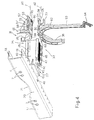
- Figure 1 shows a front view in perspective of a sanitary fixture installation structure, in particular for a lavatory with a flush tank, featuring a pipe fastening device in accordance with the invention;
- Figure 2 shows a partial rear view in perspective of the Figure 1 structure, and an exploded view of the fastening device;
- Figure 3 shows a larger-scale detail of the Figure 1 structure;
- Figure 4 shows an exploded view of the fastening device.
- With reference to Figures 1 and 2, an
installation structure 1 for recessing sanitary fixtures, in particular a lavatory with a flush tank, comprises aframe 2, e.g. made of metal, having twoposts 3, and acrossbar 4 betweenposts 3; and a knownflush tank 6 is fixed toposts 3 by known connecting members (not shown for the sake of simplicity). - Crossbar 4 has
couplings 7 for attachment of a sanitary fixture - in the example shown, a known lavatory bowl (not shown) - and which are defined, for example, by openings or holes for insertion of known supports and relative locking members not shown. - Crossbar 4 supports two
pipes pipe connecting tank 6 to the lavatory bowl, and by a drain bend connecting the lavatory bowl to an external drain. - Both
pipes main portions respective end portions main portions - With reference also to Figures 3 and 4, crossbar 4 - made, for example, of a metal section - has a substantially U-shaped cross section; a
front wall 17 withcouplings 7; and two, respectively top and bottom,flanges wall 17. Crossbar 4 comprises acentral portion 20 having adip 21housing end portion 15 ofpipe 11; andcentral portion 20 has acavity 22 bounded bywall 17 andflanges -
Structure 1 has afastening device 25 forfastening pipes structure 1, and in particular tocrossbar 4. -
Device 25 comprises a supportingmember 26 fixable releasably to crossbar 4 by a click-oncoupling 27; and twoindependent fastening assemblies member 26 to fastenrespective pipes member 26 by means of respectiveintermediate members member 26 and havingrespective seats pipes - Supporting
member 26 has a prismatic, moldedplastic body 40, and comprises two opposite, respectively top and bottom,faces portion 43 for connection tocrossbar 4 and which fits insidecavity 22. Click-oncoupling 27 comprises a tooth 44 carried by a flexible tongue 45, formed onbottom face 42 of supportingmember 26, and which clicks inside aseat 46, formed inflange 19 ofcrossbar 4, when connectingportion 43 is inserted insidecavity 22. -
Faces respective racks respective guides racks respective guides racks guides rails racks guides - Adjustment axes A1, A2 are parallel to each other and to end
portions pipes -
Intermediate members respective slides 53, 54, which run insideguides releasable stops racks -
Slides 53, 54 compriserespective base plates longitudinal ribs base plates rails -
Base plates respective collars seats collar 61 is designed to flex radially and click ontoend portion 15 ofpipe 11, whereascollar 62 is fitted onto and tightened aboutend portion 16 ofpipe 12 by means of aflexible strap 63 fitted with afastening mechanism 64. -
Stops flexible tabs base plates respective cuts base plates base plates respective root edges Tabs tabs - In actual use, to fasten
pipes structure 1, the fitterinserts connecting portion 43 of supportingmember 26 insidecavity 22, so that tooth 44 engagesseat 46. -
Intermediate member 33 is then fitted to supportingmember 26, by insertingslide 53 inside guide 49 (through one of the axially opposite ends ofguide 49, which are both open) and by keepingtab 65 raised so thatstop 55 does not engagerack 47. Whenslide 53 is set to the desired position along adjustment axis A1,tab 65 is released so thatstop 55 engagesrack 47, thus securingintermediate member 33 to supportingmember 26.End portion 15 ofpipe 11 is then inserted insideseat 35. - Similarly,
intermediate member 34 is fitted to supportingmember 26 by inserting slide 54 insideguide 50, withstop 56 raised to avoid engagingrack 48; slide 54 is set to the desired position along adjustment axis A2, andstop 56 is released to engagerack 48; andend portion 16 ofpipe 12 is then inserted insideseat 36 and locked bycollar 62. - Fastening assemblies 31, 32 thus provide for adjusting the positions of
pipes member 26 and along adjustment axes A1, A2, independently of each other. - Clearly, changes may be made to what is described and illustrated herein without, however, departing from the scope of the accompanying Claims.
Claims (15)
- A device (25) for fastening pipes to a sanitary fixture installation structure (1), in particular for a lavatory with a flush tank, the device comprising a bar (4) carried by the structure; and a supporting member (26) fixable to the bar and having first fastening means (31) for fastening a first pipe (11) to the supporting member; the device being characterized in that the supporting member (26) has second fastening means (32) for fastening a second pipe (12) to the supporting member (26) .
- A device as claimed in Claim 1, characterized in that said first fastening means (31) are adjustable fastening means for adjusting the position of said first pipe (11), with respect to said supporting member (26), along an adjustment axis (A1).
- A device as claimed in Claim 1 or 2, characterized in that said first fastening means (31) comprise a rack (47) associated with a guide (49) ; and a slide (53) which slides inside the guide (49); the rack (47) and the guide (49) extending along an adjustment axis (A1); and the slide (53) sliding inside the guide (49) along the adjustment axis (A1), and having a releasable stop (55) cooperating with the rack (47).
- A device as claimed in Claim 3, characterized in that the stop (55) is carried by a flexible tab (65) formed on the slide (53) and having opposite faces respectively supporting said stop (55) and a user operating lever (71).
- A device as claimed in Claim 3 or 4, characterized in that the slide (53) comprises a base plate (57) having two longitudinal ribs (59) inserted inside respective rails (51) of the guide (49).
- A device as claimed in Claim 5, characterized in that the tab (65) is defined by a portion of the base plate (57) bounded by a cut (67) through the base plate (57) and attached to the base plate (57) by a root edge (69).
- A device as claimed in one of Claims 3 to 6, characterized in that the rack (47) and the guide (49) are carried by the supporting member (26).
- A device as claimed in one of the foregoing Claims, characterized in that the supporting member (26) supports independent first and second adjustable fastening means (31, 32) for adjusting the positions of the first and second pipe (11, 12), with respect to the supporting member (26), along respective adjustment axes (A1, A2) and independently of each other.
- A device as claimed in Claim 8, characterized in that said adjustment axes (A1, A2) are parallel to each other.
- A device as claimed in Claim 8 or 9, characterized in that said first and second adjustable fastening means (31, 32) comprise respective racks (47, 48) carried by the supporting member (26) and associated with respective guides (49, 50); and respective slides (53, 54) which slide inside said guides (49, 50); the racks (47, 48) and the respective guides (49, 50) extending along respective adjustment axes (A1, A2); and the slides (53, 54) sliding inside the guides (49, 50) along said adjustment axes (A1, A2), and having respective releasable stops (55, 56) cooperating with the racks (47, 48).
- A device as claimed in one of the foregoing Claims, characterized in that said first and second fastening means (31, 32) comprise respective intermediate members (33, 34) fixable to the supporting member (26) and having respective seats (35, 36) for said pipes (11, 12).
- A device as claimed in one of the foregoing Claims, characterized in that said first and second fastening means (31, 32) are located on opposite sides of the supporting member (26).
- A device as claimed in one of the foregoing Claims, characterized in that the supporting member (26) is fixable releasably to the bar (4) by a click-on coupling (27).
- A device as claimed in Claim 13, characterized in that the click-on coupling (27) comprises a tooth (44) carried by a flexible tongue (45), formed on the supporting member (26), and which clicks inside a seat (46) formed in the bar (4) .
- A device as claimed in one of the foregoing Claims, characterized in that the second pipe (12) is a drain bend connecting a sanitary fixture, fitted to the structure (1), to an external drain, and the first pipe (11) is a flush pipe connecting a flush tank (6) to said sanitary fixture.
Priority Applications (1)
| Application Number | Priority Date | Filing Date | Title |
|---|---|---|---|
| PL05112729T PL1674627T3 (en) | 2004-12-24 | 2005-12-22 | Device for fastening pipes to a sanitary fixture installation structure, in particular for a lavatory with a flush tank |
Applications Claiming Priority (1)
| Application Number | Priority Date | Filing Date | Title |
|---|---|---|---|
| IT002511A ITMI20042511A1 (en) | 2004-12-24 | 2004-12-24 | PIPE FIXING DEVICE FOR AN INSTALLATION STRUCTURE FOR SANITARY WARE IN PARTICULAR FOR A WC WITH A RINSING DRAWER |
Publications (3)
| Publication Number | Publication Date |
|---|---|
| EP1674627A2 true EP1674627A2 (en) | 2006-06-28 |
| EP1674627A3 EP1674627A3 (en) | 2006-11-02 |
| EP1674627B1 EP1674627B1 (en) | 2009-02-11 |
Family
ID=36090836
Family Applications (1)
| Application Number | Title | Priority Date | Filing Date |
|---|---|---|---|
| EP05112729A Expired - Lifetime EP1674627B1 (en) | 2004-12-24 | 2005-12-22 | Device for fastening pipes to a sanitary fixture installation structure, in particular for a lavatory with a flush tank |
Country Status (7)
| Country | Link |
|---|---|
| EP (1) | EP1674627B1 (en) |
| AT (1) | ATE422583T1 (en) |
| DE (1) | DE602005012665D1 (en) |
| IT (1) | ITMI20042511A1 (en) |
| NO (1) | NO20056079L (en) |
| PL (1) | PL1674627T3 (en) |
| RU (1) | RU2005140298A (en) |
Cited By (2)
| Publication number | Priority date | Publication date | Assignee | Title |
|---|---|---|---|---|
| EP2295651A1 (en) | 2009-07-29 | 2011-03-16 | Geberit International AG | Assembly aid for positioning an in-wall cistern in a wall break and flushing device with such an assembly aid |
| US20230138187A1 (en) * | 2021-10-29 | 2023-05-04 | Zhongshan Meitu Plastic Ind. Co., Ltd. | Mounting bracket |
Family Cites Families (4)
| Publication number | Priority date | Publication date | Assignee | Title |
|---|---|---|---|---|
| US2384158A (en) * | 1945-02-12 | 1945-09-04 | Arley D Carpenter | Hanger |
| GB749643A (en) * | 1953-08-12 | 1956-05-30 | Bryson Brackets Ltd | Improvements in or relating to adjustable supports |
| GB1134255A (en) * | 1966-11-09 | 1968-11-20 | Westland Aircraft Ltd | Improvements in or relating to clip arrangements for pipes, cables, and the like |
| DE8000819U1 (en) * | 1980-01-15 | 1980-05-29 | Gebr. Knauf Westdeutsche Gipswerke, 8715 Iphofen | SUPPORTING STAND OF AN ASSEMBLY WALL |
-
2004
- 2004-12-24 IT IT002511A patent/ITMI20042511A1/en unknown
-
2005
- 2005-12-21 NO NO20056079A patent/NO20056079L/en not_active Application Discontinuation
- 2005-12-22 DE DE602005012665T patent/DE602005012665D1/en not_active Expired - Lifetime
- 2005-12-22 EP EP05112729A patent/EP1674627B1/en not_active Expired - Lifetime
- 2005-12-22 AT AT05112729T patent/ATE422583T1/en not_active IP Right Cessation
- 2005-12-22 PL PL05112729T patent/PL1674627T3/en unknown
- 2005-12-23 RU RU2005140298/03A patent/RU2005140298A/en not_active Application Discontinuation
Cited By (3)
| Publication number | Priority date | Publication date | Assignee | Title |
|---|---|---|---|---|
| EP2295651A1 (en) | 2009-07-29 | 2011-03-16 | Geberit International AG | Assembly aid for positioning an in-wall cistern in a wall break and flushing device with such an assembly aid |
| US20230138187A1 (en) * | 2021-10-29 | 2023-05-04 | Zhongshan Meitu Plastic Ind. Co., Ltd. | Mounting bracket |
| US11965621B2 (en) * | 2021-10-29 | 2024-04-23 | Zhongshan Meitu Plastic Ind. Co., Ltd. | Mounting bracket |
Also Published As
| Publication number | Publication date |
|---|---|
| RU2005140298A (en) | 2007-06-27 |
| EP1674627A3 (en) | 2006-11-02 |
| ATE422583T1 (en) | 2009-02-15 |
| ITMI20042511A1 (en) | 2005-03-24 |
| PL1674627T3 (en) | 2009-07-31 |
| NO20056079L (en) | 2006-06-26 |
| EP1674627B1 (en) | 2009-02-11 |
| DE602005012665D1 (en) | 2009-03-26 |
Similar Documents
| Publication | Publication Date | Title |
|---|---|---|
| US9853431B2 (en) | Electrical box bracket | |
| US8403277B2 (en) | Electrical box mounting bracket | |
| US5060892A (en) | Plumbing hanger bracket assembly | |
| EP2031179B1 (en) | Bracket for mounting a guiding rail | |
| CN101511225B (en) | Drawer | |
| JP5992617B2 (en) | Clip for attaching grid runner to edge trim | |
| DK2646726T3 (en) | pipe clamp | |
| US20150257857A1 (en) | Orthodontic connector assembly and a method for treating teeth | |
| US20080272076A1 (en) | Shelf mounting system | |
| CA2389198C (en) | Retainer clip for mounting sink to countertop | |
| AU2015201394B2 (en) | Fastening device for making support frames of sanitary appliances | |
| US8523119B1 (en) | Pipe support bracket | |
| EP1674622A1 (en) | Adjustable device for fastening pipes to a sanitary fixture installation structure, in particular for a lavatory with a flush tank | |
| EP1674627B1 (en) | Device for fastening pipes to a sanitary fixture installation structure, in particular for a lavatory with a flush tank | |
| CN110149799A (en) | Means for attaching solar panels | |
| US8020895B2 (en) | Device comprising an outflow bend and a pipe clamp and mounting structure comprising such a device | |
| CN112219328B (en) | Separating web for an energy guiding chain | |
| EP1944843B1 (en) | Device for fastening a component supporting rail to the frame of an electrical control panel | |
| US20190211999A1 (en) | Retention Devices for Recessed Luminaires | |
| DK165147B (en) | Device for connection of an installation duct which can be disconnected | |
| AU727619B2 (en) | Attachment accessory for a sanitary element | |
| TW202011869A (en) | Pull-out guide for drawers provided with a device for the height adjustment of the drawer | |
| EP3287566A1 (en) | Flushing tank with an adjustable wall-mounting device | |
| EP4190215A1 (en) | Fastening device for fastening a seat assembly onto a sanitary bowl | |
| JP3908427B2 (en) | Kick cover installation position adjustment device |
Legal Events
| Date | Code | Title | Description |
|---|---|---|---|
| PUAI | Public reference made under article 153(3) epc to a published international application that has entered the european phase |
Free format text: ORIGINAL CODE: 0009012 |
|
| AK | Designated contracting states |
Kind code of ref document: A2 Designated state(s): AT BE BG CH CY CZ DE DK EE ES FI FR GB GR HU IE IS IT LI LT LU LV MC NL PL PT RO SE SI SK TR |
|
| AX | Request for extension of the european patent |
Extension state: AL BA HR MK YU |
|
| PUAL | Search report despatched |
Free format text: ORIGINAL CODE: 0009013 |
|
| AK | Designated contracting states |
Kind code of ref document: A3 Designated state(s): AT BE BG CH CY CZ DE DK EE ES FI FR GB GR HU IE IS IT LI LT LU LV MC NL PL PT RO SE SI SK TR |
|
| AX | Request for extension of the european patent |
Extension state: AL BA HR MK YU |
|
| 17P | Request for examination filed |
Effective date: 20070430 |
|
| AKX | Designation fees paid |
Designated state(s): AT BE BG CH CY CZ DE DK EE ES FI FR GB GR HU IE IS IT LI LT LU LV MC NL PL PT RO SE SI SK TR |
|
| 17Q | First examination report despatched |
Effective date: 20070627 |
|
| GRAP | Despatch of communication of intention to grant a patent |
Free format text: ORIGINAL CODE: EPIDOSNIGR1 |
|
| GRAS | Grant fee paid |
Free format text: ORIGINAL CODE: EPIDOSNIGR3 |
|
| GRAA | (expected) grant |
Free format text: ORIGINAL CODE: 0009210 |
|
| AK | Designated contracting states |
Kind code of ref document: B1 Designated state(s): AT BE BG CH CY CZ DE DK EE ES FI FR GB GR HU IE IS IT LI LT LU LV MC NL PL PT RO SE SI SK TR |
|
| REG | Reference to a national code |
Ref country code: GB Ref legal event code: FG4D |
|
| REG | Reference to a national code |
Ref country code: CH Ref legal event code: EP |
|
| REG | Reference to a national code |
Ref country code: IE Ref legal event code: FG4D |
|
| REF | Corresponds to: |
Ref document number: 602005012665 Country of ref document: DE Date of ref document: 20090326 Kind code of ref document: P |
|
| REG | Reference to a national code |
Ref country code: SE Ref legal event code: TRGR |
|
| PG25 | Lapsed in a contracting state [announced via postgrant information from national office to epo] |
Ref country code: ES Free format text: LAPSE BECAUSE OF FAILURE TO SUBMIT A TRANSLATION OF THE DESCRIPTION OR TO PAY THE FEE WITHIN THE PRESCRIBED TIME-LIMIT Effective date: 20090522 Ref country code: NL Free format text: LAPSE BECAUSE OF FAILURE TO SUBMIT A TRANSLATION OF THE DESCRIPTION OR TO PAY THE FEE WITHIN THE PRESCRIBED TIME-LIMIT Effective date: 20090211 Ref country code: FI Free format text: LAPSE BECAUSE OF FAILURE TO SUBMIT A TRANSLATION OF THE DESCRIPTION OR TO PAY THE FEE WITHIN THE PRESCRIBED TIME-LIMIT Effective date: 20090211 Ref country code: SI Free format text: LAPSE BECAUSE OF FAILURE TO SUBMIT A TRANSLATION OF THE DESCRIPTION OR TO PAY THE FEE WITHIN THE PRESCRIBED TIME-LIMIT Effective date: 20090211 Ref country code: LT Free format text: LAPSE BECAUSE OF FAILURE TO SUBMIT A TRANSLATION OF THE DESCRIPTION OR TO PAY THE FEE WITHIN THE PRESCRIBED TIME-LIMIT Effective date: 20090211 |
|
| REG | Reference to a national code |
Ref country code: PL Ref legal event code: T3 |
|
| NLV1 | Nl: lapsed or annulled due to failure to fulfill the requirements of art. 29p and 29m of the patents act | ||
| PG25 | Lapsed in a contracting state [announced via postgrant information from national office to epo] |
Ref country code: AT Free format text: LAPSE BECAUSE OF FAILURE TO SUBMIT A TRANSLATION OF THE DESCRIPTION OR TO PAY THE FEE WITHIN THE PRESCRIBED TIME-LIMIT Effective date: 20090211 Ref country code: LV Free format text: LAPSE BECAUSE OF FAILURE TO SUBMIT A TRANSLATION OF THE DESCRIPTION OR TO PAY THE FEE WITHIN THE PRESCRIBED TIME-LIMIT Effective date: 20090211 Ref country code: IS Free format text: LAPSE BECAUSE OF FAILURE TO SUBMIT A TRANSLATION OF THE DESCRIPTION OR TO PAY THE FEE WITHIN THE PRESCRIBED TIME-LIMIT Effective date: 20090611 |
|
| PG25 | Lapsed in a contracting state [announced via postgrant information from national office to epo] |
Ref country code: BE Free format text: LAPSE BECAUSE OF FAILURE TO SUBMIT A TRANSLATION OF THE DESCRIPTION OR TO PAY THE FEE WITHIN THE PRESCRIBED TIME-LIMIT Effective date: 20090211 |
|
| PG25 | Lapsed in a contracting state [announced via postgrant information from national office to epo] |
Ref country code: EE Free format text: LAPSE BECAUSE OF FAILURE TO SUBMIT A TRANSLATION OF THE DESCRIPTION OR TO PAY THE FEE WITHIN THE PRESCRIBED TIME-LIMIT Effective date: 20090211 Ref country code: DK Free format text: LAPSE BECAUSE OF FAILURE TO SUBMIT A TRANSLATION OF THE DESCRIPTION OR TO PAY THE FEE WITHIN THE PRESCRIBED TIME-LIMIT Effective date: 20090211 Ref country code: PT Free format text: LAPSE BECAUSE OF FAILURE TO SUBMIT A TRANSLATION OF THE DESCRIPTION OR TO PAY THE FEE WITHIN THE PRESCRIBED TIME-LIMIT Effective date: 20090713 Ref country code: CZ Free format text: LAPSE BECAUSE OF FAILURE TO SUBMIT A TRANSLATION OF THE DESCRIPTION OR TO PAY THE FEE WITHIN THE PRESCRIBED TIME-LIMIT Effective date: 20090211 |
|
| PG25 | Lapsed in a contracting state [announced via postgrant information from national office to epo] |
Ref country code: RO Free format text: LAPSE BECAUSE OF FAILURE TO SUBMIT A TRANSLATION OF THE DESCRIPTION OR TO PAY THE FEE WITHIN THE PRESCRIBED TIME-LIMIT Effective date: 20090211 Ref country code: SK Free format text: LAPSE BECAUSE OF FAILURE TO SUBMIT A TRANSLATION OF THE DESCRIPTION OR TO PAY THE FEE WITHIN THE PRESCRIBED TIME-LIMIT Effective date: 20090211 |
|
| PLBE | No opposition filed within time limit |
Free format text: ORIGINAL CODE: 0009261 |
|
| STAA | Information on the status of an ep patent application or granted ep patent |
Free format text: STATUS: NO OPPOSITION FILED WITHIN TIME LIMIT |
|
| 26N | No opposition filed |
Effective date: 20091112 |
|
| PG25 | Lapsed in a contracting state [announced via postgrant information from national office to epo] |
Ref country code: BG Free format text: LAPSE BECAUSE OF FAILURE TO SUBMIT A TRANSLATION OF THE DESCRIPTION OR TO PAY THE FEE WITHIN THE PRESCRIBED TIME-LIMIT Effective date: 20090511 |
|
| EUG | Se: european patent has lapsed | ||
| PG25 | Lapsed in a contracting state [announced via postgrant information from national office to epo] |
Ref country code: MC Free format text: LAPSE BECAUSE OF NON-PAYMENT OF DUE FEES Effective date: 20100701 |
|
| REG | Reference to a national code |
Ref country code: CH Ref legal event code: PL |
|
| GBPC | Gb: european patent ceased through non-payment of renewal fee |
Effective date: 20091222 |
|
| REG | Reference to a national code |
Ref country code: IE Ref legal event code: MM4A |
|
| PG25 | Lapsed in a contracting state [announced via postgrant information from national office to epo] |
Ref country code: LI Free format text: LAPSE BECAUSE OF NON-PAYMENT OF DUE FEES Effective date: 20091231 Ref country code: IE Free format text: LAPSE BECAUSE OF NON-PAYMENT OF DUE FEES Effective date: 20091222 Ref country code: CH Free format text: LAPSE BECAUSE OF NON-PAYMENT OF DUE FEES Effective date: 20091231 Ref country code: GR Free format text: LAPSE BECAUSE OF FAILURE TO SUBMIT A TRANSLATION OF THE DESCRIPTION OR TO PAY THE FEE WITHIN THE PRESCRIBED TIME-LIMIT Effective date: 20090512 |
|
| PG25 | Lapsed in a contracting state [announced via postgrant information from national office to epo] |
Ref country code: GB Free format text: LAPSE BECAUSE OF NON-PAYMENT OF DUE FEES Effective date: 20091222 |
|
| PG25 | Lapsed in a contracting state [announced via postgrant information from national office to epo] |
Ref country code: IT Free format text: LAPSE BECAUSE OF FAILURE TO SUBMIT A TRANSLATION OF THE DESCRIPTION OR TO PAY THE FEE WITHIN THE PRESCRIBED TIME-LIMIT Effective date: 20090211 |
|
| PG25 | Lapsed in a contracting state [announced via postgrant information from national office to epo] |
Ref country code: LU Free format text: LAPSE BECAUSE OF NON-PAYMENT OF DUE FEES Effective date: 20091222 |
|
| PG25 | Lapsed in a contracting state [announced via postgrant information from national office to epo] |
Ref country code: SE Free format text: LAPSE BECAUSE OF NON-PAYMENT OF DUE FEES Effective date: 20091223 |
|
| PG25 | Lapsed in a contracting state [announced via postgrant information from national office to epo] |
Ref country code: HU Free format text: LAPSE BECAUSE OF FAILURE TO SUBMIT A TRANSLATION OF THE DESCRIPTION OR TO PAY THE FEE WITHIN THE PRESCRIBED TIME-LIMIT Effective date: 20090812 |
|
| PG25 | Lapsed in a contracting state [announced via postgrant information from national office to epo] |
Ref country code: TR Free format text: LAPSE BECAUSE OF FAILURE TO SUBMIT A TRANSLATION OF THE DESCRIPTION OR TO PAY THE FEE WITHIN THE PRESCRIBED TIME-LIMIT Effective date: 20090211 |
|
| PG25 | Lapsed in a contracting state [announced via postgrant information from national office to epo] |
Ref country code: CY Free format text: LAPSE BECAUSE OF FAILURE TO SUBMIT A TRANSLATION OF THE DESCRIPTION OR TO PAY THE FEE WITHIN THE PRESCRIBED TIME-LIMIT Effective date: 20090211 |
|
| REG | Reference to a national code |
Ref country code: FR Ref legal event code: PLFP Year of fee payment: 11 |
|
| PGFP | Annual fee paid to national office [announced via postgrant information from national office to epo] |
Ref country code: DE Payment date: 20151215 Year of fee payment: 11 |
|
| PGFP | Annual fee paid to national office [announced via postgrant information from national office to epo] |
Ref country code: PL Payment date: 20151113 Year of fee payment: 11 |
|
| REG | Reference to a national code |
Ref country code: FR Ref legal event code: PLFP Year of fee payment: 12 |
|
| REG | Reference to a national code |
Ref country code: DE Ref legal event code: R119 Ref document number: 602005012665 Country of ref document: DE |
|
| PG25 | Lapsed in a contracting state [announced via postgrant information from national office to epo] |
Ref country code: DE Free format text: LAPSE BECAUSE OF NON-PAYMENT OF DUE FEES Effective date: 20170701 |
|
| REG | Reference to a national code |
Ref country code: FR Ref legal event code: PLFP Year of fee payment: 13 |
|
| PGFP | Annual fee paid to national office [announced via postgrant information from national office to epo] |
Ref country code: FR Payment date: 20171226 Year of fee payment: 13 |
|
| PG25 | Lapsed in a contracting state [announced via postgrant information from national office to epo] |
Ref country code: PL Free format text: LAPSE BECAUSE OF NON-PAYMENT OF DUE FEES Effective date: 20161222 |
|
| PG25 | Lapsed in a contracting state [announced via postgrant information from national office to epo] |
Ref country code: FR Free format text: LAPSE BECAUSE OF NON-PAYMENT OF DUE FEES Effective date: 20181231 |