EP1674217A1 - Apparatus for storing accessory cases - Google Patents
Apparatus for storing accessory cases Download PDFInfo
- Publication number
- EP1674217A1 EP1674217A1 EP05257919A EP05257919A EP1674217A1 EP 1674217 A1 EP1674217 A1 EP 1674217A1 EP 05257919 A EP05257919 A EP 05257919A EP 05257919 A EP05257919 A EP 05257919A EP 1674217 A1 EP1674217 A1 EP 1674217A1
- Authority
- EP
- European Patent Office
- Prior art keywords
- retaining
- support plate
- accessory
- accessory cases
- cases
- Prior art date
- Legal status (The legal status is an assumption and is not a legal conclusion. Google has not performed a legal analysis and makes no representation as to the accuracy of the status listed.)
- Granted
Links
- 230000008878 coupling Effects 0.000 claims description 24
- 238000010168 coupling process Methods 0.000 claims description 24
- 238000005859 coupling reaction Methods 0.000 claims description 24
- 230000002093 peripheral effect Effects 0.000 claims description 3
- 238000010276 construction Methods 0.000 description 3
- 229910052751 metal Inorganic materials 0.000 description 2
- 239000002184 metal Substances 0.000 description 2
- 239000004411 aluminium Substances 0.000 description 1
- 229910052782 aluminium Inorganic materials 0.000 description 1
- XAGFODPZIPBFFR-UHFFFAOYSA-N aluminium Chemical compound [Al] XAGFODPZIPBFFR-UHFFFAOYSA-N 0.000 description 1
Images





Classifications
-
- B—PERFORMING OPERATIONS; TRANSPORTING
- B25—HAND TOOLS; PORTABLE POWER-DRIVEN TOOLS; MANIPULATORS
- B25H—WORKSHOP EQUIPMENT, e.g. FOR MARKING-OUT WORK; STORAGE MEANS FOR WORKSHOPS
- B25H3/00—Storage means or arrangements for workshops facilitating access to, or handling of, work tools or instruments
- B25H3/02—Boxes
- B25H3/021—Boxes comprising a number of connected storage elements
- B25H3/023—Boxes comprising a number of connected storage elements movable relative to one another for access to their interiors
- B25H3/025—Boxes comprising a number of connected storage elements movable relative to one another for access to their interiors by rotation about a common axis
Definitions
- the present invention relates to an improved apparatus for storing accessory cases.
- the apparatus may be made of metal or plastic. Certain apparatus are provided with multiple independent accessory cases which can be ordered in any sequence. Other apparatus are provided with multiple independent accessory cases which are pivotal with respect to each other.
- US-A-5259502 discloses an assembly of multiple tool cases which are connected to each other by an axle or inserting rod so that they are pivotal with respect to the axle or inserting rod such that the tool case can be selectively opened.
- the assembly of tool cases forms a compact construction.
- these tool cases are inconvenient and difficult to disassemble (for example when a case is broken and needs to be repaired).
- the assembly cannot be conveniently disassembled for carriage or transport.
- the present invention seeks to overcome certain disadvantages of conventional apparatus for storing accessory cases by providing an improved apparatus that is assembled and disassembled straightforwardly.
- the present invention provides an apparatus for storing a plurality of accessory cases comprising:
- the present invention provides an apparatus that comprises multiple cases capable of storing power tool accessories and a carousel.
- the carousel may comprise support plates with grooves on it and retaining covers.
- the accessory cases are pivotal with respect to the support plates.
- Each accessory case can be dismounted when the accessory case pivots to align with the grooves.
- the use of accessory cases become very convenient.
- An accessory case can be straightforwardly dismounted from the apparatus and be carried by the user without the need for the whole apparatus to be carried.
- the carousel is horizontally disposed.
- each accessory case is selectively dismountable from the carousel only at a single rotationally selected position.
- the carousel comprises:
- Each retaining cover is typically cup-shaped (eg with a concave inner face).
- the or each support plate may be mounted at the rear face of the retaining cover (eg on support ribs upstanding from the concave inner face).
- each retaining cover comprises a retaining collar or retaining flange for retaining the plurality of accessory cases in the substantially radial position, wherein each retaining collar or retaining flange has a groove and wherein the grooves of each retaining collar or retaining flange are in axial alignment so as to permit one of the plurality of accessory cases when rotationally aligned with the grooves to be dismounted radially.
- the retaining collar or retaining flange is typically an extension of the concave inner face.
- the at least one support plate is a pair of support plates joined to opposite ends of the rotary connection shaft and supported at the rear face of the retaining covers.
- each accessory case comprises a pair of lateral sliding members slidable through the grooves into a rear volume of the retaining cover
- each support plate comprises a plurality of circumferentially spaced apart radial guide slots through each of which the lateral sliding member is slidable into the rear volume of the retaining cover.
- each retaining cover comprises a retaining collar extending axially to a lateral edge of the plurality of accessory cases to confine the lateral sliding member in the rear volume of the retaining cover whereby to retain the plurality of accessory cases in the substantially radial position.
- each accessory case further comprises a guide block adjacent to each sliding member, wherein each radial guide slots comprises a first slot portion and a second slot portion communicating with the first slot portion, wherein the guide block is slidable into the first slot portion and the width of the second slot portion is greater than the width of the first slot portion so that the lateral sliding member is slidable through and out of the second slot portion into the rear volume of the retaining cover.
- each support plate further comprises a plurality of axially projecting guide walls surrounding each radial guide slot to slidingly receive the lateral edge of the accessory cases.
- the at least one support plate is a single support plate joined to an end of the rotary connection shaft and supported at the rear face of one of the retaining covers.
- the support plate comprises a plate body supported at the rear face of one of the retaining covers and multiple pairs of radial guide arms extending axially from the plate body.
- each retaining cover comprises a retaining flange extending axially beyond a peripheral edge of the plurality of accessory cases to retain the plurality of accessory cases in the substantially radial position.
- each support plate comprises:
- the number of apertures, the number of radial guide slots and the number of accessory cases is equal.
- the apparatus further comprises:
- the apparatus further comprises:
- the union body may pass through the central aperture of the first retaining cover and the hub hole of the support plate.
- the union body may have a radial projection inserted into a slot of the support plate.
- An end of the coupling rod may be sleeved on the union body and may have a slot in which is inserted the radial projection.
- the connection piece may pass through the central aperture of the retaining cover and an end of the coupling rod may be sleeved on the connection piece.
- the apparatus further comprises:
- the rotary connection shaft is positioned between the retaining covers and is connected to the rotary support plates, wherein the rotary connection shaft comprises:
- the carousel further comprises:
- each supporting bracket comprises: a fixing member for fixing the apparatus to a fixed surface.
- the supporting bracket is typically substantially U-shaped.
- an apparatus comprises multiple accessory cases 2 supported radially in a horizontally disposed carousel 8.
- the carousel comprises a pair of support plates 4 fixed to opposite ends of a rotary connection shaft 6.
- Each support plate 4 is made of plastic and is substantially circular.
- the carousel 8 further comprises a pair of substantially U-shaped support brackets 82a,b which are connected in divergent fashion to a pair of axially spaced apart retaining covers 84a,b.
- Each retaining cover 84a,b is substantially cup-shaped with a central aperture 840 and a concave inner face 86 extending into an axial retaining collar 88a.
- Each support plate 4 is supported at the rear face of one of the retaining covers 84a,b on support ribs upstanding from the concave inner face 86.
- the multiple accessory cases 2 may be used to store different accessories of various kinds of power tool (not shown) such as screw and drill bits.
- Each accessory case 2 comprises a base body 21 and a transparent cover 23.
- Various compartments are disposed in the base body 21 for receiving accessories.
- On each lateral edge of the accessory case 2 is disposed a sliding member 27 and an adjacent guide block 29.
- the sliding member 27 is substantially cylindrical and the guide block 29 is substantially cuboidal.
- each of a plurality of stirrups 83 are disposed radially on the concave inner face 86 of the retaining cover 84a,b to receive an end of the bracket 82a,b.
- the brackets 82a,b are made of a metal such as aluminium and the retaining covers 84a,b are made of plastic.
- Each bracket 82a,b is provided with a fixing plate 820 so as to fix the apparatus (if desired) to the ground or a wall with screws.
- a groove 88 is disposed in the retaining collar 88a and the grooves 88 in the pair of retaining covers 84a,b are in axial alignment.
- the diameter of the concave inner face 86 is a little greater than the diameter of the sliding member 27 such that the sliding member 27 is capable of sliding into the concavity.
- An annular support rib 81 is disposed on the concave inner face 86 to support the periphery of the sliding member 27.
- the axial retaining collar 88a extends axially to a lateral edge of the plurality of accessory cases 2 to confine the lateral sliding member 27 in the concavity.
- a plurality of radial guide slots 42 are equidistantly spaced circumferentially on each support plate 4.
- the number of radial slots 42 matches the maximum number of accessory cases 2.
- Each radial guide slot 42 comprises a first slot portion 44 and a second slot portion 46.
- the width of the first slot portion 44 is substantially equal to the width of the guide block 29 and the width of the second slot portion 46 is greater than the first slot portion 44.
- An aperture 43 is located in the support plate 4 between each radial guide slot 42 and the apertures 43 are substantially equidistantly spaced apart.
- Each support plate 4 also contains a hub hole 41 and a third slot 48 communicating with the hub hole 41.
- a positioning hole 85 is arranged on one of the retaining covers 84a.
- a part of a positioning cam 89 fixed to a spring 87 extends out of the positioning hole 85.
- the positioning cam 89 is urged into an aperture 43 via the action of the spring 87 when the support plate 4 pivots to a certain angle with respect to the retaining cover 84a so that the retaining cover 84a and the support plate 4 can be fixed together firmly.
- the apparatus further comprises a knob 5 for manually rotating the accessory cases 2.
- the knob 5 is disposed on the outer convex face of one of the retaining covers 84a.
- a locating member 9 is positioned between the knob 5 and the retaining cover 84a.
- the rotary connection shaft 6 includes a union body 62 passing through the central aperture 840 of the retaining cover 84a and the hub hole 41 of the support plate 4.
- the union body 62 has a radial projection 64 inserted into the third slot 48 of the support plate 4.
- the rotary connection shaft 6 also comprises a coupling rod 66, a connection piece 68 and a clamping bolt 61 which is inserted in the knob 5 to fix the components firmly together.
- one end of the coupling rod 66 is sleeved on the union body 62 and has a fourth slot 63 in which is inserted the radial projection 64.
- the connection piece 68 passes through the central aperture 840 of the retaining cover 84a and an end of the coupling rod 66 is sleeved on the connection piece 68.
- the connection (not shown) between the connection piece 68 and support plate 4 is the same as the connection between the union body 62 and the coupling rod 66 (see Figure 9).
- the brackets 82a,b are firstly inserted into the retaining covers 84a,b by fixing them firmly in the stirrups 83.
- the support plates 4 are positioned at the rear faces of corresponding retaining covers 84a,b such that one of the radial guide slots 42 aligns with the grooves 88 and the position cam 89 is inserted into a corresponding opening 43 of the support plate 4.
- the coupling rod 66 with the hollow interior is inserted into the support plates 4 and is aligned with the hub holes 41.
- the locating member 9 is sleeved on the union body 62.
- the knob 5 is inserted into the central aperture 840 of the corresponding retaining cover 84 and hub hole 41 of the support plate 4.
- the projection 64 of the union body 62 is inserted into the third slot 48 of the support plate 4 and the fourth slot 63 of the coupling rod 66.
- the connection piece 68 is then connected to the coupling rod 66.
- the clamping bolt 61 is inserted in the knob 5, union body 62, coupling rod 66 and connection piece 68 to fasten them together.
- the sliding members 27 are inserted into corresponding grooves 88 of the retaining covers 84a,b so that the two guide blocks 29 insert into the first slot portions 44.
- the two sliding members 27 pass through the second slot portion 46 and are received in the concavity.
- the knob 5 is rotated until the positioning cam 89 is urged into the aperture 43 of the support plate 4. Further radial guide slots 42 of support plates 4 may be selectively rotated to align with the grooves for other accessory cases to be added in the same fashion.
- an accessory case 2 is rotated (directly or using the knob 5) into alignment with the grooves 88. The accessory case 2 can then be dismounted from the apparatus conveniently.
- Each accessory case 2' is provided with a pair of cylindrical sliding members 27' but no guide blocks (29 in the first embodiment).
- Each sliding member 27' is inserted into a groove 88' of the retaining cover 84'a,b, passes through the radial guide slot 43' and is received in the concavity of the retaining cover 84a,b defined by the concave inner surface 86'.
- Each support plate 4' further comprises a plurality of projecting guide walls 45 surrounding each radial guide slot 43 to slidingly receive the lateral edge of the accessory cases 2'.
- FIG. 15 and 17 there is illustrated a third embodiment of the invention.
- the construction is similar to the first and second embodiments and so reference numerals are shared and the detailed description will be brief.
- the apparatus is provided with a support plate 50 supported between the retaining cover 84"a and an edge of the multiple accessory cases 2". Multiple pairs of radial guide arms 52 extend axially away from the support plate 50. Each accessory case 2" can be inserted between a pair of radial guide arms 52.
- Each retaining cover 84"a,b extends axially inwardly into an annular retaining flange 844 covering the peripheral end of the accessory cases 2" so as to retain the accessory cases 2" in the support plates 50. When the accessory case 2 rotates to align with the groove 88", it can be removed.
Landscapes
- Engineering & Computer Science (AREA)
- Mechanical Engineering (AREA)
- Purses, Travelling Bags, Baskets, Or Suitcases (AREA)
- Casings For Electric Apparatus (AREA)
Abstract
Description
- The present invention relates to an improved apparatus for storing accessory cases.
- Many types of apparatus for storage or transportation of tools or accessories are commercially available. The apparatus may be made of metal or plastic. Certain apparatus are provided with multiple independent accessory cases which can be ordered in any sequence. Other apparatus are provided with multiple independent accessory cases which are pivotal with respect to each other.
- US-A-5259502 discloses an assembly of multiple tool cases which are connected to each other by an axle or inserting rod so that they are pivotal with respect to the axle or inserting rod such that the tool case can be selectively opened. In this way, the assembly of tool cases forms a compact construction. However these tool cases are inconvenient and difficult to disassemble (for example when a case is broken and needs to be repaired). In addition, the assembly cannot be conveniently disassembled for carriage or transport.
- The present invention seeks to overcome certain disadvantages of conventional apparatus for storing accessory cases by providing an improved apparatus that is assembled and disassembled straightforwardly.
- Thus viewed from one aspect the present invention provides an apparatus for storing a plurality of accessory cases comprising:
- a carousel;
- a plurality of accessory cases for storing power tool accessories mounted substantially radially on the carousel, wherein each of the plurality of accessory cases is selectively dismountable radially from the carousel only at one or more rotationally selected positions.
- In an embodiment, the present invention provides an apparatus that comprises multiple cases capable of storing power tool accessories and a carousel. The carousel may comprise support plates with grooves on it and retaining covers. The accessory cases are pivotal with respect to the support plates. Each accessory case can be dismounted when the accessory case pivots to align with the grooves. In accordance with the invention, the use of accessory cases become very convenient. An accessory case can be straightforwardly dismounted from the apparatus and be carried by the user without the need for the whole apparatus to be carried.
- Typically the carousel is horizontally disposed.
- Preferably each accessory case is selectively dismountable from the carousel only at a single rotationally selected position.
- In a preferred embodiment, the carousel comprises:
- a rotary connection shaft for rotating the plurality of accessory cases;
- at least one support plate joined to an end of the rotary connection shaft,
wherein the or each support plate supports each of the plurality of accessory cases in a substantially radial position; and - a pair of retaining covers mounted adjacent to the ends of the connection shaft to retain each of the plurality of accessory cases in the substantially radial position, wherein each of the plurality of accessory cases is selectively dismountable from the carousel only at one or more positions of the at least one support plate relative to the pair of retaining covers selected by rotation of the at least one support plate.
- Each retaining cover is typically cup-shaped (eg with a concave inner face). The or each support plate may be mounted at the rear face of the retaining cover (eg on support ribs upstanding from the concave inner face).
- Preferably each retaining cover comprises a retaining collar or retaining flange for retaining the plurality of accessory cases in the substantially radial position, wherein each retaining collar or retaining flange has a groove and wherein the grooves of each retaining collar or retaining flange are in axial alignment so as to permit one of the plurality of accessory cases when rotationally aligned with the grooves to be dismounted radially. The retaining collar or retaining flange is typically an extension of the concave inner face.
- Preferably the at least one support plate is a pair of support plates joined to opposite ends of the rotary connection shaft and supported at the rear face of the retaining covers.
- Preferably each accessory case comprises a pair of lateral sliding members slidable through the grooves into a rear volume of the retaining cover
- Particularly preferably each support plate comprises a plurality of circumferentially spaced apart radial guide slots through each of which the lateral sliding member is slidable into the rear volume of the retaining cover.
- Preferably each retaining cover comprises a retaining collar extending axially to a lateral edge of the plurality of accessory cases to confine the lateral sliding member in the rear volume of the retaining cover whereby to retain the plurality of accessory cases in the substantially radial position.
- Preferably each accessory case further comprises a guide block adjacent to each sliding member, wherein each radial guide slots comprises a first slot portion and a second slot portion communicating with the first slot portion, wherein the guide block is slidable into the first slot portion and the width of the second slot portion is greater than the width of the first slot portion so that the lateral sliding member is slidable through and out of the second slot portion into the rear volume of the retaining cover.
- Preferably each support plate further comprises a plurality of axially projecting guide walls surrounding each radial guide slot to slidingly receive the lateral edge of the accessory cases.
- Preferably the at least one support plate is a single support plate joined to an end of the rotary connection shaft and supported at the rear face of one of the retaining covers.
- Particularly preferably the support plate comprises a plate body supported at the rear face of one of the retaining covers and multiple pairs of radial guide arms extending axially from the plate body.
- Preferably each retaining cover comprises a retaining flange extending axially beyond a peripheral edge of the plurality of accessory cases to retain the plurality of accessory cases in the substantially radial position.
- Preferably the or each support plate comprises:
- a plurality of substantially equidistantly spaced apart apertures,
- a biasing member and
- a positioning cam connected to the biasing member, wherein the positioning cam is urged into an aperture via the action of the biasing member when the support plate pivots to a certain angle with respect to the retaining cover so that the retaining cover and the support plate can be fixed firmly together.
- Preferably the number of apertures, the number of radial guide slots and the number of accessory cases is equal.
- Preferably the apparatus further comprises:
- a manually operable knob mounted on an outer face of the retaining cover and connected to the support plate.
- Preferably the apparatus further comprises:
- a locating member arranged between the knob and a first of the retaining covers. Particularly preferably the rotary connection shaft comprises:
- a union body extending from an interior of the knob,
- a connection piece connected to a second of the retaining covers and
- a coupling rod mounted between the union body and connection piece, wherein the union body passes through the first retaining cover and is connected to a first of the support plates and the coupling rod and wherein the connection piece passes through the second retaining cover and is connected to a second of the support plates and the coupling rod.
- The union body may pass through the central aperture of the first retaining cover and the hub hole of the support plate. The union body may have a radial projection inserted into a slot of the support plate. An end of the coupling rod may be sleeved on the union body and may have a slot in which is inserted the radial projection. The connection piece may pass through the central aperture of the retaining cover and an end of the coupling rod may be sleeved on the connection piece.
- Preferably the apparatus further comprises:
- a clamping bolt passing through and fixing the knob, the union body, the coupling rod and the connection piece.
- Preferably the rotary connection shaft is positioned between the retaining covers and is connected to the rotary support plates, wherein the rotary connection shaft comprises:
- a union body inserted in each of the retaining covers, a connection piece and a coupling rod connected between the union body and connection piece, wherein the union body is fixed to the support plate and coupling rod simultaneously and the connection piece is fixed to the support plate and the coupling rod simultaneously.
- Preferably the carousel further comprises:
- one or more supporting brackets for supporting the accessory cases, wherein the brackets are connected in divergent fashion to the pair of axially spaced apart retaining covers. For this purpose, the retaining covers may comprise one or more stirrups connectable to an end of the bracket.
- Particularly preferably each supporting bracket comprises: a fixing member for fixing the apparatus to a fixed surface. The supporting bracket is typically substantially U-shaped.
- Viewed from a further aspect the present invention provides an apparatus for storing accessory cases characterized in that it comprises:
- multiple accessory cases for storing accessories of power tools;
- joint plates which are associated with the accessory cases for locating; and
- support elements having grooves,
- The present invention will now be described in a non-limitative sense with reference to the accompanying Figures in which common reference numerals represent corresponding parts throughout:
- FIGURE 1 is a perspective side view of an apparatus according to a first embodiment of the present invention;
- FIGURE 2 is a front view of the apparatus in FIGURE 1;
- FIGURE 3 is a left view of the apparatus in FIGURE 2;
- FIGURE 4 is a right view of the apparatus in FIGURE 2;
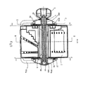
- FIGURE 5 is a cross-sectional view according to the A-A line in FIGURE 4;
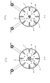
- FIGURE 6 is a cross-sectional view according to the B-B line in FIGURE 5;
- FIGURE 7 is a cross-sectional view according to the C-C line in FIGURE 5;
- FIGURE 8 is a cross-sectional view according to the F-F line in FIGURE 5 (accessory cases removed);
- FIGURE 9 is a cross-sectional view according to the G-G line in FIGURE 5 (accessory cases removed);
- FIGURE 10 is a cross-sectional view according to the D-D line in FIGURE 7;
- FIGURE 11 is a cross-sectional view according to the E-E line in FIGURE 7;
- FIGURE 12 is a side view of an apparatus according to a second embodiment of the present invention;
- FIGURE 13 is a left view of the apparatus in FIGURE 12;
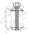
- FIGURE 14 is a cross-sectional view according to the J-J line in FIGURE 13;
- FIGURE 15 is a cross-sectional view of an apparatus according to a third embodiment of the present invention;
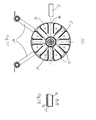
- FIGURE 16 is a cross-sectional view according to the H-H line in FIGURE 15; and
- FIGURE 17 is a cross-sectional view according to the I-I line in FIGURE 15.
- Referring to Figure 1, an apparatus according to a first embodiment of the invention comprises multiple
accessory cases 2 supported radially in a horizontally disposed carousel 8. The carousel comprises a pair ofsupport plates 4 fixed to opposite ends of arotary connection shaft 6. Eachsupport plate 4 is made of plastic and is substantially circular. Referring in particular to Figures 2 to 4 and 7, the carousel 8 further comprises a pair of substantiallyU-shaped support brackets 82a,b which are connected in divergent fashion to a pair of axially spaced apart retainingcovers 84a,b. Each retainingcover 84a,b is substantially cup-shaped with acentral aperture 840 and a concaveinner face 86 extending into anaxial retaining collar 88a. Eachsupport plate 4 is supported at the rear face of one of the retaining covers 84a,b on support ribs upstanding from the concaveinner face 86. - The multiple
accessory cases 2 may be used to store different accessories of various kinds of power tool (not shown) such as screw and drill bits. Eachaccessory case 2 comprises abase body 21 and atransparent cover 23. Various compartments are disposed in thebase body 21 for receiving accessories. On each lateral edge of theaccessory case 2 is disposed a slidingmember 27 and anadjacent guide block 29. The slidingmember 27 is substantially cylindrical and theguide block 29 is substantially cuboidal. - Referring to Figure 10, each of a plurality of
stirrups 83 are disposed radially on the concaveinner face 86 of the retainingcover 84a,b to receive an end of thebracket 82a,b. Thebrackets 82a,b are made of a metal such as aluminium and the retaining covers 84a,b are made of plastic. Eachbracket 82a,b is provided with a fixingplate 820 so as to fix the apparatus (if desired) to the ground or a wall with screws. - A
groove 88 is disposed in the retainingcollar 88a and thegrooves 88 in the pair of retainingcovers 84a,b are in axial alignment. The diameter of the concaveinner face 86 is a little greater than the diameter of the slidingmember 27 such that the slidingmember 27 is capable of sliding into the concavity. Anannular support rib 81 is disposed on the concaveinner face 86 to support the periphery of the slidingmember 27. Theaxial retaining collar 88a extends axially to a lateral edge of the plurality ofaccessory cases 2 to confine thelateral sliding member 27 in the concavity. - Referring to Figures 5, 8 and 9, a plurality of
radial guide slots 42 are equidistantly spaced circumferentially on eachsupport plate 4. The number ofradial slots 42 matches the maximum number ofaccessory cases 2. Eachradial guide slot 42 comprises afirst slot portion 44 and asecond slot portion 46. The width of thefirst slot portion 44 is substantially equal to the width of theguide block 29 and the width of thesecond slot portion 46 is greater than thefirst slot portion 44. Anaperture 43 is located in thesupport plate 4 between eachradial guide slot 42 and theapertures 43 are substantially equidistantly spaced apart. Eachsupport plate 4 also contains ahub hole 41 and a third slot 48 communicating with thehub hole 41. - With reference to Figure 11, a
positioning hole 85 is arranged on one of the retaining covers 84a. A part of apositioning cam 89 fixed to aspring 87 extends out of thepositioning hole 85. Thepositioning cam 89 is urged into anaperture 43 via the action of thespring 87 when thesupport plate 4 pivots to a certain angle with respect to the retainingcover 84a so that the retainingcover 84a and thesupport plate 4 can be fixed together firmly. - Referring to Figures 1 and 5, the apparatus further comprises a
knob 5 for manually rotating theaccessory cases 2. Theknob 5 is disposed on the outer convex face of one of the retaining covers 84a. A locatingmember 9 is positioned between theknob 5 and the retainingcover 84a. Therotary connection shaft 6 includes aunion body 62 passing through thecentral aperture 840 of the retainingcover 84a and thehub hole 41 of thesupport plate 4. Referring to Figure 8, theunion body 62 has aradial projection 64 inserted into the third slot 48 of thesupport plate 4. Therotary connection shaft 6 also comprises acoupling rod 66, aconnection piece 68 and aclamping bolt 61 which is inserted in theknob 5 to fix the components firmly together. Referring to Figure 9, one end of thecoupling rod 66 is sleeved on theunion body 62 and has afourth slot 63 in which is inserted theradial projection 64. Theconnection piece 68 passes through thecentral aperture 840 of the retainingcover 84a and an end of thecoupling rod 66 is sleeved on theconnection piece 68. The connection (not shown) between theconnection piece 68 andsupport plate 4 is the same as the connection between theunion body 62 and the coupling rod 66 (see Figure 9). - Referring to Figure 10, to assemble the first embodiment of the invention, the
brackets 82a,b are firstly inserted into the retaining covers 84a,b by fixing them firmly in thestirrups 83. Referring to Figure 11, thesupport plates 4 are positioned at the rear faces of corresponding retaining covers 84a,b such that one of theradial guide slots 42 aligns with thegrooves 88 and theposition cam 89 is inserted into acorresponding opening 43 of thesupport plate 4. Thecoupling rod 66 with the hollow interior is inserted into thesupport plates 4 and is aligned with the hub holes 41. The locatingmember 9 is sleeved on theunion body 62. Theknob 5 is inserted into thecentral aperture 840 of the corresponding retainingcover 84 andhub hole 41 of thesupport plate 4. Theprojection 64 of theunion body 62 is inserted into the third slot 48 of thesupport plate 4 and thefourth slot 63 of thecoupling rod 66. Theconnection piece 68 is then connected to thecoupling rod 66. The clampingbolt 61 is inserted in theknob 5,union body 62,coupling rod 66 andconnection piece 68 to fasten them together. Referring to Figure 10, the slidingmembers 27 are inserted intocorresponding grooves 88 of the retaining covers 84a,b so that the two guide blocks 29 insert into thefirst slot portions 44. The two slidingmembers 27 pass through thesecond slot portion 46 and are received in the concavity. Theknob 5 is rotated until thepositioning cam 89 is urged into theaperture 43 of thesupport plate 4. Furtherradial guide slots 42 ofsupport plates 4 may be selectively rotated to align with the grooves for other accessory cases to be added in the same fashion. To disassemble the apparatus, anaccessory case 2 is rotated (directly or using the knob 5) into alignment with thegrooves 88. Theaccessory case 2 can then be dismounted from the apparatus conveniently. - Referring to Figures 12 to 14, there is illustrated a second embodiment of the invention. The construction is similar to the first embodiment and so reference numerals are shared and the detailed description will be brief. Each accessory case 2' is provided with a pair of cylindrical sliding members 27' but no guide blocks (29 in the first embodiment). Each sliding member 27' is inserted into a groove 88' of the retaining cover 84'a,b, passes through the radial guide slot 43' and is received in the concavity of the retaining
cover 84a,b defined by the concave inner surface 86'. Each support plate 4' further comprises a plurality of projectingguide walls 45 surrounding eachradial guide slot 43 to slidingly receive the lateral edge of the accessory cases 2'. - With reference to Figures 15 and 17, there is illustrated a third embodiment of the invention. The construction is similar to the first and second embodiments and so reference numerals are shared and the detailed description will be brief. The apparatus is provided with a
support plate 50 supported between the retainingcover 84"a and an edge of the multipleaccessory cases 2". Multiple pairs ofradial guide arms 52 extend axially away from thesupport plate 50. Eachaccessory case 2" can be inserted between a pair ofradial guide arms 52. Each retainingcover 84"a,b extends axially inwardly into anannular retaining flange 844 covering the peripheral end of theaccessory cases 2" so as to retain theaccessory cases 2" in thesupport plates 50. When theaccessory case 2 rotates to align with thegroove 88", it can be removed.
Claims (23)
wherein the or each support plate supports each of the plurality of accessory cases in a substantially radial position; and
and wherein the retaining cover (84a,b) comprises:
wherein the rotary connection shaft comprises:
Applications Claiming Priority (1)
| Application Number | Priority Date | Filing Date | Title |
|---|---|---|---|
| CNU2004200548060U CN2761374Y (en) | 2004-12-27 | 2004-12-27 | Accessory box-assembly |
Publications (2)
| Publication Number | Publication Date |
|---|---|
| EP1674217A1 true EP1674217A1 (en) | 2006-06-28 |
| EP1674217B1 EP1674217B1 (en) | 2008-09-24 |
Family
ID=36094509
Family Applications (1)
| Application Number | Title | Priority Date | Filing Date |
|---|---|---|---|
| EP05257919A Ceased EP1674217B1 (en) | 2004-12-27 | 2005-12-20 | Apparatus for storing accessory cases |
Country Status (4)
| Country | Link |
|---|---|
| US (1) | US7878341B2 (en) |
| EP (1) | EP1674217B1 (en) |
| CN (1) | CN2761374Y (en) |
| DE (1) | DE602005009912D1 (en) |
Cited By (4)
| Publication number | Priority date | Publication date | Assignee | Title |
|---|---|---|---|---|
| CN103796805A (en) * | 2011-08-25 | 2014-05-14 | 迪美科技控股有限公司 | System for storage and transport |
| US9381640B2 (en) | 2010-02-25 | 2016-07-05 | Demain Technology Pty Ltd | Power tool storage and package system |
| WO2016151124A1 (en) * | 2015-03-25 | 2016-09-29 | Thomas Ortner | Bearing insert, shelf and working table |
| CN119660131A (en) * | 2024-12-13 | 2025-03-21 | 安徽万维克林精密装备有限公司 | Rotatable mechanism for placing quartz tube |
Families Citing this family (11)
| Publication number | Priority date | Publication date | Assignee | Title |
|---|---|---|---|---|
| EP2539113A1 (en) * | 2010-02-25 | 2013-01-02 | Demain Technology Pty Ltd. | Power tool and accessory storage system |
| CN103538607A (en) * | 2013-10-23 | 2014-01-29 | 江苏昆鼎数控设备制造有限公司 | Tool trolley |
| CN104608104B (en) * | 2015-01-06 | 2016-06-22 | 建科机械(天津)股份有限公司 | A kind of rotary raw bar material storage device |
| CN104942779B (en) * | 2015-06-16 | 2016-08-24 | 浙江天开实业有限公司 | A kind of assembled instrument cases |
| CN107054853A (en) * | 2017-06-30 | 2017-08-18 | 马鞍山方圆动力科技有限公司 | A kind of portable measurer customization box |
| US10927998B1 (en) * | 2020-04-06 | 2021-02-23 | Peter A. Crockett | Rotatable support structure for supporting elongate objects |
| CN111674681A (en) * | 2020-05-06 | 2020-09-18 | 中自机器人技术(安庆)有限公司 | Sorting storage rack of infusion bag sorting machine |
| CN112659080B (en) * | 2021-01-14 | 2022-04-05 | 浙江力基计量技术有限公司 | Measurement detects toolbox |
| CA3162492C (en) * | 2021-11-12 | 2025-02-25 | Vidir Solutions Inc. | Storage system with movable platforms and internal electrical power distribution system |
| US12599845B2 (en) * | 2023-03-01 | 2026-04-14 | Amazing Pinatas Inc | Piñata structure and method for assembling same |
| US12193566B1 (en) * | 2024-06-26 | 2025-01-14 | Cynosure Holdings, Llc | Rotating organizer |
Citations (6)
| Publication number | Priority date | Publication date | Assignee | Title |
|---|---|---|---|---|
| US2646891A (en) * | 1950-05-11 | 1953-07-28 | George P Morgan | Apparatus for supporting and displaying articles |
| DE949161C (en) * | 1951-03-28 | 1956-09-13 | Hermann Rossteutscher | Mailbox stand |
| US4126366A (en) * | 1977-03-04 | 1978-11-21 | Hirsh Company | Rotatable, multiple storage bin assembly |
| US5259502A (en) | 1993-04-26 | 1993-11-09 | Chan C | Tool case |
| EP1366866A1 (en) * | 2002-05-31 | 2003-12-03 | Global Industries Holdings Ltd. | Double-stack tool rack |
| CA2451537A1 (en) * | 2003-12-24 | 2004-03-20 | Global Industries Holdings Ltd. | Storage rack |
Family Cites Families (8)
| Publication number | Priority date | Publication date | Assignee | Title |
|---|---|---|---|---|
| US1558376A (en) * | 1924-01-30 | 1925-10-20 | Lewis Leon Ray | Card-index file |
| US3279470A (en) * | 1964-04-16 | 1966-10-18 | Zephyr American Corp | Card index device |
| CH673610A5 (en) * | 1987-10-08 | 1990-03-30 | Starrfraesmaschinen Ag | |
| DE4404916A1 (en) | 1994-02-16 | 1995-08-17 | Steinecker Anton Entwicklung | Rotary device for storing containers |
| NL1002290C2 (en) * | 1996-02-09 | 1997-08-12 | Michiel Frederik Stokhuyzen | Modular storage and transport system for tools and materials. |
| US5672145A (en) * | 1996-06-27 | 1997-09-30 | Bridgeport Machines Inc. | Tool carousel |
| CN1227666C (en) * | 1999-01-29 | 2005-11-16 | 高超明智公司 | Mini Disk Holders and Holders |
| US6905020B2 (en) * | 2003-08-19 | 2005-06-14 | Yu Wei Chang | Tool organizer having rotatable tool holders |
-
2004
- 2004-12-27 CN CNU2004200548060U patent/CN2761374Y/en not_active Expired - Fee Related
-
2005
- 2005-12-20 DE DE602005009912T patent/DE602005009912D1/en not_active Expired - Fee Related
- 2005-12-20 EP EP05257919A patent/EP1674217B1/en not_active Ceased
- 2005-12-23 US US11/318,096 patent/US7878341B2/en not_active Expired - Fee Related
Patent Citations (6)
| Publication number | Priority date | Publication date | Assignee | Title |
|---|---|---|---|---|
| US2646891A (en) * | 1950-05-11 | 1953-07-28 | George P Morgan | Apparatus for supporting and displaying articles |
| DE949161C (en) * | 1951-03-28 | 1956-09-13 | Hermann Rossteutscher | Mailbox stand |
| US4126366A (en) * | 1977-03-04 | 1978-11-21 | Hirsh Company | Rotatable, multiple storage bin assembly |
| US5259502A (en) | 1993-04-26 | 1993-11-09 | Chan C | Tool case |
| EP1366866A1 (en) * | 2002-05-31 | 2003-12-03 | Global Industries Holdings Ltd. | Double-stack tool rack |
| CA2451537A1 (en) * | 2003-12-24 | 2004-03-20 | Global Industries Holdings Ltd. | Storage rack |
Cited By (4)
| Publication number | Priority date | Publication date | Assignee | Title |
|---|---|---|---|---|
| US9381640B2 (en) | 2010-02-25 | 2016-07-05 | Demain Technology Pty Ltd | Power tool storage and package system |
| CN103796805A (en) * | 2011-08-25 | 2014-05-14 | 迪美科技控股有限公司 | System for storage and transport |
| WO2016151124A1 (en) * | 2015-03-25 | 2016-09-29 | Thomas Ortner | Bearing insert, shelf and working table |
| CN119660131A (en) * | 2024-12-13 | 2025-03-21 | 安徽万维克林精密装备有限公司 | Rotatable mechanism for placing quartz tube |
Also Published As
| Publication number | Publication date |
|---|---|
| EP1674217B1 (en) | 2008-09-24 |
| CN2761374Y (en) | 2006-03-01 |
| US7878341B2 (en) | 2011-02-01 |
| US20060237339A1 (en) | 2006-10-26 |
| DE602005009912D1 (en) | 2008-11-06 |
Similar Documents
| Publication | Publication Date | Title |
|---|---|---|
| EP1674217B1 (en) | Apparatus for storing accessory cases | |
| US10245716B2 (en) | Universal accessories for oscillating power tools | |
| TWI231085B (en) | Assembling device for an axial tube structure of a motor | |
| US6676069B1 (en) | Modular holiday light storage and dispensing system | |
| EP1857210B1 (en) | Tool-less blade clamping apparatus for a reciprocating tool | |
| US6659440B2 (en) | Portable support assembly for a workpiece | |
| CN113399736B (en) | Cutter kit | |
| US11503763B2 (en) | Trimmer head assembly for a trimmer | |
| US20100269396A1 (en) | Universal scope mount | |
| US10268105B1 (en) | Soft box | |
| AU2003100365B4 (en) | Double-Stack Tool Rack | |
| US20060273537A1 (en) | Telescoping handle for paint cart | |
| US20070289148A1 (en) | Jigsaw | |
| JP4663231B2 (en) | Error prevention method and apparatus for cutting tools | |
| EP2979531B1 (en) | Trimmer head for a vegetation cutting machine | |
| JP7015186B2 (en) | Electric tool | |
| US8006777B2 (en) | Hand-held power tool | |
| MXPA01006558A (en) | Flap wheel. | |
| US7397153B2 (en) | Power tool | |
| US6881017B1 (en) | Hole saw guide adaptor | |
| WO2000009295A1 (en) | Power drill with integral bit holder | |
| US11054222B2 (en) | Selectable lug handgrip mount for a firearm | |
| US6382918B1 (en) | Blade bracket mounting system for ceiling fan | |
| US6238129B1 (en) | Mounting adapter for instrument holder | |
| US6752268B1 (en) | Bit storage holder |
Legal Events
| Date | Code | Title | Description |
|---|---|---|---|
| PUAI | Public reference made under article 153(3) epc to a published international application that has entered the european phase |
Free format text: ORIGINAL CODE: 0009012 |
|
| AK | Designated contracting states |
Kind code of ref document: A1 Designated state(s): AT BE BG CH CY CZ DE DK EE ES FI FR GB GR HU IE IS IT LI LT LU LV MC NL PL PT RO SE SI SK TR |
|
| AX | Request for extension of the european patent |
Extension state: AL BA HR MK YU |
|
| 17P | Request for examination filed |
Effective date: 20061208 |
|
| AKX | Designation fees paid |
Designated state(s): DE GB |
|
| 17Q | First examination report despatched |
Effective date: 20070209 |
|
| GRAP | Despatch of communication of intention to grant a patent |
Free format text: ORIGINAL CODE: EPIDOSNIGR1 |
|
| RIN1 | Information on inventor provided before grant (corrected) |
Inventor name: WANG, FU MING,C/O POSITEC POWER TOOLS |
|
| GRAS | Grant fee paid |
Free format text: ORIGINAL CODE: EPIDOSNIGR3 |
|
| GRAA | (expected) grant |
Free format text: ORIGINAL CODE: 0009210 |
|
| AK | Designated contracting states |
Kind code of ref document: B1 Designated state(s): DE GB |
|
| REG | Reference to a national code |
Ref country code: GB Ref legal event code: FG4D |
|
| REF | Corresponds to: |
Ref document number: 602005009912 Country of ref document: DE Date of ref document: 20081106 Kind code of ref document: P |
|
| PGFP | Annual fee paid to national office [announced via postgrant information from national office to epo] |
Ref country code: DE Payment date: 20081219 Year of fee payment: 4 |
|
| PLBE | No opposition filed within time limit |
Free format text: ORIGINAL CODE: 0009261 |
|
| STAA | Information on the status of an ep patent application or granted ep patent |
Free format text: STATUS: NO OPPOSITION FILED WITHIN TIME LIMIT |
|
| 26N | No opposition filed |
Effective date: 20090625 |
|
| GBPC | Gb: european patent ceased through non-payment of renewal fee |
Effective date: 20091220 |
|
| PG25 | Lapsed in a contracting state [announced via postgrant information from national office to epo] |
Ref country code: DE Free format text: LAPSE BECAUSE OF NON-PAYMENT OF DUE FEES Effective date: 20100701 |
|
| PG25 | Lapsed in a contracting state [announced via postgrant information from national office to epo] |
Ref country code: GB Free format text: LAPSE BECAUSE OF NON-PAYMENT OF DUE FEES Effective date: 20091220 |