EP1672799A1 - Dispositif de circuit intégré semi-conducteur et appareil de communication sans fil - Google Patents
Dispositif de circuit intégré semi-conducteur et appareil de communication sans fil Download PDFInfo
- Publication number
- EP1672799A1 EP1672799A1 EP05027479A EP05027479A EP1672799A1 EP 1672799 A1 EP1672799 A1 EP 1672799A1 EP 05027479 A EP05027479 A EP 05027479A EP 05027479 A EP05027479 A EP 05027479A EP 1672799 A1 EP1672799 A1 EP 1672799A1
- Authority
- EP
- European Patent Office
- Prior art keywords
- circuit
- voltage
- semiconductor integrated
- output signal
- bias current
- Prior art date
- Legal status (The legal status is an assumption and is not a legal conclusion. Google has not performed a legal analysis and makes no representation as to the accuracy of the status listed.)
- Granted
Links
- 239000004065 semiconductor Substances 0.000 title claims abstract description 75
- 238000004891 communication Methods 0.000 title claims abstract description 12
- 230000010355 oscillation Effects 0.000 claims abstract description 193
- 239000000758 substrate Substances 0.000 claims abstract description 7
- 238000001514 detection method Methods 0.000 claims description 32
- 230000005669 field effect Effects 0.000 claims description 20
- 230000003321 amplification Effects 0.000 claims description 16
- 238000003199 nucleic acid amplification method Methods 0.000 claims description 16
- 230000000694 effects Effects 0.000 abstract description 3
- 238000004088 simulation Methods 0.000 description 11
- 238000000034 method Methods 0.000 description 10
- 238000004519 manufacturing process Methods 0.000 description 8
- 238000010586 diagram Methods 0.000 description 4
- 230000001105 regulatory effect Effects 0.000 description 3
- XUIMIQQOPSSXEZ-UHFFFAOYSA-N Silicon Chemical compound [Si] XUIMIQQOPSSXEZ-UHFFFAOYSA-N 0.000 description 1
- 230000005540 biological transmission Effects 0.000 description 1
- 230000010354 integration Effects 0.000 description 1
- 229910044991 metal oxide Inorganic materials 0.000 description 1
- 150000004706 metal oxides Chemical class 0.000 description 1
- 229910052710 silicon Inorganic materials 0.000 description 1
- 239000010703 silicon Substances 0.000 description 1
- 230000005236 sound signal Effects 0.000 description 1
- 230000001360 synchronised effect Effects 0.000 description 1
Images


Classifications
-
- H—ELECTRICITY
- H03—ELECTRONIC CIRCUITRY
- H03L—AUTOMATIC CONTROL, STARTING, SYNCHRONISATION, OR STABILISATION OF GENERATORS OF ELECTRONIC OSCILLATIONS OR PULSES
- H03L5/00—Automatic control of voltage, current, or power
-
- H—ELECTRICITY
- H03—ELECTRONIC CIRCUITRY
- H03B—GENERATION OF OSCILLATIONS, DIRECTLY OR BY FREQUENCY-CHANGING, BY CIRCUITS EMPLOYING ACTIVE ELEMENTS WHICH OPERATE IN A NON-SWITCHING MANNER; GENERATION OF NOISE BY SUCH CIRCUITS
- H03B5/00—Generation of oscillations using amplifier with regenerative feedback from output to input
- H03B5/08—Generation of oscillations using amplifier with regenerative feedback from output to input with frequency-determining element comprising lumped inductance and capacitance
- H03B5/12—Generation of oscillations using amplifier with regenerative feedback from output to input with frequency-determining element comprising lumped inductance and capacitance active element in amplifier being semiconductor device
- H03B5/1206—Generation of oscillations using amplifier with regenerative feedback from output to input with frequency-determining element comprising lumped inductance and capacitance active element in amplifier being semiconductor device using multiple transistors for amplification
- H03B5/1212—Generation of oscillations using amplifier with regenerative feedback from output to input with frequency-determining element comprising lumped inductance and capacitance active element in amplifier being semiconductor device using multiple transistors for amplification the amplifier comprising a pair of transistors, wherein an output terminal of each being connected to an input terminal of the other, e.g. a cross coupled pair
- H03B5/1215—Generation of oscillations using amplifier with regenerative feedback from output to input with frequency-determining element comprising lumped inductance and capacitance active element in amplifier being semiconductor device using multiple transistors for amplification the amplifier comprising a pair of transistors, wherein an output terminal of each being connected to an input terminal of the other, e.g. a cross coupled pair the current source or degeneration circuit being in common to both transistors of the pair, e.g. a cross-coupled long-tailed pair
-
- H—ELECTRICITY
- H03—ELECTRONIC CIRCUITRY
- H03B—GENERATION OF OSCILLATIONS, DIRECTLY OR BY FREQUENCY-CHANGING, BY CIRCUITS EMPLOYING ACTIVE ELEMENTS WHICH OPERATE IN A NON-SWITCHING MANNER; GENERATION OF NOISE BY SUCH CIRCUITS
- H03B5/00—Generation of oscillations using amplifier with regenerative feedback from output to input
- H03B5/08—Generation of oscillations using amplifier with regenerative feedback from output to input with frequency-determining element comprising lumped inductance and capacitance
- H03B5/12—Generation of oscillations using amplifier with regenerative feedback from output to input with frequency-determining element comprising lumped inductance and capacitance active element in amplifier being semiconductor device
- H03B5/1228—Generation of oscillations using amplifier with regenerative feedback from output to input with frequency-determining element comprising lumped inductance and capacitance active element in amplifier being semiconductor device the amplifier comprising one or more field effect transistors
-
- H—ELECTRICITY
- H03—ELECTRONIC CIRCUITRY
- H03B—GENERATION OF OSCILLATIONS, DIRECTLY OR BY FREQUENCY-CHANGING, BY CIRCUITS EMPLOYING ACTIVE ELEMENTS WHICH OPERATE IN A NON-SWITCHING MANNER; GENERATION OF NOISE BY SUCH CIRCUITS
- H03B5/00—Generation of oscillations using amplifier with regenerative feedback from output to input
- H03B5/08—Generation of oscillations using amplifier with regenerative feedback from output to input with frequency-determining element comprising lumped inductance and capacitance
- H03B5/12—Generation of oscillations using amplifier with regenerative feedback from output to input with frequency-determining element comprising lumped inductance and capacitance active element in amplifier being semiconductor device
- H03B5/1237—Generation of oscillations using amplifier with regenerative feedback from output to input with frequency-determining element comprising lumped inductance and capacitance active element in amplifier being semiconductor device comprising means for varying the frequency of the generator
- H03B5/124—Generation of oscillations using amplifier with regenerative feedback from output to input with frequency-determining element comprising lumped inductance and capacitance active element in amplifier being semiconductor device comprising means for varying the frequency of the generator the means comprising a voltage dependent capacitance
- H03B5/1243—Generation of oscillations using amplifier with regenerative feedback from output to input with frequency-determining element comprising lumped inductance and capacitance active element in amplifier being semiconductor device comprising means for varying the frequency of the generator the means comprising a voltage dependent capacitance the means comprising voltage variable capacitance diodes
Definitions
- phase noise performance deteriorates by a noise when the amplitude of the oscillation output signal is too small.
- phase noise performance deteriorates by a distortion of the oscillation output signal when the amplitude of the oscillation output signal is too large.
- the phase noise performance deteriorates because distortion occurs in the oscillation output signal, when the MOSFET operates within a linear operation area, i.e. when the amplitude of the oscillation output signal is larger than a threshold voltage of the MOSFET.
- MOSFET metal-oxide semiconductor field effect transistor
- the amplitude of the oscillation output signal may be adjusted by regulating a bias current of the voltage control oscillation circuit so as to be substantially equal to the threshold voltage of the MOSFET.
- the voltage controlled oscillation circuit described above causes a problem that a sufficient phase noise performance is not obtained depending on the variation in the transistor fabrication process.
- a source S7 of the seventh MOSFET M7 and a source S8 of the eighth MOSFET M8 are connected to the power supply Vdd via the parallel-connected circuit of the second constant current source 25 and the second capacitance C2.
- of the seventh and eight MOSFETs M7, M8 will be obtained at a node d between the sources S7, S8 of the seventh and eight MOSFETs M7, M8 and the second constant current source 25.
- a voltage Vgs between a gate G9 and a source S9 is substantially equal to the threshold voltage of the ninth MOSFET M9, when the ninth MOSFET M9 is driven by a starting operation current flowing from the third constant current source 26.
- Fig.6 shows a schematic block diagram of an example of a wireless communication device utilizing the semiconductor integrated device according to the first embodiment of the invention.
- the wireless communication device 40 is provided with a transmitter 43 and receiver 44.
- the transmitter 43 includes a first semiconductor integrated circuit device 46 having a first voltage controlled oscillation circuit and a modulation circuit 47 to modulate the oscillation output signal RFout of the first voltage controlled oscillation circuit by an input signal.
- the receiver 44 includes a low noise amplifier 49 to amplify the modulated oscillation output signal received by the antenna 41 and transmitted via the switching circuit 42, a second semiconductor integrated circuit device 50 having a second voltage controlled oscillation circuit and a demodulation circuit 51 to demodulate the modulated oscillation output signal by a oscillation output signal RFout of the second voltage controlled oscillation circuit.
- the semiconductor integrated circuit device in accordance with the above embodiment is capable of maintaining the difference between the maximum value and minimum value of oscillation output signal RFout to the threshold voltage of the MOSFET of the voltage controlled oscillation circuit 12, which gives a sufficient phase noise performance.
- the wireless communication device 40 includes both of the transmitter 43 and the receiver 44. But the communication device 40 may be provided with one of the transmitter 43 and the receiver 44.
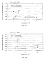
- FIG.7A shows a schematic circuitry of a main portion of a semiconductor integrated circuit device according to the second embodiment of the invention.
- the differential amplifier 18 is replaced with the circuitry of Fig.7A.
- Fig.7B is a plot showing an example of a bias current Ibias versus a sweep time. With respect to each portion of the second embodiment in Fig.2 is designated by the same reference numeral.
- the second embodiment differs from the first embodiment in that the difference between the maximum value and the minimum value of the oscillation output signal RFout is substantially equal to the threshold voltage of the MOSFET by the sweep of the control voltage Vbias.
- a comparison between the maximum voltage Vmax shifted by the first predetermined voltage Vref and the minimum voltage Vmin is carried out, and the bias current Ibias of the voltage controlled oscillation circuit 12 is regulated based on the result of the comparison.
- the phase noise performance is tuned because the difference between the maximum value and the minimum value of the oscillation output signal RFout is adjusted when the power supply voltage is initially provided or when it is needed.
- the comparator 60 compares the voltage Vmax-Vthn+
- the counter 63 is reset when the tuning signal TUNE is provided.
- the tuning signal TUNE is provided when the power supply voltage Vdd is initially provided or when it is needed. Then, the counter 63 starts to count the clock signal CLK when an enable signal ENABLE is high level.
- the D/A converter 64 converts the count value of the counter 63 to the analogue voltage.
- the analogue voltage is outputted to the bias current control circuit 17 as the control voltage Vbias.
- the control voltage Vbias is swept lineally from the power supply voltage vdd to the ground.
- the bias current Ibias is swept in accordance with the control voltage Vbias. Consequently, the difference between the maximum value and the minimum value of the oscillation output signal RFout is increasing.
- the output of the comparator 60 is inverted to low level and the enable signal ENABLE is low level. Then, the counter 63 stops to count the clock signal CLK.
- the differential amplifier 18 shown in Fig.2 is replaced with the comparator 60 and the bias current sweep circuit 61.
- the semiconductor integrated circuit device of the second embodiment can be used as the first and second semiconductor integrated circuit devices 46, 50.
- the semiconductor integrated circuit device in accordance with the second embodiment is capable of tuning the phase noise performance when it is needed. It is because the difference between the maximum value and the minimum value of the oscillation output signal RFout is substantially equal to the threshold voltage of the N-type MOSFET by the sweep of the control voltage Vbias.
- the semiconductor integrated circuit device of the second embodiment gives more flexibility to a design of a phase locked loop having the voltage controlled oscillation circuit.
- the semiconductor integrated circuit device of the second embodiment suits a design of being incorporated into a semiconductor digital integrated circuit device.
- FIG.8A shows a schematic circuitry of a main portion of a semiconductor integrated circuit device according to the third embodiment of the invention.
- the differential amplifier 18 is replaced with the circuit of Fig.8A.
- Fig.8B is a plot showing an example of a bias current versus a sweep time. With respect to each portion of the third embodiment in Fig.2 is designated by the same reference numeral.
- the third embodiment differs from the first embodiment in that the bias current control circuit 17 is provided with a parallel-connected circuit of a plurality of switching transistors.
- the bias current Ibias of the bias current control circuit 17 shown in Fig.1 is regulated by digital control, instead of analogue control.
- analogue circuit of the bias current control circuit 17 is replaced with the digital circuit which is more suitable for being incorporated into the semiconductor digital integrated circuit device.
- the semiconductor integrated circuit device of the third embodiment is provided with a bias current sweep circuit 71 and a bias current control circuit 73.
- the bias current sweep circuit 71 includes the AND circuit 62, the counter 63 and a decoder 70 to decode the count value of the counter 63.
- the decoded signal is provided to the bias current control circuit 73.
- the bias current control circuit 73 includes a plurality of the switching transistors 72.
- a plurality of gates G72 of the switching transistors 72 is connected to a plurality of the output terminals of the decoder 70 respectively.
- a plurality of sources S72 of the switching transistors 72 is connected to the power supply voltage vdd.
- a plurality of drains D72 of the switching transistors 72 is connected to the voltage controlled oscillation circuit 12.
- the counter 63 is reset when the tuning signal TUNE is provided.
- the tuning signal TUNE is provided when the power supply voltage Vdd is initially provided or when it is needed. Then, the counter 63 starts to count the clock signal CLK when an enable signal ENABLE is high level.
- the decoder 70 decodes the count value of the counter 63 to a plurality of switching signals.
- the plurality of the switching signals is provided to a plurality of the gates G72 of the switching transistors 72 respectively. Then, a plurality of the switching transistors 72 is turned on in accordance with the plurality of the switching signals.
- the bias current Ibias of the voltage controlled oscillation circuit 12 increases like the stairs.
- the difference between the maximum value and the minimum value of the oscillation output signal RFout also increases like the stairs.
- the output of the comparator 60 is inverted to low level and the enable signal ENABLE is low level. Then, the counter 63 stops to count the clock signal CLK.
- the difference between the maximum value and the minimum value of the oscillation output signal RFout is substantially equal to the threshold voltage of the N-type MOSFET. It is because the plurality of the switching transistors 72 is maintained to the turn-on condition when the counter 63 stopped the count of the clock signal CLK.
- the bias current sweep circuit 61 shown in Fig.7A is replaced with the bias current sweep circuit 71
- the bias current control circuit 17 shown in Fig.2 is replaced with the bias current control circuit 73.
- the semiconductor integrated circuit device of the third embodiment can be used as the first and second semiconductor integrated circuit devices 46, 50.
- FIG. 9 shows a schematic circuitry of a semiconductor integrated circuit device according to a fourth embodiment of the invention.
- Fig. 2 With respect to each portion of the fourth embodiment in Fig. 2 is designated by the same reference numeral.
- the difference between the maximum value and the minimum value of the oscillation output signal RFout is fixed to the threshold voltage Vthn of the N-type MOSEET that gives sufficient phase noise performance.
- the difference between the maximum value and the minimum value of the oscillation output signal RFout is varied by the change of the threshold voltage Vthn of the N-type MOSFET caused by a substrate bias effect.
- the threshold voltage control circuit is added to the semiconductor integrated circuit device shown in Fig.1.
- the threshold voltage control circuit changes the threshold voltage Vttin of the N-type MOSFET of the voltage controlled oscillation circuit 12.
- Both the difference between the maximum value and the minimum value of the oscillation output signal RFout being substantially equal to the changed threshold voltage of the N-type MOSFET of the voltage controlled oscillation circuit 12 and the sufficient phase noise performance are obtained.
- the threshold voltage control circuit is also applied to the second and third embodiments.
- the semiconductor integrated circuit device 80 of the forth embodiment is provided with a threshold voltage control circuit 84, a third reference voltage generation circuit 86 and a subtraction circuit 87.
- the threshold voltage control circuit 84 includes a eleventh N-type MOSFET M11 and a differential amplifier 83 having two input terminals and output terminal.
- a drain D11 of the eleventh MOSFET M11 is connected to the power supply voltage Vdd via a fourth constant current source 81, and a source S11 of the eleventh MOSFET M11 is connected to the ground.
- One of the input terminals of the differential amplifier 83 is connected to a gate G11 of the eleventh MOSFET M11, the other of the input terminals of the differential amplifier 83 is connected to a second reference voltage generation circuit 82 to generate a second predetermined voltage Vref2, and the output terminal of the differential amplifier 83 is connected to a back-gate B11 of the eleventh MOSFET M11, and to back-gates B11, B12 of the first and second MOSFET M1, M2 of the first amplification circuit 22.
- the third reference voltage generation circuit 86 includes a twelfth N-type MOSFET M12 which a source S12 of the twelfth MOSFET M12 is connected to the ground via a fifth constant current source 85, a drain D12 of the twelfth MOSFET M12 is connected to the power supply voltage Vdd, a gate G12 of the twelfth MOSFET M12 is connected to the node d of the minimum value detection circuit 14.
- the subtraction circuit 87 has two input terminals and output terminal. One of the input terminals is connected to the node e of the first reference voltage generation circuit 16 and the other input terminals is connected to a node g of the third reference voltage generation circuit 86.
- the threshold voltage of the eleventh MOSFET M11 is substantially equal to the threshold voltages of the first and second MOSF2Ts M1, M2.
- a voltage between the gate G11 and the source S11 of the eleventh MOSFET M11 is substantially equal to the threshold voltage Vthn of the eleventh MOSFET M11. It is because the MOSFET M11 is driven at a starting current by the fourth constant current source 81.
- the threshold voltage Vthn of the eleventh MOSFET M11 is substantially equal to the second predetermined voltage Vref2. It is because the voltage of the back-gate B11 is sifted so that the voltage of one of the input terminals of the differential amplifier 83 is substantially equal to the voltage of the other of the input terminals of the differential amplifier 83.
- the threshold voltages Vthn of the first and second MOSFETs M1, M2 are substantially equal to the second predetermined voltage Vref2. It is because the back-gates B1, B2 of the first and second MOSFETs M1, M2 of the first amplification circuit 22 are connected to the output terminal of the differential amplifier 83.
- One of the input terminals of the differential amplifier 18 is connected to the output terminal of the subtraction circuit 87.
- the difference between the maximum value and the minimum value of the oscillation output signal RFout is provided to one of the input terminals of the differential amplifier 18.
- the other of the input terminals of the differential amplifier18 is connected to the second reference voltage generation circuit 82.
- the second predetermined voltage Vref2 is provided to the other of the input terminals of the differential amplifier 18.
- the difference between the maximum value and the minimum value of the oscillation output signal RFout is substantially equal to the second predetermined voltage Vref2.
- the difference between the maximum value and the minimum value of the oscillation output signal RFout is varied so as to be substantially equal to the threshold voltage of the N-type MOSFET by the differential amplifier 18.
- the semiconductor integrated circuit device 80 can be used as the first and second semiconductor integrated circuit devices 46, 50.
- the semiconductor integrated circuit device 80 in accordance with the fourth embodiment has a merit that the difference between the maximum value and the value of the oscillation output signal RFout can be adapted to an external circuit for some purpose while maintaining the sufficient phase noise performance.
- the difference between the maximum value and the minimum value of the oscillation output signal RFout is substantially equal to the threshold voltage Vthn of the N-type MOSFET.
- the difference between the maximum value and the minimum value of the oscillation output signal RFout may be substantially equal to the threshold voltage
- FIG.10 shows a schematic circuitry of a semiconductor integrated circuit device according to another embodiment of the invention.
- FIG.2 With respect to each portion of the fourth embodiment in Fig.2 is designated by the same reference numeral.
- the ninth P-type MOSFET M9 of the first reference voltage generation circuit 16 is replaced with a thirteenth N-type MOSFET M13.
- the tenth P-type MOSFET M10 of the bias current control circuit 17 is replaced with a fourteenth N-type MOSFET M14.
- the bias current control circuit 17 is coupled between the voltage controlled oscillation circuit 12 and the ground.
- one of the input terminals of the differential amplifier 18 is connected to the node d of the first reference voltage generation circuit 16.
- the gate G13 of the thirteenth MOSFET M13 of the first reference voltage generation circuit 16 is connected to the node d of the minimum value detection circuit 14.
- the other of the input terminals of the differential amplifier 18 is connected to the node c of the maximum value detection circuit 13.
- the voltage controlled oscillation circuit 12 is provided with both the first amplification circuit 22 and the second amplification circuit 23. But the voltage controlled oscillation circuit 12 may be provided with one of the first amplification circuit 22 and the second amplification circuit 23.
- the transistor is the MOSFET. But the transistor may be a bipolar transistor.
Applications Claiming Priority (1)
| Application Number | Priority Date | Filing Date | Title |
|---|---|---|---|
| JP2004365787 | 2004-12-17 |
Publications (2)
| Publication Number | Publication Date |
|---|---|
| EP1672799A1 true EP1672799A1 (fr) | 2006-06-21 |
| EP1672799B1 EP1672799B1 (fr) | 2008-03-19 |
Family
ID=35929822
Family Applications (1)
| Application Number | Title | Priority Date | Filing Date |
|---|---|---|---|
| EP05027479A Expired - Fee Related EP1672799B1 (fr) | 2004-12-17 | 2005-12-15 | Dispositif de circuit intégré semiconducteur |
Country Status (3)
| Country | Link |
|---|---|
| US (1) | US7327201B2 (fr) |
| EP (1) | EP1672799B1 (fr) |
| DE (1) | DE602005005430T2 (fr) |
Families Citing this family (19)
| Publication number | Priority date | Publication date | Assignee | Title |
|---|---|---|---|---|
| TWI264875B (en) * | 2005-01-14 | 2006-10-21 | Ind Tech Res Inst | Voltage controlled oscillator capable of resisting supply voltage variation and/or process variation |
| EP1952214A1 (fr) | 2005-11-15 | 2008-08-06 | Freescale Semiconductor, Inc. | Dispositif et procede permettant de compenser des chutes de tension |
| JP2007251228A (ja) * | 2006-03-13 | 2007-09-27 | Toshiba Corp | 電圧制御発振器、動作電流調整装置、および、電圧制御発振器の動作電流調整方法 |
| US20080007361A1 (en) * | 2006-07-04 | 2008-01-10 | Mediatek Inc. | Oscillator with Voltage Drop Generator |
| DE102006032276B4 (de) * | 2006-07-12 | 2011-10-27 | Infineon Technologies Ag | Amplitudenregelungsschaltung |
| US7515009B2 (en) * | 2006-10-30 | 2009-04-07 | Ili Technology Corp. | Oscillating apparatus with adjustable oscillating frequency |
| US7830113B2 (en) * | 2006-11-28 | 2010-11-09 | Semiconductor Energy Laboratory Co., Ltd. | Semiconductor device, communication system, and method of charging the semiconductor device |
| US7983373B2 (en) * | 2007-02-07 | 2011-07-19 | Vintomie Networks B.V., Llc | Clock distribution for 10GBase-T analog front end |
| JP4908284B2 (ja) * | 2007-03-28 | 2012-04-04 | ルネサスエレクトロニクス株式会社 | 電圧制御発振器 |
| JP2008306331A (ja) * | 2007-06-06 | 2008-12-18 | Toshiba Corp | 半導体集積回路装置 |
| US7579920B1 (en) * | 2007-07-13 | 2009-08-25 | Rf Micro Devices, Inc. | Self-biasing low-phase noise LC oscillator |
| KR100903154B1 (ko) * | 2007-09-21 | 2009-06-17 | 한국전자통신연구원 | 캐스코드 증폭기 및 그를 이용한 차동 캐스코드 전압제어발진기 |
| JP2010045133A (ja) * | 2008-08-11 | 2010-02-25 | Toshiba Corp | 半導体集積回路装置 |
| JP4929306B2 (ja) * | 2009-03-17 | 2012-05-09 | 株式会社東芝 | バイアス生成回路及び電圧制御発振器 |
| US8159308B1 (en) * | 2009-04-20 | 2012-04-17 | Marvell International Ltd. | Low power voltage controlled oscillator (VCO) |
| JP2011155489A (ja) * | 2010-01-27 | 2011-08-11 | Toshiba Corp | 半導体集積回路装置および発振周波数較正方法 |
| US9473150B2 (en) * | 2013-11-22 | 2016-10-18 | Silicon Laboratories Inc. | Peak detectors for amplitude control of oscillators |
| US9531389B1 (en) * | 2014-09-15 | 2016-12-27 | Farbod Behbahani | Fractional-N synthesizer VCO coarse tuning |
| KR102642912B1 (ko) * | 2018-12-20 | 2024-03-04 | 삼성전기주식회사 | 차동 회로의 전류 제어 장치 |
Citations (2)
| Publication number | Priority date | Publication date | Assignee | Title |
|---|---|---|---|---|
| EP0978945A1 (fr) * | 1998-08-04 | 2000-02-09 | Zentrum Mikroelektronik Dresden GmbH | Méthode de génération d'une tension alternative à fréquence stabilisée par quartz et oscillateur amplificateur Pierce mettant en oeuvre ladite méthode |
| US6653908B1 (en) * | 2001-10-18 | 2003-11-25 | National Semiconductor Corporation | Oscillator circuit with automatic level control for selectively minimizing phase noise |
Family Cites Families (3)
| Publication number | Priority date | Publication date | Assignee | Title |
|---|---|---|---|---|
| US5834983A (en) * | 1997-09-30 | 1998-11-10 | Hewlett-Packard Company | Wideband oscillator with automatic bias control |
| US6700450B2 (en) * | 2002-07-29 | 2004-03-02 | Cognio, Inc. | Voltage-controlled oscillator with an automatic amplitude control circuit |
| US7061337B2 (en) * | 2004-07-14 | 2006-06-13 | Infineon Technologies Ag | Amplitude control circuit |
-
2005
- 2005-12-15 US US11/300,367 patent/US7327201B2/en not_active Expired - Fee Related
- 2005-12-15 DE DE602005005430T patent/DE602005005430T2/de active Active
- 2005-12-15 EP EP05027479A patent/EP1672799B1/fr not_active Expired - Fee Related
Patent Citations (2)
| Publication number | Priority date | Publication date | Assignee | Title |
|---|---|---|---|---|
| EP0978945A1 (fr) * | 1998-08-04 | 2000-02-09 | Zentrum Mikroelektronik Dresden GmbH | Méthode de génération d'une tension alternative à fréquence stabilisée par quartz et oscillateur amplificateur Pierce mettant en oeuvre ladite méthode |
| US6653908B1 (en) * | 2001-10-18 | 2003-11-25 | National Semiconductor Corporation | Oscillator circuit with automatic level control for selectively minimizing phase noise |
Non-Patent Citations (2)
| Title |
|---|
| AXEL D. BERNY ET AL.: "A 1.8 GHz LC VCO with 1.3 GHz Tuning Range and Mixed-signal Amplitude Calibration", 2004 SYMPOSIUM ON VLSI CIRCUITS, 2004. DIGEST OF TECHNICAL PAPERS, 17 June 2004 (2004-06-17) - 19 June 2004 (2004-06-19), pages 54-57, XP002371693 * |
| MIYASHITA DAISUKE ET AL.: "A Phase Noise Minimization of CMOS VCOs over Wide Tuning Range and Large PVT Variations", PROCEEDINGS OF THE IEEE 2005 CUSTOM INTEGRATED CIRCUITS CONFERENCE, 2005, SAN JOSE, CA, USA, 18 September 2005 (2005-09-18), Piscataway, NJ, USA, IEEE, pages 583 - 586, XP010873594 * |
Also Published As
| Publication number | Publication date |
|---|---|
| DE602005005430D1 (de) | 2008-04-30 |
| US20060152295A1 (en) | 2006-07-13 |
| EP1672799B1 (fr) | 2008-03-19 |
| DE602005005430T2 (de) | 2009-05-14 |
| US7327201B2 (en) | 2008-02-05 |
Similar Documents
| Publication | Publication Date | Title |
|---|---|---|
| EP1672799A1 (fr) | Dispositif de circuit intégré semi-conducteur et appareil de communication sans fil | |
| US7279998B2 (en) | Voltage-controlled oscillator | |
| US20070262825A1 (en) | Embedded structure circuit for VCO and regulator | |
| US20050190002A1 (en) | Voltage-controlled oscillator, radio communication apparatus and voltage-controlled oscillation method | |
| US20020093385A1 (en) | Oscillation circuit with voltage-controlled oscillators | |
| JP4922609B2 (ja) | 半導体集積回路装置およびそれを用いた無線通信装置 | |
| US20060255865A1 (en) | Differential switches for voltage controlled oscillator coarse tuning | |
| US20090033428A1 (en) | Voltage controlled oscillator | |
| JP4992903B2 (ja) | 局部発振器とこれを用いた受信装置及び電子機器 | |
| US6853262B2 (en) | Voltage-controlled oscillator circuit which compensates for supply voltage fluctuations | |
| US8222963B2 (en) | Voltage-controlled oscillator | |
| US20080211592A1 (en) | Drive Circuit for a Voltage Controlled Differential Oscillator | |
| US6927643B2 (en) | Oscillator topology for very low phase noise operation | |
| US20100093303A1 (en) | Circuit current generation apparatus and method thereof, and signal processing apparatus | |
| US20080315964A1 (en) | Voltage controlled oscillator using tunable active inductor | |
| US7126435B2 (en) | Voltage controlled oscillator amplitude control circuit | |
| US11258403B2 (en) | Voltage controlled oscillator, semiconductor integrated circuit, and transmission and reception device | |
| US7944318B2 (en) | Voltage controlled oscillator, and PLL circuit and radio communication device each including the same | |
| US4853655A (en) | High frequency CMOS oscillator | |
| US7012487B2 (en) | Transconductance device employing native MOS transistors | |
| EP0318320B1 (fr) | Oscillateur électronique | |
| CN110875738B (zh) | 晶体振荡器控制电路以及相关的振荡器装置 | |
| JP4228758B2 (ja) | 圧電発振器 | |
| JP2005333466A (ja) | 電圧制御発振器、並びにこれを用いた無線通信装置 | |
| JP2006101135A (ja) | 電圧制御発振回路およびそれを用いた半導体集積装置、無線通信装置 |
Legal Events
| Date | Code | Title | Description |
|---|---|---|---|
| PUAI | Public reference made under article 153(3) epc to a published international application that has entered the european phase |
Free format text: ORIGINAL CODE: 0009012 |
|
| 17P | Request for examination filed |
Effective date: 20051215 |
|
| AK | Designated contracting states |
Kind code of ref document: A1 Designated state(s): AT BE BG CH CY CZ DE DK EE ES FI FR GB GR HU IE IS IT LI LT LU LV MC NL PL PT RO SE SI SK TR |
|
| AX | Request for extension of the european patent |
Extension state: AL BA HR MK YU |
|
| 17Q | First examination report despatched |
Effective date: 20060915 |
|
| AKX | Designation fees paid |
Designated state(s): DE FR GB |
|
| 17Q | First examination report despatched |
Effective date: 20060915 |
|
| GRAP | Despatch of communication of intention to grant a patent |
Free format text: ORIGINAL CODE: EPIDOSNIGR1 |
|
| RTI1 | Title (correction) |
Free format text: SEMICONDUCTOR INTEGRATED CIRCUIT DEVICE |
|
| GRAS | Grant fee paid |
Free format text: ORIGINAL CODE: EPIDOSNIGR3 |
|
| GRAA | (expected) grant |
Free format text: ORIGINAL CODE: 0009210 |
|
| AK | Designated contracting states |
Kind code of ref document: B1 Designated state(s): DE FR GB |
|
| REG | Reference to a national code |
Ref country code: GB Ref legal event code: FG4D |
|
| REF | Corresponds to: |
Ref document number: 602005005430 Country of ref document: DE Date of ref document: 20080430 Kind code of ref document: P |
|
| ET | Fr: translation filed | ||
| PLBE | No opposition filed within time limit |
Free format text: ORIGINAL CODE: 0009261 |
|
| STAA | Information on the status of an ep patent application or granted ep patent |
Free format text: STATUS: NO OPPOSITION FILED WITHIN TIME LIMIT |
|
| 26N | No opposition filed |
Effective date: 20081222 |
|
| REG | Reference to a national code |
Ref country code: FR Ref legal event code: PLFP Year of fee payment: 11 |
|
| PGFP | Annual fee paid to national office [announced via postgrant information from national office to epo] |
Ref country code: DE Payment date: 20151208 Year of fee payment: 11 Ref country code: GB Payment date: 20151209 Year of fee payment: 11 |
|
| PGFP | Annual fee paid to national office [announced via postgrant information from national office to epo] |
Ref country code: FR Payment date: 20151110 Year of fee payment: 11 |
|
| REG | Reference to a national code |
Ref country code: DE Ref legal event code: R119 Ref document number: 602005005430 Country of ref document: DE |
|
| GBPC | Gb: european patent ceased through non-payment of renewal fee |
Effective date: 20161215 |
|
| REG | Reference to a national code |
Ref country code: FR Ref legal event code: ST Effective date: 20170831 |
|
| PG25 | Lapsed in a contracting state [announced via postgrant information from national office to epo] |
Ref country code: FR Free format text: LAPSE BECAUSE OF NON-PAYMENT OF DUE FEES Effective date: 20170102 |
|
| PG25 | Lapsed in a contracting state [announced via postgrant information from national office to epo] |
Ref country code: GB Free format text: LAPSE BECAUSE OF NON-PAYMENT OF DUE FEES Effective date: 20161215 Ref country code: DE Free format text: LAPSE BECAUSE OF NON-PAYMENT OF DUE FEES Effective date: 20170701 |