EP1672371A1 - A bearing assembly for the hub of a motor vehicle wheel with a sealing device and a device for detecting rotation - Google Patents
A bearing assembly for the hub of a motor vehicle wheel with a sealing device and a device for detecting rotation Download PDFInfo
- Publication number
- EP1672371A1 EP1672371A1 EP05102503A EP05102503A EP1672371A1 EP 1672371 A1 EP1672371 A1 EP 1672371A1 EP 05102503 A EP05102503 A EP 05102503A EP 05102503 A EP05102503 A EP 05102503A EP 1672371 A1 EP1672371 A1 EP 1672371A1
- Authority
- EP
- European Patent Office
- Prior art keywords
- cylindrical
- bearing assembly
- race
- insert
- phonic wheel
- Prior art date
- Legal status (The legal status is an assumption and is not a legal conclusion. Google has not performed a legal analysis and makes no representation as to the accuracy of the status listed.)
- Withdrawn
Links
Images
Classifications
-
- F—MECHANICAL ENGINEERING; LIGHTING; HEATING; WEAPONS; BLASTING
- F16—ENGINEERING ELEMENTS AND UNITS; GENERAL MEASURES FOR PRODUCING AND MAINTAINING EFFECTIVE FUNCTIONING OF MACHINES OR INSTALLATIONS; THERMAL INSULATION IN GENERAL
- F16C—SHAFTS; FLEXIBLE SHAFTS; ELEMENTS OR CRANKSHAFT MECHANISMS; ROTARY BODIES OTHER THAN GEARING ELEMENTS; BEARINGS
- F16C19/00—Bearings with rolling contact, for exclusively rotary movement
- F16C19/02—Bearings with rolling contact, for exclusively rotary movement with bearing balls essentially of the same size in one or more circular rows
- F16C19/14—Bearings with rolling contact, for exclusively rotary movement with bearing balls essentially of the same size in one or more circular rows for both radial and axial load
- F16C19/18—Bearings with rolling contact, for exclusively rotary movement with bearing balls essentially of the same size in one or more circular rows for both radial and axial load with two or more rows of balls
- F16C19/181—Bearings with rolling contact, for exclusively rotary movement with bearing balls essentially of the same size in one or more circular rows for both radial and axial load with two or more rows of balls with angular contact
- F16C19/183—Bearings with rolling contact, for exclusively rotary movement with bearing balls essentially of the same size in one or more circular rows for both radial and axial load with two or more rows of balls with angular contact with two rows at opposite angles
- F16C19/184—Bearings with rolling contact, for exclusively rotary movement with bearing balls essentially of the same size in one or more circular rows for both radial and axial load with two or more rows of balls with angular contact with two rows at opposite angles in O-arrangement
- F16C19/185—Bearings with rolling contact, for exclusively rotary movement with bearing balls essentially of the same size in one or more circular rows for both radial and axial load with two or more rows of balls with angular contact with two rows at opposite angles in O-arrangement with two raceways provided integrally on a part other than a race ring, e.g. a shaft or housing
-
- B—PERFORMING OPERATIONS; TRANSPORTING
- B60—VEHICLES IN GENERAL
- B60B—VEHICLE WHEELS; CASTORS; AXLES FOR WHEELS OR CASTORS; INCREASING WHEEL ADHESION
- B60B27/00—Hubs
- B60B27/0005—Hubs with ball bearings
-
- B—PERFORMING OPERATIONS; TRANSPORTING
- B60—VEHICLES IN GENERAL
- B60B—VEHICLE WHEELS; CASTORS; AXLES FOR WHEELS OR CASTORS; INCREASING WHEEL ADHESION
- B60B27/00—Hubs
- B60B27/0073—Hubs characterised by sealing means
-
- B—PERFORMING OPERATIONS; TRANSPORTING
- B60—VEHICLES IN GENERAL
- B60B—VEHICLE WHEELS; CASTORS; AXLES FOR WHEELS OR CASTORS; INCREASING WHEEL ADHESION
- B60B27/00—Hubs
- B60B27/0078—Hubs characterised by the fixation of bearings
- B60B27/0084—Hubs characterised by the fixation of bearings caulking to fix inner race
-
- B—PERFORMING OPERATIONS; TRANSPORTING
- B60—VEHICLES IN GENERAL
- B60B—VEHICLE WHEELS; CASTORS; AXLES FOR WHEELS OR CASTORS; INCREASING WHEEL ADHESION
- B60B27/00—Hubs
- B60B27/02—Hubs adapted to be rotatably arranged on axle
-
- F—MECHANICAL ENGINEERING; LIGHTING; HEATING; WEAPONS; BLASTING
- F16—ENGINEERING ELEMENTS AND UNITS; GENERAL MEASURES FOR PRODUCING AND MAINTAINING EFFECTIVE FUNCTIONING OF MACHINES OR INSTALLATIONS; THERMAL INSULATION IN GENERAL
- F16C—SHAFTS; FLEXIBLE SHAFTS; ELEMENTS OR CRANKSHAFT MECHANISMS; ROTARY BODIES OTHER THAN GEARING ELEMENTS; BEARINGS
- F16C33/00—Parts of bearings; Special methods for making bearings or parts thereof
- F16C33/72—Sealings
- F16C33/76—Sealings of ball or roller bearings
- F16C33/78—Sealings of ball or roller bearings with a diaphragm, disc, or ring, with or without resilient members
- F16C33/7886—Sealings of ball or roller bearings with a diaphragm, disc, or ring, with or without resilient members mounted outside the gap between the inner and outer races, e.g. sealing rings mounted to an end face or outer surface of a race
-
- F—MECHANICAL ENGINEERING; LIGHTING; HEATING; WEAPONS; BLASTING
- F16—ENGINEERING ELEMENTS AND UNITS; GENERAL MEASURES FOR PRODUCING AND MAINTAINING EFFECTIVE FUNCTIONING OF MACHINES OR INSTALLATIONS; THERMAL INSULATION IN GENERAL
- F16C—SHAFTS; FLEXIBLE SHAFTS; ELEMENTS OR CRANKSHAFT MECHANISMS; ROTARY BODIES OTHER THAN GEARING ELEMENTS; BEARINGS
- F16C41/00—Other accessories, e.g. devices integrated in the bearing not relating to the bearing function as such
- F16C41/007—Encoders, e.g. parts with a plurality of alternating magnetic poles
-
- F—MECHANICAL ENGINEERING; LIGHTING; HEATING; WEAPONS; BLASTING
- F16—ENGINEERING ELEMENTS AND UNITS; GENERAL MEASURES FOR PRODUCING AND MAINTAINING EFFECTIVE FUNCTIONING OF MACHINES OR INSTALLATIONS; THERMAL INSULATION IN GENERAL
- F16J—PISTONS; CYLINDERS; SEALINGS
- F16J15/00—Sealings
- F16J15/16—Sealings between relatively-moving surfaces
- F16J15/32—Sealings between relatively-moving surfaces with elastic sealings, e.g. O-rings
- F16J15/3248—Sealings between relatively-moving surfaces with elastic sealings, e.g. O-rings provided with casings or supports
- F16J15/3252—Sealings between relatively-moving surfaces with elastic sealings, e.g. O-rings provided with casings or supports with rigid casings or supports
-
- G—PHYSICS
- G01—MEASURING; TESTING
- G01P—MEASURING LINEAR OR ANGULAR SPEED, ACCELERATION, DECELERATION, OR SHOCK; INDICATING PRESENCE, ABSENCE, OR DIRECTION, OF MOVEMENT
- G01P3/00—Measuring linear or angular speed; Measuring differences of linear or angular speeds
- G01P3/42—Devices characterised by the use of electric or magnetic means
- G01P3/44—Devices characterised by the use of electric or magnetic means for measuring angular speed
- G01P3/443—Devices characterised by the use of electric or magnetic means for measuring angular speed mounted in bearings
-
- G—PHYSICS
- G01—MEASURING; TESTING
- G01P—MEASURING LINEAR OR ANGULAR SPEED, ACCELERATION, DECELERATION, OR SHOCK; INDICATING PRESENCE, ABSENCE, OR DIRECTION, OF MOVEMENT
- G01P3/00—Measuring linear or angular speed; Measuring differences of linear or angular speeds
- G01P3/42—Devices characterised by the use of electric or magnetic means
- G01P3/44—Devices characterised by the use of electric or magnetic means for measuring angular speed
- G01P3/48—Devices characterised by the use of electric or magnetic means for measuring angular speed by measuring frequency of generated current or voltage
- G01P3/481—Devices characterised by the use of electric or magnetic means for measuring angular speed by measuring frequency of generated current or voltage of pulse signals
- G01P3/487—Devices characterised by the use of electric or magnetic means for measuring angular speed by measuring frequency of generated current or voltage of pulse signals delivered by rotating magnets
-
- F—MECHANICAL ENGINEERING; LIGHTING; HEATING; WEAPONS; BLASTING
- F16—ENGINEERING ELEMENTS AND UNITS; GENERAL MEASURES FOR PRODUCING AND MAINTAINING EFFECTIVE FUNCTIONING OF MACHINES OR INSTALLATIONS; THERMAL INSULATION IN GENERAL
- F16C—SHAFTS; FLEXIBLE SHAFTS; ELEMENTS OR CRANKSHAFT MECHANISMS; ROTARY BODIES OTHER THAN GEARING ELEMENTS; BEARINGS
- F16C2326/00—Articles relating to transporting
- F16C2326/01—Parts of vehicles in general
- F16C2326/02—Wheel hubs or castors
Definitions
- the present invention refers to a bearing assembly for the hub of a motor vehicle wheel with a sealing device and a device for detecting rotational speed.
- bearing assemblies which comprise a bearing unit with a rotatable outer race, a stationary inner race, sealing devices mounted at the sides of the bearing for sealing the gap between the races, and a phonic wheel or encoder being part of a device for sensing relative rotation between the races of the bearing unit.
- the phonic wheel is a cylindrical annular element of magnetised plastic or rubber which is fixed co-axially to the outside of a metallic insert of substantially cylindrical shape forcedly fitted around the outer rotating race of the bearing.
- the lateral sealing devices each comprise a flexible annular gasket vulcanized onto a respective metallic annular insert fixed to the rotating race or the stationary race. The gasket forms one or more sealing lips adapted to slide against an opposite surface secured to the other race (stationary or rotating).
- the force fit of the shield supporting the phonic wheel inevitably deforms and sometimes breaks the phonic wheel, thereby impairing operation of the rotation detecting device.
- a bearing unit for the hub of a motor vehicle wheel comprises a radially outer rotatable race 10, radially inner stationary races 11, and rolling bodies 12, in this example balls, interposed between the races 10 and 11.
- the bearing unit is equipped with a device for sensing the rotational speed of the outer race 10 relatively to the inner race 11.
- This device includes a phonic wheel or encoder 13, mounted onto the rotating race 10, and a sensor (not shown) facing the phonic wheel 13 and mounted onto a fixed part of the vehicle.
- the phonic wheel 13 is an annular cylindrical element of plastic or rubber magnetized with polarities alternating in a circumferential direction, co-moulded or vulcanized onto a metallic insert 14 of generally annular shape, forcedly fitted onto the outer race 10.
- the insert 14 is suitably shaped so as to also form an extension acting as a support for a gasket of a sealing device of the bearing, as described in the following.
- the insert 14 forms a first, radially outer, cylindrical axial portion 14a around which the phonic wheel 13 is co-moulded or vulcanized. Adjacent to the portion 14a supporting the phonic wheel 13, the insert 14 forms a second axial cylindrical portion 14b having a smaller diameter than that of the first cylindrical portion 14a. This second cylindrical portion 14b is forcedly fitted with radial interference onto a cylindrical outer surface 10b of the race 10.
- the first cylindrical portion 14a has an inner diameter slightly greater than the outer diameter of the race 10 at a zone 10a of the latter surrounded by the phonic wheel 13, so as to define a narrow cylindrical gap 16 or at least some radial play between the outer race 10 and the cylindrical portion 14a supporting the phonic wheel 13.
- the first cylindrical portion 14a of the insert 14 is supported projecting around the portion 10a of the race 10 by means of a radial portion 14c, connecting the cylindrical portions 14a and 14b, and abutting axially against a step or radial shoulder 10c which joins the cylindrical surfaces 10a and 10b.
- the second cylindrical portion 14b is joined to a radial wall 14d adapted for abutting against a side surface 10d of the outer race 10.
- the radial wall 14d is prolonged forming a radial flange 14e which extends in a radially inner direction towards the inner stationary race 11.
- a body 15 of rubber or elastomeric material is co-moulded or vulcanized on the radial flange 14e.
- the body 15 forms a radially inner portion 15a performing essentially sealing action by sliding against a stationary surface 11a secured to or integral with the inner race 11.
- the rubber body 15 forms integrally also a coating layer 15b that extends to cover the phonic wheel 13 on the outside in order to protect it from mud and crashes of stones and other objects coming from the near wheel.
- the coating layer 15b further cooperates to lock the phonic wheel 13 steadily on the supporting insert 14, and dispenses from applying a layer of adhesive between the insert 14 and the phonic wheel 13 in case the latter is made of plastoferrite.
- the coating layer 15b implies a further advantage during the magnetizing step of the phonic wheel, after this has been coupled to the insert 14: owing to its elasticity, the layer 15b adapts itself to the shape of the seat of the tool in which the phonic wheel to be magnetized is inserted, and therefore guarantees a correct positioning of the phonic wheel in the magnetizing apparatus also in those cases where the phonic wheel is not perfectly circular.
- a single metallic insert 14 supports both the phonic wheel 13 and the rubber body 15 that forms the sealing gasket. Having to handle and mount a single metallic insert instead of two, assembling operations are simplified as compared to prior art, since one supporting insert is eliminated, and, furthermore, only one special apparatus is required for mounting the single insert 14. Due to the particular shape of the insert 14, its force fitting onto the outer race 10 does not affect the coupling between the insert 14 and the phonic wheel 13, since neither cracks nor appreciable deformation are caused in the phonic wheel. Strain deriving from the force fitting is entirely absorbed by the portion 14b of the insert 14.
Landscapes
- Engineering & Computer Science (AREA)
- Mechanical Engineering (AREA)
- General Engineering & Computer Science (AREA)
- Physics & Mathematics (AREA)
- General Physics & Mathematics (AREA)
- Rolling Contact Bearings (AREA)
Abstract
The bearing assembly includes an outer rotatable race (10), one or two inner stationary races (11), an annular sealing gasket (15a) mounted laterally between the outer and inner races, and a phonic wheel (13) of magnetized plastic or rubber having an annular cylindrical shape mounted co-axially around an outer cylindrical surface (10a) of the outer race (10). The sealing gasket (15a) and the phonic wheel are both supported by a single metallic annular insert (14). The insert (14) forms a first cylindrical portion (14a) on which the phonic wheel (13) is co-moulded or vulcanized, a second cylindrical portion (14b) forcedly mounted against a second cylindrical surface (10b) of the outer race (10), and a flange (14e) on which the sealing gasket (15a) is vulcanized.
Description
- The present invention refers to a bearing assembly for the hub of a motor vehicle wheel with a sealing device and a device for detecting rotational speed.
- There are known bearing assemblies which comprise a bearing unit with a rotatable outer race, a stationary inner race, sealing devices mounted at the sides of the bearing for sealing the gap between the races, and a phonic wheel or encoder being part of a device for sensing relative rotation between the races of the bearing unit. The phonic wheel is a cylindrical annular element of magnetised plastic or rubber which is fixed co-axially to the outside of a metallic insert of substantially cylindrical shape forcedly fitted around the outer rotating race of the bearing. The lateral sealing devices each comprise a flexible annular gasket vulcanized onto a respective metallic annular insert fixed to the rotating race or the stationary race. The gasket forms one or more sealing lips adapted to slide against an opposite surface secured to the other race (stationary or rotating).
- The force fit of the shield supporting the phonic wheel inevitably deforms and sometimes breaks the phonic wheel, thereby impairing operation of the rotation detecting device.
- An object of the present invention is to provide a bearing assembly in which the above-mentioned drawback is eliminated. Another object of the invention is to simplify mounting the phonic wheel and the sealing devices onto the bearing unit.
- These and other objects and advantages, which will be more clearly understood herein after, are fulfilled according to the invention by a bearing assembly as defined in the appended claims.
- A description will now be given of the constructional and functional features of a few preferred but not-limiting embodiments of the invention; reference is made to the accompanying drawings, in which:
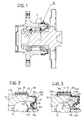
- figure 1 is axial cross-sectional view of a first embodiment of a bearing assembly according to the invention;
- figure 2 is an enlarged view of a detail indicated II in figure 1 and;
- figure 3 is a view similar to that of figure 2, showing a second embodiment of the invention.
- Referring initially to figures 1 and 2, a bearing unit for the hub of a motor vehicle wheel comprises a radially outer
rotatable race 10, radially innerstationary races 11, androlling bodies 12, in this example balls, interposed between theraces - The bearing unit is equipped with a device for sensing the rotational speed of the
outer race 10 relatively to theinner race 11. This device includes a phonic wheel orencoder 13, mounted onto therotating race 10, and a sensor (not shown) facing thephonic wheel 13 and mounted onto a fixed part of the vehicle. - The
phonic wheel 13 is an annular cylindrical element of plastic or rubber magnetized with polarities alternating in a circumferential direction, co-moulded or vulcanized onto ametallic insert 14 of generally annular shape, forcedly fitted onto theouter race 10. Theinsert 14 is suitably shaped so as to also form an extension acting as a support for a gasket of a sealing device of the bearing, as described in the following. - The
insert 14 forms a first, radially outer, cylindricalaxial portion 14a around which thephonic wheel 13 is co-moulded or vulcanized. Adjacent to theportion 14a supporting thephonic wheel 13, theinsert 14 forms a second axialcylindrical portion 14b having a smaller diameter than that of the firstcylindrical portion 14a. This secondcylindrical portion 14b is forcedly fitted with radial interference onto a cylindricalouter surface 10b of therace 10. The firstcylindrical portion 14a has an inner diameter slightly greater than the outer diameter of therace 10 at azone 10a of the latter surrounded by thephonic wheel 13, so as to define a narrowcylindrical gap 16 or at least some radial play between theouter race 10 and thecylindrical portion 14a supporting thephonic wheel 13. As shown in figure 2, the firstcylindrical portion 14a of theinsert 14 is supported projecting around theportion 10a of therace 10 by means of aradial portion 14c, connecting thecylindrical portions radial shoulder 10c which joins thecylindrical surfaces - The second
cylindrical portion 14b is joined to aradial wall 14d adapted for abutting against a side surface 10d of theouter race 10. Theradial wall 14d is prolonged forming aradial flange 14e which extends in a radially inner direction towards the innerstationary race 11. Abody 15 of rubber or elastomeric material is co-moulded or vulcanized on theradial flange 14e. - The
body 15 forms a radiallyinner portion 15a performing essentially sealing action by sliding against astationary surface 11a secured to or integral with theinner race 11. - In accordance with the alternative embodiment shown in figure 3, the
rubber body 15 forms integrally also acoating layer 15b that extends to cover thephonic wheel 13 on the outside in order to protect it from mud and crashes of stones and other objects coming from the near wheel. Thecoating layer 15b further cooperates to lock thephonic wheel 13 steadily on the supportinginsert 14, and dispenses from applying a layer of adhesive between theinsert 14 and thephonic wheel 13 in case the latter is made of plastoferrite. Thecoating layer 15b implies a further advantage during the magnetizing step of the phonic wheel, after this has been coupled to the insert 14: owing to its elasticity, thelayer 15b adapts itself to the shape of the seat of the tool in which the phonic wheel to be magnetized is inserted, and therefore guarantees a correct positioning of the phonic wheel in the magnetizing apparatus also in those cases where the phonic wheel is not perfectly circular. - As will be appreciated, a single
metallic insert 14 supports both thephonic wheel 13 and therubber body 15 that forms the sealing gasket. Having to handle and mount a single metallic insert instead of two, assembling operations are simplified as compared to prior art, since one supporting insert is eliminated, and, furthermore, only one special apparatus is required for mounting thesingle insert 14. Due to the particular shape of theinsert 14, its force fitting onto theouter race 10 does not affect the coupling between theinsert 14 and thephonic wheel 13, since neither cracks nor appreciable deformation are caused in the phonic wheel. Strain deriving from the force fitting is entirely absorbed by theportion 14b of theinsert 14. - It is to be understood that the invention is not limited to the embodiments described and illustrated here, which are to be regarded as exemplary embodiments of the invention. The invention is instead capable of modification with respect to shape, arrangement of parts, constructional and functional details. For example, those skilled in the art will recognize that the
counterface surface 11a against which the lips of thegasket 15a slide, could be replaced by a conventional annular metallic shield (known as "flinger") having a substantially L-shaped transversal cross-section.
Claims (7)
- A bearing assembly for the hub of a motor vehicle wheel, including:- a radially outer rotatable race (10);- at least one radially inner stationary race (11);- at least one annular sealing gasket (15a) of elastic material mounted laterally between the outer and inner races;- first supporting means for fixing the gasket (15) to the rotatable outer race (10);- a phonic wheel (13) of magnetized plastic or rubber having a substantially annular cylindrical shape mounted co-axially around a first cylindrical outer surface (10a) of the outer race (10);- second supporting means for fixing the phonic wheel (13) to the outer race (10);characterized in that said first and second supporting means are formed integrally by a single metallic annular insert (14) having- a first, radially outer cylindrical portion (14a) on which the phonic wheel (13) is co-moulded or vulcanized;- a second cylindrical portion (14b) forcedly mounted against a second cylindrical surface (10b) of the outer race (10) ;- a further flange portion (14e) extending in a radially inner direction towards the inner stationary race (11), on which flange portion (14e) there is co-moulded or vulcanized a body of rubber or elastomeric material (15) forming said annular gasket (15a) adapted to slide on a surface (11a) fixed to or integral with the stationary race (11).
- A bearing assembly according to claim 1, characterized in that the first cylindrical portion (14a) of the insert (14) is fitted around the first cylindrical surface (10a) of the outer race (10) in such manner as to form with this surface a cylindrical gap (16) or a predetermined radial play.
- A bearing assembly according to claim 1, characterized in that the first (14a) and the second (14b) cylindrical portions of the insert (14) are axially adjacent.
- A bearing assembly according to claim 3, characterized in that the first (14a) and the second (14b) cylindrical portions of the insert (14) are joined by a radial connecting portion (14c).
- A bearing assembly according to claims 2 and 4, characterized in that the radial connecting portion (14c) supports the first (14a) cylindrical portion of the insert (14) projecting around the first cylindrical surface (10a) of the outer race (10).
- A bearing assembly according to claim 3, characterized in that the radial connecting portion (14c) abuts axially against a shoulder (10c) formed by the outer race (10) between the first (10a) and the second (10b) cylindrical surfaces.
- A bearing assembly according to claim 1, characterized in that the body (15) of a rubber or elastomeric material further forms a coating layer (15b) covering the phonic wheel (13) from the outside.
Applications Claiming Priority (1)
| Application Number | Priority Date | Filing Date | Title |
|---|---|---|---|
| IT000889A ITTO20040889A1 (en) | 2004-12-20 | 2004-12-20 | BEARING GROUP FOR THE HUB OF THE WHEEL OF A VEHICLE WITH A SEALING DEVICE AND A DEVICE FOR DETECTION OF THE ROTATION |
Publications (1)
| Publication Number | Publication Date |
|---|---|
| EP1672371A1 true EP1672371A1 (en) | 2006-06-21 |
Family
ID=35149113
Family Applications (1)
| Application Number | Title | Priority Date | Filing Date |
|---|---|---|---|
| EP05102503A Withdrawn EP1672371A1 (en) | 2004-12-20 | 2005-03-30 | A bearing assembly for the hub of a motor vehicle wheel with a sealing device and a device for detecting rotation |
Country Status (2)
| Country | Link |
|---|---|
| EP (1) | EP1672371A1 (en) |
| IT (1) | ITTO20040889A1 (en) |
Cited By (3)
| Publication number | Priority date | Publication date | Assignee | Title |
|---|---|---|---|---|
| EP2090793A1 (en) * | 2008-02-14 | 2009-08-19 | SNR Roulements | Roller bearing with differential rigidity of zones instrumented by deformation |
| JP2017106514A (en) * | 2015-12-08 | 2017-06-15 | 内山工業株式会社 | Sealing device |
| US11326646B2 (en) | 2018-11-09 | 2022-05-10 | Aktiebolaget Skf | Detection device for wheel hub assembly |
Families Citing this family (2)
| Publication number | Priority date | Publication date | Assignee | Title |
|---|---|---|---|---|
| DE102019219176A1 (en) * | 2018-12-26 | 2020-07-02 | Aktiebolaget Skf | Wheel hub arrangement equipped with an innovative deflector |
| US11994166B2 (en) * | 2019-09-13 | 2024-05-28 | Nok Corporation | Sealing device |
Citations (2)
| Publication number | Priority date | Publication date | Assignee | Title |
|---|---|---|---|---|
| US5476272A (en) * | 1994-01-19 | 1995-12-19 | Federal-Mogul Corporation | Speed sensor ring for vehicle anti-lock brake system |
| US20040108849A1 (en) * | 2002-08-12 | 2004-06-10 | Makoto Muramatsu | Arrangement for mounting rotation speed sensor to wheel bearing assembly |
-
2004
- 2004-12-20 IT IT000889A patent/ITTO20040889A1/en unknown
-
2005
- 2005-03-30 EP EP05102503A patent/EP1672371A1/en not_active Withdrawn
Patent Citations (2)
| Publication number | Priority date | Publication date | Assignee | Title |
|---|---|---|---|---|
| US5476272A (en) * | 1994-01-19 | 1995-12-19 | Federal-Mogul Corporation | Speed sensor ring for vehicle anti-lock brake system |
| US20040108849A1 (en) * | 2002-08-12 | 2004-06-10 | Makoto Muramatsu | Arrangement for mounting rotation speed sensor to wheel bearing assembly |
Cited By (6)
| Publication number | Priority date | Publication date | Assignee | Title |
|---|---|---|---|---|
| EP2090793A1 (en) * | 2008-02-14 | 2009-08-19 | SNR Roulements | Roller bearing with differential rigidity of zones instrumented by deformation |
| FR2927678A1 (en) * | 2008-02-14 | 2009-08-21 | Snr Roulements Sa | BEARING BEARING WITH DIFFERENTIAL RIGIDITY OF DEFORMED INSTRUMENT ZONES |
| US8308369B2 (en) | 2008-02-14 | 2012-11-13 | Snr Roulements | Roller bearing with differential rigidity in the instrumented areas in deformation |
| JP2017106514A (en) * | 2015-12-08 | 2017-06-15 | 内山工業株式会社 | Sealing device |
| US11326646B2 (en) | 2018-11-09 | 2022-05-10 | Aktiebolaget Skf | Detection device for wheel hub assembly |
| US11530722B2 (en) | 2018-11-09 | 2022-12-20 | Aktiebolaget Skf | Detection device for wheel hub assembly |
Also Published As
| Publication number | Publication date |
|---|---|
| ITTO20040889A1 (en) | 2005-03-20 |
Similar Documents
| Publication | Publication Date | Title |
|---|---|---|
| US6573705B1 (en) | Rotating speed sensor unit and wheel bearing assembly carrying the same | |
| JP5334287B2 (en) | Bearing seal | |
| JP5120695B2 (en) | Rolling bearing device | |
| CN113939663B (en) | Sealing means | |
| EP1436152B1 (en) | Rotation-support apparatus with rotation sensor device for drive-wheel | |
| JP2006132684A (en) | Seal member for bearing | |
| US8011670B2 (en) | Sealing device | |
| US7926816B2 (en) | Sealing device with tone wheel | |
| JPWO2018110626A1 (en) | Sealing device | |
| CN112277529A (en) | Sealing device for hub assembly | |
| JP4735798B2 (en) | Sealing device | |
| JP6765186B2 (en) | Sealing device | |
| US8353390B2 (en) | Splash shield for brake corner assembly | |
| JP4375790B2 (en) | Wheel bearing device with rotation speed detector | |
| JP2002327769A (en) | Drive wheel bearing device | |
| EP2093574B1 (en) | A combined rotation sensing and sealing device for bearings | |
| JP5098730B2 (en) | Rotational speed detection device for motorcycle wheels | |
| JP5790109B2 (en) | Rolling bearing device | |
| KR101411611B1 (en) | Sealing cap and wheel bearing assembly thereof | |
| EP2265845B1 (en) | A sealing device with a pulse ring, and a wheel hub unit with such a sealing device | |
| JP4798763B2 (en) | Tone wheel with protective cover | |
| JPH0921823A (en) | Rolling bearing unit with rotation speed detector | |
| JP4756363B2 (en) | Rolling bearing sealing device | |
| JP4656917B2 (en) | Wheel bearing device with rotation speed detector | |
| JP7602316B2 (en) | Manufacturing method and manufacturing device for wheel bearing device |
Legal Events
| Date | Code | Title | Description |
|---|---|---|---|
| PUAI | Public reference made under article 153(3) epc to a published international application that has entered the european phase |
Free format text: ORIGINAL CODE: 0009012 |
|
| AK | Designated contracting states |
Kind code of ref document: A1 Designated state(s): AT BE BG CH CY CZ DE DK EE ES FI FR GB GR HU IE IS IT LI LT LU MC NL PL PT RO SE SI SK TR |
|
| AX | Request for extension of the european patent |
Extension state: AL BA HR LV MK YU |
|
| AKX | Designation fees paid | ||
| REG | Reference to a national code |
Ref country code: DE Ref legal event code: 8566 |
|
| STAA | Information on the status of an ep patent application or granted ep patent |
Free format text: STATUS: THE APPLICATION IS DEEMED TO BE WITHDRAWN |
|
| 18D | Application deemed to be withdrawn |
Effective date: 20061222 |