EP1672240A1 - Spring for suspension unit - Google Patents
Spring for suspension unit Download PDFInfo
- Publication number
- EP1672240A1 EP1672240A1 EP05027640A EP05027640A EP1672240A1 EP 1672240 A1 EP1672240 A1 EP 1672240A1 EP 05027640 A EP05027640 A EP 05027640A EP 05027640 A EP05027640 A EP 05027640A EP 1672240 A1 EP1672240 A1 EP 1672240A1
- Authority
- EP
- European Patent Office
- Prior art keywords
- spring
- suspension unit
- end side
- turn
- turns
- Prior art date
- Legal status (The legal status is an assumption and is not a legal conclusion. Google has not performed a legal analysis and makes no representation as to the accuracy of the status listed.)
- Granted
Links
- 239000000725 suspension Substances 0.000 title claims abstract description 45
- 238000005452 bending Methods 0.000 claims abstract description 37
- 125000006850 spacer group Chemical group 0.000 claims description 35
- 230000003449 preventive effect Effects 0.000 claims description 12
- 239000000463 material Substances 0.000 claims description 8
- 239000011347 resin Substances 0.000 claims description 4
- 229920005989 resin Polymers 0.000 claims description 4
- 230000008602 contraction Effects 0.000 description 28
- 230000002093 peripheral effect Effects 0.000 description 9
- 238000004088 simulation Methods 0.000 description 7
- 238000010276 construction Methods 0.000 description 6
- 230000007797 corrosion Effects 0.000 description 3
- 238000005260 corrosion Methods 0.000 description 3
- 238000002474 experimental method Methods 0.000 description 3
- 239000006096 absorbing agent Substances 0.000 description 2
- 230000000052 comparative effect Effects 0.000 description 2
- 239000000470 constituent Substances 0.000 description 2
- 229910052751 metal Inorganic materials 0.000 description 2
- 239000002184 metal Substances 0.000 description 2
- 150000002739 metals Chemical class 0.000 description 2
- 230000035939 shock Effects 0.000 description 2
- 238000004804 winding Methods 0.000 description 2
- 238000005266 casting Methods 0.000 description 1
- 230000003247 decreasing effect Effects 0.000 description 1
- 238000006073 displacement reaction Methods 0.000 description 1
- 230000000694 effects Effects 0.000 description 1
- 238000001914 filtration Methods 0.000 description 1
- 238000000034 method Methods 0.000 description 1
- 230000001105 regulatory effect Effects 0.000 description 1
Images




Classifications
-
- B—PERFORMING OPERATIONS; TRANSPORTING
- B60—VEHICLES IN GENERAL
- B60G—VEHICLE SUSPENSION ARRANGEMENTS
- B60G13/00—Resilient suspensions characterised by arrangement, location or type of vibration dampers
- B60G13/001—Arrangements for attachment of dampers
- B60G13/005—Arrangements for attachment of dampers characterised by the mounting on the axle or suspension arm of the damper unit
-
- F—MECHANICAL ENGINEERING; LIGHTING; HEATING; WEAPONS; BLASTING
- F16—ENGINEERING ELEMENTS AND UNITS; GENERAL MEASURES FOR PRODUCING AND MAINTAINING EFFECTIVE FUNCTIONING OF MACHINES OR INSTALLATIONS; THERMAL INSULATION IN GENERAL
- F16F—SPRINGS; SHOCK-ABSORBERS; MEANS FOR DAMPING VIBRATION
- F16F1/00—Springs
- F16F1/02—Springs made of steel or other material having low internal friction; Wound, torsion, leaf, cup, ring or the like springs, the material of the spring not being relevant
- F16F1/04—Wound springs
- F16F1/12—Attachments or mountings
-
- B—PERFORMING OPERATIONS; TRANSPORTING
- B60—VEHICLES IN GENERAL
- B60G—VEHICLE SUSPENSION ARRANGEMENTS
- B60G2200/00—Indexing codes relating to suspension types
- B60G2200/10—Independent suspensions
- B60G2200/13—Independent suspensions with longitudinal arms only
- B60G2200/132—Independent suspensions with longitudinal arms only with a single trailing arm
-
- B—PERFORMING OPERATIONS; TRANSPORTING
- B60—VEHICLES IN GENERAL
- B60G—VEHICLE SUSPENSION ARRANGEMENTS
- B60G2202/00—Indexing codes relating to the type of spring, damper or actuator
- B60G2202/30—Spring/Damper and/or actuator Units
- B60G2202/31—Spring/Damper and/or actuator Units with the spring arranged around the damper, e.g. MacPherson strut
- B60G2202/312—The spring being a wound spring
-
- B—PERFORMING OPERATIONS; TRANSPORTING
- B60—VEHICLES IN GENERAL
- B60G—VEHICLE SUSPENSION ARRANGEMENTS
- B60G2204/00—Indexing codes related to suspensions per se or to auxiliary parts
- B60G2204/10—Mounting of suspension elements
- B60G2204/12—Mounting of springs or dampers
- B60G2204/129—Damper mount on wheel suspension or knuckle
-
- B—PERFORMING OPERATIONS; TRANSPORTING
- B60—VEHICLES IN GENERAL
- B60G—VEHICLE SUSPENSION ARRANGEMENTS
- B60G2204/00—Indexing codes related to suspensions per se or to auxiliary parts
- B60G2204/40—Auxiliary suspension parts; Adjustment of suspensions
- B60G2204/421—Pivoted lever mechanisms for mounting suspension elements, e.g. Watt linkage
-
- B—PERFORMING OPERATIONS; TRANSPORTING
- B60—VEHICLES IN GENERAL
- B60G—VEHICLE SUSPENSION ARRANGEMENTS
- B60G2204/00—Indexing codes related to suspensions per se or to auxiliary parts
- B60G2204/40—Auxiliary suspension parts; Adjustment of suspensions
- B60G2204/422—Links for mounting suspension elements
-
- B—PERFORMING OPERATIONS; TRANSPORTING
- B60—VEHICLES IN GENERAL
- B60G—VEHICLE SUSPENSION ARRANGEMENTS
- B60G2300/00—Indexing codes relating to the type of vehicle
- B60G2300/12—Cycles; Motorcycles
Definitions
- the present invention relates to a spring capable of reducing buckling (trunk bending relative to a center line of a spring) at the time of contraction, a suspension unit provided with the spring, and a vehicle, such as motorcycles, provided with the suspension unit.
- motorcycles used for specific applications such as race or the like adopt springs, which are made of Ti to be lightweight as compared with conventional springs made of Fe, for suspension units or the like.
- springs which are made of Ti to be lightweight as compared with conventional springs made of Fe, for suspension units or the like.
- a weight can be reduced by 200 to 500 g (by spring constant) in comparison with conventional springs made of Fe (see United States Patent Laid-Open Specification No. 2002/0105127).
- wire diameter must be increased in order to ensure the strength for the spring made of Ti.
- United States Patent Laid-Open Specification No. 2002/0105127 proposes a spring formed so as to bend a central axis thereof and having respective first turns on both ends thereof inclined relative to spring bearing members, respectively, at a predetermined angle.
- the structure with a central axis of the spring bent involves a fear that a state equivalent to buckling is brought about at the time of contraction of the spring, and the spring comes into contact with a cylinder, which forms the shock absorber, when used for the suspension unit.
- the invention has been thought of in view of the above described situation and has its object to provide a suspension unit capable of reducing buckling at the time of contraction while being simple in structure, and a vehicle.
- a suspension unit comprising a spring of which a number of total turns is adjusted to make bending directions in a contracted state of the spring different on one end side and the other end side of the spring.
- the suspension unit comprises a first turn at each end side of the spring, each first turn defining a region of ⁇ 45° relative to a position of about 225° measured from a terminal end of the first turn in direction towards a second turn of the spring, respectively, wherein said regions at both end sides of the spring are free of overlapping with regard to each other, so as in a contracted state of the spring a bending direction of one end side of the spring is different to a bending direction of the other end side of the spring.
- said regions of respective first turns at both end sides of the spring are formed about ⁇ 45° relative to points of maximum bending in the contracted state.
- a spring spacer is mounted to the spring, the spring spacer comprising a contact preventive portion configured to prevent the terminal end of the first turn from contacting with the second turn.
- the spring is made of a material having a lower material strength than Fe, preferably made of Ti.
- At least one spring bearing member contacts with one end or both ends of the spring, the spring bearing member being made of Fe and/or Al.
- a spacer made of a resin is interposed between the spring and the spring bearing member.
- a vehicle in particular a motorcycle, comprising a suspension unit according to at least one of the above embodiments.
- a suspension unit, a spring, and a vehicle according to an embodiment will be described below with reference to the drawings.
- First, an embodiment of a suspension unit and a vehicle, which are provided with the present spring will be described with reference to Figs. 1 to 3.
- Fig. 1 is a side view showing a part of a vehicle (off-road type motorcycle) according to the embodiment. Also, Figs. 2 and 3 are partial, cross sectional views showing a suspension unit according to the embodiment.
- the reference numeral 100 denotes a rear arm support of an off-road type motorcycle
- a rear arm bracket 104b is arranged obliquely of a vehicle and downwardly of a vehicle frame 104 to diverge and extend vertically
- an air cleaner 107 is arranged in a space surrounded by a seat, left and right seat rails, and left and right seat stays, which are not shown.
- the air cleaner 107 is constructed such that an element for filtration of an air is arranged in an air cleaner casing 107a.
- a rear arm 110 is pivotally supported by a pivot shaft 111 on a rear and lower end of the rear arm bracket 104b to freely swing up and down, and a rear wheel 112 is journaled on a rear end of the rear arm 110.
- the rear arm 110 is structured to connect a square-shaped cross pipe 110b between front ends of left and right arm portions 110a, 110a.
- the cross pipe 110b is arranged in a position as close to the rear wheel 112 as possible so as to make a clearance between it and a front edge of the rear wheel minimum whereby a wheel base is shortened and strength and rigidity required for the whole rear arm 110 are ensured.
- the left and right arm portions 110a, 110a and the cross pipe 110b may be structured integral by means of casting.
- a single inverted type suspension unit 114 is arranged between the vehicle frame 104 and the rear arm 110 and on a center line of a vehicle.
- the suspension unit 114 mainly includes, as shown in Fig. 2, a cylinder 115, a piston rod 116, a reservoir tank 117, a Ti spring (spring) 1, and a linkage 118 (see Fig. 1).
- the cylinder 115 is connected to a bracket 104a on a rear and upper end of the rear arm bracket 104b as shown in Fig. 1. Also, as shown in Fig. 2, the cylinder 115 is provided on an outer peripheral surface toward an upper end thereof with a male thread 115a, and a lock nut 115b and a spring bearing member 2, respectively, are threaded on the male thread 115a.
- the piston rod 116 is connected to a piston (not shown) slidably inserted into the cylinder 115 and projects downward from the cylinder 115.
- a piston (not shown) slidably inserted into the cylinder 115 and projects downward from the cylinder 115.
- Mounted to a lower end of the piston rod 116 are a metallic spring bearing member 2 that pairs with the spring bearing member 2, load bearing members 116a, 116b that support the spring bearing member 2, and a link portion 116c.
- the reservoir tank 117 is communicated to an interior of the cylinder 115 via a pressure oil flow passage (not shown) to accommodate an increase and a decrease in pressure oil volume in the cylinder 115 when the piston rod 116 extends and contracts.
- the Ti spring 1 is exteriorly mounted to the cylinder 115 and the piston rod 116 and held by the pair of the upper and lower bearing members 2, 2.
- the bias of the Ti spring 1 can be regulated by varying a position, in which the lock nut 115b and the spring bearing member 2 are clamped together.
- Mounted to the Ti spring 1 is a spring spacer 5 (see Figs. 9 to 11), according to the embodiment, described later.
- the linkage 118 includes, as shown in Fig. 1, a first link 120 pivotally mounted to a lower end of the rear arm bracket 104b and a second link 121 pivotally mounted to a lower surface of the cross pipe 110b.
- the piston rod 116 is connected to the rear arm 110 by connecting the link portion 116c of the piston rod 116 to the first link 120 of the linkage 118.
- the spring bearing member 2 described above includes a metallic member having a flange portion 2b, which bears a load of the Ti spring 1, made integral with a cylindrical-shaped trunk portion 2a (see Fig. 1 for the trunk portion 2a and the flange portion 2b).
- One of the spring bearing members 2 is provided on an inside of the trunk portion 2a with a female thread (not shown), which is threaded on the male thread 115a of the cylinder 115.
- the spring bearing members 2 support both ends of the Ti spring 1 to bear a load thereof (for example, a load of 7500 N at the time of off-road traveling) as shown in Fig. 2.
- a load thereof for example, a load of 7500 N at the time of off-road traveling
- that surface of the flange portion 2b, which abuts against the Ti spring 1 corresponds to "spring bearing surface” that bears a load of the Ti spring 1.
- the respective spring bearing members 2 in contact with both ends of the Ti spring 1 are made of Fe to thereby prevent electrolytic corrosion caused by contact between different metals. That is, Fe is small in electric potential difference relative to Ti as compared with other metals, and in the case where the respective spring bearing members 2 are made of Fe, it is possible to prevent electrolytic corrosion of the spring bearing members 2 while ensuring durability for a load of the Ti spring 1.
- respective spring bearing members 3 may be made of Al and spacers 4 made of a resin may be interposed between both ends of the Ti spring 1 and the respective spring bearing members 3.
- electrolytic corrosion of the Ti spring 1 and the spring bearing members 3 made of Al can be prevented and lightening of a suspension unit can be achieved by forming the respective spring bearing members 3 from Al.
- the Ti spring 1 according to the embodiment will be described with reference to Figs. 4 to 8.
- the Ti spring 1 according to the embodiment is referred simply below to as "spring 1 ".
- Figs. 4 to 8 show not only a spring having constituent features according to the teaching of the present application but also a spring (comparative example) having no constituent features as a comparative example, both springs are referred as "spring 1" in explanation.
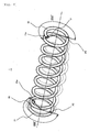
- Fig. 4 is a perspective view illustrating buckling of a spring.
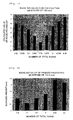
- Fig. 5 is a bar graph illustrating the relationship between a number of total turns of a spring calculated from simulation data and a buckling value.
- Fig. 6 is a bar graph illustrating the relationship between a number of total turns of a spring of a prototype and a buckling value.
- Fig. 7 is a curve graph illustrating amounts of buckling at respective points of several kinds of springs, which are different from one another in number of total turns.
- Fig. 8 shows plan views of both ends of a spring to illustrate the relationship between a number of total turns of a spring and buckling.
- buckling of the spring 1 generally means trunk bending relative to a center line of the spring 1, which is generated when the spring 1 is contracted (see dotted lines in the figure).
- the inventors of the present application have taken notice of a number of total turns, wire diameter, and total length and fixation or non-fixation (upper and lower points slip) of both ends, of the spring 1 to simulate the cause for generation of buckling, and found that an influence due to a number of total turns of the spring 1 is considerable and influence due to other factors are less considerable.
- points P1, P2 of maximum bending at the time of contraction of the spring 1 are present in the neighborhood of those positions on respective first turns 11, 21 on one end side and the other end side of the spring 1, which form about 225° in directions toward second turns (see second turns 12, 22) from terminal ends 11 a, 21 a.
- the points P1, P2 of maximum bending indicate those points on the respective first turns 11, 21, which make maximum displacements when subjected to a compressive load. It is considered that the points P1, P2 of maximum bending make starting points when the spring 1 undergoes buckling. In addition, it is considered that the points P1, P2 of maximum bending are not in agreement with those positions, which form about 225° in directions toward second turns from terminal ends 11 a, 21 a but are present in the neighborhood of about 225°.
- a number of total turns of the spring 1 is represented by the following formula (1) or (2).
- N n + 0.75
- N n ⁇ 0.25
- N number of total turns of a spring and n: integral.
- a number of total turns of the spring 1 may be represented by the following formula (3) or (4).
- N ( n + 0.75 ) ⁇ 0.125
- N ( n ⁇ 0.25 ) ⁇ 0.125
- N number of total turns of a spring and n: integral.
- the spring 1 when used for the suspension unit 114 of a vehicle such as motorcycles, it is possible to effectively reduce buckling of the spring 1 in the suspension unit 114 and the vehicle.
- the spring 1 (the Ti spring) according to the embodiment may mount thereto a spring spacer shown in Fig. 9 to 11.
- Fig. 9 is a perspective view showing a spring spacer mounted to the spring according to the embodiment.
- Fig. 10 is a perspective view showing a state, in which the spring spacer is mounted to the spring according to the embodiment.
- Fig. 11 is a perspective view showing a state, in which the spring spacer and a spring bearing member are mounted to the spring according to the embodiment.
- the spring spacer 5 mainly includes an elastic engagement piece (holding portion) 52 formed contiguous to a side of a plate-shaped contact preventive portion 51 to extend downward to bend outward, and latches 53, 54 provided protrusively at a predetermined interval on a tip end side of the contact preventive portion 51.
- the thickness L1 of the contact preventive portion 51 is made to generate no inconvenience in assembly, as compared with a clearance L2 between a first turn 11 (21) and a second turn 12 (22) of a spring 1, according to the embodiment, shown in Fig. 10, thus making it possible to insert and arrange the contact preventive portion 51 into the clearance L2.
- the contact preventive portion 51 is arcuate to have substantially the same radius of curvature as that of the first turn 11 and the second turn 12 of the spring 1.
- a stepwise recess 51 a is provided on that portion of the contact preventive portion 51, which corresponds to a terminal end 11 a (21 a) of the first turn 11, and the recess 51 a is made smaller in thickness than the remaining portion.
- An inner peripheral surface 52a of the elastic engagement piece 52 is arcuate in cross section to correspond to an inner peripheral surface of the second turn 12 of the spring 1, thus enabling elastically holding the inner peripheral surface of the second turn 12. Further, the inner peripheral surface 52a of the elastic engagement piece 52 is a little smaller in radius of curvature than the inner peripheral surface of the second turn 12 of the spring 1, so that even in the case where a dimensional error appears in the diameter of the second turn 12, a sufficient holding force is obtained.
- a pair of latches 53, 54 include piece members, which are different in height and thickness from each other, and the latch 53 is made large in height and small in thickness as compared with the latch 54, and susceptible to deformation upon application of a load from above. Also, the latch 53 is made substantially triangular in cross section to have a large thickness on a base side thereof whereby it is made hard to deform upon application of a load from laterally. Such latch 53 abuts against the end 11 a of the first turn 11 of the spring 1 to prevent the spring spacer 5 from moving toward the second turn 12.
- the latch 54 is made small in height and large in thickness as compared with the latch 53, and susceptible to deformation upon application of a load from above while deformation is less than that of the latch 53.
- the spring bearing members 2 shown in Fig. 11 is mounted on the terminal end 11a of the first turn 11 of the spring 1, a space toward the first turn 11 is narrowed heightwise, so that movement of the spring spacer 5 toward the first turn 11 is prevented by the latch 54.
- mounting of the spring spacer 5 is completed by mounting the spring bearing members 2 to the first turn 11 of the spring 1. That is, the trunk portion 2a of the spring bearing members 2 is pushed onto an inner periphery of the first turn 11 of the spring 1 to cause the torus-shaped flange portion 2b to abut against a terminal end 11 b of the first turn 11 of the spring 1. Thereby, the trunk portion 2a of the spring bearing members 2 holds down the spring spacer 5 from inside the spring 1, so that coming-out inside the spring 1 is prevented. Also, the elastic engagement piece 52 abuts against the inner peripheral surface of the second turn 12 to prevent coming-out of the spring spacer 5 outside the spring 1.
- the thickness L1 of the contact preventive portion 51 is made a thickness, which does not cause inconvenience in terms of assembly as compared with that clearance L2 between the first turn 11 and the second turn 12 of the spring 1, in which the contact preventive portion 51 is mounted.
- the spring spacer 5 can be readily mounted in the clearance L2 between the first turn 11 and the second turn 12 of the spring 1.
- the invention is not limited to the suspension unit comprising the spring, and the vehicle according to the respective embodiments described above.
- the spring according to the embodiments is not limited to the Ti spring described above but can reduce buckling in various springs other than the Ti spring.
- the spring according to the technical teaching can be applied widely to units other than ones for suspension.
- a spring spacer mounted on the spring is not limited to one according to the embodiment but can be applied various spring spacers, among others those which are disclosed in Patent Application No. 2004-364417, based on which the priority of the present patent application is claimed.
- vehicle to which the present suspension unit and spring are applicable, includes motorcycles and automobiles.
- “motorcycle” means a motorcycle and includes bicycles with a motor (motorbike) and scooters, “motorcycle” specifically meaning a vehicle capable of turning with a vehicle body inclined.
- motorcycle included in “motorcycle” is a vehicle, of which at least one of a front wheel and a rear wheel is made two or more in number and which belongs to tricycles, four-wheel cars (or more) in terms of the number of tires.
- the present spring spacer is applicable to a so-called saddle-ride type vehicle, such as snowmobile, four-wheel buggy (ATV: All Terrain Vehicle), in addition to "motorcycle”.
- the description further discloses an embodiment of a spring, wherein those regions of respective first turns on one end side and the other end side thereof, which form about ⁇ 45° relative to positions of about 225° in directions toward second turns from terminal ends, present a number of total turns not overlapping one another, and directions of bending at the time of contraction are made different on the one end side and the other end side.
- a spring is disclosed, wherein those regions of respective first turns on one end side and the other end side thereof, which form about ⁇ 45° relative to points of maximum bending at the time of contraction, present a number of total turns not overlapping one another, and directions of bending at the time of contraction are made different on the one end side and the other end side.
- any one of the springs structured in the manner described above mounts thereto a spring spacer comprising a contact preventive portion that prevents a terminal end of the first turn from contacting with the second turn.
- the description further discloses an embodiment of a suspension unit comprising any one of the springs structured in the manner described above.
- the spring is made of Ti and a spring bearing member contacting with one end or both ends of the spring is made of Fe.
- the spring is made of Ti
- a spring bearing member contacting with one end or both ends of the spring is made of Al
- a spacer made of a resin is interposed between the spring and the spring bearing member.
- the description further discloses an embodiment of a vehicle comprising a suspension unit provided with any one of the springs structured in the manner described above.
- the description above discloses a particularly preferred embodiment in order to provide a spring capable of reducing buckling at the time of contraction while being simple in structure, a suspension unit, and a vehicle.
- a spring according to the teaching of the description is a structure such that a number of total turns is adjusted to make directions of bending at the time of contraction different on one end side and the other end side.
- those regions of respective first turns 11, 21 on one end side and the other end side, which form about ⁇ 45° relative to positions of about 225° in directions toward second turns from terminal ends 11a, 21a present a number of total turns not overlapping one another, and directions of bending at the time of contraction are made different on one end side and the other end side.
- those regions of respective first turns 11, 21 on one end side and the other end side which form about ⁇ 45° relative to points P1, P2 of maximum bending at the time of contraction, present a number of total turns not overlapping one another, and directions of bending at the time of contraction are made different on one end side and the other end side.
Landscapes
- Engineering & Computer Science (AREA)
- General Engineering & Computer Science (AREA)
- Mechanical Engineering (AREA)
- Springs (AREA)
- Vehicle Body Suspensions (AREA)
- Axle Suspensions And Sidecars For Cycles (AREA)
Abstract
Description
- The present invention relates to a spring capable of reducing buckling (trunk bending relative to a center line of a spring) at the time of contraction, a suspension unit provided with the spring, and a vehicle, such as motorcycles, provided with the suspension unit.
- In recent years, motorcycles used for specific applications such as race or the like adopt springs, which are made of Ti to be lightweight as compared with conventional springs made of Fe, for suspension units or the like. For example, in case of adopting a Ti spring for a suspension unit, a weight can be reduced by 200 to 500 g (by spring constant) in comparison with conventional springs made of Fe (see United States Patent Laid-Open Specification No. 2002/0105127).
- However, in the case where a spring made of a material having a high material strength is to be replaced by a spring made of a material having a low material strength, for example, in the case where a spring made of Fe and mounted in existing suspension units is to be replaced by that spring made of Ti and having the same spring constant as that of the spring made of Fe, wire diameter must be increased in order to ensure the strength for the spring made of Ti.
- Therefore, a clearance between a cylinder, which forms a shock absorber of a suspension unit, and a spring made of Ti and thus replaced is decreased, so that there is a fear that the spring made of Ti undergoes buckling at the time of contraction to contact with the cylinder.
- Hereupon, United States Patent Laid-Open Specification No. 2002/0105127 proposes a spring formed so as to bend a central axis thereof and having respective first turns on both ends thereof inclined relative to spring bearing members, respectively, at a predetermined angle. However, the structure with a central axis of the spring bent involves a fear that a state equivalent to buckling is brought about at the time of contraction of the spring, and the spring comes into contact with a cylinder, which forms the shock absorber, when used for the suspension unit.
- The invention has been thought of in view of the above described situation and has its object to provide a suspension unit capable of reducing buckling at the time of contraction while being simple in structure, and a vehicle.
- This object is solved in an inventive manner by a suspension unit, comprising a spring of which a number of total turns is adjusted to make bending directions in a contracted state of the spring different on one end side and the other end side of the spring.
- According to a preferred embodiment, the suspension unit comprises a first turn at each end side of the spring, each first turn defining a region of ±45° relative to a position of about 225° measured from a terminal end of the first turn in direction towards a second turn of the spring, respectively, wherein said regions at both end sides of the spring are free of overlapping with regard to each other, so as in a contracted state of the spring a bending direction of one end side of the spring is different to a bending direction of the other end side of the spring.
- Preferably, said regions of respective first turns at both end sides of the spring are formed about ±45° relative to points of maximum bending in the contracted state.
- Further, preferably the number of total turns of the spring is represented by the following formula (1) or (2)


where N: number of total turns of a spring and n: integral. - Still further, preferably the number of total turns of the spring (1) is represented by the following formula (3) or (4)


where N: number of total turns of a spring and n: integral. - Beneficially, a spring spacer is mounted to the spring, the spring spacer comprising a contact preventive portion configured to prevent the terminal end of the first turn from contacting with the second turn.
- Further, beneficially the spring is made of a material having a lower material strength than Fe, preferably made of Ti.
- Still further, beneficially at least one spring bearing member contacts with one end or both ends of the spring, the spring bearing member being made of Fe and/or Al.
- Preferably, a spacer made of a resin is interposed between the spring and the spring bearing member.
- The afore-mentioned objective is further solved in an inventive manner by a vehicle, in particular a motorcycle, comprising a suspension unit according to at least one of the above embodiments.
- In the following, the present invention is explained in greater detail with respect to several embodiments thereof in conjunction with the accompanying drawings, wherein:
- Fig. 1
- is a side view showing a part of a vehicle (off-road type motorcycle) according to an embodiment;
- Fig. 2
- is a partially, cross sectional view showing a suspension unit according to the embodiment;
- Fig. 3
- is a partially, cross sectional view showing another suspension unit according to an embodiment;
- Fig. 4
- is a perspective view illustrating buckling of a spring;
- Fig. 5
- is a bar graph illustrating the relationship between a number of total turns of a spring calculated from simulation data and a buckling value;
- Fig. 6
- is a bar graph illustrating the relationship between a number of total turns of a spring of a prototype and a buckling value;
- Fig. 7
- is a curve graph illustrating amounts of buckling at respective points of several kinds of springs, which are different from one another in number of total turns;
- Fig. 8
- shows plan views of both ends of a spring to illustrate the relationship between a number of total turns of a spring and buckling;
- Fig. 9
- is a perspective view showing a spring spacer mounted to the spring according to an embodiment;
- Fig. 10
- is a perspective view showing a state, in which the spring spacer is mounted to the spring according to the embodiment; and
- Fig. 11
- is a perspective view showing a state, in which the spring spacer and a spring bearing member are mounted to the spring according to an embodiment.
- A suspension unit, a spring, and a vehicle according to an embodiment will be described below with reference to the drawings. First, an embodiment of a suspension unit and a vehicle, which are provided with the present spring will be described with reference to Figs. 1 to 3.
- Fig. 1 is a side view showing a part of a vehicle (off-road type motorcycle) according to the embodiment. Also, Figs. 2 and 3 are partial, cross sectional views showing a suspension unit according to the embodiment.
- In Fig. 1, the
reference numeral 100 denotes a rear arm support of an off-road type motorcycle, arear arm bracket 104b is arranged obliquely of a vehicle and downwardly of avehicle frame 104 to diverge and extend vertically, and anair cleaner 107 is arranged in a space surrounded by a seat, left and right seat rails, and left and right seat stays, which are not shown. Theair cleaner 107 is constructed such that an element for filtration of an air is arranged in anair cleaner casing 107a. - A
rear arm 110 is pivotally supported by apivot shaft 111 on a rear and lower end of therear arm bracket 104b to freely swing up and down, and arear wheel 112 is journaled on a rear end of therear arm 110. Therear arm 110 is structured to connect a square-shaped cross pipe 110b between front ends of left andright arm portions rear wheel 112 as possible so as to make a clearance between it and a front edge of the rear wheel minimum whereby a wheel base is shortened and strength and rigidity required for the wholerear arm 110 are ensured. In addition, the left andright arm portions - Also, a
chain casing 105 that covers an upper portion of a drive chain is arranged on theleft arm portion 110a. Afront edge 105a of thechain casing 105 is positioned on an upper surface of the cross pipe 110b. In addition, thechain casing 105 may be omitted from the construction. - A single inverted
type suspension unit 114 is arranged between thevehicle frame 104 and therear arm 110 and on a center line of a vehicle. Thesuspension unit 114 mainly includes, as shown in Fig. 2, acylinder 115, apiston rod 116, areservoir tank 117, a Ti spring (spring) 1, and a linkage 118 (see Fig. 1). - The
cylinder 115 is connected to abracket 104a on a rear and upper end of therear arm bracket 104b as shown in Fig. 1. Also, as shown in Fig. 2, thecylinder 115 is provided on an outer peripheral surface toward an upper end thereof with amale thread 115a, and alock nut 115b and aspring bearing member 2, respectively, are threaded on themale thread 115a. - The
piston rod 116 is connected to a piston (not shown) slidably inserted into thecylinder 115 and projects downward from thecylinder 115. Mounted to a lower end of thepiston rod 116 are a metallicspring bearing member 2 that pairs with thespring bearing member 2,load bearing members spring bearing member 2, and alink portion 116c. - The
reservoir tank 117 is communicated to an interior of thecylinder 115 via a pressure oil flow passage (not shown) to accommodate an increase and a decrease in pressure oil volume in thecylinder 115 when thepiston rod 116 extends and contracts. - The
Ti spring 1 is exteriorly mounted to thecylinder 115 and thepiston rod 116 and held by the pair of the upper and lower bearingmembers Ti spring 1 can be regulated by varying a position, in which thelock nut 115b and thespring bearing member 2 are clamped together. Mounted to theTi spring 1 is a spring spacer 5 (see Figs. 9 to 11), according to the embodiment, described later. - The
linkage 118 includes, as shown in Fig. 1, afirst link 120 pivotally mounted to a lower end of therear arm bracket 104b and asecond link 121 pivotally mounted to a lower surface of the cross pipe 110b. Thepiston rod 116 is connected to therear arm 110 by connecting thelink portion 116c of thepiston rod 116 to thefirst link 120 of thelinkage 118. - Here, the
spring bearing member 2 described above includes a metallic member having aflange portion 2b, which bears a load of theTi spring 1, made integral with a cylindrical-shapedtrunk portion 2a (see Fig. 1 for thetrunk portion 2a and theflange portion 2b). One of thespring bearing members 2 is provided on an inside of thetrunk portion 2a with a female thread (not shown), which is threaded on themale thread 115a of thecylinder 115. - The
spring bearing members 2 support both ends of theTi spring 1 to bear a load thereof (for example, a load of 7500 N at the time of off-road traveling) as shown in Fig. 2. In addition, that surface of theflange portion 2b, which abuts against theTi spring 1, corresponds to "spring bearing surface" that bears a load of theTi spring 1. - According to the embodiment, the respective
spring bearing members 2 in contact with both ends of theTi spring 1 are made of Fe to thereby prevent electrolytic corrosion caused by contact between different metals. That is, Fe is small in electric potential difference relative to Ti as compared with other metals, and in the case where the respectivespring bearing members 2 are made of Fe, it is possible to prevent electrolytic corrosion of thespring bearing members 2 while ensuring durability for a load of theTi spring 1. - Also, as shown in Fig. 3, respective
spring bearing members 3 may be made of Al and spacers 4 made of a resin may be interposed between both ends of theTi spring 1 and the respectivespring bearing members 3. With such construction, electrolytic corrosion of theTi spring 1 and thespring bearing members 3 made of Al can be prevented and lightening of a suspension unit can be achieved by forming the respectivespring bearing members 3 from Al. - Subsequently, the
Ti spring 1 according to the embodiment will be described with reference to Figs. 4 to 8. In addition, for the sake of convenience of explanation, theTi spring 1 according to the embodiment is referred simply below to as "spring 1 ". Also, while Figs. 4 to 8 show not only a spring having constituent features according to the teaching of the present application but also a spring (comparative example) having no constituent features as a comparative example, both springs are referred as "spring 1" in explanation. - Fig. 4 is a perspective view illustrating buckling of a spring. Fig. 5 is a bar graph illustrating the relationship between a number of total turns of a spring calculated from simulation data and a buckling value. Fig. 6 is a bar graph illustrating the relationship between a number of total turns of a spring of a prototype and a buckling value. Fig. 7 is a curve graph illustrating amounts of buckling at respective points of several kinds of springs, which are different from one another in number of total turns. Fig. 8 shows plan views of both ends of a spring to illustrate the relationship between a number of total turns of a spring and buckling.
- In Fig. 4, buckling of the
spring 1 generally means trunk bending relative to a center line of thespring 1, which is generated when thespring 1 is contracted (see dotted lines in the figure). The inventors of the present application have taken notice of a number of total turns, wire diameter, and total length and fixation or non-fixation (upper and lower points slip) of both ends, of thespring 1 to simulate the cause for generation of buckling, and found that an influence due to a number of total turns of thespring 1 is considerable and influence due to other factors are less considerable. - Stated in detail, amounts of buckling were simulated with respect to nine kinds of
springs 1 in the range of a number of total turns of 7.25 to 8.25 (see Fig. 5), and on the basis of results of simulation, an experiment was made on springs of six kinds of prototypes selected carefully in the range of a number of total turns of 7.75 to 8.3 (see Fig. 6). In addition, in the simulation, a length at the time of contraction (stroke) was set to 150.0 mm. On the other hand, since in the experiment on the prototypes contact between wire portions in the neighborhood of full stroke was generated to settle buckling, a length at the time of contraction was set to 112.5 mm. - As the result of both the simulation and the experiment on the prototypes, it is found that amounts of buckling are influenced by a number of total turns of the
springs 1. Also, it has been found that thespring 1 being a suspension spring undergoes less buckling in a case of a number of total turns of 7.75. - Hereupon, amounts of buckling at respective points of a winding were further simulated with respect to nine different kinds of
springs 1, which were the same in number of total turns as those in the simulation described above (see Fig. 7). In Fig. 7, an axis of abscissa indicates respective points of a winding from one end of a spring to the other end thereof, and an axis of ordinate indicates amounts of buckling. Accordingly, it may be considered that shapes of curves of respective curve graphs in the figure indicate curved shapes of springs when buckling is generated intact. - As the result of the simulation, it has been clarified that when a number of total turns is 7.625, 7.75 and 7.875, one end side and the other end side of the
spring 1 are different from each other in direction of bending at the time of contraction and a large buckling is not generally generated. On the contrary, it has been found that when a number of total turns is other than 7.625, 7.75 and 7.875, one end side and the other end side of thespring 1 overlap each other in direction of bending at the time of contraction and a large buckling is generally generated to bend in one direction. - Hereupon, as the result of earnest examination by the inventors of the present application, it is considered that points P1, P2 of maximum bending at the time of contraction of the
spring 1 are present in the neighborhood of those positions on respective first turns 11, 21 on one end side and the other end side of thespring 1, which form about 225° in directions toward second turns (see second turns 12, 22) from terminal ends 11 a, 21 a. - Hereupon, the points P1, P2 of maximum bending indicate those points on the respective first turns 11, 21, which make maximum displacements when subjected to a compressive load. It is considered that the points P1, P2 of maximum bending make starting points when the
spring 1 undergoes buckling. In addition, it is considered that the points P1, P2 of maximum bending are not in agreement with those positions, which form about 225° in directions toward second turns from terminal ends 11 a, 21 a but are present in the neighborhood of about 225°. - Hereupon, the inventors of the present application have found that those regions (see hatched portions in Fig. 8) of the respective first turns 11, 21 on one end side and the other end side of the
spring 1, which form about ±45° relative to positions of about 225° in directions toward the second turns from the terminal ends 11a, 21 a, or the points P1, P2 of maximum bending at the time of contraction, present a number of total turns not overlapping one another. With such construction, one end side and the other end side of thespring 1 were made different from each other in direction of bending at the time of contraction and buckling could not be generally generated. - In order to provide for the construction, a number of total turns of the
spring 1 is represented by the following formula (1) or (2).

where N: number of total turns of a spring and n: integral. - As shown in a plan view of Fig. 8 for (0.75), with a
spring 1 having a number N of total turns that meets the formula (1) or (2), those regions of the respective first turns 11, 21, which form about ±45° relative to positions of about 225° in directions toward the second turns from the terminal ends 11 a, 21 a, or the points P1, P2 of maximum bending at the time of contraction, are positioned on opposite sides and do not overlap each other. In this case, directions of bending at the time of contraction are opposite to each other on one end side and the other end side of thespring 1 to enable reducing buckling most. - Also, a number of total turns of the
spring 1 may be represented by the following formula (3) or (4).

where N: number of total turns of a spring and n: integral. - As shown in a plan view of Fig. 8 for (0.625) or (0.875), with a
spring 1 having a number N of total turns that meets the formula (3) or (4), those regions of the respective first turns 11, 21, which form about ±45° relative to positions of about 225° in directions toward the second turns from the terminal ends 11a, 21 a, or the points P1, P2 of maximum bending at the time of contraction, do not overlap each other. Also, in this case, directions of bending at the time of contraction are opposite to each other on one end side and the other end side of thespring 1 to enable reducing buckling. - On the contrary, in the case where a number of total turns of the
spring 1 may be deduced from the following formulae (5) to (9), it is shown in plan views of Fig. 8 for (0.5), (0.375), (0.25), (0.125) or (0). That is, those regions of the respective first turns 11, 21 of thespring 1, which form about ±45° relative to positions of about 225° in directions toward the second turns from the terminal ends 11a, 21 a, or the points P1, P2 of maximum bending at the time of contraction, overlap each other partially or wholly. As a result, directions of bending at the time of contraction overlap each other on one end side and the other end side of thespring 1, so that a large buckling is generally generated to bend in one direction.


where N: number of total turns of a spring and n: integral. - With the
spring 1 according to the embodiment, a simple construction, in which a number of total turns is adjusted to make directions of bending at the time of contraction different on one end side and the other end side, makes it possible to effectively reduce trunk bending relative to a center line of thespring 1 in one direction, that is, buckling. - Accordingly, when the
spring 1 is used for thesuspension unit 114 of a vehicle such as motorcycles, it is possible to effectively reduce buckling of thespring 1 in thesuspension unit 114 and the vehicle. - As a result, for example, in the case where a spring of small wire diameter made of Fe and mounted in the existing
suspension unit 114 is replaced by that spring made of Ti, which is larger in wire diameter than the spring made of Fe, it is also possible to effectively reduce buckling of the Ti spring to prevent contact with thecylinder 115 of thesuspension unit 114. - More preferably, the spring 1 (the Ti spring) according to the embodiment may mount thereto a spring spacer shown in Fig. 9 to 11. Fig. 9 is a perspective view showing a spring spacer mounted to the spring according to the embodiment. Fig. 10 is a perspective view showing a state, in which the spring spacer is mounted to the spring according to the embodiment. Fig. 11 is a perspective view showing a state, in which the spring spacer and a spring bearing member are mounted to the spring according to the embodiment.
- In Fig. 9, the
spring spacer 5 mainly includes an elastic engagement piece (holding portion) 52 formed contiguous to a side of a plate-shaped contactpreventive portion 51 to extend downward to bend outward, and latches 53, 54 provided protrusively at a predetermined interval on a tip end side of the contactpreventive portion 51. - The thickness L1 of the contact
preventive portion 51 is made to generate no inconvenience in assembly, as compared with a clearance L2 between a first turn 11 (21) and a second turn 12 (22) of aspring 1, according to the embodiment, shown in Fig. 10, thus making it possible to insert and arrange the contactpreventive portion 51 into the clearance L2. Also, the contactpreventive portion 51 is arcuate to have substantially the same radius of curvature as that of thefirst turn 11 and thesecond turn 12 of thespring 1. Further, astepwise recess 51 a is provided on that portion of the contactpreventive portion 51, which corresponds to aterminal end 11 a (21 a) of thefirst turn 11, and therecess 51 a is made smaller in thickness than the remaining portion. - An inner
peripheral surface 52a of theelastic engagement piece 52 is arcuate in cross section to correspond to an inner peripheral surface of thesecond turn 12 of thespring 1, thus enabling elastically holding the inner peripheral surface of thesecond turn 12. Further, the innerperipheral surface 52a of theelastic engagement piece 52 is a little smaller in radius of curvature than the inner peripheral surface of thesecond turn 12 of thespring 1, so that even in the case where a dimensional error appears in the diameter of thesecond turn 12, a sufficient holding force is obtained. - A pair of
latches latch 53 is made large in height and small in thickness as compared with thelatch 54, and susceptible to deformation upon application of a load from above. Also, thelatch 53 is made substantially triangular in cross section to have a large thickness on a base side thereof whereby it is made hard to deform upon application of a load from laterally.Such latch 53 abuts against theend 11 a of thefirst turn 11 of thespring 1 to prevent thespring spacer 5 from moving toward thesecond turn 12. - Also, the
latch 54 is made small in height and large in thickness as compared with thelatch 53, and susceptible to deformation upon application of a load from above while deformation is less than that of thelatch 53. In the case where thespring bearing members 2 shown in Fig. 11 is mounted on theterminal end 11a of thefirst turn 11 of thespring 1, a space toward thefirst turn 11 is narrowed heightwise, so that movement of thespring spacer 5 toward thefirst turn 11 is prevented by thelatch 54. - An explanation is given to a method of mounting the
spring spacer 5, which is structured in the manner described above, on thespring 1. As shown in Fig. 10, as the contactpreventive portion 51 of thespring spacer 5 is inserted into the clearance L2 between thefirst turn 11 and thesecond turn 12 of thespring 1, theelastic engagement piece 52 of thespring spacer 5 is caused to engage with the inner peripheral surface of thesecond turn 12 of thespring 1, thus temporarily latching thespring spacer 5 thereon. - Thereafter, as shown in Fig. 11, mounting of the
spring spacer 5 is completed by mounting thespring bearing members 2 to thefirst turn 11 of thespring 1. That is, thetrunk portion 2a of thespring bearing members 2 is pushed onto an inner periphery of thefirst turn 11 of thespring 1 to cause the torus-shapedflange portion 2b to abut against a terminal end 11 b of thefirst turn 11 of thespring 1. Thereby, thetrunk portion 2a of thespring bearing members 2 holds down thespring spacer 5 from inside thespring 1, so that coming-out inside thespring 1 is prevented. Also, theelastic engagement piece 52 abuts against the inner peripheral surface of thesecond turn 12 to prevent coming-out of thespring spacer 5 outside thespring 1. - In the case where the
spring spacer 5 is mounted to thespring 1, a simple structure surely prevents contact between theterminal end 11 a of thefirst turn 11 and thesecond turn 12 of thespring 1, which is made of Ti or the like and low in surface hardness, to enable achieving an improvement in durability. Accordingly, conjointly with the effect of reducing buckling in thespring 1 according to the embodiment, it is possible to provide thespring 1, thesuspension unit 114, and the vehicle, which are further high in reliability. - Also, the thickness L1 of the contact
preventive portion 51 is made a thickness, which does not cause inconvenience in terms of assembly as compared with that clearance L2 between thefirst turn 11 and thesecond turn 12 of thespring 1, in which the contactpreventive portion 51 is mounted. Thereby, thespring spacer 5 can be readily mounted in the clearance L2 between thefirst turn 11 and thesecond turn 12 of thespring 1. - Besides, with the
spring spacer 5 according to the embodiment, by elastically engaging theelastic engagement piece 52 with the inner peripheral surface of thesecond turn 12 of thespring 1, it is possible to stably hold thespring spacer 5 in the clearance L2 between thefirst turn 11 and thesecond turn 12 of thespring 1. Thereby, mounting of thespring spacer 5 to thespring 1 is made very easy. - In addition, the invention is not limited to the suspension unit comprising the spring, and the vehicle according to the respective embodiments described above. For example, the spring according to the embodiments is not limited to the Ti spring described above but can reduce buckling in various springs other than the Ti spring. Also, the spring according to the technical teaching can be applied widely to units other than ones for suspension.
- Further, a spring spacer mounted on the spring according to the technical teaching is not limited to one according to the embodiment but can be applied various spring spacers, among others those which are disclosed in Patent Application No. 2004-364417, based on which the priority of the present patent application is claimed.
- In addition, while the vehicle has been described as a motorcycle in the embodiments above, it is not limited thereto. Besides, "vehicle", to which the present suspension unit and spring are applicable, includes motorcycles and automobiles. Stated in detail, "motorcycle" means a motorcycle and includes bicycles with a motor (motorbike) and scooters, "motorcycle" specifically meaning a vehicle capable of turning with a vehicle body inclined. Accordingly, included in "motorcycle" is a vehicle, of which at least one of a front wheel and a rear wheel is made two or more in number and which belongs to tricycles, four-wheel cars (or more) in terms of the number of tires. Further, the present spring spacer is applicable to a so-called saddle-ride type vehicle, such as snowmobile, four-wheel buggy (ATV: All Terrain Vehicle), in addition to "motorcycle".
- The description above discloses (amongst others) an embodiment of a spring, of which a number of total turns is adjusted to make directions of bending at the time of contraction different on one end side and the other end side.
- With the spring according to said technical teaching, a simple construction, in which a number of total turns is adjusted to make directions of bending at the time of contraction different on one end side and the other end side, makes it possible to effectively reduce trunk bending relative to a center line of the spring in one direction, that is, buckling.
- The description further discloses an embodiment of a spring, wherein those regions of respective first turns on one end side and the other end side thereof, which form about ±45° relative to positions of about 225° in directions toward second turns from terminal ends, present a number of total turns not overlapping one another, and directions of bending at the time of contraction are made different on the one end side and the other end side.
- According to another aspect of the embodiments thereof, a spring is disclosed, wherein those regions of respective first turns on one end side and the other end side thereof, which form about ±45° relative to points of maximum bending at the time of contraction, present a number of total turns not overlapping one another, and directions of bending at the time of contraction are made different on the one end side and the other end side.
- According to a further aspect of the embodiments, a spring is provided, of which a number of total turns is represented by the following formula (1) or (2)


where N: number of total turns of a spring and n: integral. - According to a further aspect of the embodiments, the description discloses a spring, of which a number of total turns is represented by the following formula (3) or (4)


where N: number of total turns of a spring and n: integral. - Preferably, any one of the springs structured in the manner described above mounts thereto a spring spacer comprising a contact preventive portion that prevents a terminal end of the first turn from contacting with the second turn.
- The description further discloses an embodiment of a suspension unit comprising any one of the springs structured in the manner described above.
- Preferably, the spring is made of Ti and a spring bearing member contacting with one end or both ends of the spring is made of Fe.
- Also, preferably, the spring is made of Ti, a spring bearing member contacting with one end or both ends of the spring is made of Al, and a spacer made of a resin is interposed between the spring and the spring bearing member.
- The description further discloses an embodiment of a vehicle comprising a suspension unit provided with any one of the springs structured in the manner described above.
- Accordingly, when the spring is used for a suspension unit of a vehicle, it is possible to effectively reduce buckling of the spring in the suspension unit and the vehicle.
- The description above discloses a particularly preferred embodiment in order to provide a spring capable of reducing buckling at the time of contraction while being simple in structure, a suspension unit, and a vehicle.
- A spring according to the teaching of the description is a structure such that a number of total turns is adjusted to make directions of bending at the time of contraction different on one end side and the other end side. Preferably, those regions of respective first turns 11, 21 on one end side and the other end side, which form about ±45° relative to positions of about 225° in directions toward second turns from terminal ends 11a, 21a, present a number of total turns not overlapping one another, and directions of bending at the time of contraction are made different on one end side and the other end side. Also, those regions of respective first turns 11, 21 on one end side and the other end side, which form about ±45° relative to points P1, P2 of maximum bending at the time of contraction, present a number of total turns not overlapping one another, and directions of bending at the time of contraction are made different on one end side and the other end side.
Claims (10)
- A suspension unit, comprising a spring (1) of which a number of total turns is adjusted to make bending directions in a contracted state of the spring (1) different on one end side and the other end side of the spring (1).
- A suspension unit according to claim 1, comprising a first turn (11,21) at each end side of the spring (1), each first turn (11,21) defining a region of ±45° relative to a position of about 225° measured from a terminal end (11a,21a) of the first turn (11,21) in direction towards a second turn (12,22) of the spring (1), respectively, wherein said regions at both end sides of the spring (1) are free of overlapping with regard to each other, so as in a contracted state of the spring (1) a bending direction of one end side of the spring (1) is different to a bending direction of the other end side of the spring (1).
- A suspension unit according to claim 1 or 2, wherein said regions of respective first turns (11,21) at both end sides of the spring (1) are formed about ±45° relative to points of maximum bending in the contracted state.
- A suspension unit according to at least one of the claims 1 to 3, wherein the number of total turns of the spring (1) is represented by the following formula (1) or (2)


- A suspension unit according to at least one of the claims 1 to 4, wherein the number of total turns of the spring (1) is represented by the following formula (3) or (4)


- A suspension unit according to at least one of the claims 1 to 5, wherein a spring spacer (5) is mounted to the spring (1), the spring spacer (5) comprising a contact preventive portion (51) configured to prevent the terminal end (11 a,21 a) of the first turn (11,21) from contacting with the second turn (12,22).
- A suspension unit according to at least one of the claims 1 to 6, wherein the spring (1) is made of a material having a lower material strength than Fe, preferably made of Ti.
- A suspension unit according to at least one of the claims 1 to 7, wherein at least one spring bearing member (2,3) contacts with one end or both ends of the spring (1), the spring bearing member (2,3) being made of Fe and/or Al.
- A suspension unit according to claim 8, wherein a spacer (4) made of a resin is interposed between the spring (1) and the spring bearing member (3).
- A vehicle, in particular a motorcycle, comprising a suspension unit according to at least one of the claims 1 to 9.
Applications Claiming Priority (2)
| Application Number | Priority Date | Filing Date | Title |
|---|---|---|---|
| JP2004364417 | 2004-12-16 | ||
| JP2005106919A JP2006194428A (en) | 2004-12-16 | 2005-04-01 | Spring, suspension device and vehicle |
Publications (2)
| Publication Number | Publication Date |
|---|---|
| EP1672240A1 true EP1672240A1 (en) | 2006-06-21 |
| EP1672240B1 EP1672240B1 (en) | 2008-02-20 |
Family
ID=35589474
Family Applications (1)
| Application Number | Title | Priority Date | Filing Date |
|---|---|---|---|
| EP05027640A Expired - Lifetime EP1672240B1 (en) | 2004-12-16 | 2005-12-16 | Spring for suspension unit |
Country Status (6)
| Country | Link |
|---|---|
| US (1) | US7392977B2 (en) |
| EP (1) | EP1672240B1 (en) |
| JP (1) | JP2006194428A (en) |
| AT (1) | ATE386894T1 (en) |
| DE (1) | DE602005004871T2 (en) |
| ES (1) | ES2300929T3 (en) |
Cited By (1)
| Publication number | Priority date | Publication date | Assignee | Title |
|---|---|---|---|---|
| CN103038501A (en) * | 2010-03-31 | 2013-04-10 | 能源配备有限公司 | Actuating systems for controlling the flight of a power wing profile for conversion of wind energy into electrical or mechanical energy |
Families Citing this family (8)
| Publication number | Priority date | Publication date | Assignee | Title |
|---|---|---|---|---|
| JP2006194427A (en) * | 2004-12-16 | 2006-07-27 | Yamaha Motor Co Ltd | Spring spacer, spring, suspension spring, device, suspension device, and vehicle |
| JP4921801B2 (en) | 2006-02-01 | 2012-04-25 | 本田技研工業株式会社 | Rear wheel suspension system for motorcycles |
| US8294767B2 (en) * | 2009-01-30 | 2012-10-23 | Microsoft Corporation | Body scan |
| DE102009051469A1 (en) * | 2009-10-30 | 2011-05-05 | Audi Ag | Suspension for motor vehicles |
| US9452658B2 (en) * | 2015-06-22 | 2016-09-27 | Justin Smith | Convertible link for an anti-sway bar |
| US11199237B2 (en) * | 2018-08-08 | 2021-12-14 | Raptor Performance Shocks, LLC | Internal bypass shock absorber |
| US11446975B2 (en) | 2019-09-20 | 2022-09-20 | Shock Therapy Suspension, Inc. | Convertible link for an anti-sway bar |
| US12385547B2 (en) * | 2021-12-03 | 2025-08-12 | Cane Creek Cycling Components, Inc. | Shock absorption assembly |
Citations (3)
| Publication number | Priority date | Publication date | Assignee | Title |
|---|---|---|---|---|
| US4903985A (en) * | 1987-12-08 | 1990-02-27 | Muhr Und Bender | Wheel suspension |
| US20020105127A1 (en) * | 2001-02-08 | 2002-08-08 | Toshiyuki Imaizumi | Helical compression spring for a vehicle suspension |
| DE10125503C1 (en) * | 2001-05-23 | 2002-12-12 | Muhr & Bender Kg | Arm |
Family Cites Families (6)
| Publication number | Priority date | Publication date | Assignee | Title |
|---|---|---|---|---|
| US5464198A (en) * | 1987-12-11 | 1995-11-07 | Borg-Warner Automotive, Inc. | Torsional vibration damper having helical torsion springs |
| JPH0231032A (en) * | 1988-04-29 | 1990-02-01 | Honda Motor Co Ltd | Spring device |
| US5678809A (en) * | 1994-06-01 | 1997-10-21 | Across Co., Ltd. | Spring members |
| DE19521861C1 (en) * | 1995-06-16 | 1996-10-24 | Porsche Ag | Device for influencing coil spring characteristics of vehicle's wheel suspension |
| JP3061566B2 (en) * | 1996-04-26 | 2000-07-10 | 株式会社エフ・シー・シー | Spring for return mechanism of clutch |
| US6457704B1 (en) * | 2000-11-21 | 2002-10-01 | Meritor Light Vehicle Technology, Llc. | Coil spring noiseguard for a vehicle suspension |
-
2005
- 2005-04-01 JP JP2005106919A patent/JP2006194428A/en not_active Withdrawn
- 2005-12-16 US US11/303,877 patent/US7392977B2/en not_active Expired - Fee Related
- 2005-12-16 AT AT05027640T patent/ATE386894T1/en not_active IP Right Cessation
- 2005-12-16 EP EP05027640A patent/EP1672240B1/en not_active Expired - Lifetime
- 2005-12-16 ES ES05027640T patent/ES2300929T3/en not_active Expired - Lifetime
- 2005-12-16 DE DE602005004871T patent/DE602005004871T2/en not_active Expired - Lifetime
Patent Citations (3)
| Publication number | Priority date | Publication date | Assignee | Title |
|---|---|---|---|---|
| US4903985A (en) * | 1987-12-08 | 1990-02-27 | Muhr Und Bender | Wheel suspension |
| US20020105127A1 (en) * | 2001-02-08 | 2002-08-08 | Toshiyuki Imaizumi | Helical compression spring for a vehicle suspension |
| DE10125503C1 (en) * | 2001-05-23 | 2002-12-12 | Muhr & Bender Kg | Arm |
Cited By (1)
| Publication number | Priority date | Publication date | Assignee | Title |
|---|---|---|---|---|
| CN103038501A (en) * | 2010-03-31 | 2013-04-10 | 能源配备有限公司 | Actuating systems for controlling the flight of a power wing profile for conversion of wind energy into electrical or mechanical energy |
Also Published As
| Publication number | Publication date |
|---|---|
| US20060180966A1 (en) | 2006-08-17 |
| DE602005004871T2 (en) | 2008-05-29 |
| JP2006194428A (en) | 2006-07-27 |
| US7392977B2 (en) | 2008-07-01 |
| EP1672240B1 (en) | 2008-02-20 |
| ES2300929T3 (en) | 2008-06-16 |
| DE602005004871D1 (en) | 2008-04-03 |
| ATE386894T1 (en) | 2008-03-15 |
Similar Documents
| Publication | Publication Date | Title |
|---|---|---|
| US8167325B2 (en) | Control arm of multilink suspension system for vehicle | |
| US8511698B2 (en) | Suspension system for a vehicle | |
| EP1672240B1 (en) | Spring for suspension unit | |
| JP5781155B2 (en) | Post assembly with multi-piece spring seat | |
| US7063179B2 (en) | Tricycle with a rocking mechanism | |
| JP5324101B2 (en) | Flexible axle comprising a trapezoidal cross member, cross member, vehicle, and manufacturing method | |
| US20250065979A1 (en) | Reducer bodies, extender bodies, suspension linkages, and two-wheeled vehicles including the same | |
| US9302706B2 (en) | Articulated connection for transferring a steering movement onto a vehicle wheel | |
| US7527252B2 (en) | Spring spacer for a spring | |
| CN100351111C (en) | Suspension system for a vehicle | |
| JP2007177820A (en) | bush | |
| KR101783329B1 (en) | Suspension coil spring and strut-type suspension device | |
| CN105163963B (en) | bushing for stabilizer | |
| KR102059115B1 (en) | Suspension coil spring | |
| CN1654844A (en) | Coil springs and suspensions | |
| JP2016047722A (en) | Suspension coil spring and strut type suspension device | |
| JP4098898B2 (en) | Strut type suspension system | |
| JP2000110873A (en) | Automotive suspension coil springs | |
| JP2000177346A (en) | Leaf suspension | |
| KR100690365B1 (en) | McPherson Strut Bearing | |
| JP2005083477A (en) | Suspension device | |
| JP2024046588A (en) | Buffer for trailing arm | |
| KR100652163B1 (en) | Tortoise bush of car CTA | |
| KR20040088203A (en) | Bracket of mounting suspension for vehicles | |
| KR20070031101A (en) | Stabilizer bar mounting structure for vehicle suspension |
Legal Events
| Date | Code | Title | Description |
|---|---|---|---|
| PUAI | Public reference made under article 153(3) epc to a published international application that has entered the european phase |
Free format text: ORIGINAL CODE: 0009012 |
|
| 17P | Request for examination filed |
Effective date: 20060222 |
|
| AK | Designated contracting states |
Kind code of ref document: A1 Designated state(s): AT BE BG CH CY CZ DE DK EE ES FI FR GB GR HU IE IS IT LI LT LU LV MC NL PL PT RO SE SI SK TR |
|
| AX | Request for extension of the european patent |
Extension state: AL BA HR MK YU |
|
| 17Q | First examination report despatched |
Effective date: 20060731 |
|
| AKX | Designation fees paid |
Designated state(s): AT BE BG CH CY CZ DE DK EE ES FI FR GB GR HU IE IS IT LI LT LU LV MC NL PL PT RO SE SI SK TR |
|
| GRAP | Despatch of communication of intention to grant a patent |
Free format text: ORIGINAL CODE: EPIDOSNIGR1 |
|
| GRAS | Grant fee paid |
Free format text: ORIGINAL CODE: EPIDOSNIGR3 |
|
| GRAA | (expected) grant |
Free format text: ORIGINAL CODE: 0009210 |
|
| AK | Designated contracting states |
Kind code of ref document: B1 Designated state(s): AT BE BG CH CY CZ DE DK EE ES FI FR GB GR HU IE IS IT LI LT LU LV MC NL PL PT RO SE SI SK TR |
|
| REG | Reference to a national code |
Ref country code: GB Ref legal event code: FG4D |
|
| REG | Reference to a national code |
Ref country code: CH Ref legal event code: EP |
|
| REG | Reference to a national code |
Ref country code: IE Ref legal event code: FG4D |
|
| REF | Corresponds to: |
Ref document number: 602005004871 Country of ref document: DE Date of ref document: 20080403 Kind code of ref document: P |
|
| REG | Reference to a national code |
Ref country code: ES Ref legal event code: FG2A Ref document number: 2300929 Country of ref document: ES Kind code of ref document: T3 |
|
| PG25 | Lapsed in a contracting state [announced via postgrant information from national office to epo] |
Ref country code: IS Free format text: LAPSE BECAUSE OF FAILURE TO SUBMIT A TRANSLATION OF THE DESCRIPTION OR TO PAY THE FEE WITHIN THE PRESCRIBED TIME-LIMIT Effective date: 20080620 Ref country code: FI Free format text: LAPSE BECAUSE OF FAILURE TO SUBMIT A TRANSLATION OF THE DESCRIPTION OR TO PAY THE FEE WITHIN THE PRESCRIBED TIME-LIMIT Effective date: 20080220 |
|
| NLV1 | Nl: lapsed or annulled due to failure to fulfill the requirements of art. 29p and 29m of the patents act | ||
| PG25 | Lapsed in a contracting state [announced via postgrant information from national office to epo] |
Ref country code: AT Free format text: LAPSE BECAUSE OF FAILURE TO SUBMIT A TRANSLATION OF THE DESCRIPTION OR TO PAY THE FEE WITHIN THE PRESCRIBED TIME-LIMIT Effective date: 20080220 |
|
| PG25 | Lapsed in a contracting state [announced via postgrant information from national office to epo] |
Ref country code: LV Free format text: LAPSE BECAUSE OF FAILURE TO SUBMIT A TRANSLATION OF THE DESCRIPTION OR TO PAY THE FEE WITHIN THE PRESCRIBED TIME-LIMIT Effective date: 20080220 Ref country code: SI Free format text: LAPSE BECAUSE OF FAILURE TO SUBMIT A TRANSLATION OF THE DESCRIPTION OR TO PAY THE FEE WITHIN THE PRESCRIBED TIME-LIMIT Effective date: 20080220 Ref country code: PL Free format text: LAPSE BECAUSE OF FAILURE TO SUBMIT A TRANSLATION OF THE DESCRIPTION OR TO PAY THE FEE WITHIN THE PRESCRIBED TIME-LIMIT Effective date: 20080220 Ref country code: BE Free format text: LAPSE BECAUSE OF FAILURE TO SUBMIT A TRANSLATION OF THE DESCRIPTION OR TO PAY THE FEE WITHIN THE PRESCRIBED TIME-LIMIT Effective date: 20080220 |
|
| ET | Fr: translation filed | ||
| PG25 | Lapsed in a contracting state [announced via postgrant information from national office to epo] |
Ref country code: CZ Free format text: LAPSE BECAUSE OF FAILURE TO SUBMIT A TRANSLATION OF THE DESCRIPTION OR TO PAY THE FEE WITHIN THE PRESCRIBED TIME-LIMIT Effective date: 20080220 Ref country code: DK Free format text: LAPSE BECAUSE OF FAILURE TO SUBMIT A TRANSLATION OF THE DESCRIPTION OR TO PAY THE FEE WITHIN THE PRESCRIBED TIME-LIMIT Effective date: 20080220 Ref country code: SK Free format text: LAPSE BECAUSE OF FAILURE TO SUBMIT A TRANSLATION OF THE DESCRIPTION OR TO PAY THE FEE WITHIN THE PRESCRIBED TIME-LIMIT Effective date: 20080220 Ref country code: NL Free format text: LAPSE BECAUSE OF FAILURE TO SUBMIT A TRANSLATION OF THE DESCRIPTION OR TO PAY THE FEE WITHIN THE PRESCRIBED TIME-LIMIT Effective date: 20080220 Ref country code: PT Free format text: LAPSE BECAUSE OF FAILURE TO SUBMIT A TRANSLATION OF THE DESCRIPTION OR TO PAY THE FEE WITHIN THE PRESCRIBED TIME-LIMIT Effective date: 20080721 Ref country code: SE Free format text: LAPSE BECAUSE OF FAILURE TO SUBMIT A TRANSLATION OF THE DESCRIPTION OR TO PAY THE FEE WITHIN THE PRESCRIBED TIME-LIMIT Effective date: 20080520 |
|
| PG25 | Lapsed in a contracting state [announced via postgrant information from national office to epo] |
Ref country code: RO Free format text: LAPSE BECAUSE OF FAILURE TO SUBMIT A TRANSLATION OF THE DESCRIPTION OR TO PAY THE FEE WITHIN THE PRESCRIBED TIME-LIMIT Effective date: 20080220 |
|
| PLBE | No opposition filed within time limit |
Free format text: ORIGINAL CODE: 0009261 |
|
| STAA | Information on the status of an ep patent application or granted ep patent |
Free format text: STATUS: NO OPPOSITION FILED WITHIN TIME LIMIT |
|
| 26N | No opposition filed |
Effective date: 20081121 |
|
| PG25 | Lapsed in a contracting state [announced via postgrant information from national office to epo] |
Ref country code: LT Free format text: LAPSE BECAUSE OF FAILURE TO SUBMIT A TRANSLATION OF THE DESCRIPTION OR TO PAY THE FEE WITHIN THE PRESCRIBED TIME-LIMIT Effective date: 20080220 |
|
| PG25 | Lapsed in a contracting state [announced via postgrant information from national office to epo] |
Ref country code: EE Free format text: LAPSE BECAUSE OF FAILURE TO SUBMIT A TRANSLATION OF THE DESCRIPTION OR TO PAY THE FEE WITHIN THE PRESCRIBED TIME-LIMIT Effective date: 20080220 Ref country code: BG Free format text: LAPSE BECAUSE OF FAILURE TO SUBMIT A TRANSLATION OF THE DESCRIPTION OR TO PAY THE FEE WITHIN THE PRESCRIBED TIME-LIMIT Effective date: 20080520 |
|
| PG25 | Lapsed in a contracting state [announced via postgrant information from national office to epo] |
Ref country code: CY Free format text: LAPSE BECAUSE OF FAILURE TO SUBMIT A TRANSLATION OF THE DESCRIPTION OR TO PAY THE FEE WITHIN THE PRESCRIBED TIME-LIMIT Effective date: 20080220 Ref country code: MC Free format text: LAPSE BECAUSE OF NON-PAYMENT OF DUE FEES Effective date: 20081231 |
|
| PG25 | Lapsed in a contracting state [announced via postgrant information from national office to epo] |
Ref country code: IE Free format text: LAPSE BECAUSE OF NON-PAYMENT OF DUE FEES Effective date: 20081216 |
|
| PG25 | Lapsed in a contracting state [announced via postgrant information from national office to epo] |
Ref country code: HU Free format text: LAPSE BECAUSE OF FAILURE TO SUBMIT A TRANSLATION OF THE DESCRIPTION OR TO PAY THE FEE WITHIN THE PRESCRIBED TIME-LIMIT Effective date: 20080821 Ref country code: LU Free format text: LAPSE BECAUSE OF NON-PAYMENT OF DUE FEES Effective date: 20081216 |
|
| REG | Reference to a national code |
Ref country code: CH Ref legal event code: PL |
|
| PG25 | Lapsed in a contracting state [announced via postgrant information from national office to epo] |
Ref country code: TR Free format text: LAPSE BECAUSE OF FAILURE TO SUBMIT A TRANSLATION OF THE DESCRIPTION OR TO PAY THE FEE WITHIN THE PRESCRIBED TIME-LIMIT Effective date: 20080220 |
|
| PG25 | Lapsed in a contracting state [announced via postgrant information from national office to epo] |
Ref country code: GR Free format text: LAPSE BECAUSE OF FAILURE TO SUBMIT A TRANSLATION OF THE DESCRIPTION OR TO PAY THE FEE WITHIN THE PRESCRIBED TIME-LIMIT Effective date: 20080521 Ref country code: CH Free format text: LAPSE BECAUSE OF NON-PAYMENT OF DUE FEES Effective date: 20091231 Ref country code: LI Free format text: LAPSE BECAUSE OF NON-PAYMENT OF DUE FEES Effective date: 20091231 |
|
| REG | Reference to a national code |
Ref country code: FR Ref legal event code: PLFP Year of fee payment: 11 |
|
| REG | Reference to a national code |
Ref country code: FR Ref legal event code: PLFP Year of fee payment: 12 |
|
| REG | Reference to a national code |
Ref country code: FR Ref legal event code: PLFP Year of fee payment: 13 |
|
| PGFP | Annual fee paid to national office [announced via postgrant information from national office to epo] |
Ref country code: DE Payment date: 20181210 Year of fee payment: 14 |
|
| PGFP | Annual fee paid to national office [announced via postgrant information from national office to epo] |
Ref country code: GB Payment date: 20181218 Year of fee payment: 14 Ref country code: FR Payment date: 20181220 Year of fee payment: 14 |
|
| PGFP | Annual fee paid to national office [announced via postgrant information from national office to epo] |
Ref country code: IT Payment date: 20181220 Year of fee payment: 14 Ref country code: ES Payment date: 20190124 Year of fee payment: 14 |
|
| REG | Reference to a national code |
Ref country code: DE Ref legal event code: R119 Ref document number: 602005004871 Country of ref document: DE |
|
| GBPC | Gb: european patent ceased through non-payment of renewal fee |
Effective date: 20191216 |
|
| PG25 | Lapsed in a contracting state [announced via postgrant information from national office to epo] |
Ref country code: GB Free format text: LAPSE BECAUSE OF NON-PAYMENT OF DUE FEES Effective date: 20191216 Ref country code: DE Free format text: LAPSE BECAUSE OF NON-PAYMENT OF DUE FEES Effective date: 20200701 Ref country code: FR Free format text: LAPSE BECAUSE OF NON-PAYMENT OF DUE FEES Effective date: 20191231 Ref country code: IT Free format text: LAPSE BECAUSE OF NON-PAYMENT OF DUE FEES Effective date: 20191216 |
|
| REG | Reference to a national code |
Ref country code: ES Ref legal event code: FD2A Effective date: 20210526 |
|
| PG25 | Lapsed in a contracting state [announced via postgrant information from national office to epo] |
Ref country code: ES Free format text: LAPSE BECAUSE OF NON-PAYMENT OF DUE FEES Effective date: 20191217 |