EP1672232A1 - Guiding device - Google Patents
Guiding device Download PDFInfo
- Publication number
- EP1672232A1 EP1672232A1 EP04792039A EP04792039A EP1672232A1 EP 1672232 A1 EP1672232 A1 EP 1672232A1 EP 04792039 A EP04792039 A EP 04792039A EP 04792039 A EP04792039 A EP 04792039A EP 1672232 A1 EP1672232 A1 EP 1672232A1
- Authority
- EP
- European Patent Office
- Prior art keywords
- foreign matter
- entry preventing
- moving block
- matter entry
- track rail
- Prior art date
- Legal status (The legal status is an assumption and is not a legal conclusion. Google has not performed a legal analysis and makes no representation as to the accuracy of the status listed.)
- Granted
Links
Images





Classifications
-
- F—MECHANICAL ENGINEERING; LIGHTING; HEATING; WEAPONS; BLASTING
- F16—ENGINEERING ELEMENTS AND UNITS; GENERAL MEASURES FOR PRODUCING AND MAINTAINING EFFECTIVE FUNCTIONING OF MACHINES OR INSTALLATIONS; THERMAL INSULATION IN GENERAL
- F16C—SHAFTS; FLEXIBLE SHAFTS; ELEMENTS OR CRANKSHAFT MECHANISMS; ROTARY BODIES OTHER THAN GEARING ELEMENTS; BEARINGS
- F16C29/00—Bearings for parts moving only linearly
- F16C29/08—Arrangements for covering or protecting the ways
- F16C29/084—Arrangements for covering or protecting the ways fixed to the carriage or bearing body movable along the guide rail or track
- F16C29/088—Seals extending in the longitudinal direction of the carriage or bearing body
-
- F—MECHANICAL ENGINEERING; LIGHTING; HEATING; WEAPONS; BLASTING
- F16—ENGINEERING ELEMENTS AND UNITS; GENERAL MEASURES FOR PRODUCING AND MAINTAINING EFFECTIVE FUNCTIONING OF MACHINES OR INSTALLATIONS; THERMAL INSULATION IN GENERAL
- F16C—SHAFTS; FLEXIBLE SHAFTS; ELEMENTS OR CRANKSHAFT MECHANISMS; ROTARY BODIES OTHER THAN GEARING ELEMENTS; BEARINGS
- F16C29/00—Bearings for parts moving only linearly
- F16C29/04—Ball or roller bearings
- F16C29/06—Ball or roller bearings in which the rolling bodies circulate partly without carrying load
- F16C29/0633—Ball or roller bearings in which the rolling bodies circulate partly without carrying load with a bearing body defining a U-shaped carriage, i.e. surrounding a guide rail or track on three sides
- F16C29/0635—Ball or roller bearings in which the rolling bodies circulate partly without carrying load with a bearing body defining a U-shaped carriage, i.e. surrounding a guide rail or track on three sides whereby the return paths are provided as bores in a main body of the U-shaped carriage, e.g. the main body of the U-shaped carriage is a single part with end caps provided at each end
- F16C29/0638—Ball or roller bearings in which the rolling bodies circulate partly without carrying load with a bearing body defining a U-shaped carriage, i.e. surrounding a guide rail or track on three sides whereby the return paths are provided as bores in a main body of the U-shaped carriage, e.g. the main body of the U-shaped carriage is a single part with end caps provided at each end with balls
- F16C29/0642—Ball or roller bearings in which the rolling bodies circulate partly without carrying load with a bearing body defining a U-shaped carriage, i.e. surrounding a guide rail or track on three sides whereby the return paths are provided as bores in a main body of the U-shaped carriage, e.g. the main body of the U-shaped carriage is a single part with end caps provided at each end with balls with four rows of balls
- F16C29/0647—Ball or roller bearings in which the rolling bodies circulate partly without carrying load with a bearing body defining a U-shaped carriage, i.e. surrounding a guide rail or track on three sides whereby the return paths are provided as bores in a main body of the U-shaped carriage, e.g. the main body of the U-shaped carriage is a single part with end caps provided at each end with balls with four rows of balls with load directions in X-arrangement
-
- F—MECHANICAL ENGINEERING; LIGHTING; HEATING; WEAPONS; BLASTING
- F16—ENGINEERING ELEMENTS AND UNITS; GENERAL MEASURES FOR PRODUCING AND MAINTAINING EFFECTIVE FUNCTIONING OF MACHINES OR INSTALLATIONS; THERMAL INSULATION IN GENERAL
- F16C—SHAFTS; FLEXIBLE SHAFTS; ELEMENTS OR CRANKSHAFT MECHANISMS; ROTARY BODIES OTHER THAN GEARING ELEMENTS; BEARINGS
- F16C29/00—Bearings for parts moving only linearly
- F16C29/08—Arrangements for covering or protecting the ways
- F16C29/084—Arrangements for covering or protecting the ways fixed to the carriage or bearing body movable along the guide rail or track
- F16C29/086—Seals being essentially U-shaped, e.g. for a U-shaped carriage
Definitions
- the present invention relates to a guide apparatus having a track rail and a moving block movably attached to the track rail with rolling elements interposed therebetween. More particularly, the present invention relates to a guide apparatus suitable for use in an environment where fine dust particles are flying.
- a guide apparatus having, as shown in Fig. 1, a track rail 101 and a moving block 102 relatively movably attached to the track rail 101 with a multiplicity of rolling elements (balls or rollers) interposed therebetween (there are cases where the track rail 101 is fixed, and the moving block 102 is movable, and where the moving block 102 is fixed, and the track rail 101 is movable).
- the moving block 102 has a moving block body 103 mounted astride the track rail 101.
- End plates 104 are mounted astride the track rail 101 and secured to both ends of the moving block body 103 in the direction of relative movement.
- Seals 105 are mounted astride the track rail 101 and secured to the respective outer ends of the end plates 104 in the relative movement direction.
- the seals 105 prevent foreign matter from entering the moving block 102 through the gaps between the side surfaces of the track rail 101 and the inner peripheral surfaces of both ends of the moving block 102. Because the seals 105 are attached to the moving block 102, no or very small amount of foreign matter such as fine particles can enter the moving block 102 in an ordinary environment when the guide apparatus is used in such a manner that the track rail 101 is installed on a horizontal plane and the moving block 102 is attached to the horizontally extending track rail 101.
- the guide apparatus When the guide apparatus is used in an ordinary environment and in the position as shown in Fig. 1, as stated above, entry of foreign matter into the moving block 102 will not give rise to a serious problem.
- the guide apparatus may be used in the position shown in Fig. 2, where the track rail 101 is secured to a ceiling surface 106, and the moving block 102 is attached to the track rail 101 on the ceiling surface 106. In other words, the guide apparatus may be used in an inverted position.
- the guide apparatus may also be used in the position shown in Fig. 3, where the track rail 101 is horizontally secured to a wall surface 107, and the moving block 102 is attached to the horizontally extending track rail 101. That is, the guide apparatus may be used in a wall-hung position. As shown in Fig.
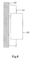
- the guide apparatus may also be used in a position where the track rail 101 is vertically secured to the wall surface 107, and the moving block 102 is attached to the vertically extending track rail 101. That is, the guide apparatus may be used in a vertical position.
- the guide apparatus may be used in any of these positions, particularly in an environment containing many dust particles, foreign matter is likely to enter the moving block 102 through the gaps between the side surfaces of the track rail 101 and the inner side surfaces of the moving block 102, thus preventing smooth rolling of the rolling elements (balls or rollers). This may cause a failure.
- An object of the present invention is to provide a guide apparatus free from the possibility of foreign matter entering the moving block through the gaps between the side surfaces of the track rail and the inner side surfaces of the moving block even in an environment where many fine dust particles are flying.
- the present invention provides a guide apparatus including a track rail having rolling element rolling surfaces extending in the longitudinal direction thereof, and a moving block relatively movably attached to the track rail.
- the moving block has an approximately U-shaped sectional configuration in a plane perpendicular to the longitudinal direction of the track rail.
- the moving block has skirt portions formed at both sides of the opening thereof and is mounted astride the track rail.
- the moving block includes a moving block body having load rolling element rolling surfaces that form load rolling element rolling passages in cooperation with the rolling element rolling surfaces.
- the moving block body further has rolling element relief bores associated with the load rolling element rolling surfaces.
- the moving block further includes end plates mounted astride the track rail and secured to both ends of the moving block body in the direction of relative movement of the moving block.
- the end plates each have rolling element direction change passages that form rolling element recirculation passages in cooperation with the load rolling element rolling passages and the rolling element relief bores.
- a plurality of rolling elements are disposed in the rolling element recirculation passages so as to recirculate in response to relative movement of the track rail and the moving block.
- the guide apparatus is characterized by including foreign matter entry preventing plates provided so that their respective distal ends longitudinally contact the opposite side surfaces of the track rail to close the gaps between the side surfaces of the track rail and at least the inner side surfaces of the skirt portions on both sides of the moving block body and the inner side surfaces of the end plates.
- the guide apparatus is provided with foreign matter entry preventing plates having their respective distal ends longitudinally contacting the opposite side surfaces of the track rail to close the gaps between the side surfaces of the track rail and at least the inner side surfaces of the skirt portions on both sides of the moving block body and the inner side surfaces of the end plates of the moving block. Therefore, there is no possibility of foreign matter, e.g. fine dust particles, entering through the gaps between the side surfaces of the track rail and the inner side surfaces of the skirt portions on both sides of the moving block body and the inner side surfaces of the end plates.
- foreign matter e.g. fine dust particles
- This type of guide apparatus is generally provided with end foreign matter entry preventing devices at both ends of the moving block in the travel direction to prevent entry of foreign matter into the moving block through the gaps between the inner peripheral surfaces of both end portions of the moving block and the outer periphery of the track rail. Therefore, the gaps between the track rail and the moving block are closed by the end foreign matter entry preventing devices and the foreign matter entry preventing plates. Accordingly, it is possible to block foreign matter from entering the moving block substantially completely. Consequently, the plurality of rolling elements disposed in the rolling element recirculation passages of the guide apparatus can perform maintenance-free, smooth rolling for a long period of time.
- the guide apparatus is characterized in that the moving block has a plurality of attachment devices, including lubricators, mounted astride the track rail and secured to the outer ends of the end plates in the direction of relative movement.
- the foreign matter entry preventing plates also close the gaps between the side surfaces of the track rail and the inner side surfaces of the attachment devices.
- the foreign matter entry preventing plates also close the gaps between the side surfaces of the track rail and the inner side surfaces of the attachment devices. Therefore, it is also possible to block foreign matter from entering the attachment devices.
- the guide apparatus is characterized in that the foreign matter entry preventing plates are secured to the respective end surfaces of the skirt portions on both sides of the moving block body.
- the foreign matter entry preventing plates are secured to the respective end surfaces of the skirt portions on both sides of the moving block body. Therefore, it is possible to install the foreign matter entry preventing plates easily using screws or the like while adjusting the contact pressure with the side surfaces of the track rail.
- the guide apparatus according to the present invention is characterized in that the outermost ones of the plurality of attachment devices are metal scrapers formed from metal plates, and the longitudinal end surfaces of the foreign matter entry preventing plates are secured to the metal scrapers.
- the longitudinal end surfaces of the foreign matter entry preventing plates are secured to the metal scrapers. Therefore, the end portions of the foreign matter entry preventing plates are firmly secured. There is no possibility of the end portions of the foreign matter entry preventing plates vibrating or being displaced.
- the foreign matter entry preventing plates can be installed by inserting them from both end sides of the moving block. Thus, the installation operation is facilitated.
- the guide apparatus is characterized in that the foreign matter entry preventing plates each comprise a plate-shaped foreign matter entry preventing plate casing made of a material of high rigidity, and a plate-shaped foreign matter entry preventing plate body made of a flexible material.
- the foreign matter entry preventing plate body is fitted to one side end portion of the foreign matter entry preventing plate casing, and one side end surface of the foreign matter entry preventing plate body is brought into contact with one side surface of the track rail.
- the foreign matter entry preventing plates are each formed by fitting a plate-shaped foreign matter entry preventing plate body made of a flexible material to one side end portion of a foreign matter entry preventing plate casing made of a material of high rigidity. Therefore, the foreign matter entry preventing plates are simple in arrangement and easy to install.
- the guide apparatus is characterized in that the foreign matter entry preventing plates each comprise a plate-shaped foreign matter entry preventing plate casing made of a material of high rigidity, a plate-shaped foreign matter entry preventing plate body made of a flexible material, and a foreign matter entry preventing plate retainer made of a material of high rigidity.
- the foreign matter entry preventing plate casing is secured to the end surface of one of the skirt portions on both sides of the moving block body in a state where one side end surface of the foreign matter entry preventing plate body is brought into contact with one side surface of the track rail and where the foreign matter entry preventing plate body is held between the foreign matter entry preventing plate retainer and the foreign matter entry preventing plate casing.
- the foreign matter entry preventing plates are each installed in such a way that the foreign matter entry preventing plate casing is secured to the end surface of one of the skirt portions on both sides of the moving block body in a state where one side end surface of the foreign matter entry preventing plate body is brought into contact with one side surface of the track rail and where the foreign matter entry preventing plate body is held between the foreign matter entry preventing plate retainer and the foreign matter entry preventing plate casing. Therefore, all the components constituting the foreign matter entry preventing plates have a simple plate-shaped configuration and hence become very easy to machine and less costly.
- the guide apparatus according to the present invention is characterized in that the foreign matter entry preventing plates have their respective side end surfaces perpendicularly contacting the opposite side surfaces of the track rail.
- the foreign matter entry preventing plates have their respective side end surfaces perpendicularly contacting the opposite side surfaces of the track rail. Therefore, entry of foreign matter can be prevented even more effectively.
- the guide apparatus according to the present invention is characterized in that the foreign matter entry preventing plates have self-lubricating capability.
- the foreign matter entry preventing plates have self-lubricating capability. Therefore, even if the side end surface of the foreign matter entry preventing plate body is brought into contact with the track rail side surface at a desired contact pressure, smooth relative movement of the track rail and the guide block is maintained.
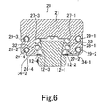
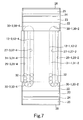
- FIGs. 5 to 8 are diagrams showing the arrangement of a guide apparatus according to the present invention, in which: Fig. 5 is an external perspective view; Fig. 6 is a sectional view taken along the line A-A in Fig. 5; Fig. 7 is a plan view of a moving block; and Fig. 8 is an exploded perspective view of the moving block.
- a track rail 11 is formed with a plurality (four in the illustrated example) of longitudinally extending rolling element rolling grooves 12-1 to 12-4 along which rolling elements (balls) roll.
- a moving block 20 is movably attached to the track rail 11.
- the moving block 20 has a moving block body 21 and end plates 22 secured to both ends of the moving block body 21 in the travel direction of the moving block 20.
- Lubricators 23 are secured to the respective outer ends of the end plates 22 in the travel direction.
- End seals 24 are secured to the respective outer ends of the lubricators 23 in the travel direction.
- Laminated contact scrapers 25 are secured to the respective outer ends of the end seals 24 in the travel direction.
- Metal scrapers 26 are secured to the respective outer ends of the laminated contact scrapers 25 in the travel direction.
- the moving block body 21 has a U-shaped sectional configuration in a plane perpendicular to the longitudinal direction of the track rail 11.
- the moving block body 21 has skirt portions 28-1 and 28-2 formed at both sides of the opening thereof.
- the moving block body 21 is mounted astride the track rail 11.
- the moving block body 21 is formed with a plurality (four in the illustrated example) of load rolling element rolling grooves 27-1 to 27-4 that form load rolling element rolling passages 31-1 to 31-4 in cooperation with the rolling element rolling grooves 12-1 to 12-4 formed on the track rail 11. Further, the moving block body 21 is formed with rolling element relief bores 29-1 to 29-4, the number of which corresponds to the number of load rolling element rolling grooves 27-1 to 27-4.
- the end plates 22 have a U-shaped sectional configuration in a plane perpendicular to the longitudinal direction of the track rail 11.
- the end plates 22 are mounted astride the track rail 11 and secured to both ends of the moving block body 21.
- the end plates 22 are formed with rolling element direction change passages 30-1 to 30-4, respectively.
- the rolling element direction change passages 30-1 communicate between the rolling element relief bore 29-1 and the load rolling element rolling passage 31-1, which is formed by the rolling element rolling groove 12-1 of the track rail 11 and the load rolling element rolling groove 27-1 of the moving block body 21, to form a rolling element recirculation passage.
- the rolling element direction change passages 30-2 communicate between the rolling element relief bore 29-2 and the load rolling element rolling passage 31-2, which is formed by the rolling element rolling groove 12-2 of the track rail 11 and the load rolling element rolling groove 27-2 of the moving block body 21, to form a rolling element recirculation passage.
- the rolling element direction change passages 30-3 communicate between the rolling element relief bore 29-3 and the load rolling element rolling passage 31-3, which is formed by the rolling element rolling groove 12-3 of the track rail 11 and the load rolling element rolling groove 27-3 of the moving block body 21, to form a rolling element recirculation passage.
- the rolling element direction change passages 30-4 communicate between the rolling element relief bore 29-4 and the load rolling element rolling passage 31-4, which is formed by the rolling element rolling groove 12-4 of the track rail 11 and the load rolling element rolling groove 27-4 of the moving block body 21, to form a rolling element recirculation passage.
- Rolling elements (balls) 32 recirculate through the rolling element recirculation passages in response to the relative movement of the track rail 11 and the moving block 20.
- the lubricators 23 supply lubricant to the rolling element rolling grooves 12-1 to 12-4 of the track rail 11.
- the lubricators 23 have a U-shaped sectional configuration in a plane perpendicular to the longitudinal direction of the track rail 11.
- the lubricators 23 are mounted astride the track rail 11 and secured to the respective outer ends of the end plates 22 in the travel direction.
- the end seals 24 prevent foreign matter adhering to the surface of the track rail 11 from entering the moving block 20.
- the end seals 24 have a U-shaped sectional configuration in a plane perpendicular to the longitudinal direction of the track rail 11.
- the end seals 24 are mounted astride the track rail 11 and secured to the respective outer ends of the lubricators 23 in the travel direction.
- the inner peripheral surfaces of the end seals 24 are in contact with the surface of the track rail 11.
- the laminated contact scrapers 25 prevent minute foreign matter from entering the moving block 20.
- the laminated contact scrapers 25 have a U-shaped sectional configuration in a plane perpendicular to the longitudinal direction of the track rail 11.
- Each laminated contact scraper 25 has a plurality of felt-like plate materials laminated in the travel direction within a casing.
- the laminated contact scrapers 25 are mounted astride the track rail 11 with their inner peripheral surfaces being in contact with the surface of the track rail 11. In this state, the laminated contact scrapers 25 are secured to the respective outer ends of the end seals 24 in the travel direction.
- the metal scrapers 26 remove relatively large foreign objects such as chips, spatter and dust.
- the metal scrapers 26 have a U-shaped sectional configuration in a plane perpendicular to the longitudinal direction of the track rail 11.
- the metal scrapers 26 are mounted astride the track rail 11 with their inner peripheral surfaces being out of contact with the surface of the track rail 11. In this state, the metal scrapers 26 are secured to the respective outer ends of the laminated contact scrapers 25 in the travel direction.
- the end plates 22, the lubricators 23, the end seals 24, the laminated contact scrapers 25 and the metal scrapers 26 are stacked, respectively, and, in this state, secured to both ends of the moving block body 21 with screws 33.
- Foreign matter entry preventing plates 34 are secured to the respective lower end surfaces of the skirt portions 28-1 and 28-2 (see Fig. 6) of the moving block body 21 with screws 35.
- the respective distal end surfaces of the foreign matter entry preventing plates 34 longitudinally contact the opposite side surfaces of the track rail 11 to close the gaps between the inner side surfaces of the moving block 20 and the side surfaces of the track rail 11, thereby preventing foreign matter such as fine dust particles from entering the inside through the gaps.
- Fig. 9 is a diagram showing a structural example of the foreign matter entry preventing plates.
- Fig. 9A is a plan view
- Fig. 9B is an enlarged end side view.
- Each foreign matter entry preventing plate 34 comprises a foreign matter entry preventing plate body 36 and a foreign matter entry preventing plate casing 37.
- the foreign matter entry preventing plate body 36 is a plate-shaped member of continuous length made of a flexible resin material (e.g. urethane pad) or the like.
- the foreign matter entry preventing plate casing 37 is a plate-shaped member made of a material of high rigidity, e.g. a resin or metal material, and has a U-shaped groove 38 formed in one side end surface thereof.
- U-shaped groove 38 One side end portion of the foreign matter entry preventing plate body 36 is insertable into the U-shaped groove 38.
- a plurality (three in the illustrated example) of U-shaped grooves 40 for forming screw holes 39 are formed in one surface of the other side end portion of the foreign matter entry preventing plate casing 37.
- Elliptic screw holes 39 are formed in the respective centers of the U-shaped grooves 40.
- Screw holes 42 are also formed in both end surfaces of the foreign matter entry preventing plate casing 37.
- the U-shaped grooves 40 each have such a depth that the head of a screw 35 will not project from the surface of the foreign matter entry preventing plate casing 37 when the screw 35 is inserted into the associated screw hole 39.
- the foreign matter entry preventing plate body 36 is inserted into the U-shaped groove 38 of the foreign matter entry preventing plate casing 37 and bonded with an adhesive, thereby fitting the foreign matter entry preventing plate body 36 to the foreign matter entry preventing plate casing 37.
- the foreign matter entry preventing plate body 36 arranged as stated above is secured to the end surface of one of the skirt portions 28-1 and 28-2 on both sides of the moving block body 21 with screws 35 (see Fig. 8) inserted into the screw holes 39.
- the foreign matter entry preventing plate body 36 extends perpendicular to one side surface of the track rail 11, and one side end surface thereof is in contact with the side surface of the track rail 11 (see Fig. 6).
- the contact pressure of the one side end surface of the foreign matter entry preventing plate body 36 can be adjusted because the screw holes 39 are elliptical. More specifically, with the screws 35 untightened, the foreign matter entry preventing plate casing 37 is pressed toward the track rail 11, and after the pressing force has been adjusted, the screws 35 are tightened.
- the foreign matter entry preventing plates 34 have such a length that they fit between the metal scrapers 26 at both ends of the moving block 20. Screws 44 are inserted into respective screw holes 43 (see Fig. 8) formed in the metal scrapers 26, and the distal end portions of the screws 44 are screwed into the screw holes 42 on the end surfaces of the foreign matter entry preventing plate casings 37 to secure the end surfaces of the foreign matter entry preventing plates 34 to the side surfaces of the metal scrapers 26. With this arrangement, there is no possibility of the end portions of the foreign matter entry preventing plates 34 vibrating or being displaced.
- the foreign matter entry preventing plates 34 can be installed by inserting them between the metal scrapers 26 and securing the foreign matter entry preventing plates 34 to the metal scrapers 26 with the screws 44 from both end surface sides of the moving block 20.
- the foreign matter entry preventing plate body 36 is formed by using a material impregnable with lubricant, e.g. urethane foam, and impregnating it with lubricant, thereby allowing the foreign matter entry preventing plate body 36 to have self-lubricating capability.
- the foreign matter entry preventing plates 34 are arranged as stated above to close the gaps between the side surfaces of the track rail 11 and the inner side surfaces of the moving block 20, which comprises the moving block body 21, the end plates 22, the lubricators 23, the end seals 24, the laminated contact scrapers 25 and the metal scrapers 26, except the metal scrapers 26, which are attachment devices. Therefore, there is also no possibility of foreign matter entering the attachment devices, i.e. the lubricators 23, the end seals 24, and the laminated contact scrapers 25. Moreover, the end seals 24 and the laminated contact scrapers 25 prevent foreign matter from entering the moving block body 21 through the end portions thereof. Therefore, entry of foreign matter into the moving block 20 can be blocked substantially perfectly.
- the guide apparatus arranged as stated above is suitable for use in machines used in an environment where dust particles are flying, e.g. wood working machines in which wood chips or shavings are generated, cutting machines where plaster dust is generated, grinding machines where grinding dust is generated, carpet cutting machines where fabric dust is generated, cleaning machines handling water and chemicals, machine tools where coolant is generated, and various outdoor machines where dust is generated.
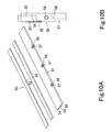
- FIG. 10 is a diagram showing another structural example of the foreign matter entry preventing plates.
- Fig. 10A is an exploded perspective view
- Fig. 10B is an enlarged end side view.
- a foreign matter entry preventing plate 50 comprises a foreign matter entry preventing plate casing 51, a foreign matter entry preventing plate body 52, and a foreign matter entry preventing plate retainer 53.
- the foreign matter entry preventing plate casing 51 is made of a material of high rigidity, e.g. a resin or metal material.
- the foreign matter entry preventing plate casing 51 has stepped portions 54 and 55 formed in one surface of one side end portion thereof.
- the stepped portion 54 accommodates one side portion of the foreign matter entry preventing plate body 52.
- the stepped portion 55 accommodates one side portion of the foreign matter entry preventing plate retainer 53.
- a plurality (three in the illustrated example) of U-shaped grooves 56 for forming screw holes 57 are formed in one surface of the other side end portion of the foreign matter entry preventing plate casing 51 (i.e. the surface opposite to the surface formed with the stepped portions 54 and 55). Screw holes 57 are formed in the respective centers of the U-shaped grooves 56. Screw holes 58 are also formed in both end surfaces of the foreign matter entry preventing plate casing 51.
- the U-shaped grooves 56 have such a depth that the head of a screw 35 (see Fig. 8) will not project from the surface of the foreign matter entry preventing plate casing 51 when the screw 35 is inserted into the associated screw hole 57.
- the foreign matter entry preventing plate body 52 is a plate-shaped member of continuous length made of a flexible resin material (e.g. urethane pad) or the like.
- the foreign matter entry preventing plate retainer 53 is made of a material of high rigidity, e.g. a resin or metal material.
- one side portion of the foreign matter entry preventing plate body 52 is accommodated in the stepped portion 54 of the foreign matter entry preventing plate casing 51, and one side portion of the foreign matter entry preventing plate retainer 53 is accommodated in the stepped portion 55 of the foreign matter entry preventing plate casing 51, thereby holding the foreign matter entry preventing plate body 52 between the foreign matter entry preventing plate casing 51 and the foreign matter entry preventing plate retainer 53.
- the foreign matter entry preventing plate body 52 is positioned to extend perpendicular to one side surface of the track rail 11, and one side end surface thereof is brought into contact with the side surface of the track rail 11. In this state, the foreign matter entry preventing plate casing 51 is secured to the end surface of one of the skirt portions 28-1 and 28-2 on both sides of the moving block body 21 with screws 35 inserted into the screw holes 57.
- the foreign matter entry preventing plate body 52 is formed by using a material impregnable with lubricant, e.g. urethane foam, and impregnating it with lubricant, thereby allowing the foreign matter entry preventing plate body 36 to have self-lubricating capability.
- the foreign matter entry preventing plate body 52 and the foreign matter entry preventing plate casing 51 are bonded together with an adhesive, and the foreign matter entry preventing plate body 52 and the foreign matter entry preventing plate retainer 53 are also bonded together with an adhesive.
- Screws 44 are inserted into the respective screw holes 43, which are formed in the metal scrapers 26, and screwed into the screw holes 58 on the end surfaces of the foreign matter entry preventing plate casings 51 to secure the end surfaces of the foreign matter entry preventing plates 50 to the side surfaces of the metal scrapers 26.
- the components constituting the foreign matter entry preventing plate 50 i.e. the foreign matter entry preventing plate casing 51, the foreign matter entry preventing plate body 52, and the foreign matter entry preventing plate retainer 53, each have a plate-shaped configuration and hence become easy to machine. Particularly, it becomes unnecessary to perform machining to form the U-shaped groove 38 as provided in the foreign matter entry preventing plate casing 37 of thin wall thickness, shown in Fig. 9, for inserting one side end portion of the foreign matter entry preventing plate body 36. Therefore, machining of the components becomes very easy, and costs are reduced. It should be noted that the operation and effect of the foreign matter entry preventing plate 50 are substantially the same as those of the foreign matter entry preventing plate 34 arranged as shown in Fig. 9.
- the present invention is not necessarily limited to the above-described embodiments but can be modified in a variety of ways.
- the balls 32 are used as the rolling elements in the foregoing embodiments, the rolling elements are not necessarily limited to balls but may be rollers.
- the track rail 11 is fixed, and the moving block 20 is movable. The arrangement may, however, be such that the moving block 20 is fixed, and the track rail 11 is movable.
- the guide apparatus can be used in any position, e.g. an inverted, wall-hung or vertical position as shown in Figs. 2 to 4, besides the above-mentioned position.
- the present invention is a guide apparatus including a track rail having rolling element rolling surfaces extending in the longitudinal direction thereof, and a moving block relatively movably attached to the track rail.
- the moving block has an approximately U-shaped sectional configuration in a plane perpendicular to the longitudinal direction of the track rail.
- the moving block has skirt portions formed at both sides of the opening thereof and is mounted astride the track rail.
- the moving block includes a moving block body having load rolling element rolling surfaces that form load rolling element rolling passages in cooperation with the rolling element rolling surfaces.
- the moving block body further has rolling element relief bores associated with the load rolling element rolling surfaces.
- the moving block further includes end plates mounted astride the track rail and secured to both ends of the moving block body in the direction of relative movement of the moving block.
- the end plates each have rolling element direction change passages that form rolling element recirculation passages in cooperation with the load rolling element rolling passages and the rolling element relief bores.
- a plurality of rolling elements are disposed in the rolling element recirculation passages so as to recirculate in response to relative movement of the track rail and the moving block.
- the guide apparatus is provided with foreign matter entry preventing plates having their respective distal ends longitudinally contacting the opposite side surfaces of the track rail to close the gaps between the side surfaces of the track rail and at least the inner side surfaces of the skirt portions on both sides of the moving block body and the inner side surfaces of the end plates. Therefore, there is no possibility of foreign matter, e.g.
- This type of guide apparatus is generally provided with end foreign matter entry preventing devices at both ends of the moving block in the travel direction to prevent entry of foreign matter into the moving block through the gaps between the inner peripheral surfaces of both end portions of the moving block and the outer periphery of the track rail. Therefore, the gaps between the track rail and the moving block are closed by the end foreign matter entry preventing devices and the foreign matter entry preventing plates. Accordingly, it is possible to block foreign matter from entering the moving block substantially completely. Consequently, the plurality of rolling elements disposed in the rolling element recirculation passages of the guide apparatus can perform maintenance-free, smooth rolling for a long period of time.
- the moving block has a plurality of attachment devices, including lubricators, mounted astride the track rail and secured to the outer ends of the end plates in the direction of relative movement.
- the foreign matter entry preventing plates also close the gaps between the side surfaces of the track rail and the inner side surfaces of the attachment devices. Therefore, it is also possible to block foreign matter from entering the attachment devices.
- the foreign matter entry preventing plates are secured to the respective end surfaces of the skirt portions on both sides of the moving block body. Therefore, it is possible to install the foreign matter entry preventing plates easily using screws or the like while adjusting the contact pressure with the side surfaces of the track rail.
- the outermost ones of the plurality of attachment devices are metal scrapers formed from metal plates, and the longitudinal end surfaces of the foreign matter entry preventing plates are secured to the metal scrapers. Therefore, the end portions of the foreign matter entry preventing plates are firmly secured. There is no possibility of the end portions of the foreign matter entry preventing plates vibrating or being displaced.
- the gaps between the end surfaces of the two skirt portions of the moving block and the base surface to which the track rail is secured are narrow, the foreign matter entry preventing plates can be installed by inserting them from both end sides of the moving block. Thus, the installation operation is facilitated.
- the foreign matter entry preventing plates each comprise a plate-shaped foreign matter entry preventing plate casing made of a material of high rigidity, and a plate-shaped foreign matter entry preventing plate body made of a flexible material.
- the foreign matter entry preventing plate body is fitted to one side end portion of the foreign matter entry preventing plate casing, and one side end surface of the foreign matter entry preventing plate body is brought into contact with one side surface of the track rail. Therefore, the foreign matter entry preventing plates are simple in arrangement and easy to install.
- the foreign matter entry preventing plates each comprise a plate-shaped foreign matter entry preventing plate casing made of a material of high rigidity, a plate-shaped foreign matter entry preventing plate body made of a flexible material, and a foreign matter entry preventing plate retainer made of a material of high rigidity.
- the foreign matter entry preventing plate casing is secured to the end surface of one of the skirt portions on both sides of the moving block body in a state where one side end surface of the foreign matter entry preventing plate body is brought into contact with one side surface of the track rail and where the foreign matter entry preventing plate body is held between the foreign matter entry preventing plate retainer and the foreign matter entry preventing plate casing. Therefore, all the components constituting the foreign matter entry preventing plates have a simple plate-shaped configuration and hence become very easy to machine and less costly.
- the foreign matter entry preventing plates have their respective side end surfaces perpendicularly contacting the opposite side surfaces of the track rail. Therefore, entry of foreign matter can be prevented even more effectively.
- the foreign matter entry preventing plates have self-lubricating capability. Therefore, even if the side end surface of the foreign matter entry preventing plate body is brought into contact with the track rail side surface at a desired contact pressure, smooth relative movement of the track rail and the guide block is maintained.
- FIG. 1 is an external perspective view showing a structural example of a guide apparatus.
Landscapes
- Engineering & Computer Science (AREA)
- General Engineering & Computer Science (AREA)
- Mechanical Engineering (AREA)
- Bearings For Parts Moving Linearly (AREA)
Abstract
Description
- The present invention relates to a guide apparatus having a track rail and a moving block movably attached to the track rail with rolling elements interposed therebetween. More particularly, the present invention relates to a guide apparatus suitable for use in an environment where fine dust particles are flying.
- There is a guide apparatus having, as shown in Fig. 1, a
track rail 101 and a movingblock 102 relatively movably attached to thetrack rail 101 with a multiplicity of rolling elements (balls or rollers) interposed therebetween (there are cases where thetrack rail 101 is fixed, and themoving block 102 is movable, and where themoving block 102 is fixed, and thetrack rail 101 is movable). In such a guide apparatus, the movingblock 102 has a movingblock body 103 mounted astride thetrack rail 101.End plates 104 are mounted astride thetrack rail 101 and secured to both ends of the movingblock body 103 in the direction of relative movement.Seals 105 are mounted astride thetrack rail 101 and secured to the respective outer ends of theend plates 104 in the relative movement direction. - The
seals 105 prevent foreign matter from entering the movingblock 102 through the gaps between the side surfaces of thetrack rail 101 and the inner peripheral surfaces of both ends of themoving block 102. Because theseals 105 are attached to themoving block 102, no or very small amount of foreign matter such as fine particles can enter the movingblock 102 in an ordinary environment when the guide apparatus is used in such a manner that thetrack rail 101 is installed on a horizontal plane and the movingblock 102 is attached to the horizontally extendingtrack rail 101. - When the guide apparatus is used in an ordinary environment and in the position as shown in Fig. 1, as stated above, entry of foreign matter into the moving
block 102 will not give rise to a serious problem. The guide apparatus, however, may be used in the position shown in Fig. 2, where thetrack rail 101 is secured to aceiling surface 106, and the movingblock 102 is attached to thetrack rail 101 on theceiling surface 106. In other words, the guide apparatus may be used in an inverted position. The guide apparatus may also be used in the position shown in Fig. 3, where thetrack rail 101 is horizontally secured to awall surface 107, and the movingblock 102 is attached to the horizontally extendingtrack rail 101. That is, the guide apparatus may be used in a wall-hung position. As shown in Fig. 4, the guide apparatus may also be used in a position where thetrack rail 101 is vertically secured to thewall surface 107, and the movingblock 102 is attached to the vertically extendingtrack rail 101. That is, the guide apparatus may be used in a vertical position. When the guide apparatus is used in any of these positions, particularly in an environment containing many dust particles, foreign matter is likely to enter the movingblock 102 through the gaps between the side surfaces of thetrack rail 101 and the inner side surfaces of themoving block 102, thus preventing smooth rolling of the rolling elements (balls or rollers). This may cause a failure. - The present invention was made in view of the above-described circumstances. An object of the present invention is to provide a guide apparatus free from the possibility of foreign matter entering the moving block through the gaps between the side surfaces of the track rail and the inner side surfaces of the moving block even in an environment where many fine dust particles are flying.
- To attain the above-described object, the present invention provides a guide apparatus including a track rail having rolling element rolling surfaces extending in the longitudinal direction thereof, and a moving block relatively movably attached to the track rail. The moving block has an approximately U-shaped sectional configuration in a plane perpendicular to the longitudinal direction of the track rail. The moving block has skirt portions formed at both sides of the opening thereof and is mounted astride the track rail. The moving block includes a moving block body having load rolling element rolling surfaces that form load rolling element rolling passages in cooperation with the rolling element rolling surfaces. The moving block body further has rolling element relief bores associated with the load rolling element rolling surfaces. The moving block further includes end plates mounted astride the track rail and secured to both ends of the moving block body in the direction of relative movement of the moving block. The end plates each have rolling element direction change passages that form rolling element recirculation passages in cooperation with the load rolling element rolling passages and the rolling element relief bores. A plurality of rolling elements are disposed in the rolling element recirculation passages so as to recirculate in response to relative movement of the track rail and the moving block. The guide apparatus is characterized by including foreign matter entry preventing plates provided so that their respective distal ends longitudinally contact the opposite side surfaces of the track rail to close the gaps between the side surfaces of the track rail and at least the inner side surfaces of the skirt portions on both sides of the moving block body and the inner side surfaces of the end plates.
- Thus, the guide apparatus is provided with foreign matter entry preventing plates having their respective distal ends longitudinally contacting the opposite side surfaces of the track rail to close the gaps between the side surfaces of the track rail and at least the inner side surfaces of the skirt portions on both sides of the moving block body and the inner side surfaces of the end plates of the moving block. Therefore, there is no possibility of foreign matter, e.g. fine dust particles, entering through the gaps between the side surfaces of the track rail and the inner side surfaces of the skirt portions on both sides of the moving block body and the inner side surfaces of the end plates. This type of guide apparatus is generally provided with end foreign matter entry preventing devices at both ends of the moving block in the travel direction to prevent entry of foreign matter into the moving block through the gaps between the inner peripheral surfaces of both end portions of the moving block and the outer periphery of the track rail. Therefore, the gaps between the track rail and the moving block are closed by the end foreign matter entry preventing devices and the foreign matter entry preventing plates. Accordingly, it is possible to block foreign matter from entering the moving block substantially completely. Consequently, the plurality of rolling elements disposed in the rolling element recirculation passages of the guide apparatus can perform maintenance-free, smooth rolling for a long period of time.
- In addition, the guide apparatus according to the present invention is characterized in that the moving block has a plurality of attachment devices, including lubricators, mounted astride the track rail and secured to the outer ends of the end plates in the direction of relative movement. The foreign matter entry preventing plates also close the gaps between the side surfaces of the track rail and the inner side surfaces of the attachment devices.
- Thus, the foreign matter entry preventing plates also close the gaps between the side surfaces of the track rail and the inner side surfaces of the attachment devices. Therefore, it is also possible to block foreign matter from entering the attachment devices.
- In addition, the guide apparatus according to the present invention is characterized in that the foreign matter entry preventing plates are secured to the respective end surfaces of the skirt portions on both sides of the moving block body.
- Thus, the foreign matter entry preventing plates are secured to the respective end surfaces of the skirt portions on both sides of the moving block body. Therefore, it is possible to install the foreign matter entry preventing plates easily using screws or the like while adjusting the contact pressure with the side surfaces of the track rail.
- In addition, the guide apparatus according to the present invention is characterized in that the outermost ones of the plurality of attachment devices are metal scrapers formed from metal plates, and the longitudinal end surfaces of the foreign matter entry preventing plates are secured to the metal scrapers.
- Thus, the longitudinal end surfaces of the foreign matter entry preventing plates are secured to the metal scrapers. Therefore, the end portions of the foreign matter entry preventing plates are firmly secured. There is no possibility of the end portions of the foreign matter entry preventing plates vibrating or being displaced. When the gaps between the end surfaces of the two skirt portions of the moving block and the base surface to which the track rail is secured are narrow, the foreign matter entry preventing plates can be installed by inserting them from both end sides of the moving block. Thus, the installation operation is facilitated.
- In addition, the guide apparatus according to the present invention is characterized in that the foreign matter entry preventing plates each comprise a plate-shaped foreign matter entry preventing plate casing made of a material of high rigidity, and a plate-shaped foreign matter entry preventing plate body made of a flexible material. The foreign matter entry preventing plate body is fitted to one side end portion of the foreign matter entry preventing plate casing, and one side end surface of the foreign matter entry preventing plate body is brought into contact with one side surface of the track rail.
- Thus, the foreign matter entry preventing plates are each formed by fitting a plate-shaped foreign matter entry preventing plate body made of a flexible material to one side end portion of a foreign matter entry preventing plate casing made of a material of high rigidity. Therefore, the foreign matter entry preventing plates are simple in arrangement and easy to install.
- In addition, the guide apparatus according to the present invention is characterized in that the foreign matter entry preventing plates each comprise a plate-shaped foreign matter entry preventing plate casing made of a material of high rigidity, a plate-shaped foreign matter entry preventing plate body made of a flexible material, and a foreign matter entry preventing plate retainer made of a material of high rigidity. The foreign matter entry preventing plate casing is secured to the end surface of one of the skirt portions on both sides of the moving block body in a state where one side end surface of the foreign matter entry preventing plate body is brought into contact with one side surface of the track rail and where the foreign matter entry preventing plate body is held between the foreign matter entry preventing plate retainer and the foreign matter entry preventing plate casing.
- Thus, the foreign matter entry preventing plates are each installed in such a way that the foreign matter entry preventing plate casing is secured to the end surface of one of the skirt portions on both sides of the moving block body in a state where one side end surface of the foreign matter entry preventing plate body is brought into contact with one side surface of the track rail and where the foreign matter entry preventing plate body is held between the foreign matter entry preventing plate retainer and the foreign matter entry preventing plate casing. Therefore, all the components constituting the foreign matter entry preventing plates have a simple plate-shaped configuration and hence become very easy to machine and less costly.
- In addition, the guide apparatus according to the present invention is characterized in that the foreign matter entry preventing plates have their respective side end surfaces perpendicularly contacting the opposite side surfaces of the track rail.
- Thus, the foreign matter entry preventing plates have their respective side end surfaces perpendicularly contacting the opposite side surfaces of the track rail. Therefore, entry of foreign matter can be prevented even more effectively.
- In addition, the guide apparatus according to the present invention is characterized in that the foreign matter entry preventing plates have self-lubricating capability.
- Thus, the foreign matter entry preventing plates have self-lubricating capability. Therefore, even if the side end surface of the foreign matter entry preventing plate body is brought into contact with the track rail side surface at a desired contact pressure, smooth relative movement of the track rail and the guide block is maintained.
- An embodiment of the present invention will be explained below with reference to the accompanying drawings. Figs. 5 to 8 are diagrams showing the arrangement of a guide apparatus according to the present invention, in which: Fig. 5 is an external perspective view; Fig. 6 is a sectional view taken along the line A-A in Fig. 5; Fig. 7 is a plan view of a moving block; and Fig. 8 is an exploded perspective view of the moving block. A
track rail 11 is formed with a plurality (four in the illustrated example) of longitudinally extending rolling element rolling grooves 12-1 to 12-4 along which rolling elements (balls) roll. - A moving
block 20 is movably attached to thetrack rail 11. The movingblock 20 has a movingblock body 21 andend plates 22 secured to both ends of the movingblock body 21 in the travel direction of the movingblock 20.Lubricators 23 are secured to the respective outer ends of theend plates 22 in the travel direction. End seals 24 are secured to the respective outer ends of thelubricators 23 in the travel direction. Laminatedcontact scrapers 25 are secured to the respective outer ends of the end seals 24 in the travel direction.Metal scrapers 26 are secured to the respective outer ends of thelaminated contact scrapers 25 in the travel direction. - The moving
block body 21 has a U-shaped sectional configuration in a plane perpendicular to the longitudinal direction of thetrack rail 11. The movingblock body 21 has skirt portions 28-1 and 28-2 formed at both sides of the opening thereof. The movingblock body 21 is mounted astride thetrack rail 11. The movingblock body 21 is formed with a plurality (four in the illustrated example) of load rolling element rolling grooves 27-1 to 27-4 that form load rolling element rolling passages 31-1 to 31-4 in cooperation with the rolling element rolling grooves 12-1 to 12-4 formed on thetrack rail 11. Further, the movingblock body 21 is formed with rolling element relief bores 29-1 to 29-4, the number of which corresponds to the number of load rolling element rolling grooves 27-1 to 27-4. - The
end plates 22 have a U-shaped sectional configuration in a plane perpendicular to the longitudinal direction of thetrack rail 11. Theend plates 22 are mounted astride thetrack rail 11 and secured to both ends of the movingblock body 21. Theend plates 22 are formed with rolling element direction change passages 30-1 to 30-4, respectively. The rolling element direction change passages 30-1 communicate between the rolling element relief bore 29-1 and the load rolling element rolling passage 31-1, which is formed by the rolling element rolling groove 12-1 of thetrack rail 11 and the load rolling element rolling groove 27-1 of the movingblock body 21, to form a rolling element recirculation passage. The rolling element direction change passages 30-2 communicate between the rolling element relief bore 29-2 and the load rolling element rolling passage 31-2, which is formed by the rolling element rolling groove 12-2 of thetrack rail 11 and the load rolling element rolling groove 27-2 of the movingblock body 21, to form a rolling element recirculation passage. The rolling element direction change passages 30-3 communicate between the rolling element relief bore 29-3 and the load rolling element rolling passage 31-3, which is formed by the rolling element rolling groove 12-3 of thetrack rail 11 and the load rolling element rolling groove 27-3 of the movingblock body 21, to form a rolling element recirculation passage. The rolling element direction change passages 30-4 communicate between the rolling element relief bore 29-4 and the load rolling element rolling passage 31-4, which is formed by the rolling element rolling groove 12-4 of thetrack rail 11 and the load rolling element rolling groove 27-4 of the movingblock body 21, to form a rolling element recirculation passage. Rolling elements (balls) 32 recirculate through the rolling element recirculation passages in response to the relative movement of thetrack rail 11 and the movingblock 20. - The
lubricators 23 supply lubricant to the rolling element rolling grooves 12-1 to 12-4 of thetrack rail 11. Thelubricators 23 have a U-shaped sectional configuration in a plane perpendicular to the longitudinal direction of thetrack rail 11. Thelubricators 23 are mounted astride thetrack rail 11 and secured to the respective outer ends of theend plates 22 in the travel direction. The end seals 24 prevent foreign matter adhering to the surface of thetrack rail 11 from entering the movingblock 20. The end seals 24 have a U-shaped sectional configuration in a plane perpendicular to the longitudinal direction of thetrack rail 11. The end seals 24 are mounted astride thetrack rail 11 and secured to the respective outer ends of thelubricators 23 in the travel direction. The inner peripheral surfaces of the end seals 24 are in contact with the surface of thetrack rail 11. - The
laminated contact scrapers 25 prevent minute foreign matter from entering the movingblock 20. Thelaminated contact scrapers 25 have a U-shaped sectional configuration in a plane perpendicular to the longitudinal direction of thetrack rail 11. Eachlaminated contact scraper 25 has a plurality of felt-like plate materials laminated in the travel direction within a casing. Thelaminated contact scrapers 25 are mounted astride thetrack rail 11 with their inner peripheral surfaces being in contact with the surface of thetrack rail 11. In this state, thelaminated contact scrapers 25 are secured to the respective outer ends of the end seals 24 in the travel direction. Themetal scrapers 26 remove relatively large foreign objects such as chips, spatter and dust. Themetal scrapers 26 have a U-shaped sectional configuration in a plane perpendicular to the longitudinal direction of thetrack rail 11. Themetal scrapers 26 are mounted astride thetrack rail 11 with their inner peripheral surfaces being out of contact with the surface of thetrack rail 11. In this state, themetal scrapers 26 are secured to the respective outer ends of thelaminated contact scrapers 25 in the travel direction. - The
end plates 22, thelubricators 23, the end seals 24, thelaminated contact scrapers 25 and themetal scrapers 26 are stacked, respectively, and, in this state, secured to both ends of the movingblock body 21 withscrews 33. - Foreign matter
entry preventing plates 34 are secured to the respective lower end surfaces of the skirt portions 28-1 and 28-2 (see Fig. 6) of the movingblock body 21 withscrews 35. The respective distal end surfaces of the foreign matterentry preventing plates 34 longitudinally contact the opposite side surfaces of thetrack rail 11 to close the gaps between the inner side surfaces of the movingblock 20 and the side surfaces of thetrack rail 11, thereby preventing foreign matter such as fine dust particles from entering the inside through the gaps. - Fig. 9 is a diagram showing a structural example of the foreign matter entry preventing plates. Fig. 9A is a plan view, and Fig. 9B is an enlarged end side view. Each foreign matter
entry preventing plate 34 comprises a foreign matter entry preventingplate body 36 and a foreign matter entry preventingplate casing 37. The foreign matter entry preventingplate body 36 is a plate-shaped member of continuous length made of a flexible resin material (e.g. urethane pad) or the like. The foreign matter entry preventingplate casing 37 is a plate-shaped member made of a material of high rigidity, e.g. a resin or metal material, and has aU-shaped groove 38 formed in one side end surface thereof. One side end portion of the foreign matter entry preventingplate body 36 is insertable into theU-shaped groove 38. A plurality (three in the illustrated example) ofU-shaped grooves 40 for forming screw holes 39 are formed in one surface of the other side end portion of the foreign matter entry preventingplate casing 37. Elliptic screw holes 39 are formed in the respective centers of theU-shaped grooves 40. Screw holes 42 are also formed in both end surfaces of the foreign matter entry preventingplate casing 37. TheU-shaped grooves 40 each have such a depth that the head of ascrew 35 will not project from the surface of the foreign matter entry preventingplate casing 37 when thescrew 35 is inserted into the associatedscrew hole 39. - One side end portion of the foreign matter entry preventing
plate body 36 is inserted into theU-shaped groove 38 of the foreign matter entry preventingplate casing 37 and bonded with an adhesive, thereby fitting the foreign matter entry preventingplate body 36 to the foreign matter entry preventingplate casing 37. The foreign matter entry preventingplate body 36 arranged as stated above is secured to the end surface of one of the skirt portions 28-1 and 28-2 on both sides of the movingblock body 21 with screws 35 (see Fig. 8) inserted into the screw holes 39. The foreign matter entry preventingplate body 36 extends perpendicular to one side surface of thetrack rail 11, and one side end surface thereof is in contact with the side surface of the track rail 11 (see Fig. 6). At this time, the contact pressure of the one side end surface of the foreign matter entry preventingplate body 36 can be adjusted because the screw holes 39 are elliptical. More specifically, with thescrews 35 untightened, the foreign matter entry preventingplate casing 37 is pressed toward thetrack rail 11, and after the pressing force has been adjusted, thescrews 35 are tightened. - The foreign matter
entry preventing plates 34 have such a length that they fit between themetal scrapers 26 at both ends of the movingblock 20.Screws 44 are inserted into respective screw holes 43 (see Fig. 8) formed in themetal scrapers 26, and the distal end portions of thescrews 44 are screwed into the screw holes 42 on the end surfaces of the foreign matter entry preventingplate casings 37 to secure the end surfaces of the foreign matterentry preventing plates 34 to the side surfaces of themetal scrapers 26. With this arrangement, there is no possibility of the end portions of the foreign matterentry preventing plates 34 vibrating or being displaced. When it is difficult to secure the foreign matterentry preventing plates 34 to the end surfaces of the skirt portions 28-1 and 28-2 on both sides of the movingblock body 21 because the gaps between the end surfaces (lower end surfaces in Fig. 6) and the base surface to which thetrack rail 11 is secured are small, the foreign matterentry preventing plates 34 can be installed by inserting them between themetal scrapers 26 and securing the foreign matterentry preventing plates 34 to themetal scrapers 26 with thescrews 44 from both end surface sides of the movingblock 20. The foreign matter entry preventingplate body 36 is formed by using a material impregnable with lubricant, e.g. urethane foam, and impregnating it with lubricant, thereby allowing the foreign matter entry preventingplate body 36 to have self-lubricating capability. - The foreign matter
entry preventing plates 34 are arranged as stated above to close the gaps between the side surfaces of thetrack rail 11 and the inner side surfaces of the movingblock 20, which comprises the movingblock body 21, theend plates 22, thelubricators 23, the end seals 24, thelaminated contact scrapers 25 and themetal scrapers 26, except themetal scrapers 26, which are attachment devices. Therefore, there is also no possibility of foreign matter entering the attachment devices, i.e. thelubricators 23, the end seals 24, and thelaminated contact scrapers 25. Moreover, the end seals 24 and thelaminated contact scrapers 25 prevent foreign matter from entering the movingblock body 21 through the end portions thereof. Therefore, entry of foreign matter into the movingblock 20 can be blocked substantially perfectly. - The guide apparatus arranged as stated above is suitable for use in machines used in an environment where dust particles are flying, e.g. wood working machines in which wood chips or shavings are generated, cutting machines where plaster dust is generated, grinding machines where grinding dust is generated, carpet cutting machines where fabric dust is generated, cleaning machines handling water and chemicals, machine tools where coolant is generated, and various outdoor machines where dust is generated.
- Fig. 10 is a diagram showing another structural example of the foreign matter entry preventing plates. Fig. 10A is an exploded perspective view, and Fig. 10B is an enlarged end side view. A foreign matter
entry preventing plate 50 comprises a foreign matter entry preventingplate casing 51, a foreign matter entry preventingplate body 52, and a foreign matter entry preventingplate retainer 53. The foreign matter entry preventingplate casing 51 is made of a material of high rigidity, e.g. a resin or metal material. The foreign matter entry preventingplate casing 51 has steppedportions portion 54 accommodates one side portion of the foreign matter entry preventingplate body 52. The steppedportion 55 accommodates one side portion of the foreign matter entry preventingplate retainer 53. A plurality (three in the illustrated example) ofU-shaped grooves 56 for forming screw holes 57 are formed in one surface of the other side end portion of the foreign matter entry preventing plate casing 51 (i.e. the surface opposite to the surface formed with the steppedportions 54 and 55). Screw holes 57 are formed in the respective centers of theU-shaped grooves 56. Screw holes 58 are also formed in both end surfaces of the foreign matter entry preventingplate casing 51. TheU-shaped grooves 56 have such a depth that the head of a screw 35 (see Fig. 8) will not project from the surface of the foreign matter entry preventingplate casing 51 when thescrew 35 is inserted into the associatedscrew hole 57. - The foreign matter entry preventing
plate body 52 is a plate-shaped member of continuous length made of a flexible resin material (e.g. urethane pad) or the like. The foreign matter entry preventingplate retainer 53 is made of a material of high rigidity, e.g. a resin or metal material. As shown in Fig. 10B, one side portion of the foreign matter entry preventingplate body 52 is accommodated in the steppedportion 54 of the foreign matter entry preventingplate casing 51, and one side portion of the foreign matter entry preventingplate retainer 53 is accommodated in the steppedportion 55 of the foreign matter entry preventingplate casing 51, thereby holding the foreign matter entry preventingplate body 52 between the foreign matter entry preventingplate casing 51 and the foreign matter entry preventingplate retainer 53. The foreign matter entry preventingplate body 52 is positioned to extend perpendicular to one side surface of thetrack rail 11, and one side end surface thereof is brought into contact with the side surface of thetrack rail 11. In this state, the foreign matter entry preventingplate casing 51 is secured to the end surface of one of the skirt portions 28-1 and 28-2 on both sides of the movingblock body 21 withscrews 35 inserted into the screw holes 57. The foreign matter entry preventingplate body 52 is formed by using a material impregnable with lubricant, e.g. urethane foam, and impregnating it with lubricant, thereby allowing the foreign matter entry preventingplate body 36 to have self-lubricating capability. The foreign matter entry preventingplate body 52 and the foreign matter entry preventingplate casing 51 are bonded together with an adhesive, and the foreign matter entry preventingplate body 52 and the foreign matter entry preventingplate retainer 53 are also bonded together with an adhesive.Screws 44 are inserted into the respective screw holes 43, which are formed in themetal scrapers 26, and screwed into the screw holes 58 on the end surfaces of the foreign matter entry preventingplate casings 51 to secure the end surfaces of the foreign matterentry preventing plates 50 to the side surfaces of themetal scrapers 26. - With the above-described arrangement, the components constituting the foreign matter
entry preventing plate 50, i.e. the foreign matter entry preventingplate casing 51, the foreign matter entry preventingplate body 52, and the foreign matter entry preventingplate retainer 53, each have a plate-shaped configuration and hence become easy to machine. Particularly, it becomes unnecessary to perform machining to form theU-shaped groove 38 as provided in the foreign matter entry preventing plate casing 37 of thin wall thickness, shown in Fig. 9, for inserting one side end portion of the foreign matter entry preventingplate body 36. Therefore, machining of the components becomes very easy, and costs are reduced. It should be noted that the operation and effect of the foreign matterentry preventing plate 50 are substantially the same as those of the foreign matterentry preventing plate 34 arranged as shown in Fig. 9. - The present invention is not necessarily limited to the above-described embodiments but can be modified in a variety of ways. For example, although the
balls 32 are used as the rolling elements in the foregoing embodiments, the rolling elements are not necessarily limited to balls but may be rollers. Further, in the guide apparatus of the above-described embodiments, thetrack rail 11 is fixed, and the movingblock 20 is movable. The arrangement may, however, be such that the movingblock 20 is fixed, and thetrack rail 11 is movable. Regarding the use position also, the guide apparatus can be used in any position, e.g. an inverted, wall-hung or vertical position as shown in Figs. 2 to 4, besides the above-mentioned position. - As has been stated above, the present invention is a guide apparatus including a track rail having rolling element rolling surfaces extending in the longitudinal direction thereof, and a moving block relatively movably attached to the track rail. The moving block has an approximately U-shaped sectional configuration in a plane perpendicular to the longitudinal direction of the track rail. The moving block has skirt portions formed at both sides of the opening thereof and is mounted astride the track rail. The moving block includes a moving block body having load rolling element rolling surfaces that form load rolling element rolling passages in cooperation with the rolling element rolling surfaces. The moving block body further has rolling element relief bores associated with the load rolling element rolling surfaces. The moving block further includes end plates mounted astride the track rail and secured to both ends of the moving block body in the direction of relative movement of the moving block. The end plates each have rolling element direction change passages that form rolling element recirculation passages in cooperation with the load rolling element rolling passages and the rolling element relief bores. A plurality of rolling elements are disposed in the rolling element recirculation passages so as to recirculate in response to relative movement of the track rail and the moving block. The guide apparatus is provided with foreign matter entry preventing plates having their respective distal ends longitudinally contacting the opposite side surfaces of the track rail to close the gaps between the side surfaces of the track rail and at least the inner side surfaces of the skirt portions on both sides of the moving block body and the inner side surfaces of the end plates. Therefore, there is no possibility of foreign matter, e.g. fine dust particles, entering through the gaps between the side surfaces of the track rail and the inner side surfaces of the skirt portions on both sides of the moving block body and the inner side surfaces of the end plates. This type of guide apparatus is generally provided with end foreign matter entry preventing devices at both ends of the moving block in the travel direction to prevent entry of foreign matter into the moving block through the gaps between the inner peripheral surfaces of both end portions of the moving block and the outer periphery of the track rail. Therefore, the gaps between the track rail and the moving block are closed by the end foreign matter entry preventing devices and the foreign matter entry preventing plates. Accordingly, it is possible to block foreign matter from entering the moving block substantially completely. Consequently, the plurality of rolling elements disposed in the rolling element recirculation passages of the guide apparatus can perform maintenance-free, smooth rolling for a long period of time.
- In the guide apparatus arranged as stated above, the moving block has a plurality of attachment devices, including lubricators, mounted astride the track rail and secured to the outer ends of the end plates in the direction of relative movement. The foreign matter entry preventing plates also close the gaps between the side surfaces of the track rail and the inner side surfaces of the attachment devices. Therefore, it is also possible to block foreign matter from entering the attachment devices.
- In the guide apparatus arranged as stated above, the foreign matter entry preventing plates are secured to the respective end surfaces of the skirt portions on both sides of the moving block body. Therefore, it is possible to install the foreign matter entry preventing plates easily using screws or the like while adjusting the contact pressure with the side surfaces of the track rail.
- In the guide apparatus arranged as stated above, the outermost ones of the plurality of attachment devices are metal scrapers formed from metal plates, and the longitudinal end surfaces of the foreign matter entry preventing plates are secured to the metal scrapers. Therefore, the end portions of the foreign matter entry preventing plates are firmly secured. There is no possibility of the end portions of the foreign matter entry preventing plates vibrating or being displaced. When the gaps between the end surfaces of the two skirt portions of the moving block and the base surface to which the track rail is secured are narrow, the foreign matter entry preventing plates can be installed by inserting them from both end sides of the moving block. Thus, the installation operation is facilitated.
- In the guide apparatus arranged as stated above, the foreign matter entry preventing plates each comprise a plate-shaped foreign matter entry preventing plate casing made of a material of high rigidity, and a plate-shaped foreign matter entry preventing plate body made of a flexible material. The foreign matter entry preventing plate body is fitted to one side end portion of the foreign matter entry preventing plate casing, and one side end surface of the foreign matter entry preventing plate body is brought into contact with one side surface of the track rail. Therefore, the foreign matter entry preventing plates are simple in arrangement and easy to install.
- In the guide apparatus arranged as stated above, the foreign matter entry preventing plates each comprise a plate-shaped foreign matter entry preventing plate casing made of a material of high rigidity, a plate-shaped foreign matter entry preventing plate body made of a flexible material, and a foreign matter entry preventing plate retainer made of a material of high rigidity. The foreign matter entry preventing plate casing is secured to the end surface of one of the skirt portions on both sides of the moving block body in a state where one side end surface of the foreign matter entry preventing plate body is brought into contact with one side surface of the track rail and where the foreign matter entry preventing plate body is held between the foreign matter entry preventing plate retainer and the foreign matter entry preventing plate casing. Therefore, all the components constituting the foreign matter entry preventing plates have a simple plate-shaped configuration and hence become very easy to machine and less costly.
- In the guide apparatus arranged as stated above, the foreign matter entry preventing plates have their respective side end surfaces perpendicularly contacting the opposite side surfaces of the track rail. Therefore, entry of foreign matter can be prevented even more effectively.
- In the guide apparatus arranged as stated above, the foreign matter entry preventing plates have self-lubricating capability. Therefore, even if the side end surface of the foreign matter entry preventing plate body is brought into contact with the track rail side surface at a desired contact pressure, smooth relative movement of the track rail and the guide block is maintained.
- [Fig. 1] is an external perspective view showing a structural example of a guide apparatus.
- [Fig. 2] is a diagram showing an example of the use position of a guide apparatus.
- [Fig. 3] is a diagram showing an example of the use position of a guide apparatus.
- [Fig. 4] is a diagram showing an example of the use position of a guide apparatus.
- [Fig. 5] is an external perspective view showing a structural example of a guide apparatus according to the present invention.
- [Fig. 6] is a sectional view as seen in the direction of arrows A-A in Fig. 5.
- [Fig. 7] is a plan view showing a structural example of a moving block of the guide apparatus according to the present invention.
- [Fig. 8] is an exploded perspective view of the moving block of the guide apparatus according to the present invention.
- [Fig. 9] is a diagram showing a structural example of a foreign matter entry preventing plate of the guide apparatus according to the present invention.
- [Fig. 10] is a diagram showing another structural example of a foreign matter entry preventing plate of the guide apparatus according to the present invention.
-
- 11:
- track rail
- 12:
- rolling element rolling groove
- 20:
- moving block
- 21:
- moving block body
- 22:
- end plate
- 23:
- lubricator
- 24:
- end seal
- 25:
- laminated contact scraper
- 26:
- metal scraper
- 27:
- load rolling element rolling groove
- 28:
- skirt portion
- 29:
- rolling element relief bore
- 30:
- rolling element direction change passage
- 31:
- load rolling element rolling passage
- 32:
- rolling element (ball)
- 33:
- screw
- 34:
- foreign matter entry preventing plate
- 35:
- screw
- 36:
- foreign matter entry preventing plate body
- 37:
- foreign matter entry preventing plate casing
- 38:
- U-shaped groove
- 39:
- screw hole
- 40:
- U-shaped groove
- 42:
- screw hole
- 50:
- foreign matter entry preventing plate
- 51:
- foreign matter entry preventing plate casing
- 52:
- foreign matter entry preventing plate body
- 53:
- foreign matter entry preventing plate retainer
- 54:
- stepped portion
- 55:
- stepped portion
- 56:
- U-shaped groove
- 57:
- screw hole
- 58:
- screw hole
Claims (8)
- A guide apparatus including:a track rail having rolling element rolling surfaces extending in a longitudinal direction thereof; anda moving block relatively movably attached to said track rail, said moving block having an approximately U-shaped sectional configuration in a plane perpendicular to the longitudinal direction of said track rail, said moving block having skirt portions formed at both sides of an opening thereof and being mounted astride said track rail,said moving block having:wherein a plurality of rolling elements are disposed in said rolling element recirculation passages so as to recirculate in response to relative movement of said track rail and moving block;a moving block body having load rolling element rolling surfaces that form load rolling element rolling passages in cooperation with said rolling element rolling surfaces, said moving block body further having rolling element relief bores associated with said load rolling element rolling surfaces; andend plates mounted astride said track rail and secured to both ends of said moving block body in a direction of relative movement of said moving block, said end plates each having rolling element direction change passages that form rolling element recirculation passages in cooperation with said load rolling element rolling passages and rolling element relief bores;
said guide apparatus being characterized by comprising:foreign matter entry preventing plates provided so that their respective distal ends longitudinally contact opposite side surfaces of said track rail to close gaps between the side surfaces of said track rail and at least inner side surfaces of the skirt portions on both sides of said moving block body and inner side surfaces of said end plates. - A guide apparatus according to claim 1, wherein said moving block has a plurality of attachment devices, including lubricators, mounted astride said track rail and secured to outer ends of said end plates in said direction of relative movement, wherein said foreign matter entry preventing plates also close gaps between the side surfaces of said track rail and inner side surfaces of said attachment devices.
- A guide apparatus according to claim 1 or 2, wherein said foreign matter entry preventing plates are secured to respective end surfaces of the skirt portions on both sides of said moving block body.
- A guide apparatus according to claim 1 or 2 or 3, wherein outermost ones of said plurality of attachment devices are metal scrapers formed from metal plates, wherein longitudinal end surfaces of said foreign matter entry preventing plates are secured to said metal scrapers.
- A guide apparatus according to any one of claims 1 to 4, wherein said foreign matter entry preventing plates each comprise:a plate-shaped foreign matter entry preventing plate casing made of a material of high rigidity; anda plate-shaped foreign matter entry preventing plate body made of a flexible material, said foreign matter entry preventing plate body being fitted to one side end portion of said foreign matter entry preventing plate casing;wherein one side end surface of said foreign matter entry preventing plate body is brought into contact with one side surface of said track rail.
- A guide apparatus according to any one of claims 1 to 5, wherein said foreign matter entry preventing plates each comprise:a plate-shaped foreign matter entry preventing plate casing made of a material of high rigidity;a plate-shaped foreign matter entry preventing plate body made of a flexible material; anda foreign matter entry preventing plate retainer made of a material of high rigidity;wherein said foreign matter entry preventing plate casing is secured to an end surface of one of the skirt portions on both sides of said moving block body in a state where one side end surface of said foreign matter entry preventing plate body is brought into contact with one side surface of said track rail and where said foreign matter entry preventing plate body is held between said foreign matter entry preventing plate retainer and said foreign matter entry preventing plate casing.
- A guide apparatus according to any one of claims 1 to 6, wherein said foreign matter entry preventing plates have respective side end surfaces perpendicularly contacting the opposite side surfaces of said track rail.
- A guide apparatus according to claim 7, wherein said foreign matter entry preventing plates have self-lubricating capability.
Applications Claiming Priority (2)
| Application Number | Priority Date | Filing Date | Title |
|---|---|---|---|
| JP2003348893A JP2005114034A (en) | 2003-10-07 | 2003-10-07 | Guiding device |
| PCT/JP2004/014628 WO2005036002A1 (en) | 2003-10-07 | 2004-10-05 | Guiding device |
Publications (3)
| Publication Number | Publication Date |
|---|---|
| EP1672232A1 true EP1672232A1 (en) | 2006-06-21 |
| EP1672232A4 EP1672232A4 (en) | 2011-12-07 |
| EP1672232B1 EP1672232B1 (en) | 2019-08-14 |
Family
ID=34430986
Family Applications (1)
| Application Number | Title | Priority Date | Filing Date |
|---|---|---|---|
| EP04792039.2A Expired - Lifetime EP1672232B1 (en) | 2003-10-07 | 2004-10-05 | Guiding device |
Country Status (5)
| Country | Link |
|---|---|
| US (1) | US7819584B2 (en) |
| EP (1) | EP1672232B1 (en) |
| JP (1) | JP2005114034A (en) |
| CN (1) | CN100569437C (en) |
| WO (1) | WO2005036002A1 (en) |
Families Citing this family (10)
| Publication number | Priority date | Publication date | Assignee | Title |
|---|---|---|---|---|
| JP2007155023A (en) * | 2005-12-06 | 2007-06-21 | Nsk Ltd | Linear guide and under seal |
| JP4615466B2 (en) * | 2006-03-22 | 2011-01-19 | 日本トムソン株式会社 | Linear motion guide unit with high-sealing seal device |
| USD640600S1 (en) | 2007-11-30 | 2011-06-28 | Thk Co., Ltd. | Track rail |
| JP5600468B2 (en) * | 2009-05-29 | 2014-10-01 | Thk株式会社 | Motion guide device and screw device |
| JP2012052609A (en) * | 2010-09-01 | 2012-03-15 | Nsk Ltd | Linear motion guide device |
| JP5874337B2 (en) * | 2011-11-16 | 2016-03-02 | 日本精工株式会社 | Seal mechanism of linear guide device |
| JP6323127B2 (en) * | 2014-04-01 | 2018-05-16 | 日本精工株式会社 | Linear motion guide device |
| US9718148B2 (en) | 2014-08-07 | 2017-08-01 | Machitech Automation | Guiding assembly for a workpiece cutting apparatus, workpiece cutting apparatus including the same, and method for displacing a cutting assembly along a workpiece cutting table |
| WO2019112021A1 (en) | 2017-12-06 | 2019-06-13 | 日本精工株式会社 | Linear motion guide device and method for assembling same |
| CN112228454B (en) * | 2020-10-16 | 2021-07-23 | 丽水市杰祥科技有限公司 | Novel high-efficient dustproof slider |
Family Cites Families (22)
| Publication number | Priority date | Publication date | Assignee | Title |
|---|---|---|---|---|
| JPH0619857Y2 (en) * | 1988-06-06 | 1994-05-25 | 日本精工株式会社 | Under seal mounting structure for linear guide device |
| JPH03118317A (en) | 1989-09-29 | 1991-05-20 | Dai Ichi Kogyo Seiyaku Co Ltd | Carcinogenesis-preventing agent |
| JPH0754660Y2 (en) * | 1990-03-20 | 1995-12-18 | 日本精工株式会社 | Linear motion guide bearing |
| US5087130A (en) * | 1990-03-20 | 1992-02-11 | Nippon Seiko Kabushiki Kaisha | Under seal device of linear movement guide bearing |
| JP2693255B2 (en) | 1990-05-11 | 1997-12-24 | 日立電線株式会社 | Nb (Bottom 3) Method and apparatus for manufacturing Al-based superconducting wire |
| JP2526059Y2 (en) * | 1990-06-12 | 1997-02-12 | 日本精工株式会社 | Dust proof structure of linear guide device |
| JP2526062Y2 (en) * | 1990-06-26 | 1997-02-12 | 日本精工株式会社 | Dust proof device for linear guide device |
| JPH0768713B2 (en) | 1990-09-13 | 1995-07-26 | 株式会社イナックス | Automatic faucet |
| US5092685A (en) * | 1990-09-26 | 1992-03-03 | Tsubakimoto Precision Products Co. Ltd. | Sealing structure for linear motion bearing |
| JP2555042Y2 (en) * | 1991-04-26 | 1997-11-19 | 日本精工株式会社 | Under seal device for linear guide device |
| JP2931465B2 (en) * | 1991-12-18 | 1999-08-09 | 日本トムソン株式会社 | Linear motion rolling guide unit |
| JPH0651547A (en) | 1992-07-28 | 1994-02-25 | Sharp Corp | Electrophotographic senitive body |
| JPH0651548A (en) | 1992-07-29 | 1994-02-25 | Sharp Corp | Electrophotographic photoreceptor |
| JP2563001Y2 (en) * | 1992-12-17 | 1998-02-18 | 日本トムソン株式会社 | Linear motion rolling guide unit |
| JP2563002Y2 (en) * | 1992-12-17 | 1998-02-18 | 日本トムソン株式会社 | Linear motion rolling guide unit |
| JPH06346919A (en) * | 1993-06-07 | 1994-12-20 | Nippon Seiko Kk | Sealing device of linear guide |
| JPH07293562A (en) * | 1994-04-27 | 1995-11-07 | Nippon Seiko Kk | Under seal for linear guide device |
| JP4155362B2 (en) * | 1996-05-30 | 2008-09-24 | 日本精工株式会社 | Linear guide under seal support structure |
| JP3980778B2 (en) * | 1998-11-06 | 2007-09-26 | 日本トムソン株式会社 | Linear motion guidance unit |
| JP3308944B2 (en) | 1998-12-04 | 2002-07-29 | テイエチケー株式会社 | Dust-proof structure of guide device |
| JP4004873B2 (en) * | 2001-09-21 | 2007-11-07 | Thk株式会社 | Guide device sealing device and guide device |
| JP3118317U (en) * | 2005-08-25 | 2006-01-26 | 訓央 玉置 | Device for notifying incoming calls of mobile phones |
-
2003
- 2003-10-07 JP JP2003348893A patent/JP2005114034A/en active Pending
-
2004
- 2004-10-05 CN CNB2004800294762A patent/CN100569437C/en not_active Expired - Lifetime
- 2004-10-05 WO PCT/JP2004/014628 patent/WO2005036002A1/en not_active Ceased
- 2004-10-05 US US10/574,651 patent/US7819584B2/en active Active
- 2004-10-05 EP EP04792039.2A patent/EP1672232B1/en not_active Expired - Lifetime
Also Published As
| Publication number | Publication date |
|---|---|
| US20070041671A1 (en) | 2007-02-22 |
| EP1672232A4 (en) | 2011-12-07 |
| JP2005114034A (en) | 2005-04-28 |
| CN100569437C (en) | 2009-12-16 |
| EP1672232B1 (en) | 2019-08-14 |
| US7819584B2 (en) | 2010-10-26 |
| WO2005036002A1 (en) | 2005-04-21 |
| CN1864010A (en) | 2006-11-15 |
Similar Documents
| Publication | Publication Date | Title |
|---|---|---|
| EP1672232B1 (en) | Guiding device | |
| US4706510A (en) | Protective device for guide track between two relatively movable machine parts | |
| US5622433A (en) | Top cover along with a track rail unit and guide unit on which it is equipped | |
| JPH078910Y2 (en) | Anti-vibration linear motion guide sliding unit | |
| US5411334A (en) | Rolling guide unit | |
| US5087130A (en) | Under seal device of linear movement guide bearing | |
| JPH02229914A (en) | Bearing for linear sliding and its mounting method | |
| US5460452A (en) | Linear motion rolling guide unit | |
| WO2012029232A1 (en) | Linear motion guide device | |
| JPH08121476A (en) | Suppression device and rolling guide unit equipped with the same | |
| JP3547209B2 (en) | Linear motion rolling guide unit | |
| US5575565A (en) | Rolling guide unit | |
| JP4944704B2 (en) | Linear motion guide unit with mounting plate | |
| US5433527A (en) | Rolling guide unit with elastic member | |
| EP1394428B1 (en) | Dustproof device for linear guide rail | |
| JP3289938B2 (en) | Linear motion rolling guide unit | |
| JPH0366536A (en) | Machine tool | |
| JPS62151625A (en) | Direct acting type ball bearing for sliding head in machine tool, etc. | |
| US5362157A (en) | Linear motion rolling guide unit | |
| US5434938A (en) | Direct drive guide unit | |
| JP6161932B2 (en) | Linear motion guide unit with internal seal | |
| ITMI942243A1 (en) | LINEAR ROLLING SUPPORT | |
| JPH07217651A (en) | Rolling guide unit | |
| JPH11294453A (en) | Dustproof member for linear motion device and the linear motion device | |
| JP3508503B2 (en) | Linear guide device |
Legal Events
| Date | Code | Title | Description |
|---|---|---|---|
| PUAI | Public reference made under article 153(3) epc to a published international application that has entered the european phase |
Free format text: ORIGINAL CODE: 0009012 |
|
| 17P | Request for examination filed |
Effective date: 20060316 |
|
| AK | Designated contracting states |
Kind code of ref document: A1 Designated state(s): DE IT |
|
| DAX | Request for extension of the european patent (deleted) | ||
| RBV | Designated contracting states (corrected) |
Designated state(s): DE IT |
|
| A4 | Supplementary search report drawn up and despatched |
Effective date: 20111107 |
|
| RIC1 | Information provided on ipc code assigned before grant |
Ipc: F16C 29/06 20060101ALI20111031BHEP Ipc: F16C 29/08 20060101AFI20111031BHEP |
|
| 17Q | First examination report despatched |
Effective date: 20120724 |
|
| GRAP | Despatch of communication of intention to grant a patent |
Free format text: ORIGINAL CODE: EPIDOSNIGR1 |
|
| INTG | Intention to grant announced |
Effective date: 20190312 |
|
| GRAS | Grant fee paid |
Free format text: ORIGINAL CODE: EPIDOSNIGR3 |
|
| GRAA | (expected) grant |
Free format text: ORIGINAL CODE: 0009210 |
|
| AK | Designated contracting states |
Kind code of ref document: B1 Designated state(s): DE IT |
|
| REG | Reference to a national code |
Ref country code: DE Ref legal event code: R096 Ref document number: 602004054188 Country of ref document: DE |
|
| REG | Reference to a national code |
Ref country code: DE Ref legal event code: R097 Ref document number: 602004054188 Country of ref document: DE |
|
| PLBE | No opposition filed within time limit |
Free format text: ORIGINAL CODE: 0009261 |
|
| STAA | Information on the status of an ep patent application or granted ep patent |
Free format text: STATUS: NO OPPOSITION FILED WITHIN TIME LIMIT |
|
| 26N | No opposition filed |
Effective date: 20200603 |
|
| P01 | Opt-out of the competence of the unified patent court (upc) registered |
Effective date: 20230920 |
|
| PGFP | Annual fee paid to national office [announced via postgrant information from national office to epo] |
Ref country code: IT Payment date: 20231026 Year of fee payment: 20 Ref country code: DE Payment date: 20231020 Year of fee payment: 20 |
|
| REG | Reference to a national code |
Ref country code: DE Ref legal event code: R071 Ref document number: 602004054188 Country of ref document: DE |