EP1672214A1 - Vertical axis wind turbine with control system steering kites - Google Patents
Vertical axis wind turbine with control system steering kites Download PDFInfo
- Publication number
- EP1672214A1 EP1672214A1 EP04028646A EP04028646A EP1672214A1 EP 1672214 A1 EP1672214 A1 EP 1672214A1 EP 04028646 A EP04028646 A EP 04028646A EP 04028646 A EP04028646 A EP 04028646A EP 1672214 A1 EP1672214 A1 EP 1672214A1
- Authority
- EP
- European Patent Office
- Prior art keywords
- kite
- wind
- kites
- ideation
- carousel
- Prior art date
- Legal status (The legal status is an assumption and is not a legal conclusion. Google has not performed a legal analysis and makes no representation as to the accuracy of the status listed.)
- Granted
Links
Images


Classifications
-
- F—MECHANICAL ENGINEERING; LIGHTING; HEATING; WEAPONS; BLASTING
- F03—MACHINES OR ENGINES FOR LIQUIDS; WIND, SPRING, OR WEIGHT MOTORS; PRODUCING MECHANICAL POWER OR A REACTIVE PROPULSIVE THRUST, NOT OTHERWISE PROVIDED FOR
- F03D—WIND MOTORS
- F03D3/00—Wind motors with rotation axis substantially perpendicular to the air flow entering the rotor
- F03D3/06—Rotors
- F03D3/062—Rotors characterised by their construction elements
-
- F—MECHANICAL ENGINEERING; LIGHTING; HEATING; WEAPONS; BLASTING
- F03—MACHINES OR ENGINES FOR LIQUIDS; WIND, SPRING, OR WEIGHT MOTORS; PRODUCING MECHANICAL POWER OR A REACTIVE PROPULSIVE THRUST, NOT OTHERWISE PROVIDED FOR
- F03D—WIND MOTORS
- F03D5/00—Other wind motors
-
- F—MECHANICAL ENGINEERING; LIGHTING; HEATING; WEAPONS; BLASTING
- F05—INDEXING SCHEMES RELATING TO ENGINES OR PUMPS IN VARIOUS SUBCLASSES OF CLASSES F01-F04
- F05B—INDEXING SCHEME RELATING TO WIND, SPRING, WEIGHT, INERTIA OR LIKE MOTORS, TO MACHINES OR ENGINES FOR LIQUIDS COVERED BY SUBCLASSES F03B, F03D AND F03G
- F05B2240/00—Components
- F05B2240/90—Mounting on supporting structures or systems
- F05B2240/91—Mounting on supporting structures or systems on a stationary structure
- F05B2240/917—Mounting on supporting structures or systems on a stationary structure attached to cables
-
- F—MECHANICAL ENGINEERING; LIGHTING; HEATING; WEAPONS; BLASTING
- F05—INDEXING SCHEMES RELATING TO ENGINES OR PUMPS IN VARIOUS SUBCLASSES OF CLASSES F01-F04
- F05B—INDEXING SCHEME RELATING TO WIND, SPRING, WEIGHT, INERTIA OR LIKE MOTORS, TO MACHINES OR ENGINES FOR LIQUIDS COVERED BY SUBCLASSES F03B, F03D AND F03G
- F05B2240/00—Components
- F05B2240/90—Mounting on supporting structures or systems
- F05B2240/92—Mounting on supporting structures or systems on an airbourne structure
- F05B2240/921—Mounting on supporting structures or systems on an airbourne structure kept aloft due to aerodynamic effects
-
- Y—GENERAL TAGGING OF NEW TECHNOLOGICAL DEVELOPMENTS; GENERAL TAGGING OF CROSS-SECTIONAL TECHNOLOGIES SPANNING OVER SEVERAL SECTIONS OF THE IPC; TECHNICAL SUBJECTS COVERED BY FORMER USPC CROSS-REFERENCE ART COLLECTIONS [XRACs] AND DIGESTS
- Y02—TECHNOLOGIES OR APPLICATIONS FOR MITIGATION OR ADAPTATION AGAINST CLIMATE CHANGE
- Y02E—REDUCTION OF GREENHOUSE GAS [GHG] EMISSIONS, RELATED TO ENERGY GENERATION, TRANSMISSION OR DISTRIBUTION
- Y02E10/00—Energy generation through renewable energy sources
- Y02E10/70—Wind energy
-
- Y—GENERAL TAGGING OF NEW TECHNOLOGICAL DEVELOPMENTS; GENERAL TAGGING OF CROSS-SECTIONAL TECHNOLOGIES SPANNING OVER SEVERAL SECTIONS OF THE IPC; TECHNICAL SUBJECTS COVERED BY FORMER USPC CROSS-REFERENCE ART COLLECTIONS [XRACs] AND DIGESTS
- Y02—TECHNOLOGIES OR APPLICATIONS FOR MITIGATION OR ADAPTATION AGAINST CLIMATE CHANGE
- Y02E—REDUCTION OF GREENHOUSE GAS [GHG] EMISSIONS, RELATED TO ENERGY GENERATION, TRANSMISSION OR DISTRIBUTION
- Y02E10/00—Energy generation through renewable energy sources
- Y02E10/70—Wind energy
- Y02E10/728—Onshore wind turbines
-
- Y—GENERAL TAGGING OF NEW TECHNOLOGICAL DEVELOPMENTS; GENERAL TAGGING OF CROSS-SECTIONAL TECHNOLOGIES SPANNING OVER SEVERAL SECTIONS OF THE IPC; TECHNICAL SUBJECTS COVERED BY FORMER USPC CROSS-REFERENCE ART COLLECTIONS [XRACs] AND DIGESTS
- Y02—TECHNOLOGIES OR APPLICATIONS FOR MITIGATION OR ADAPTATION AGAINST CLIMATE CHANGE
- Y02E—REDUCTION OF GREENHOUSE GAS [GHG] EMISSIONS, RELATED TO ENERGY GENERATION, TRANSMISSION OR DISTRIBUTION
- Y02E10/00—Energy generation through renewable energy sources
- Y02E10/70—Wind energy
- Y02E10/74—Wind turbines with rotation axis perpendicular to the wind direction
Definitions
- the field of this invention relates to devices that convert the wind energy, more specifically a device that control flying/gliding structures linked trough lines on ground frame that convert the mechanical energy typically in electrical.
- the present patent can be considered similar in the sense that the keywords are the same: wind, airfoils, energy etc., but it propose and claims a specific and originally designed machine complete of detailed solution that can lead directly to a new category of exploitable wind generator.
- the US6072245 Ockels patent is qualitatively similar to this patent, it go in detail describing the whole and specific wind harnessing machine that could lead to an exploitation.
- the Ockels machine is different by the one described in the present applicant invention and also the features and functioning characteristics are different.
- KiWiGen is focused on the development of a troposphere wind generator, hereafter called kite wind generator KiWiGen.
- kite wind generator KiWiGen The concept is quite simple, as are all truly imaginative ideas: to take advantage of the immense force of the wind by developing a new method to capture it, which would entrap a far greater quantity, than the present day windmills. To do this one must attain a much higher altitude, reaching the winds that blow continually and reliably several hundred meters above sea level.
- the means is a series of wide kites, somewhat similar to gliders, which are linked one above another in tandem. Thrust across the horizon in a huge arc, they act as a net. In this manner they trap a vastly larger wind front than the mills of a conventional wind farm.
- kites it is necessary to control the kites, so that they are always flying in a manner that best captures the varying intensity and direction of the wind. This is where the applicant has developed the hypothesis.
- TeTAC Tri-Axial Acceleration Computers
- the KiWiGen's sensors will 'feel' the location of the kites in the sky and modify their position, angle and tension, enabling them to engulf the greatest wind force.
- Another major breakthrough is in the physical design of the system.
- the kite arrays are mounted on a moving frame resembling a Carousel.
- This circular tensor structure rotates around a vertical axis, whose pivotal centre is geared with a conventional alternator.
- it is a very lightweight, giant merry-go-round, 'powered' by the kites strung in tandem, up to an altitude several times higher than the conventional windmills.
- the kites can reach a speed that allows realising a lift-harnessing machine instead of a drag machine.
- the Carousel system should be able to generate an amount of electrical energy equivalent to the output of an entire conventional power plant, unimaginable by other methods.
- the KiWiGen will deal with more interdisciplinary aspects, i.e. the wind and airfoils aerodynamics plus sophisticated control mechatronics.
- a special set of wind self-powered sensors such as the tri-axial accelerometers/inclinometers is the kite's onboard equipment in wireless connection with the KSU [fig 4].
- the Kite [31] is the interface between the natural wind energy and the harnessing machine.
- kites By capturing the wind kinetic energy, kites are able to supply a massive quantity of mechanical energy, which comes from the traction force exerted on the cable [11], and multiplied by kite's arbitrary displacement. Thanks to the latest aerodynamic studies and applications, kites can provide particular features in terms of manoeuvrability and control, while the energy transferred from the wind can be modulated due to the kite manoeuvrability. Specific diagrams depict the maximum power and the stall areas of the kite in relation to the wind. Therefore, by steering the kite appropriately, it is possible to navigate the airspace modulating the condition of maximum power of traction and the directions
- Kites could be assembled in tandem arrays [12] in order to improve the total airfoil area.
- SeTAC Tri-Axial Acceleration Computers
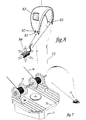
- the SeTAC will be mounted aboard of the kite and powered with flexible solar panel [83]; a little and light accumulator [82] will provide the transmission and sensor power supply energy, even nighttime.
- the self-powering is also required to avoid conductive paths for electrostatic atmospheric charge between the altitude air masses and the ground.
- the KiWiGen's sensors will 'feel' the location of the kites in the sky in order to modify their position, angle and tension, enabling them to engulf the greatest wind force.
- the Kite steering unit is the subassembly composed by the high strength actuators [41], the high speed actuators [52], the numerical control completed by the control software, and a frame hosting these components.
- Several KSUs hosted in the pivotal centre [19] will become components in the wider embodiment called Carousel [fig. 1].
- the kite generator controller acquires the skill and copies the behaviour of a trained person driving acrobatic kites.
- This result will be achieved mainly by an analytical approach means that the system is described and controlled by a set of specially designed algorithms, providing feedback on the lines through the winch/reels [41], on the basis of the data collected by the sensors,
- This software can be scaled at different levels of coding difficulty and efficiency in exploiting the wind. On one side, an easier coding can behave in conservative mode, by improving the operational determinism. On the other side, the software complexity can be forced towards acrobatic performance, thereby improving the energy collection attitude.
- the computing power available in current microprocessors can support every level of real time software complexity and resource demands; certainly enough to outperform humans in providing fast and calibrated retro-actions.
- the kite generator KSU has a functional diagram very similar to that of an industrial machine. It can use standard components of the technology employed in the realisation of the electromechanical group, including servo-drives, servomotors and encoders.
- the typical electronic hardware that controls all the component chain is a multi axial numerical control.
- the numerical control could be supported by an additional computing capability to perform the real-time three dimensional model emulation of the kite in airspace.
- the running software model drives the KiWiGen physical behaviour through the numerical control.
- the KSU modifying the traction/force balance on the kite lines, will implements the kite steering capability.
- the kites in particular in the tandem assemblies, excerpt a traction that could be in the mega Newton range, the steering unit deal with this force trough a primary winch [41] with such torque capability. But a reduction gear with that performance greatly reduces the actuation speed, which sometimes is required for fast reaction to wind gust or for emergency retraction.
- Two subsystems provide the fast actuation for the two situations: the passive counterweight actuator [42] for the wind fast adaptive control and the in series lower force high-speed winch for the fast retraction or to glide home the kites [fig. 3].
- the Passive counterweight is the lines tension/force passive stabilizer obtained by a suspended counterweight [42] and a series of de-multiplying pulley [43] to amplify the running extension of the kite lines, compared to the counterweight vertical and gravitational translation.
- the weight of this device is proportional to the maximum force expected by the kites multiplied by the number of the de-multiplying pulleys [44].
- the primary winch [41] acts in series with the secondary winch [52], that is uniquely used for reeling-in the kites' lines in fast mode, useful for emergency retraction or to glide home the kites [fig. 3].
- the primary winch has a one-way rotation clutch that controls with great force the reeling-out of the lines and makes free the retraction actuated by the secondary winch.
- the KiWiGen Carousel generator is a horizontal circular tensor-structure turning on a vertical axis [53], whose pivotal centre [19] is geared with a conventional alternator [20].
- KiWiGen KSUs control the kite tandems [12] linked to the peripheral edge [14].
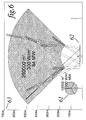
- the carousel embodiment overcomes any limitation that could be imposed to the whole generator size. Kites sweep large sections of the wind front by increasing the energy collection area [fig. 6]. In order to reach an installed power of about one GigaWatt (like the one provided by a medium sized nuclear power plant), the diameter of the frame has to be about one thousand meters.
- the construction challenge is similar to the constructions managed by the civil engineering technologies. More, the territorial impact can be reduced by offshore installations. In any case a comparison with the current windmills states that the territory occupation is 200 times less for the Carousel.
- Kites are retired from wind and they could be accessed for maintenance, substitutions etc.
- the elevation of the peripheral edge of the carousel is dimensioned to make easy and economical the construction and allow at least one kite suspended at the nozzle [14] without touching the ground [fig. 3].
- the topmost kite could extract, thanks to the wind force, the other kites from the carousel frame, then when all the train is flying they could reach the operating position in the sky [13].
- the carousel can supplement the kite's automatic take-off phase even in conditions of low ground wind with a grid powered rotation that procures tangential apparent wind enough to start the take off of the kites, thus reaching a productive altitude.
- each kite array follows a complex path in the sky, kites run at a speed that is much higher than the Carousel tangent edge or the nozzles [14] that are the kites lines outlet.
- the developed path could be several times the circumference of the carousel.
- This feature gives to control a great freedom to choose instant after instant the most productive angles between the kites and the wind.
- the position of the passive counterweight actuator [42] is totally controlled by the kites.
- the counterweight actuator is also the energy reserve to allow a stable kites navigation not only in case of turbulence but also in directions against the wind. This feature optimally administrated by the control allows rapid inversions of direction.
- the KiWiGen carousel could be dimensioned for relatively small plants to very large scale application with minor adaptations. It is possible to build a system with an arbitrary number of kites or kites in tandem assemblies, the area of each wing can vary form few to hundred of square meters without loosing the kite's control capability.
- the lightweight of the flying structure provides the flexibility to handle local turbulence.
- the intercepted wind front can easily reach an area of a million of square meters with a specific architecture and feasible, quite ordinary structures.
- the KiWiGen can be optimised to fulfil the requirement regulating the number of kites in a tandem, the size of the kites, the sweeping speed, the number of tandem concurrently operative on the Carousel frame.
- the KiWiGen can operate either in offshore and onshore installations, typically the ground wind is stronger on the sea, it is expected that this will affect only the take off procedure because when the kites reach the operating altitude the difference between the ground and the altitude wind is slight.
- the KiWiGen could have a useful effect on local weather, in the two extreme situations fog and violent storm.
- the former is a situation of null wind at the ground level.
- the Betz law explains that the wind stream behind the turbine is affected by an increased front size this could be exploited by the KiWiGen to bring some altitude wind at the ground level providing the opportunity to clean from the fog wide territory.
- Fig. 4 A perspective view of the KSU kite steering unit
- Fig. 6 Comparison between equivalent total weight windmill and KiWiGen.
- the hatching represents the windfront.
- Fig. 8 The kite with the onboard instrumentation and power supply
- the aerial part of the kite generator composed by the ultra light wings and lines, can reach heights of a thousand of meters. This could produce some concerns about the safety of the whole system.
- the prototype will be useful for exploring in depth all the relevant aspects, but several questions and consideration can be foreseen in advance and many possible answers are already available.
- the traction cables can supply on the ground site the angular position, whereas the reel encoder can provide the distance of the kite, by making available an alternative position data source.
- Risk - Failures during the flight may take place, for example during the software development, testing and validation phases.
- Solution - An automatic clutch disjoint system can be integrated on one cable only in order to deflate kite and be operated wireless. This system can work even in tandem assemblies.
- Risk - Motor power and/or speed may result inadequate to face strong wind by issuing the reaction on time
- Solution - the control capabilities achieved through elaboration of the input signal provided by the sensors allow rewinding the lines fast enough to glide the kite home.
- Solution - The control allows for more speed in reeling out the lines, in order to reduce the apparent wind acting on the kite.
- Solution ⁇ The control scans the sky with radar and, in case of collision route, rewinds the kite to a safe altitude in a few seconds
- the KSU in particular the kite lines could be subject to vandalism and/or terrorist attacks.
- the maximum force applied on each of the 40 cables is about 100 tons. That means a diameter of 20mm and a cable weight of 300 Kg per Km.
- Each tandem kites assemblies have to exert a traction of 200 tons, which means, by considering a tandem composed of 10 kites, 20 tons applied by each kite.
- a wind of 10m/s that is the European medium value at 1500mt of altitude, contains about 1kW per square meter. Assuming an efficiency factor of 40% and a sweep wind front surface of 1 square kilometre, the power generated could be 400MegaWatt.
- the harnessed power can rise to 3 Gigawatt, against a total wind inertial power of 8 Gigawatt.
- the smart and adaptive control for steering and manoeuvre kites or airfoils will be capable of freely-driving a series of power kites transferring the traction on frames and mechanism trough lines, in order to convert the wind energy into RES.
Landscapes
- Engineering & Computer Science (AREA)
- Mechanical Engineering (AREA)
- Sustainable Development (AREA)
- Sustainable Energy (AREA)
- Chemical & Material Sciences (AREA)
- Combustion & Propulsion (AREA)
- Life Sciences & Earth Sciences (AREA)
- General Engineering & Computer Science (AREA)
- Aviation & Aerospace Engineering (AREA)
- Wind Motors (AREA)
- Control Of Position, Course, Altitude, Or Attitude Of Moving Bodies (AREA)
- Toys (AREA)
- Automatic Cycles, And Cycles In General (AREA)
Abstract
The kite (12) or airfoil automatic steering via cables (11) allows to manoeuvre the kite in different combinations of troposphere altitudes and directions, obtaining full power traction phases in specific direction, phases of stall with rewinding, and gliding phases even against the wind. The traction and the active mechanical energy are transferred to a carousel generator (18,19).
The automatic steering logic is realized through the interface of servo actuators and sensors elements on the kites. Sensor information is continually updated to perform the decision-making and feedback control on the kite attitude and position in order to obtain precise and reliable manoeuvring.
Description
- This application claims priority from IT provisional
application N.TO2003A000945 26/11/2003 - The field of this invention relates to devices that convert the wind energy, more specifically a device that control flying/gliding structures linked trough lines on ground frame that convert the mechanical energy typically in electrical.
-
Patent no. Publication date: Inventor: US3924827 1975-12-09 LOIS LAMBROS US3987987 1976-10-26 MCCUTCHEN CHARLES; PAYNE PETER R US4076190 1978-02-28 LOIS LAMBROS US4124182 1978-11-07 LOEB ARNOLD US4251040 1981-02-17 LOYD MILES L US4659940 1987-04-21 SHEPARD DAVID H (US) CN1052723 1991-07-03 XIAOQUAN LIU (CN) US5056447 1991-10-15 LABRADOR GAUDENCIO A (US) US5533694 1996-07-09 CARPENTER HOWARD G (US) US5931416 1999-08-03 CARPENTER HOWARD G (US) US6072245 2000-06-06 OCKELS WUBBO JOHANNES (NL) US6254034 2001-07-03 CARPENTER HOWARD G (US) US6523781 2003-02-25 RAGNER GARY DEAN (US) - These entire patents disclose devices for collecting altitude wind energy using airfoil, kites, gliders etc.
- The older and most relevant patent explaining the opportunity to harness energy from altitude wind trough kites or airfoils could be the US3987987 MCCUTCHEN PAYNE, which depicts the preliminary idea, and then several evolutions are possible. Some patent describe method exploiting the airfoil drag force, other (US6523781 Ragner) claims that the lift force is higher and also higher the collectable energy density.
- The applicant avoids claiming features of the airfoil or kite physics, which are already fully disclosed in the aeronautical and windmill science.
- The present patent can be considered similar in the sense that the keywords are the same: wind, airfoils, energy etc., but it propose and claims a specific and originally designed machine complete of detailed solution that can lead directly to a new category of exploitable wind generator.
- The applicant agrees the general principles enough disclosed by the previous works and patents.
- The US6072245 Ockels patent, is qualitatively similar to this patent, it go in detail describing the whole and specific wind harnessing machine that could lead to an exploitation. The Ockels machine is different by the one described in the present applicant invention and also the features and functioning characteristics are different.
- For these reason this chapter of prior art will not compare the existing patents or the prior art with the present invention, considering the present invention is yet another wind machine, with a new and original approach to realize an high altitude wind, harnessing machine.
- Therefore it is clear that the applicant is disclosing specific harnessing machine, which was never claimed by other patents. In some cases the other and previous patent referrers to a not better-defined ground station, which is the main interest of the applicant.
- KiWiGen is focused on the development of a troposphere wind generator, hereafter called kite wind generator KiWiGen. The concept is quite simple, as are all truly imaginative ideas: to take advantage of the astounding force of the wind by developing a new method to capture it, which would entrap a far greater quantity, than the present day windmills. To do this one must attain a much higher altitude, reaching the winds that blow continually and reliably several hundred meters above sea level. The means is a series of wide kites, somewhat similar to gliders, which are linked one above another in tandem. Thrust across the horizon in a huge arc, they act as a net. In this manner they trap a vastly larger wind front than the mills of a conventional wind farm.
- Moreover, it is necessary to control the kites, so that they are always flying in a manner that best captures the varying intensity and direction of the wind. This is where the applicant has developed the hypothesis. The applicant realized that their proprietary Tri-Axial Acceleration Computers, (SeTAC) which they have designed and manufactured for three years for purposes of industrial automation and avionic applications, could be used as the groundwork for a three-dimensional control system. The KiWiGen's sensors will 'feel' the location of the kites in the sky and modify their position, angle and tension, enabling them to engulf the greatest wind force. Another major breakthrough is in the physical design of the system. The kite arrays are mounted on a moving frame resembling a Carousel. This circular tensor structure rotates around a vertical axis, whose pivotal centre is geared with a conventional alternator. In effect, it is a very lightweight, giant merry-go-round, 'powered' by the kites strung in tandem, up to an altitude several times higher than the conventional windmills. At this height, in optimum conditions, the kites can reach a speed that allows realising a lift-harnessing machine instead of a drag machine.
- As the wind lifts and thrusts the kites into the wild blue yonder, the kite arrays come into contact with a much greater volume of wind. The Carousel system should be able to generate an amount of electrical energy equivalent to the output of an entire conventional power plant, unimaginable by other methods.
- The KiWiGen will deal with more interdisciplinary aspects, i.e. the wind and airfoils aerodynamics plus sophisticated control mechatronics.
- For the wind and airfoils aerodynamics part, the applicant assumes that the research and consequently the market already offer special kites. They are categorised as power kites with an important background of included research and characteristics, which are suitable for this implementation as component. Consequently, the patent is mainly focused on the description of the control apparatus, which can be conceptually divided in sensor systems, actuation hardware on the ground and at the kite, plus the controlling software.
- A special set of wind self-powered sensors; such as the tri-axial accelerometers/inclinometers is the kite's onboard equipment in wireless connection with the KSU [fig 4].
- From the hardware point of view, part of the technology is borrowed from the robotics field, by deeply exploiting servo motors-drives and numerical controls.
- The Kite [31] is the interface between the natural wind energy and the harnessing machine.
- By capturing the wind kinetic energy, kites are able to supply a massive quantity of mechanical energy, which comes from the traction force exerted on the cable [11], and multiplied by kite's arbitrary displacement. Thanks to the latest aerodynamic studies and applications, kites can provide particular features in terms of manoeuvrability and control, while the energy transferred from the wind can be modulated due to the kite manoeuvrability. Specific diagrams depict the maximum power and the stall areas of the kite in relation to the wind. Therefore, by steering the kite appropriately, it is possible to navigate the airspace modulating the condition of maximum power of traction and the directions
- Kites could be assembled in tandem arrays [12] in order to improve the total airfoil area.
- One of the most important KiWiGen breakthrough is the two wire kite steering and the absence of any kind of mechanism in the flying structure; thanks to the control strategy the kite attitude control is unnecessary.
- The applicant's patented Tri-Axial Acceleration Computers (SeTAC) [84] which has been designed and manufactured for many years for purposes of industrial automation and avionic applications, can be used as the groundwork for a three-dimensional control system. A special version of self-powered SeTAC [81], such as the tri-axial accelerometer/inclinometer, is the kite's onboard equipment in wireless connection with the KSU [fig. 4].
- The SeTAC will be mounted aboard of the kite and powered with flexible solar panel [83]; a little and light accumulator [82] will provide the transmission and sensor power supply energy, even nighttime.
- The self-powering is also required to avoid conductive paths for electrostatic atmospheric charge between the altitude air masses and the ground.
- The KiWiGen's sensors will 'feel' the location of the kites in the sky in order to modify their position, angle and tension, enabling them to engulf the greatest wind force.
- The Kite steering unit is the subassembly composed by the high strength actuators [41], the high speed actuators [52], the numerical control completed by the control software, and a frame hosting these components. Several KSUs hosted in the pivotal centre [19] will become components in the wider embodiment called Carousel [fig. 1].
- It is the core that makes feasible the invention and must be built with perception-based decision making, motion and force modelling of the kite in the airspace. An analytical approach is adopted to set-up the special algorithms. Remote interfacing of the numerical control is the main feature on which the method for setting-up the knowledge and the ability for automatic kiting is based.
- This knowledge is comprehensive of a correct reaction to unforeseen events and to natural wind variations this ability will be empowered by a special mechanical feature of the KSU that implement a kite force counterweight [42] in order to stabilise all the physic parameter involved in the kite steering.
- The kite generator controller acquires the skill and copies the behaviour of a trained person driving acrobatic kites. This result will be achieved mainly by an analytical approach means that the system is described and controlled by a set of specially designed algorithms, providing feedback on the lines through the winch/reels [41], on the basis of the data collected by the sensors, This software can be scaled at different levels of coding difficulty and efficiency in exploiting the wind. On one side, an easier coding can behave in conservative mode, by improving the operational determinism. On the other side, the software complexity can be forced towards acrobatic performance, thereby improving the energy collection attitude. In any case, the computing power available in current microprocessors can support every level of real time software complexity and resource demands; certainly enough to outperform humans in providing fast and calibrated retro-actions.
- The kite generator KSU has a functional diagram very similar to that of an industrial machine. It can use standard components of the technology employed in the realisation of the electromechanical group, including servo-drives, servomotors and encoders. The typical electronic hardware that controls all the component chain is a multi axial numerical control.
- The numerical control could be supported by an additional computing capability to perform the real-time three dimensional model emulation of the kite in airspace. The running software model drives the KiWiGen physical behaviour through the numerical control.
- The KSU, modifying the traction/force balance on the kite lines, will implements the kite steering capability. The kites, in particular in the tandem assemblies, excerpt a traction that could be in the mega Newton range, the steering unit deal with this force trough a primary winch [41] with such torque capability. But a reduction gear with that performance greatly reduces the actuation speed, which sometimes is required for fast reaction to wind gust or for emergency retraction. Two subsystems provide the fast actuation for the two situations: the passive counterweight actuator [42] for the wind fast adaptive control and the in series lower force high-speed winch for the fast retraction or to glide home the kites [fig. 3].
- The Passive counterweight is the lines tension/force passive stabilizer obtained by a suspended counterweight [42] and a series of de-multiplying pulley [43] to amplify the running extension of the kite lines, compared to the counterweight vertical and gravitational translation.
- In case of wind gust or instant wind absence this device react properly maintaining the force on the lines for enough time to make the whole system insensitive to the event or allowing the active actuator to drive the proper reaction in time.
- The weight of this device is proportional to the maximum force expected by the kites multiplied by the number of the de-multiplying pulleys [44].
- The primary winch [41] acts in series with the secondary winch [52], that is uniquely used for reeling-in the kites' lines in fast mode, useful for emergency retraction or to glide home the kites [fig. 3]. The primary winch has a one-way rotation clutch that controls with great force the reeling-out of the lines and makes free the retraction actuated by the secondary winch.
- This function could be even obtained by a multi speed geared winch, but the extreme difference of the two situations makes unpractical the adoption of such device.
- The KiWiGen Carousel generator is a horizontal circular tensor-structure turning on a vertical axis [53], whose pivotal centre [19] is geared with a conventional alternator [20]. Several KiWiGen KSUs control the kite tandems [12] linked to the peripheral edge [14]. The carousel embodiment overcomes any limitation that could be imposed to the whole generator size. Kites sweep large sections of the wind front by increasing the energy collection area [fig. 6]. In order to reach an installed power of about one GigaWatt (like the one provided by a medium sized nuclear power plant), the diameter of the frame has to be about one thousand meters. However, the construction challenge is similar to the constructions managed by the civil engineering technologies. More, the territorial impact can be reduced by offshore installations. In any case a comparison with the current windmills states that the territory occupation is 200 times less for the Carousel.
- The most important feature of the Carousel is the capability to host the retracted kites even in tandem array directly in Carousel frame. Kites are retired from wind and they could be accessed for maintenance, substitutions etc.
- The elevation of the peripheral edge of the carousel is dimensioned to make easy and economical the construction and allow at least one kite suspended at the nozzle [14] without touching the ground [fig. 3].
- An actual breakthrough of the applicant invention is the opportunity to realise a totally automatic or remote controlled power plant. In condition of stand-by when the kite tandem assembly is retired into the frame [fig. 3], the topmost kite could be exposed to the breeze waiting for enough wind to start the procedure of launch.
- The topmost kite could extract, thanks to the wind force, the other kites from the carousel frame, then when all the train is flying they could reach the operating position in the sky [13].
- The carousel can supplement the kite's automatic take-off phase even in conditions of low ground wind with a grid powered rotation that procures tangential apparent wind enough to start the take off of the kites, thus reaching a productive altitude.
- When the topmost kite is exposed to the breeze in the stand-by situation could happen that the slight and disordered wind act forces to twist the lines of the fallen and suspended kite, but also in this situation the kite position is measured by the sensors and then controlled by the feedback loop.
- During the operativity each kite array follows a complex path in the sky, kites run at a speed that is much higher than the Carousel tangent edge or the nozzles [14] that are the kites lines outlet. The developed path could be several times the circumference of the carousel. This feature gives to control a great freedom to choose instant after instant the most productive angles between the kites and the wind. In this phase the position of the passive counterweight actuator [42] is totally controlled by the kites. The counterweight actuator is also the energy reserve to allow a stable kites navigation not only in case of turbulence but also in directions against the wind. This feature optimally administrated by the control allows rapid inversions of direction. Running most time in one direction on the beam followed by a fast gybe then on the beam in the opposite direction followed by a tack manoeuvre and again from the beginning composes the more productive path (on the beam, gybe, tack are corresponding nautical navigation terms).
- In the airspace kites have one more dimension available than the nautical equivalent navigation.
- The KiWiGen carousel could be dimensioned for relatively small plants to very large scale application with minor adaptations. It is possible to build a system with an arbitrary number of kites or kites in tandem assemblies, the area of each wing can vary form few to hundred of square meters without loosing the kite's control capability.
- It is not required to over-dimension the components to gain a security margin and unnecessary fatigue resistance, because in case of impulsive strong winds the KiWiGen KSU react reeling out the lines, thereby reducing the apparent wind acting on the wing. The lightweight of the flying structure provides the flexibility to handle local turbulence. The intercepted wind front can easily reach an area of a million of square meters with a specific architecture and feasible, quite ordinary structures. According to the Betz law the maximum power subtracted to the wind is attained braking the air mass to 1/3 of the it original speed; the KiWiGen can be optimised to fulfil the requirement regulating the number of kites in a tandem, the size of the kites, the sweeping speed, the number of tandem concurrently operative on the Carousel frame.
- The KiWiGen can operate either in offshore and onshore installations, typically the ground wind is stronger on the sea, it is expected that this will affect only the take off procedure because when the kites reach the operating altitude the difference between the ground and the altitude wind is slight.
- The KiWiGen could have a useful effect on local weather, in the two extreme situations fog and violent storm. The former is a situation of null wind at the ground level. The Betz law explains that the wind stream behind the turbine is affected by an increased front size this could be exploited by the KiWiGen to bring some altitude wind at the ground level providing the opportunity to clean from the fog wide territory.
- In the other case with very strong wind like during tornados the KiWiGen can deal with the gigantic power choosing a set smaller and faster kites.
- These storm kites will maintain the manoeuvrability even in extreme situations. The continuous wind power subtraction operated by the KiWiGen could be in the order of magnitude of the storm giving a great opportunity to rescue the involved lands.
-
- 11
- steering/power lines or cables
- 12
- Kites in tandem array
- 13
- Kites path in airspace
- 14
- Carousel nozzles
- 15
- Suspension cable
- 16
- Carousel arm, an element of the stellar frame
- 17
- Brace cables. The kite's forces are mainly discharged on these cables that impress the rotation power to the central pivot
- 18
- Carousel tower is the column sustaining all the suspension cables
- 19
- Central Pivot fulfils the functions of support-bearing for the whole system and hosts the gearing to the electrical generator or alternator
-
- 25
- Bearing allowing the radial rotation of the pulley
- 26
- Birotative Pulley following lines slant
- 27
- Man silhouette as evidence for dimensions and accessibility
-
- 31
- Topmost kite exposed to the breeze waiting for takeoff
-
- 41
- High force winch
- 42
- Counterweight
- 43
- Pulley
- 44
- De-multiplying pulleys set
- 45
- Steering power lines to the nozzle and than to the kite array
-
- 51
- drawing snip implying arm lenght
- 52
- high-speed winches/actuators
- 53
- Rotation axis
-
- 61
- conventional windmill
- 62
- KiWigen Carousel front view
- 63
- Altitude scale
-
- 71
- Pictorial drawing
- 72
- Basement
- 73
- Rotating table
- 74
- Brushless motor
- 75
- Reel
- 76
- Lines directly to kite
-
- 81
- Radio inclinometer/accelerometer SeTAC
- 82
- Accumulator
- 83
- Flexible photovoltaic solar panel
- 84
- SeTAC enlargement
- The aerial part of the kite generator, composed by the ultra light wings and lines, can reach heights of a thousand of meters. This could produce some concerns about the safety of the whole system. The prototype will be useful for exploring in depth all the relevant aspects, but several questions and consideration can be foreseen in advance and many possible answers are already available.
- Risk - The tests reveals a generic lack in the design or in the device's expected functionality.
- Solution - The partners are confident that all project assumptions are realistic. However, the KiWiGen project is not impotently safeguarded from the risks of failure or unforeseen factors taking place. In the case that this unlikely event occurs, investigation will be aimed at identifying the sources of the problem and prompt corrective actions will be studied in order to avoid a delay in meeting the project objectives.
- Risk - Current legislation does not allow for occupying the airspace for testing the demonstrator, and the competent authority does not provide special licenses.
- Solution ― The prototype will be tested in aerostatics and stratosphere balloon ground-fields and in occasion of wind manifestations. Whether the results gained comply with present expectations, inputs and proposals for new regulatory measures will be provided. At present a test area in the north of the Netherlands is available, including the support of the local authorities, allowing for tests up to several hundreds of meters.
- Risk - The sensors, as well as the inertial platforms, have to provide all the information on acceleration, velocity and position of the kites in airspace. The measurement precision may result inadequate due to the required mathematical signal integration.
- Solution - The traction cables can supply on the ground site the angular position, whereas the reel encoder can provide the distance of the kite, by making available an alternative position data source.
- Risk - Failures during the flight may take place, for example during the software development, testing and validation phases.
- Solution - An adequate number of sensors will be employed in order to always have backup devices in case of abnormal functioning and to ensure the full control of the system. Any problem will be already detected during the second phase of the instrumental flight
- Risk ― Wireless communication between the kite and the KSU does not work due to the distance Solution ― Different ways for communication will be studied (through VHF radio, cable, laser...)
- Risk - Safety issues can be raised by the cables. They are the components in which all the wind force is concentrated. During an anomalous ground sweep they could hit persons and objects.
- Solution - An automatic clutch disjoint system can be integrated on one cable only in order to deflate kite and be operated wireless. This system can work even in tandem assemblies.
- Risk - Motor power and/or speed may result inadequate to face strong wind by issuing the reaction on time
- Solution ― The employment of different and more powerful motors will be considered.
- Risk ― The wing and the lines could fall down onto neighbour's lands, due to the absence of wind
- Solution - the control capabilities achieved through elaboration of the input signal provided by the sensors allow rewinding the lines fast enough to glide the kite home.
- Risk- the wind could be so strong as to stretch or tear a line.
- Solution - The control allows for more speed in reeling out the lines, in order to reduce the apparent wind acting on the kite.
- Risk ― a plane or a helicopter could collide with the wings or the lines
- Solution ― The control scans the sky with radar and, in case of collision route, rewinds the kite to a safe altitude in a few seconds
- Risk - The KSU, in particular the kite lines could be subject to vandalism and/or terrorist attacks.
- Solution - Some of the embodiments presented could make the moving parts inaccessible.
- The extraordinary features of the recently developed cables (such as Dyneema®) offer the missing link needed to achieve the Gigawatt power: an example of which could be roughly some 40 MN (4000 tons) applied tangentially on the carousel generator at a speed of 25m/s.
- By considering a system with 20 kites in tandem assemblies, the maximum force applied on each of the 40 cables is about 100 tons. That means a diameter of 20mm and a cable weight of 300 Kg per Km. Each tandem kites assemblies have to exert a traction of 200 tons, which means, by considering a tandem composed of 10 kites, 20 tons applied by each kite.
- Therefore, a wind of 10m/s, that is the European medium value at 1500mt of altitude, contains about 1kW per square meter. Assuming an efficiency factor of 40% and a sweep wind front surface of 1 square kilometre, the power generated could be 400MegaWatt.
- Assuming a stronger wind with a 20m/s (70 km/h not rare in altitude) speed value as the power generated varies with the cube of the wind speed, the harnessed power can rise to 3 Gigawatt, against a total wind inertial power of 8 Gigawatt.
- Everyone who approaches this new wind generator concept for the first time is fascinated and amused by the new perspective. However, everything becomes tremendously serious when a rough evaluation of the cost per installed Watt is performed and compared to the other power sources.
- First calculations show that the investment cost is approximately 100 times lower than the one necessary for conventional generation plants. A comprehensive technical and economical documentation will be produced to verify the project premises and offer all the decision making tools for the project follow-up.
- The applicant considers to have disclosed a new method to produce renewable energy, then a system to convert the kinetic wind or ocean energy that is alternative innovative and outperform the traditional system. In the development of this system the applicant claim:
- The smart and adaptive control for steering and manoeuvre kites or airfoils, it will be capable of freely-driving a series of power kites transferring the traction on frames and mechanism trough lines, in order to convert the wind energy into RES.
Claims (8)
- The ideation and the concept of the embodiment called kite steering unit and its features, which is the core component of a wider system suitable to harness energy from wind or ocean stream. characterised by a mix of passive and active actuation capabilities
- The concept to realize a wind harnessing system characterised in that the primary functioning scheme is obtained by soft-automation capable to fully act in sensing feedback in order to stabilise and modulate the behaviour and the managed power.
- The ideation and the application of the self-powered tri-axial inclinometer on the flying structure used as five axis sensor using the gravity acceleration as reference characterised by allowing the smart control of power kites transmitting to the kite steering unit the data in wireless mode.
- The ideation and the application on the kite steering unit of the tension/force passive stabilizer on the lines characterised by a suspended counterweight and a series of de-multiplying pulley to amplify the running extension of the kite lines compared to the counterweight translation.
- The ideation and the concept of the embodiments called Kite Wind Generator Carousel; characterised in that the kite arrays are mounted tangentially on the moving frame. This circular tensor structure rotates around a vertical axis, whose pivotal centre is geared with a conventional alternator. In effect, it is a very light weight, giant merry-go-round, 'powered' by the kites.
- The ideation and the concept of the embodiment called train generator characterised in that the frame is dragged alternatively in linear mode or on a circular path powered by the kites controlled by the smart control. The relative motion between the rail and the convoy is geared to the electrical generator.
- The ideation of a method characterised by concentrating important amounts of dispersed wind energy into a single generation plant setting-up the optimised path of the kites in airspace and intercepting high altitude wide wind front.
- All The embodiments characterised by a low barycentre or centre of gravity, with the heavy structures and frames near to the ground and the ultra-light aerial part that can reach hundred of meter without changing the centre of gravity. This characteristic allows systems with huge dimensions.
Priority Applications (5)
| Application Number | Priority Date | Filing Date | Title |
|---|---|---|---|
| EP04028646A EP1672214B1 (en) | 2004-12-03 | 2004-12-03 | Vertical axis wind turbine with control system steering kites |
| DE602004012128T DE602004012128T2 (en) | 2004-12-03 | 2004-12-03 | Wind turbine with vertical axis of rotation with a control system for kites |
| PL04028646T PL1672214T3 (en) | 2004-12-03 | 2004-12-03 | Vertical axis wind turbine with control system steering kites |
| AT04028646T ATE387581T1 (en) | 2004-12-03 | 2004-12-03 | WIND TURBINE WITH VERTICAL AXIS OF ROTATION WITH A KITE CONTROL SYSTEM |
| ES04028646T ES2301919T3 (en) | 2004-12-03 | 2004-12-03 | VERTICAL SHAFT WIND TURBINE WITH CONTROL SYSTEM FOR STEERING COMET. |
Applications Claiming Priority (1)
| Application Number | Priority Date | Filing Date | Title |
|---|---|---|---|
| EP04028646A EP1672214B1 (en) | 2004-12-03 | 2004-12-03 | Vertical axis wind turbine with control system steering kites |
Publications (2)
| Publication Number | Publication Date |
|---|---|
| EP1672214A1 true EP1672214A1 (en) | 2006-06-21 |
| EP1672214B1 EP1672214B1 (en) | 2008-02-27 |
Family
ID=34927633
Family Applications (1)
| Application Number | Title | Priority Date | Filing Date |
|---|---|---|---|
| EP04028646A Expired - Lifetime EP1672214B1 (en) | 2004-12-03 | 2004-12-03 | Vertical axis wind turbine with control system steering kites |
Country Status (5)
| Country | Link |
|---|---|
| EP (1) | EP1672214B1 (en) |
| AT (1) | ATE387581T1 (en) |
| DE (1) | DE602004012128T2 (en) |
| ES (1) | ES2301919T3 (en) |
| PL (1) | PL1672214T3 (en) |
Cited By (13)
| Publication number | Priority date | Publication date | Assignee | Title |
|---|---|---|---|---|
| WO2007122650A1 (en) * | 2006-04-24 | 2007-11-01 | Kite Gen Research S.R.L. | Aeolian system comprising power wing profiles and process for producing electric energy |
| WO2008004261A1 (en) * | 2006-07-04 | 2008-01-10 | Massimo Ippolito | Wind system for converting energy thboqgi a vertical-axis turbine actuated by means of kites and process for producing electric energy through soch system |
| WO2010084520A1 (en) | 2009-01-23 | 2010-07-29 | Sequoia Automation S.R.L. | Tether for tropospheric aeolian generator |
| WO2011033545A1 (en) | 2009-09-16 | 2011-03-24 | Ce.S.I. Centro Studi Industriali Di Taddei Simona Maria & C. S.A.S. | Anti-kinking transmission and guiding system for cables |
| ITTO20100258A1 (en) * | 2010-03-31 | 2011-10-01 | Modelway S R L | CONTROL ACTUATION SYSTEMS FOR THE FLIGHT OF A POWER WING PROFILE FOR THE CONVERSION OF WIND ENERGY IN ELECTRIC OR MECHANICAL ENERGY |
| US8100366B2 (en) | 2006-12-11 | 2012-01-24 | Kite Gen Research S.R.L. | Automatic kite flight control system |
| US8152106B2 (en) | 2006-05-10 | 2012-04-10 | Kite Gen Research S.L.R. | System and process for automatically controlling the flight of power wing airfoils |
| EP2672109A1 (en) | 2012-06-04 | 2013-12-11 | moct7.com GbR | System and method for converting wind flow energy into mechanical, thermodynamic or electrical energy |
| EP2682600A1 (en) | 2007-03-30 | 2014-01-08 | Kite Gen Research S.R.L. | Wind energy converter using kites |
| WO2014087436A1 (en) | 2012-12-07 | 2014-06-12 | Kite Gen Research S.R.L. | Wind energy conversion system with kites towing modules on a rail |
| WO2014199406A1 (en) | 2013-06-12 | 2014-12-18 | Kite Gen Research S.R.L. | System and process for starting the flight of power wing airfoils, in particular for wind generator |
| WO2015037027A1 (en) | 2013-09-13 | 2015-03-19 | Kite Gen Research S.R.L. | Tensioning and tension measuring device of at least one rope |
| WO2015037024A1 (en) | 2013-09-13 | 2015-03-19 | Kite Gen Research S.R.L. | Process for managing, adjusting and controlling a wind generator |
Families Citing this family (3)
| Publication number | Priority date | Publication date | Assignee | Title |
|---|---|---|---|---|
| ITTO20110251A1 (en) | 2011-03-23 | 2012-09-24 | Kitenergy S R L | WIND ENERGY CONVERSION SYSTEM IN ELECTRIC ENERGY THROUGH THE FLIGHT OF POWERED WINGED PROFILES LANDED BY FIXED LENGTH CABLES, WITHOUT PASSIVE PHASES AND ADAPTING AUTOMATICALLY TO THE WIND CONDITIONS |
| EP2969921A2 (en) | 2013-03-11 | 2016-01-20 | Saudi Basic Industries Corporation | Renewable energy system for generating hydrogen and hydrogen products |
| DE102016011435B4 (en) * | 2016-09-16 | 2024-02-15 | Harry Martin | Energy supply unit |
Citations (6)
| Publication number | Priority date | Publication date | Assignee | Title |
|---|---|---|---|---|
| US3924827A (en) * | 1975-04-25 | 1975-12-09 | Lambros Lois | Apparatus for extracting energy from winds at significant height above the surface |
| DE2839918A1 (en) * | 1978-09-14 | 1980-03-27 | Erich Herter | Wind driven power turbine unit - has vertical axis rotor holding flying wind vanes above it via tension absorbing cables |
| FR2766241A1 (en) * | 1997-07-15 | 1999-01-22 | Lech Chmielinski | Wind turbine, |
| US6254034B1 (en) * | 1999-09-20 | 2001-07-03 | Howard G. Carpenter | Tethered aircraft system for gathering energy from wind |
| US20030066934A1 (en) * | 2001-09-06 | 2003-04-10 | Bolonkin Alexander Alexandrovich | Method of utilization a flow energy and power installation for it |
| WO2004044418A1 (en) * | 2002-11-13 | 2004-05-27 | Pavel Miodushevsky | Apparatus, plant and method for the conversion of wind or water flow energy into electrical energy |
-
2004
- 2004-12-03 DE DE602004012128T patent/DE602004012128T2/en not_active Expired - Lifetime
- 2004-12-03 EP EP04028646A patent/EP1672214B1/en not_active Expired - Lifetime
- 2004-12-03 PL PL04028646T patent/PL1672214T3/en unknown
- 2004-12-03 AT AT04028646T patent/ATE387581T1/en not_active IP Right Cessation
- 2004-12-03 ES ES04028646T patent/ES2301919T3/en not_active Expired - Lifetime
Patent Citations (6)
| Publication number | Priority date | Publication date | Assignee | Title |
|---|---|---|---|---|
| US3924827A (en) * | 1975-04-25 | 1975-12-09 | Lambros Lois | Apparatus for extracting energy from winds at significant height above the surface |
| DE2839918A1 (en) * | 1978-09-14 | 1980-03-27 | Erich Herter | Wind driven power turbine unit - has vertical axis rotor holding flying wind vanes above it via tension absorbing cables |
| FR2766241A1 (en) * | 1997-07-15 | 1999-01-22 | Lech Chmielinski | Wind turbine, |
| US6254034B1 (en) * | 1999-09-20 | 2001-07-03 | Howard G. Carpenter | Tethered aircraft system for gathering energy from wind |
| US20030066934A1 (en) * | 2001-09-06 | 2003-04-10 | Bolonkin Alexander Alexandrovich | Method of utilization a flow energy and power installation for it |
| WO2004044418A1 (en) * | 2002-11-13 | 2004-05-27 | Pavel Miodushevsky | Apparatus, plant and method for the conversion of wind or water flow energy into electrical energy |
Non-Patent Citations (3)
| Title |
|---|
| ANONYMOUS: "Advanced Hybrid Mechatronic Materials", INTERNET ARTICLE, 25 September 2004 (2004-09-25), XP002343492, Retrieved from the Internet <URL:http://web.archive.org/web/20040925005901/http://sequoiaonline.com/> [retrieved on 20050905] * |
| M. IPPOLITO: "The KIWIgen Project - Kite Wind Generator", INTERNET ARTICLE, XP002343508, Retrieved from the Internet <URL:http://europa.eu.int/comm/research/energy/pdf/other_res_02ippolito.pdf> [retrieved on 20050905] * |
| 'Renewable energy technologies and socio-economic tools infoday' Sheraton Brussels Airport Conference Centre, 19 October 2004 'Wind converters', M. Ippolito * |
Cited By (38)
| Publication number | Priority date | Publication date | Assignee | Title |
|---|---|---|---|---|
| US8080889B2 (en) | 2006-04-24 | 2011-12-20 | Kite Gen Research S.R.L. | Aeolian system comprising power wing profiles and process for producing electric energy |
| WO2007122650A1 (en) * | 2006-04-24 | 2007-11-01 | Kite Gen Research S.R.L. | Aeolian system comprising power wing profiles and process for producing electric energy |
| US8152106B2 (en) | 2006-05-10 | 2012-04-10 | Kite Gen Research S.L.R. | System and process for automatically controlling the flight of power wing airfoils |
| RU2436992C2 (en) * | 2006-07-04 | 2011-12-20 | Массимо ИППОЛИТО | Generation method of electric power by means of wind system |
| US8134249B2 (en) | 2006-07-04 | 2012-03-13 | Massimo Ippolito | Wind system for converting energy through a vertical-axis turbine actuated by means of kites and process for producing electric energy through such system |
| EP2642117A3 (en) * | 2006-07-04 | 2014-05-07 | Kite Gen Research S.R.L. | Wind system for converting energy through a vertical-axis turbine actuated by means of kites and process for producing electric energy through such system |
| EP2642116A3 (en) * | 2006-07-04 | 2014-05-07 | Kite Gen Research S.R.L. | Wind system for converting energy through a vertical-axis turbine actuated by means of kites and process for producing electric energy through such system |
| EP2642118A3 (en) * | 2006-07-04 | 2014-11-05 | Kite Gen Research S.R.L. | Wind system for converting energy through a vertical-axis turbine actuated by means of kites and process for producing electric energy through such system |
| EP2642118A2 (en) | 2006-07-04 | 2013-09-25 | Kite Gen Research S.R.L. | Wind system for converting energy through a vertical-axis turbine actuated by means of kites and process for producing electric energy through such system |
| JP2009542955A (en) * | 2006-07-04 | 2009-12-03 | イッポリート,マッシーモ | Wind system for converting energy in a vertical axis turbine driven by a kite and method for generating electrical energy from the system |
| EP2642119A3 (en) * | 2006-07-04 | 2014-11-05 | Kite Gen Research S.R.L. | Wind system for converting energy through a vertical-axis turbine actuated by means of kites and process for producing electric energy through such system |
| WO2008004261A1 (en) * | 2006-07-04 | 2008-01-10 | Massimo Ippolito | Wind system for converting energy thboqgi a vertical-axis turbine actuated by means of kites and process for producing electric energy through soch system |
| EP2642117A2 (en) | 2006-07-04 | 2013-09-25 | Kite Gen Research S.R.L. | Wind system for converting energy through a vertical-axis turbine actuated by means of kites and process for producing electric energy through such system |
| CN101484694B (en) * | 2006-07-04 | 2012-07-25 | 玛斯莫·爱普力拓 | Wind power system using kite to drive vertical shaft wind turbine for energy conversion and method for generating electric energy using the system |
| EP2642119A2 (en) | 2006-07-04 | 2013-09-25 | Kite Gen Research S.R.L. | Wind system for converting energy through a vertical-axis turbine actuated by means of kites and process for producing electric energy through such system |
| AU2007270703B2 (en) * | 2006-07-04 | 2013-05-23 | Kite Gen Research S.R.L. | Wind system for converting energy through a vertical-axis turbine actuated by means of kites and process for producing electric energy through such system |
| EP2642116A2 (en) | 2006-07-04 | 2013-09-25 | Kite Gen Research S.R.L. | Wind system for converting energy through a vertical-axis turbine actuated by means of kites and process for producing electric energy through such system |
| US8100366B2 (en) | 2006-12-11 | 2012-01-24 | Kite Gen Research S.R.L. | Automatic kite flight control system |
| EP2685091A1 (en) | 2007-03-30 | 2014-01-15 | Kite Gen Research S.R.L. | Wind energy converter using kites |
| EP2682599A1 (en) | 2007-03-30 | 2014-01-08 | Kite Gen Research S.R.L. | Wind energy converter using kites |
| EP2682598A1 (en) | 2007-03-30 | 2014-01-08 | Kite Gen Research S.R.L. | Wind energy converter using kites |
| EP2682600A1 (en) | 2007-03-30 | 2014-01-08 | Kite Gen Research S.R.L. | Wind energy converter using kites |
| US8539746B2 (en) | 2009-01-23 | 2013-09-24 | Kite Gen Research S.R.L. | Tether for tropospheric aeolian generator |
| WO2010084520A1 (en) | 2009-01-23 | 2010-07-29 | Sequoia Automation S.R.L. | Tether for tropospheric aeolian generator |
| JP2013504504A (en) * | 2009-09-16 | 2013-02-07 | チーイ. エッセ. イ. チェントロ ストゥディ インダストリアリ ディ タッデイ シモーナ,マリア エ チー. エッセ. ア. エッセ. | Power transmission guide system with cable tangle prevention function |
| US20120168552A1 (en) * | 2009-09-16 | 2012-07-05 | Ce.S.I. Centro Studi Industrial Di Taddei Simona Maria & C. S.A.S. | Anti-kinking transmission and guiding system for running cables |
| WO2011033545A1 (en) | 2009-09-16 | 2011-03-24 | Ce.S.I. Centro Studi Industriali Di Taddei Simona Maria & C. S.A.S. | Anti-kinking transmission and guiding system for cables |
| US8511645B2 (en) * | 2009-09-16 | 2013-08-20 | Ce.S.I. Centro Studi Industriali Di Taddei Simona Maria & C. S.A.S. | Anti-kinking transmission and guiding system for running cables |
| RU2576396C2 (en) * | 2010-03-31 | 2016-03-10 | Китэнерджи С.Р.Л. | Actuators for control over flight of structural profile of wing for conversion of wind energy into electric or mechanical power |
| ITTO20100258A1 (en) * | 2010-03-31 | 2011-10-01 | Modelway S R L | CONTROL ACTUATION SYSTEMS FOR THE FLIGHT OF A POWER WING PROFILE FOR THE CONVERSION OF WIND ENERGY IN ELECTRIC OR MECHANICAL ENERGY |
| WO2011121557A3 (en) * | 2010-03-31 | 2011-12-08 | Kitenergy S.R.L. | Actuating systems for controlling the flight of a power wing profile for conversion of wind energy into electrical or mechanical energy |
| US9366225B2 (en) | 2010-03-31 | 2016-06-14 | Kitenergy S.R.L. | Actuating systems for controlling the flight of a power wing profile for conversion of wind energy into electrical or mechanical energy |
| WO2013182988A2 (en) | 2012-06-04 | 2013-12-12 | Moct7.Com Gbr | System and method for converting fluid flow energy into mechanical, thermodynamic or electrical energy |
| EP2672109A1 (en) | 2012-06-04 | 2013-12-11 | moct7.com GbR | System and method for converting wind flow energy into mechanical, thermodynamic or electrical energy |
| WO2014087436A1 (en) | 2012-12-07 | 2014-06-12 | Kite Gen Research S.R.L. | Wind energy conversion system with kites towing modules on a rail |
| WO2014199406A1 (en) | 2013-06-12 | 2014-12-18 | Kite Gen Research S.R.L. | System and process for starting the flight of power wing airfoils, in particular for wind generator |
| WO2015037027A1 (en) | 2013-09-13 | 2015-03-19 | Kite Gen Research S.R.L. | Tensioning and tension measuring device of at least one rope |
| WO2015037024A1 (en) | 2013-09-13 | 2015-03-19 | Kite Gen Research S.R.L. | Process for managing, adjusting and controlling a wind generator |
Also Published As
| Publication number | Publication date |
|---|---|
| ATE387581T1 (en) | 2008-03-15 |
| EP1672214B1 (en) | 2008-02-27 |
| ES2301919T3 (en) | 2008-07-01 |
| DE602004012128T2 (en) | 2009-03-19 |
| PL1672214T3 (en) | 2008-09-30 |
| DE602004012128D1 (en) | 2008-04-10 |
Similar Documents
| Publication | Publication Date | Title |
|---|---|---|
| EP1672214B1 (en) | Vertical axis wind turbine with control system steering kites | |
| Fagiano et al. | High-altitude wind power generation | |
| Cherubini et al. | Airborne Wind Energy Systems: A review of the technologies | |
| US9109575B2 (en) | Flying electric generators with clean air rotors | |
| US8602363B2 (en) | Power generating kite system | |
| US8066225B1 (en) | Multi-tether cross-wind kite power | |
| Khan et al. | Harnessing airborne wind energy: Prospects and challenges | |
| EP1952016A1 (en) | A wind turbine | |
| KR102089562B1 (en) | Inspection Method For Wind Generator Using Drone | |
| Lansdorp et al. | Modeling, simulation, and testing of surf kites for power generation | |
| JPH02275100A (en) | Flying generating device | |
| Lansdorp et al. | The laddermill-innovative wind energy from high altitudes in holland and australia | |
| US20100001534A1 (en) | Electric Power Generation System Using Hydro Turbine Tracted by Paraglider | |
| Gulabani et al. | Review on Unconventional Wind Energy. | |
| Oliveira | Airborne wind energy with tethered wings: modeling, analysis and control | |
| Roberts | Quad-rotorcraft to harness high-altitude wind energy | |
| Abbate et al. | What else is emerging from the horizon? | |
| Schmehl | Kiting for wind power | |
| Lansdorp et al. | Towards flight testing of remotely controlled surfkites for wind energy generation | |
| JP7138220B2 (en) | Apparatus for extracting power from a fluid stream | |
| Nam et al. | High Altitude Aerial Platform" Mothership" Project Vision and Progress | |
| Zhang | Kite modeling for higher altitude wind energy | |
| Ahrens | Airborne Wind Energy: An Overview of the Technological Approaches | |
| Gupta | Magnus based airborne wind energy systems | |
| EP2672109A1 (en) | System and method for converting wind flow energy into mechanical, thermodynamic or electrical energy |
Legal Events
| Date | Code | Title | Description |
|---|---|---|---|
| PUAI | Public reference made under article 153(3) epc to a published international application that has entered the european phase |
Free format text: ORIGINAL CODE: 0009012 |
|
| AK | Designated contracting states |
Kind code of ref document: A1 Designated state(s): AT BE BG CH CY CZ DE DK EE ES FI FR GB GR HU IE IS IT LI LT LU MC NL PL PT RO SE SI SK TR |
|
| AX | Request for extension of the european patent |
Extension state: AL BA HR LV MK YU |
|
| DIN1 | Information on inventor provided before grant (deleted) | ||
| RAP1 | Party data changed (applicant data changed or rights of an application transferred) |
Owner name: IPPOLITO, MASSIMO |
|
| RIN1 | Information on inventor provided before grant (corrected) |
Inventor name: IPPOLITO, MASSIMO |
|
| RIN1 | Information on inventor provided before grant (corrected) |
Inventor name: IPPOLITO, MASSIMO |
|
| RIN1 | Information on inventor provided before grant (corrected) |
Inventor name: IPPOLITO, MASSIMO |
|
| 17P | Request for examination filed |
Effective date: 20061204 |
|
| 17Q | First examination report despatched |
Effective date: 20070124 |
|
| AKX | Designation fees paid |
Designated state(s): AT BE BG CH CY CZ DE DK EE ES FI FR GB GR HU IE IS IT LI LT LU MC NL PL PT RO SE SI SK TR |
|
| 17Q | First examination report despatched |
Effective date: 20070124 |
|
| GRAP | Despatch of communication of intention to grant a patent |
Free format text: ORIGINAL CODE: EPIDOSNIGR1 |
|
| GRAS | Grant fee paid |
Free format text: ORIGINAL CODE: EPIDOSNIGR3 |
|
| GRAA | (expected) grant |
Free format text: ORIGINAL CODE: 0009210 |
|
| AK | Designated contracting states |
Kind code of ref document: B1 Designated state(s): AT BE BG CH CY CZ DE DK EE ES FI FR GB GR HU IE IS IT LI LT LU MC NL PL PT RO SE SI SK TR |
|
| REG | Reference to a national code |
Ref country code: GB Ref legal event code: FG4D |
|
| REG | Reference to a national code |
Ref country code: CH Ref legal event code: EP |
|
| REG | Reference to a national code |
Ref country code: IE Ref legal event code: FG4D |
|
| REF | Corresponds to: |
Ref document number: 602004012128 Country of ref document: DE Date of ref document: 20080410 Kind code of ref document: P |
|
| REG | Reference to a national code |
Ref country code: CH Ref legal event code: NV Representative=s name: ISLER & PEDRAZZINI AG |
|
| REG | Reference to a national code |
Ref country code: SE Ref legal event code: TRGR |
|
| REG | Reference to a national code |
Ref country code: ES Ref legal event code: FG2A Ref document number: 2301919 Country of ref document: ES Kind code of ref document: T3 |
|
| PG25 | Lapsed in a contracting state [announced via postgrant information from national office to epo] |
Ref country code: IS Free format text: LAPSE BECAUSE OF FAILURE TO SUBMIT A TRANSLATION OF THE DESCRIPTION OR TO PAY THE FEE WITHIN THE PRESCRIBED TIME-LIMIT Effective date: 20080627 |
|
| PG25 | Lapsed in a contracting state [announced via postgrant information from national office to epo] |
Ref country code: AT Free format text: LAPSE BECAUSE OF FAILURE TO SUBMIT A TRANSLATION OF THE DESCRIPTION OR TO PAY THE FEE WITHIN THE PRESCRIBED TIME-LIMIT Effective date: 20080227 |
|
| ET | Fr: translation filed | ||
| PG25 | Lapsed in a contracting state [announced via postgrant information from national office to epo] |
Ref country code: SI Free format text: LAPSE BECAUSE OF FAILURE TO SUBMIT A TRANSLATION OF THE DESCRIPTION OR TO PAY THE FEE WITHIN THE PRESCRIBED TIME-LIMIT Effective date: 20080227 |
|
| REG | Reference to a national code |
Ref country code: PL Ref legal event code: T3 |
|
| PG25 | Lapsed in a contracting state [announced via postgrant information from national office to epo] |
Ref country code: DK Free format text: LAPSE BECAUSE OF FAILURE TO SUBMIT A TRANSLATION OF THE DESCRIPTION OR TO PAY THE FEE WITHIN THE PRESCRIBED TIME-LIMIT Effective date: 20080227 Ref country code: SK Free format text: LAPSE BECAUSE OF FAILURE TO SUBMIT A TRANSLATION OF THE DESCRIPTION OR TO PAY THE FEE WITHIN THE PRESCRIBED TIME-LIMIT Effective date: 20080227 Ref country code: PT Free format text: LAPSE BECAUSE OF FAILURE TO SUBMIT A TRANSLATION OF THE DESCRIPTION OR TO PAY THE FEE WITHIN THE PRESCRIBED TIME-LIMIT Effective date: 20080721 Ref country code: CZ Free format text: LAPSE BECAUSE OF FAILURE TO SUBMIT A TRANSLATION OF THE DESCRIPTION OR TO PAY THE FEE WITHIN THE PRESCRIBED TIME-LIMIT Effective date: 20080227 |
|
| PG25 | Lapsed in a contracting state [announced via postgrant information from national office to epo] |
Ref country code: RO Free format text: LAPSE BECAUSE OF FAILURE TO SUBMIT A TRANSLATION OF THE DESCRIPTION OR TO PAY THE FEE WITHIN THE PRESCRIBED TIME-LIMIT Effective date: 20080227 |
|
| PLBE | No opposition filed within time limit |
Free format text: ORIGINAL CODE: 0009261 |
|
| STAA | Information on the status of an ep patent application or granted ep patent |
Free format text: STATUS: NO OPPOSITION FILED WITHIN TIME LIMIT |
|
| PG25 | Lapsed in a contracting state [announced via postgrant information from national office to epo] |
Ref country code: LT Free format text: LAPSE BECAUSE OF FAILURE TO SUBMIT A TRANSLATION OF THE DESCRIPTION OR TO PAY THE FEE WITHIN THE PRESCRIBED TIME-LIMIT Effective date: 20080227 |
|
| 26N | No opposition filed |
Effective date: 20081128 |
|
| PG25 | Lapsed in a contracting state [announced via postgrant information from national office to epo] |
Ref country code: EE Free format text: LAPSE BECAUSE OF FAILURE TO SUBMIT A TRANSLATION OF THE DESCRIPTION OR TO PAY THE FEE WITHIN THE PRESCRIBED TIME-LIMIT Effective date: 20080227 Ref country code: BG Free format text: LAPSE BECAUSE OF FAILURE TO SUBMIT A TRANSLATION OF THE DESCRIPTION OR TO PAY THE FEE WITHIN THE PRESCRIBED TIME-LIMIT Effective date: 20080527 |
|
| PG25 | Lapsed in a contracting state [announced via postgrant information from national office to epo] |
Ref country code: CY Free format text: LAPSE BECAUSE OF FAILURE TO SUBMIT A TRANSLATION OF THE DESCRIPTION OR TO PAY THE FEE WITHIN THE PRESCRIBED TIME-LIMIT Effective date: 20080227 Ref country code: MC Free format text: LAPSE BECAUSE OF NON-PAYMENT OF DUE FEES Effective date: 20081231 |
|
| PG25 | Lapsed in a contracting state [announced via postgrant information from national office to epo] |
Ref country code: HU Free format text: LAPSE BECAUSE OF FAILURE TO SUBMIT A TRANSLATION OF THE DESCRIPTION OR TO PAY THE FEE WITHIN THE PRESCRIBED TIME-LIMIT Effective date: 20080828 Ref country code: LU Free format text: LAPSE BECAUSE OF NON-PAYMENT OF DUE FEES Effective date: 20081203 |
|
| PG25 | Lapsed in a contracting state [announced via postgrant information from national office to epo] |
Ref country code: TR Free format text: LAPSE BECAUSE OF FAILURE TO SUBMIT A TRANSLATION OF THE DESCRIPTION OR TO PAY THE FEE WITHIN THE PRESCRIBED TIME-LIMIT Effective date: 20080227 |
|
| PG25 | Lapsed in a contracting state [announced via postgrant information from national office to epo] |
Ref country code: GR Free format text: LAPSE BECAUSE OF FAILURE TO SUBMIT A TRANSLATION OF THE DESCRIPTION OR TO PAY THE FEE WITHIN THE PRESCRIBED TIME-LIMIT Effective date: 20080528 |
|
| REG | Reference to a national code |
Ref country code: FR Ref legal event code: PLFP Year of fee payment: 12 |
|
| REG | Reference to a national code |
Ref country code: FR Ref legal event code: PLFP Year of fee payment: 13 |
|
| PGFP | Annual fee paid to national office [announced via postgrant information from national office to epo] |
Ref country code: IE Payment date: 20161229 Year of fee payment: 13 Ref country code: FI Payment date: 20161229 Year of fee payment: 13 Ref country code: CH Payment date: 20161227 Year of fee payment: 13 Ref country code: NL Payment date: 20161226 Year of fee payment: 13 |
|
| PGFP | Annual fee paid to national office [announced via postgrant information from national office to epo] |
Ref country code: PL Payment date: 20161222 Year of fee payment: 13 |
|
| PGFP | Annual fee paid to national office [announced via postgrant information from national office to epo] |
Ref country code: BE Payment date: 20161227 Year of fee payment: 13 |
|
| REG | Reference to a national code |
Ref country code: FR Ref legal event code: PLFP Year of fee payment: 14 |
|
| PG25 | Lapsed in a contracting state [announced via postgrant information from national office to epo] |
Ref country code: FI Free format text: LAPSE BECAUSE OF NON-PAYMENT OF DUE FEES Effective date: 20171203 |
|
| REG | Reference to a national code |
Ref country code: CH Ref legal event code: PL |
|
| REG | Reference to a national code |
Ref country code: NL Ref legal event code: MM Effective date: 20180101 |
|
| PG25 | Lapsed in a contracting state [announced via postgrant information from national office to epo] |
Ref country code: SE Free format text: LAPSE BECAUSE OF NON-PAYMENT OF DUE FEES Effective date: 20171204 |
|
| REG | Reference to a national code |
Ref country code: IE Ref legal event code: MM4A |
|
| PG25 | Lapsed in a contracting state [announced via postgrant information from national office to epo] |
Ref country code: NL Free format text: LAPSE BECAUSE OF NON-PAYMENT OF DUE FEES Effective date: 20180101 |
|
| REG | Reference to a national code |
Ref country code: BE Ref legal event code: MM Effective date: 20171231 |
|
| PG25 | Lapsed in a contracting state [announced via postgrant information from national office to epo] |
Ref country code: IE Free format text: LAPSE BECAUSE OF NON-PAYMENT OF DUE FEES Effective date: 20171203 |
|
| PG25 | Lapsed in a contracting state [announced via postgrant information from national office to epo] |
Ref country code: LI Free format text: LAPSE BECAUSE OF NON-PAYMENT OF DUE FEES Effective date: 20171231 Ref country code: CH Free format text: LAPSE BECAUSE OF NON-PAYMENT OF DUE FEES Effective date: 20171231 Ref country code: BE Free format text: LAPSE BECAUSE OF NON-PAYMENT OF DUE FEES Effective date: 20171231 |
|
| PGFP | Annual fee paid to national office [announced via postgrant information from national office to epo] |
Ref country code: DK Payment date: 20181211 Year of fee payment: 15 |
|
| PG25 | Lapsed in a contracting state [announced via postgrant information from national office to epo] |
Ref country code: PL Free format text: LAPSE BECAUSE OF NON-PAYMENT OF DUE FEES Effective date: 20171203 |
|
| PGFP | Annual fee paid to national office [announced via postgrant information from national office to epo] |
Ref country code: DE Payment date: 20211215 Year of fee payment: 18 Ref country code: GB Payment date: 20211227 Year of fee payment: 18 Ref country code: FR Payment date: 20211227 Year of fee payment: 18 |
|
| PGFP | Annual fee paid to national office [announced via postgrant information from national office to epo] |
Ref country code: ES Payment date: 20220103 Year of fee payment: 18 |
|
| PGFP | Annual fee paid to national office [announced via postgrant information from national office to epo] |
Ref country code: IT Payment date: 20221201 Year of fee payment: 19 |
|
| REG | Reference to a national code |
Ref country code: DE Ref legal event code: R119 Ref document number: 602004012128 Country of ref document: DE |
|
| GBPC | Gb: european patent ceased through non-payment of renewal fee |
Effective date: 20221203 |
|
| PG25 | Lapsed in a contracting state [announced via postgrant information from national office to epo] |
Ref country code: GB Free format text: LAPSE BECAUSE OF NON-PAYMENT OF DUE FEES Effective date: 20221203 Ref country code: DE Free format text: LAPSE BECAUSE OF NON-PAYMENT OF DUE FEES Effective date: 20230701 |
|
| PG25 | Lapsed in a contracting state [announced via postgrant information from national office to epo] |
Ref country code: FR Free format text: LAPSE BECAUSE OF NON-PAYMENT OF DUE FEES Effective date: 20221231 |
|
| REG | Reference to a national code |
Ref country code: ES Ref legal event code: FD2A Effective date: 20240126 |
|
| PG25 | Lapsed in a contracting state [announced via postgrant information from national office to epo] |
Ref country code: ES Free format text: LAPSE BECAUSE OF NON-PAYMENT OF DUE FEES Effective date: 20221204 |
|
| PG25 | Lapsed in a contracting state [announced via postgrant information from national office to epo] |
Ref country code: ES Free format text: LAPSE BECAUSE OF NON-PAYMENT OF DUE FEES Effective date: 20221204 |
|
| PG25 | Lapsed in a contracting state [announced via postgrant information from national office to epo] |
Ref country code: IT Free format text: LAPSE BECAUSE OF NON-PAYMENT OF DUE FEES Effective date: 20231203 |