EP1671146B1 - Permeameter for measuring magnetic properties at high temperatures - Google Patents
Permeameter for measuring magnetic properties at high temperatures Download PDFInfo
- Publication number
- EP1671146B1 EP1671146B1 EP03757921A EP03757921A EP1671146B1 EP 1671146 B1 EP1671146 B1 EP 1671146B1 EP 03757921 A EP03757921 A EP 03757921A EP 03757921 A EP03757921 A EP 03757921A EP 1671146 B1 EP1671146 B1 EP 1671146B1
- Authority
- EP
- European Patent Office
- Prior art keywords
- pole pieces
- measuring tool
- coil
- magnetic field
- tool according
- Prior art date
- Legal status (The legal status is an assumption and is not a legal conclusion. Google has not performed a legal analysis and makes no representation as to the accuracy of the status listed.)
- Expired - Lifetime
Links
Images


Classifications
-
- G—PHYSICS
- G01—MEASURING; TESTING
- G01R—MEASURING ELECTRIC VARIABLES; MEASURING MAGNETIC VARIABLES
- G01R33/00—Arrangements or instruments for measuring magnetic variables
- G01R33/12—Measuring magnetic properties of articles or specimens of solids or fluids
- G01R33/1223—Measuring permeability, i.e. permeameters
Definitions
- the present invention relates to a measuring tool for measuring magnetic properties of a magnetic sample in a closed loop, comprising an electromagnet in a closed loop arrangement with two pole pieces connected to a yoke, said pole pieces forming a gap for the placement of the sample, a search coil for the measurement of a flux density B of the sample and a magnetic field sensor for the measurement of a magnetic field strength H in the gap between said pole pieces.
- Measuring tools of this kind are used for example to measure magnetic properties of high-energy magnets.
- the results of the measurement are the values of remanent magnetization (B r ), coercivities (H CI , and H CB ), energy product ((BH) max ) and the shape of the hysteresis loop, which indicates the homogeneity of the microstructure of the magnetic material.
- RE-TM-B and RE-TM-N magnets The annual global production of RE-TM-B and RE-TM-N magnets is presently over 10000 tonnes.
- the magnetic properties of these magnets however rapidly degrade as temperature is increased and they cannot be used above temperatures of 150°C-180 °C. From these temperatures and up to 300 °C, the Sm(Co, Cu, Fe, Zr) z magnets are preferred to the Nd-Fe-B and Sm-Fe-N. Above this temperature, no material is available although important potential applications exist in the fields of aeronautics, the space (satellite) industry, electronics, and the automotive (petrol and electric) industry.
- High-energy permanent magnets are crucial components in a majority of high technology systems and subsystems, which require large and stable magnetic fields over a wide variety of environmental conditions. Examples include microwave tubes, klystrons, gyroscopes and accelerometers, reaction and momentum wheels to control and stabilise satellites, magnetic amplifiers and bearings.
- Magnets are often a small but critical component in many other devices. Thus they are a major factor in the enabling of many other technologies.
- Some examples are in the areas of transport. To realise a family size vehicle many components, which combine lightness, high working temperatures and energy efficiency, are needed. A high performance magnet for use at high temperatures (“under the hood” applications) is currently one of the key components yet to be developed. The benefits to the environment, and the economic benefits of such developments are enormous.
- a further problem arising with the development of high energy magnets for operation at high temperatures is the measurement of the magnetic properties of these magnets at such high temperatures.
- the development of high temperature materials requires the ability to fully characterise these materials at their target operating temperatures in excess of 200°C.
- Permeameters i. e. devices for measuring the magnetic properties
- hysteresismeters and permeagraphs work by driving the magnet around its hysteresis loop using an applied field from the electromagnet. The measurement system then detects the applied field H and the samples response to the applied field, the magnetisation J or the flux density B.
- Soft and hard materials can be measured, including rare earth. The limit for rare earth materials is the value of coercivity of the sample. For samples that have a suitable coercivity and saturation value, it is possible to obtain full loops, not just single quadrants of the hysteresis curve.
- a typical known permeameter as disclosed for example in BSI - British Standard: Magnetic materials; BS 6404: Part 5: 1986, IEC 404-5: 1982, comprises an electromagnet in a closed loop arrangement with two pole pieces connected to a yoke, the pole pieces forming a gap for the placement of the magnetic sample, a search coil for the measurement of the flux density B of the sample and a magnetic field sensor for the measurement of the magnetic field strength H in the gap between said pole pieces.
- the object of the present invention is to provide a measuring tool for nondestructive measuring the magnetic properties of magnetic samples in closed circle up to 500 °C.
- the measurement is in particular required for the characterization of a new generation of permanent magnets based on intermetallic alloys between rare earths (RE) and transition metals (TM) for the application in aeronautics and space industry.
- the present measuring tool comprises an electromagnet in a closed loop arrangement with two pole pieces connected to a yoke, said pole pieces forming a gap for the placement of the sample, a search coil for the measurement of a flux density B of the sample and a magnetic field sensor for the measurment of a magnetic field strength H in the gap between said pole pieces.
- the pole pieces comprise heater elements for heating the pole pieces to high temperatures of at least 450°C, preferably up to 500° C and are thermally insulated against the yoke of the electromagnet.
- the pole pieces, the search coil and the magnetic field sensor are made of materials which resist said high temperatures.
- the search coil is made of two flat coil elements in a reverse J compensating configuration and the magnetic field sensor is also made of a flat coil. All coils are made using thick-film technology and are arranged on a common substrate.
- the pole pieces consist of a base piece for the connection to the yoke, a pole piece body forming the closed magnetic circuit with the sample, an insulating layer between the base piece and the pole piece body for a reduction of heat losses and at least one heater element integrated in the pole piece body.
- the electromagnet is connected to a electromagnet power supply and an electromagnet control unit.
- the search coil as well as the coil for measurement of the magnetic field strength are connected to two integrating fluxmeters.
- the heater elements of the pole pieces are connected to a controlling power supply.
- An example for carrying out such a measurement is shown e. g. in BSI - British Standard: Magnetic materials; BS 6404: Part 5: 1986, IEC 404-5: 1982.
- the pole pieces are heated via the power supply controlling the heater elements to the desired measuring temperature.
- a high-temperature permeameter is a measuring tool for measuring the properties of magnetic materials in a closed-loop configuration.
- Fig. 8 shows an example for the arrangement of the components of a measuring tool according to the present invention.
- the measurement tool comprises an electromagnet 1 in a closed loop arrangement with two pole pieces 3 connected to a yoke 2.
- the pole pieces 3 form a gap 4 for the placement of the sample 5.
- the measurement tool furthermore comprises two coils, one of which 6 measures the flux density B of the sample 5 and the other 7 records the field strength close to the sample 5.
- two coils 6, 7 By connecting the two coils 6, 7 in a differential configuration a fluxmeter is able to record the value of B - ⁇ o ⁇ H.
- the high-temperature permeameter is connected to an electromagnet power supply, an electromagnet control unit, two integrating fluxmeters, and a controlling power supply for the heated pole pieces.
- Electronic fluxmeters are sensitive integrators with low drift and high input resistance.
- the accuracy of the fluxmeter is based on the drift, as the integration error can be kept relatively low by using a high degree of amplitude.
- a drift of, for example, 10 -5 Vs/minute a flux of 10 4 Vs with a coil of 100 turns will by wrong by a maximum of 0.1% after one minute.
- an electromagnet with a sufficiently large field is required.
- Modern magnetic materials can have coercivities in excess of 3 Tesla, however, a practical electromagnet with a 5-10-mm gap would normally be in the range 1.5-2.5 Tesla.
- the diameter of the pole pieces 3 must be sufficient to allow for a completely uniform field in the region of the sample and the point where the field strength is determined.
- a practical minimum for measurements of samples 5 with diameters of 10-15 mm would be a pole diameter of 75 mm.
- the heated pole pieces 3 must be well insulated from the main body of the electromagnet yoke 2 in order to minimise heat losses and an unnecessarily large consumption of power.
- the insulating material must be designed to have the minimum effect on the magnetic field flowing from the main body of the yoke 2 into the pole pieces 3.
- the insulation gap should not exceed 7-8 mm.
- the pole-piece heaters must be supplied with sufficient power to raise the temperature of the pole-piece surface that is in contact with the magnet to 400oC.
- the J-compensated surrounding coil 6 and the coil 7 for measuring the magnetic field strength together with any fixtures necessary to hold the coils in place must be able to withstand the effects of the temperature without the risk of any short-circuiting of the coil windings.
- the coils 6a, 6b are designed to operate between room temperature and 500oC.
- the coils are built up using a multi-layer combination of thick-film layers and insulator layers.
- the coil holder is a 96% laser-cut alumina substrate 10 with dimensions 1.5 x 50 x 90 mm.
- the first coil layer 6a of the coil 6 is applied to the surface of the substrate 10 as can be seen in Figure 1.
- the coil layer is fabricated with a thick-film coating of silver-palladium (3:1) and consists of an inwardly-turning spiral with an outside diameter of 25 mm and an internal diameter of 13 mm.
- Figure 2 shows on the left-hand side the plain substrate 10, on the right-hand side the substrate 10 with the first coil layer 6a.
- the next stage involves firing the coil layer 6a on the substrate 10.
- the initial firing is at 150oC for 15 minutes; this is followed by a high-temperature firing at 850oC for 30 minutes.
- On top of the coil layer 6a we put an insulating layer 9. This layer 9 is almost complete except for a small via of approximately 0.3 mm to allow an electrically conducting connection to be made through the insulating layer 9.
- This insulating layer 9 is then fired at 150oC for 15 minutes and 850oC for 60 minutes.
- a second conducting coil layer 6b is applied over the insulating layer 9 to complete the coil 6. Then a final insulating layer 16 is applied to provide electrical insulation and protection from damaging knocks and scratches.
- the reverse J-compensating coil and the magnetic field strength coil are applied in the same way.
- Figure 3 shows on the left-hand side the first insulating layer 9, in the centre the second coil layer 6b and on the right-hand side the top insulating layer 16.
- the reverse J- compensating coil 6 and the field-measuring coil 7 are elaborated in the same way as in Example 1, but with a different construction.
- the whole new coils have a circular H coil 7 and redesigned J coils 6a, 6b with fewer turns and larger spacing between the individual turns.
- the layout out the coils was also slightly altered to reduce the risks of short-circuiting.
- the design of the new J-coil 6 and a close up of the conducting tracks can be seen in Figure 4.
- the right-hand side of Figure 4 shows a close up of the J-coil 6 conducting tracks.
- the stability of the coils was tested at tested for a range of temperatures from 450°C to 650°C.
- the results of these stability trials are as follows: Resistance changes 450 °C / 100 hours ⁇ 1.0% 550 °C / 100 hours ⁇ 1.0% 650 °C / 100 hours ⁇ 2.0%
- ECU 14 In order to reduce the effects of thermally induced voltages and resistance changes at high temperature an electronic conditioning unit (ECU) 14 is developed that will be installed between the coils 6, 7 and the fluxmeters 15. A schematic view of the ECU 14 can be seen in the Figure 5.
- the heated pole pieces 3 consist of four main components: a base piece 11, for connecting to the yoke 2; an insulating layer 13, to reduce heat losses; the pole piece body 12, which forms the closed magnetic circuit with the test sample 5; and the heater element 8 ( Figure 6).
- Both the base piece 11 and the pole piece body 12 are round and machined from pure iron.
- the insulating piece 13 is 100 x 200 mm and 6-mm thick.
- the material is mica based, it has a density of about 2.2 kg/dm 3 and a thermal conductivity of 0.26 W/mK.
- the heaters 8 are made from NiCr 8020 wire with pure magnesium oxide. Each heater 8 is 12.5 mm in diameter and 60-mm long ( Figure 7).
Landscapes
- Physics & Mathematics (AREA)
- Condensed Matter Physics & Semiconductors (AREA)
- General Physics & Mathematics (AREA)
- Measuring Magnetic Variables (AREA)
- Soft Magnetic Materials (AREA)
- Compositions Of Macromolecular Compounds (AREA)
- Hard Magnetic Materials (AREA)
Abstract
Description
- The present invention relates to a measuring tool for measuring magnetic properties of a magnetic sample in a closed loop, comprising an electromagnet in a closed loop arrangement with two pole pieces connected to a yoke, said pole pieces forming a gap for the placement of the sample, a search coil for the measurement of a flux density B of the sample and a magnetic field sensor for the measurement of a magnetic field strength H in the gap between said pole pieces.
- Measuring tools of this kind are used for example to measure magnetic properties of high-energy magnets. The results of the measurement are the values of remanent magnetization (Br), coercivities (HCI, and HCB), energy product ((BH)max) and the shape of the hysteresis loop, which indicates the homogeneity of the microstructure of the magnetic material.
- In the last fifty years remarkable progress - both revolutionary and evolutionary - has been made in magnetic materials. Modern permanent magnets have been developed from Alnico's with maximum energy product (BH)max ~ 65 kJ/m3 to the strong rare earth magnets of SmCo5 (1:5) and Sm(Co,Fe, Cu,Zr)z (2:17) with (BH)max ∼ 240 kJ/m3 to the Nd-Fe-B super magnets with (BH)max ∼ 320 kJ/m3. We are still far from the theoretical limit, which is for a Fe-Co-rich alloy with a value over 800 kJ/m3.
- The annual global production of RE-TM-B and RE-TM-N magnets is presently over 10000 tonnes. The magnetic properties of these magnets however rapidly degrade as temperature is increased and they cannot be used above temperatures of 150°C-180 °C. From these temperatures and up to 300 °C, the Sm(Co, Cu, Fe, Zr)z magnets are preferred to the Nd-Fe-B and Sm-Fe-N. Above this temperature, no material is available although important potential applications exist in the fields of aeronautics, the space (satellite) industry, electronics, and the automotive (petrol and electric) industry.
- The progress made in new generations of magnetic materials has allowed the dramatic miniaturisation of devices in which the magnet was previously a major part of the volume and weight of the device. High-energy permanent magnets are crucial components in a majority of high technology systems and subsystems, which require large and stable magnetic fields over a wide variety of environmental conditions. Examples include microwave tubes, klystrons, gyroscopes and accelerometers, reaction and momentum wheels to control and stabilise satellites, magnetic amplifiers and bearings.
- For these applications the materials are required to have uniform and stable magnetic properties over the temperature range from 50 to 200°C. SmCo5 and Sm2Co17-type magnets are ideal for these applications because of their high Curie temperatures and magneto crystalline anisotropies, which lead to low temperature coefficients of remanence (dMr/dT) and coercivity (dHc/dT). However, there is now a need for permanent magnets, which can operate at much higher temperatures, up to 450 °C. This has arisen from a drive to replace hydraulic systems in aeronautics with electromechanical devices, to develop systems such as airborne motor/generators integrated with turbine engines and hybrid magnetic bearings for turbine engines, as well as the need for high performance high temperature magnets for electric vehicles. These require that both magnetic properties and mechanical strength be improved at high temperatures.
- Recent research in the United States has shown the potential for producing 2:17-type materials (Sm-Co) with a very low temperature coefficient of coercivity and the remarkably high coercivity of 1 T at 500ºC. This represents the state of the art in terms of maintaining high coercivity at high temperature, but there is a cost in remanence. This leaves further opportunities for improved properties, by further increasing the coercivity, and by increasing the remanence (and thereby the energy product) while maintaining the high temperature coercivity.
- The contribution of permanent magnets to the level of our technologies and the degree to which these small but important components enable progress is difficult to quantify. Magnets are often a small but critical component in many other devices. Thus they are a major factor in the enabling of many other technologies.
- Some examples are in the areas of transport. To realise a family size vehicle many components, which combine lightness, high working temperatures and energy efficiency, are needed. A high performance magnet for use at high temperatures ("under the hood" applications) is currently one of the key components yet to be developed. The benefits to the environment, and the economic benefits of such developments are enormous.
- A further problem arising with the development of high energy magnets for operation at high temperatures is the measurement of the magnetic properties of these magnets at such high temperatures. The development of high temperature materials requires the ability to fully characterise these materials at their target operating temperatures in excess of 200°C.
- Permeameters, i. e. devices for measuring the magnetic properties, are also known as hysteresismeters and permeagraphs.They work by driving the magnet around its hysteresis loop using an applied field from the electromagnet. The measurement system then detects the applied field H and the samples response to the applied field, the magnetisation J or the flux density B. Soft and hard materials can be measured, including rare earth. The limit for rare earth materials is the value of coercivity of the sample. For samples that have a suitable coercivity and saturation value, it is possible to obtain full loops, not just single quadrants of the hysteresis curve.
- Current known permeameters, available either from commercial suppliers or existing within research infrastructures are not constructed to determine closed loop properties of magnets above 200°C. A typical known permeameter, as disclosed for example in BSI - British Standard: Magnetic materials; BS 6404: Part 5: 1986, IEC 404-5: 1982, comprises an electromagnet in a closed loop arrangement with two pole pieces connected to a yoke, the pole pieces forming a gap for the placement of the magnetic sample, a search coil for the measurement of the flux density B of the sample and a magnetic field sensor for the measurement of the magnetic field strength H in the gap between said pole pieces.
- The object of the present invention is to provide a measuring tool for nondestructive measuring the magnetic properties of magnetic samples in closed circle up to 500 °C. The measurement is in particular required for the characterization of a new generation of permanent magnets based on intermetallic alloys between rare earths (RE) and transition metals (TM) for the application in aeronautics and space industry.
- The object is achieved with the measuring tool according to claim 1. Advantageous embodiments of the measuring tool are indicated in the dependent claims and/or described in detail in the following paragraphs.
- The present measuring tool comprises an electromagnet in a closed loop arrangement with two pole pieces connected to a yoke, said pole pieces forming a gap for the placement of the sample, a search coil for the measurement of a flux density B of the sample and a magnetic field sensor for the measurment of a magnetic field strength H in the gap between said pole pieces. In order to achieve a measurment at high temperatures the pole pieces comprise heater elements for heating the pole pieces to high temperatures of at least 450°C, preferably up to 500° C and are thermally insulated against the yoke of the electromagnet. Furthermore, the pole pieces, the search coil and the magnetic field sensor are made of materials which resist said high temperatures.
- In a preferred embodiment of the measuring tool, the search coil is made of two flat coil elements in a reverse J compensating configuration and the magnetic field sensor is also made of a flat coil. All coils are made using thick-film technology and are arranged on a common substrate. The pole pieces consist of a base piece for the connection to the yoke, a pole piece body forming the closed magnetic circuit with the sample, an insulating layer between the base piece and the pole piece body for a reduction of heat losses and at least one heater element integrated in the pole piece body.
- For the measurement the electromagnet is connected to a electromagnet power supply and an electromagnet control unit. The search coil as well as the coil for measurement of the magnetic field strength are connected to two integrating fluxmeters. The heater elements of the pole pieces are connected to a controlling power supply. An example for carrying out such a measurement is shown e. g. in BSI - British Standard: Magnetic materials; BS 6404: Part 5: 1986, IEC 404-5: 1982. In addition to this example, in the present case the pole pieces are heated via the power supply controlling the heater elements to the desired measuring temperature.
- The following is a description of embodiments of the present measuring tool in connection with the drawings. In the drawings
- Figs. 1 to 3
- show an example of the fabrication of a search coil of the present measuring tool using thick-film technology;
- Fig. 4
- shows a second example of the coil layout of a search coil together with the coil for measuring the magnetic field strength of the present measuring tool as well as a close up of the search coil conducting tracks;
- Fig. 5
- shows a schematic view of the ECU connected between the search coil and the fluxmeter;
- Fig. 6
- shows a cross section of an embodiment of a pole piece of the present measuring tool;
- Fig. 7
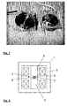
- shows a foto of an embodiment of the two pole pieces used in the present measuring tool; and
- Fig. 8
- an example for the arrangement of the components of a measuring tool according to the present invention.
- A high-temperature permeameter is a measuring tool for measuring the properties of magnetic materials in a closed-loop configuration. The measurement of the magnetisation J(H) = B - µo·H is critical for testing modern permanent magnet materials with high coercive fields, for example: samarium-cobalt alloys, neodymium-iron-boron alloys and samarium-iron nitrides. Fig. 8 shows an example for the arrangement of the components of a measuring tool according to the present invention. The measurement tool comprises an electromagnet 1 in a closed loop arrangement with two
pole pieces 3 connected to ayoke 2. Thepole pieces 3 form agap 4 for the placement of thesample 5. The measurement tool furthermore comprises two coils, one of which 6 measures the flux density B of thesample 5 and the other 7 records the field strength close to thesample 5. By connecting the twocoils - The high-temperature permeameter is connected to an electromagnet power supply, an electromagnet control unit, two integrating fluxmeters, and a controlling power supply for the heated pole pieces. These components which are not shown in the figures can be provided separately or can be part of the present measuring tool.
- Electronic fluxmeters are sensitive integrators with low drift and high input resistance. The accuracy of the fluxmeter is based on the drift, as the integration error can be kept relatively low by using a high degree of amplitude. With a drift of, for example, 10-5 Vs/minute, a flux of 104 Vs with a coil of 100 turns will by wrong by a maximum of 0.1% after one minute.
- In order to demagnetise a high-coercivity sample an electromagnet with a sufficiently large field is required. Modern magnetic materials can have coercivities in excess of 3 Tesla, however, a practical electromagnet with a 5-10-mm gap would normally be in the range 1.5-2.5 Tesla. The diameter of the
pole pieces 3 must be sufficient to allow for a completely uniform field in the region of the sample and the point where the field strength is determined. A practical minimum for measurements ofsamples 5 with diameters of 10-15 mm would be a pole diameter of 75 mm. Theheated pole pieces 3 must be well insulated from the main body of theelectromagnet yoke 2 in order to minimise heat losses and an unnecessarily large consumption of power. The insulating material must be designed to have the minimum effect on the magnetic field flowing from the main body of theyoke 2 into thepole pieces 3. The insulation gap should not exceed 7-8 mm. The pole-piece heaters must be supplied with sufficient power to raise the temperature of the pole-piece surface that is in contact with the magnet to 400ºC. - The J(H) curve of permanent magnets with any cross section can be measured with a J = B - µo·H compensated coil and a fluxmeter with an adjustable measuring constant. The J-compensated surrounding
coil 6 consists of 2 concentricfractional coils magnet sample 5 in the homogenous field produced by theelectromagnet pole pieces 3 thecoil 6 registers no flux. However, with asample 5 of cross-section A, a flux φ = N1·A·J is recorded. - In order to measure the magnetic properties of materials in the range of 400ºC. the J-compensated surrounding
coil 6 and thecoil 7 for measuring the magnetic field strength, together with any fixtures necessary to hold the coils in place must be able to withstand the effects of the temperature without the risk of any short-circuiting of the coil windings. - In a first embodiment the
coils cut alumina substrate 10 with dimensions 1.5 x 50 x 90 mm. Using a screen-printing technique thefirst coil layer 6a of thecoil 6 is applied to the surface of thesubstrate 10 as can be seen in Figure 1. - The coil layer is fabricated with a thick-film coating of silver-palladium (3:1) and consists of an inwardly-turning spiral with an outside diameter of 25 mm and an internal diameter of 13 mm. Figure 2 shows on the left-hand side the
plain substrate 10, on the right-hand side thesubstrate 10 with thefirst coil layer 6a. - The next stage involves firing the
coil layer 6a on thesubstrate 10. The initial firing is at 150ºC for 15 minutes; this is followed by a high-temperature firing at 850ºC for 30 minutes. On top of thecoil layer 6a we put an insulatinglayer 9. Thislayer 9 is almost complete except for a small via of approximately 0.3 mm to allow an electrically conducting connection to be made through the insulatinglayer 9. This insulatinglayer 9 is then fired at 150ºC for 15 minutes and 850ºC for 60 minutes. - A second
conducting coil layer 6b is applied over the insulatinglayer 9 to complete thecoil 6. Then a final insulatinglayer 16 is applied to provide electrical insulation and protection from damaging knocks and scratches. The reverse J-compensating coil and the magnetic field strength coil are applied in the same way. - Figure 3 shows on the left-hand side the first insulating
layer 9, in the centre thesecond coil layer 6b and on the right-hand side the top insulatinglayer 16. - In a second embodiment the reverse J- compensating
coil 6 and the field-measuringcoil 7 are elaborated in the same way as in Example 1, but with a different construction. Of the whole new coils have acircular H coil 7 and redesigned J coils 6a, 6b with fewer turns and larger spacing between the individual turns. The layout out the coils was also slightly altered to reduce the risks of short-circuiting. The design of the new J-coil 6 and a close up of the conducting tracks can be seen in Figure 4. The right-hand side of Figure 4 shows a close up of the J-coil 6 conducting tracks. - The stability of the coils was tested at tested for a range of temperatures from 450°C to 650°C. The results of these stability trials are as follows:
Resistance changes 450 °C / 100 hours <1.0% 550 °C / 100 hours <1.0% 650 °C / 100 hours <2.0% - In order to reduce the effects of thermally induced voltages and resistance changes at high temperature an electronic conditioning unit (ECU) 14 is developed that will be installed between the
coils fluxmeters 15. A schematic view of theECU 14 can be seen in the Figure 5. - The
heated pole pieces 3 consist of four main components: abase piece 11, for connecting to theyoke 2; an insulatinglayer 13, to reduce heat losses; thepole piece body 12, which forms the closed magnetic circuit with thetest sample 5; and the heater element 8 (Figure 6). - Both the
base piece 11 and thepole piece body 12 are round and machined from pure iron. The insulatingpiece 13 is 100 x 200 mm and 6-mm thick. The material is mica based, it has a density of about 2.2 kg/dm3 and a thermal conductivity of 0.26 W/mK. Theheaters 8 are made from NiCr 8020 wire with pure magnesium oxide. Eachheater 8 is 12.5 mm in diameter and 60-mm long (Figure 7). -
- 1
- electromagnet
- 2
- yoke
- 3
- pole piece
- 4
- gap
- 5
- magnetic sample
- 6
- search coil
- 6a
- flat coil element
- 6b
- flat coil element
- 7
- magnetic field strength measuring coil
- 8
- heater element
- 9
- insulating layer
- 10
- common substrate
- 11
- base piece
- 12
- pole piece body
- 13
- insulating layer
- 14
- ECU
- 15
- fluxmeter
- 16
- top insulating layer
Claims (10)
- Measuring tool for measuring magnetic properties of a magnetic sample in a closed loop, comprising- an electromagnet (1) in a closed loop arrangement with two pole pieces (3) connected to a yoke (2), said pole pieces (3) forming a gap (4) for the placement of the sample (5),- a search coil (6) for the measurement of a flux density B of the sample (5) and- a magnetic field sensor (7) for the measurment of a magnetic field strength H in the gap (4) between said pole pieces (3),characterized in that
the pole pieces (3) comprise heater elements (8) for heating the pole pieces (3) to temperatures of at least 450° C, the pole pieces (3) are thermally insulated against the yoke (2) of the electromagnet (1), and the pole pieces (3), the search coil (6) and the magnetic field sensor (7) are made of materials which resist said high temperatures. - A measuring tool according to claim 1,
characterized in that
the search coil (6) is made using thick-film technology. - A measuring tool according to claim 2 ,
characterized in that
the search coil (6) is made of two concentric flat coil elements (6a, 6b) of equal turn areas arranged one above the other and separated by an insulating layer (9) having a via through which the two flat coil elements (6a, 6b) are connected. - A measuring tool according to one of claims 1 to 3,
characterized in that
the magnetic field sensor is a flat coil (7). - A measuring tool according to claim 4,
characterized in that
the coil (7) of the magnetic field sensor is made using thick-film technology. - A measuring tool according to claim 5,
characterized in that
the coil (7) of the magnetic field sensor and the search coil (6) are arranged on a common substrate (10). - A measuring tool according to one of claims 1 to 6,
characterized in that
each of the pole pieces (3) consist of a base piece (11) for the connection to the yoke (2), a pole piece body (12) forming the closed magnetic circuit with the sample (5), an insulating layer (13) between the base piece (11) and the pole piece body (12) for a reduction of heat losses and at least one heater element (8) integrated in the pole piece body (12). - A measuring tool according to claim 7,
characterized in that
the base piece (11) and the pole piece body (12) have a circular cross section round and are machined from pure iron. - A measuring tool according to claim 7 or 8,
characterized in that
the insulating layer (13) is made of a material which is mica based and has a density of about 2.2 kg/dm3 and a thermal conductivity of about 0.26 W/mK. - A measuring tool according to claim 9,
characterized in that
the insulating layer (13) has lateral dimensions of 100 x 200 mm and is 6-mm thick.
Priority Applications (1)
| Application Number | Priority Date | Filing Date | Title |
|---|---|---|---|
| SI200331143T SI1671146T1 (en) | 2003-10-07 | 2003-10-07 | Permeameter for measuring magnetic properties at high temperatures |
Applications Claiming Priority (1)
| Application Number | Priority Date | Filing Date | Title |
|---|---|---|---|
| PCT/EP2003/011086 WO2005040842A1 (en) | 2003-10-07 | 2003-10-07 | Permeater for measuring magnetic properties at high temperatures |
Publications (2)
| Publication Number | Publication Date |
|---|---|
| EP1671146A1 EP1671146A1 (en) | 2006-06-21 |
| EP1671146B1 true EP1671146B1 (en) | 2007-12-05 |
Family
ID=34486004
Family Applications (1)
| Application Number | Title | Priority Date | Filing Date |
|---|---|---|---|
| EP03757921A Expired - Lifetime EP1671146B1 (en) | 2003-10-07 | 2003-10-07 | Permeameter for measuring magnetic properties at high temperatures |
Country Status (9)
| Country | Link |
|---|---|
| US (1) | US7368906B2 (en) |
| EP (1) | EP1671146B1 (en) |
| AT (1) | ATE380350T1 (en) |
| DE (1) | DE60317949T2 (en) |
| DK (1) | DK1671146T3 (en) |
| ES (1) | ES2298565T3 (en) |
| PT (1) | PT1671146E (en) |
| SI (1) | SI1671146T1 (en) |
| WO (1) | WO2005040842A1 (en) |
Cited By (1)
| Publication number | Priority date | Publication date | Assignee | Title |
|---|---|---|---|---|
| CN107153093A (en) * | 2016-03-04 | 2017-09-12 | 中国石油化工股份有限公司 | A kind of system and method for being used to measure the magnetic conductivity of simulation reservoir |
Families Citing this family (5)
| Publication number | Priority date | Publication date | Assignee | Title |
|---|---|---|---|---|
| JP7032369B2 (en) * | 2019-11-22 | 2022-03-08 | 電子磁気工業株式会社 | Magnetic property measuring device and magnetic property measuring method |
| CN112179780B (en) * | 2020-09-27 | 2022-08-16 | 江西荧光磁业有限公司 | Blank inspection device suitable for neodymium iron boron magnet and implementation method thereof |
| CN113093072B (en) | 2021-04-09 | 2022-11-15 | 中国计量大学 | A device and method for measuring the magnetism of permanent magnet materials at high temperature |
| CN117491474A (en) * | 2023-12-20 | 2024-02-02 | 东北大学 | A detection and calculation method for measuring austenite content in steel based on magnetic permeability meter |
| CN117907904A (en) * | 2024-01-26 | 2024-04-19 | 中国计量大学 | Quick measuring device and measuring method for failure temperature of permanent magnet |
Family Cites Families (6)
| Publication number | Priority date | Publication date | Assignee | Title |
|---|---|---|---|---|
| US2502628A (en) * | 1947-02-14 | 1950-04-04 | Indiana Steel Products Co | Permeameter |
| US3720870A (en) * | 1971-07-19 | 1973-03-13 | O Sueda | Apparatus for determining the permeability of a non-magnetic medium |
| SU890286A1 (en) | 1980-03-06 | 1981-12-15 | Рижский Краснознаменный Институт Инженеров Гражданской Авиации Им.Ленинского Комсомола | Temperature permeameter |
| SU922672A1 (en) | 1980-06-06 | 1982-04-23 | Рижский Краснознаменный Институт Инженеров Гражданской Авиации Им.Ленинского Комсомола | Temperature permeameter |
| GB2324609B (en) * | 1997-04-23 | 2001-06-27 | Redcliffe Magtronics Ltd | Means for determining the characteristic of a magnetic sample |
| US6843106B2 (en) * | 2000-03-08 | 2005-01-18 | Rensselaer Polytechnic Institute | Differential permeometer |
-
2003
- 2003-10-07 AT AT03757921T patent/ATE380350T1/en not_active IP Right Cessation
- 2003-10-07 US US10/574,936 patent/US7368906B2/en not_active Expired - Fee Related
- 2003-10-07 PT PT03757921T patent/PT1671146E/en unknown
- 2003-10-07 DE DE60317949T patent/DE60317949T2/en not_active Expired - Lifetime
- 2003-10-07 WO PCT/EP2003/011086 patent/WO2005040842A1/en not_active Ceased
- 2003-10-07 EP EP03757921A patent/EP1671146B1/en not_active Expired - Lifetime
- 2003-10-07 DK DK03757921T patent/DK1671146T3/en active
- 2003-10-07 SI SI200331143T patent/SI1671146T1/en unknown
- 2003-10-07 ES ES03757921T patent/ES2298565T3/en not_active Expired - Lifetime
Cited By (1)
| Publication number | Priority date | Publication date | Assignee | Title |
|---|---|---|---|---|
| CN107153093A (en) * | 2016-03-04 | 2017-09-12 | 中国石油化工股份有限公司 | A kind of system and method for being used to measure the magnetic conductivity of simulation reservoir |
Also Published As
| Publication number | Publication date |
|---|---|
| DE60317949T2 (en) | 2008-11-27 |
| US20070216404A1 (en) | 2007-09-20 |
| DE60317949D1 (en) | 2008-01-17 |
| EP1671146A1 (en) | 2006-06-21 |
| ES2298565T3 (en) | 2008-05-16 |
| SI1671146T1 (en) | 2008-08-31 |
| ATE380350T1 (en) | 2007-12-15 |
| DK1671146T3 (en) | 2008-04-14 |
| US7368906B2 (en) | 2008-05-06 |
| WO2005040842A1 (en) | 2005-05-06 |
| PT1671146E (en) | 2008-03-12 |
Similar Documents
| Publication | Publication Date | Title |
|---|---|---|
| CN1606100B (en) | Magnetic materials, passive shims and magnetic resonance imaging systems | |
| Schlamminger | Design of the permanent-magnet system for NIST-4 | |
| Patel et al. | Magnetic levitation between a slab of soldered HTS tape and a cylindrical permanent magnet | |
| JP2006203173A (en) | Magnetization method of permanent magnet | |
| de La Barrière et al. | 1-D and 2-D loss-measuring methods: Optimized setup design, advanced testing, and results | |
| Zherlitsyn et al. | Design and performance of non-destructive pulsed magnets at the Dresden High Magnetic Field Laboratory | |
| US7368906B2 (en) | Tool for measuring magnetic properties at high temperatures | |
| Demas et al. | Compact magnets for magnetic resonance | |
| Algarabel et al. | High field magnetostriction and magnetic thermal expansion of RE2Fe14B hard intermetallics | |
| Gould | Permanent magnets | |
| Abe et al. | Nuclear demagnetization for ultra-low temperatures | |
| Sanford et al. | Basic magnetic quantities and the measurement of the magnetic properties of materials | |
| Malla et al. | Effect of composition on the magnetic and elastic properties of shape-memory Ni-Mn-Ga | |
| Li et al. | Research of fast-response giant magnetostrictive actuator for space propulsion system | |
| Wu et al. | Study on Temperature-Insensitive Permanent Magnet Eddy Current Retarder Using Magnetic Shunt Compensation Method | |
| Kumar et al. | Thermally stable multi-directional magnetoelectric based embedded magnetic sensor | |
| Niedra | MH characteristics and demagnetization resistance of samarium-cobalt permanent magnets to 300 C | |
| Hwang et al. | Feasibility study of a multipole electromagnet using a parallel iron-core structure | |
| Niedra | The 23 to 300 C demagnetization resistance of samarium-cobalt permanent magnets | |
| Niedra et al. | Makeup and uses of a basic magnet laboratory for characterizing high-temperature permanent magnets | |
| Bashir et al. | Effect of temperature on magnetic characteristics of NdFeB alloy | |
| US10712405B2 (en) | External air core flux measurement system for a production magnetizing system | |
| Abdelnour et al. | Properties of various sintered rare earth-cobalt permanent magnets between-60° and+ 200° C | |
| Del Moral et al. | Forced volume magnetostriction in (rare earth) ni2 cubic intermetallic compounds | |
| Nakagawa et al. | Magnetic hysteresis and demagnetizing-field correction for rare earth magnet materials |
Legal Events
| Date | Code | Title | Description |
|---|---|---|---|
| PUAI | Public reference made under article 153(3) epc to a published international application that has entered the european phase |
Free format text: ORIGINAL CODE: 0009012 |
|
| 17P | Request for examination filed |
Effective date: 20060329 |
|
| AK | Designated contracting states |
Kind code of ref document: A1 Designated state(s): AT BE BG CH CY CZ DE DK EE ES FI FR GB GR HU IE IT LI LU MC NL PT RO SE SI SK TR |
|
| RIN1 | Information on inventor provided before grant (corrected) |
Inventor name: KOBE, SPOMENKA Inventor name: GERSAK, GREGOR Inventor name: MCGUINESS, PAUL, JOHN |
|
| GRAP | Despatch of communication of intention to grant a patent |
Free format text: ORIGINAL CODE: EPIDOSNIGR1 |
|
| GRAS | Grant fee paid |
Free format text: ORIGINAL CODE: EPIDOSNIGR3 |
|
| GRAA | (expected) grant |
Free format text: ORIGINAL CODE: 0009210 |
|
| AK | Designated contracting states |
Kind code of ref document: B1 Designated state(s): AT BE BG CH CY CZ DE DK EE ES FI FR GB GR HU IE IT LI LU MC NL PT RO SE SI SK TR |
|
| REG | Reference to a national code |
Ref country code: GB Ref legal event code: FG4D |
|
| REG | Reference to a national code |
Ref country code: IE Ref legal event code: FG4D |
|
| REG | Reference to a national code |
Ref country code: CH Ref legal event code: EP |
|
| REF | Corresponds to: |
Ref document number: 60317949 Country of ref document: DE Date of ref document: 20080117 Kind code of ref document: P |
|
| REG | Reference to a national code |
Ref country code: RO Ref legal event code: EPE |
|
| REG | Reference to a national code |
Ref country code: PT Ref legal event code: SC4A Free format text: AVAILABILITY OF NATIONAL TRANSLATION Effective date: 20080229 |
|
| REG | Reference to a national code |
Ref country code: SE Ref legal event code: TRGR |
|
| REG | Reference to a national code |
Ref country code: DK Ref legal event code: T3 |
|
| REG | Reference to a national code |
Ref country code: GR Ref legal event code: EP Ref document number: 20080400639 Country of ref document: GR |
|
| REG | Reference to a national code |
Ref country code: ES Ref legal event code: FG2A Ref document number: 2298565 Country of ref document: ES Kind code of ref document: T3 |
|
| REG | Reference to a national code |
Ref country code: CH Ref legal event code: NV Representative=s name: RENTSCH & PARTNER |
|
| PGFP | Annual fee paid to national office [announced via postgrant information from national office to epo] |
Ref country code: RO Payment date: 20080228 Year of fee payment: 6 |
|
| REG | Reference to a national code |
Ref country code: HU Ref legal event code: AG4A Ref document number: E003011 Country of ref document: HU |
|
| ET | Fr: translation filed | ||
| PGFP | Annual fee paid to national office [announced via postgrant information from national office to epo] |
Ref country code: TR Payment date: 20080304 Year of fee payment: 6 |
|
| PLBE | No opposition filed within time limit |
Free format text: ORIGINAL CODE: 0009261 |
|
| STAA | Information on the status of an ep patent application or granted ep patent |
Free format text: STATUS: NO OPPOSITION FILED WITHIN TIME LIMIT |
|
| 26N | No opposition filed |
Effective date: 20080908 |
|
| BERE | Be: lapsed |
Owner name: INSTITUTE JOZEF STEFAN Effective date: 20081031 |
|
| PG25 | Lapsed in a contracting state [announced via postgrant information from national office to epo] |
Ref country code: MC Free format text: LAPSE BECAUSE OF NON-PAYMENT OF DUE FEES Effective date: 20081031 |
|
| REG | Reference to a national code |
Ref country code: CH Ref legal event code: PL |
|
| REG | Reference to a national code |
Ref country code: DK Ref legal event code: EBP |
|
| REG | Reference to a national code |
Ref country code: EE Ref legal event code: MM4A Ref document number: E002042 Country of ref document: EE Effective date: 20081031 |
|
| EUG | Se: european patent has lapsed | ||
| REG | Reference to a national code |
Ref country code: PT Ref legal event code: MM4A Free format text: LAPSE DUE TO NON-PAYMENT OF FEES Effective date: 20090707 |
|
| PG25 | Lapsed in a contracting state [announced via postgrant information from national office to epo] |
Ref country code: SI Free format text: LAPSE BECAUSE OF NON-PAYMENT OF DUE FEES Effective date: 20081008 Ref country code: EE Free format text: LAPSE BECAUSE OF NON-PAYMENT OF DUE FEES Effective date: 20081031 Ref country code: FI Free format text: LAPSE BECAUSE OF NON-PAYMENT OF DUE FEES Effective date: 20081007 |
|
| PG25 | Lapsed in a contracting state [announced via postgrant information from national office to epo] |
Ref country code: IT Free format text: LAPSE BECAUSE OF NON-PAYMENT OF DUE FEES Effective date: 20081007 Ref country code: CZ Free format text: LAPSE BECAUSE OF NON-PAYMENT OF DUE FEES Effective date: 20081007 |
|
| REG | Reference to a national code |
Ref country code: SI Ref legal event code: KO00 Effective date: 20090601 |
|
| PG25 | Lapsed in a contracting state [announced via postgrant information from national office to epo] |
Ref country code: SK Free format text: LAPSE BECAUSE OF NON-PAYMENT OF DUE FEES Effective date: 20081007 Ref country code: BE Free format text: LAPSE BECAUSE OF NON-PAYMENT OF DUE FEES Effective date: 20081031 |
|
| PG25 | Lapsed in a contracting state [announced via postgrant information from national office to epo] |
Ref country code: CY Free format text: LAPSE BECAUSE OF NON-PAYMENT OF DUE FEES Effective date: 20081007 Ref country code: CH Free format text: LAPSE BECAUSE OF NON-PAYMENT OF DUE FEES Effective date: 20081031 Ref country code: PT Free format text: LAPSE BECAUSE OF NON-PAYMENT OF DUE FEES Effective date: 20090707 Ref country code: LI Free format text: LAPSE BECAUSE OF NON-PAYMENT OF DUE FEES Effective date: 20081031 Ref country code: DK Free format text: LAPSE BECAUSE OF NON-PAYMENT OF DUE FEES Effective date: 20081031 Ref country code: HU Free format text: LAPSE BECAUSE OF NON-PAYMENT OF DUE FEES Effective date: 20081008 |
|
| PG25 | Lapsed in a contracting state [announced via postgrant information from national office to epo] |
Ref country code: GR Free format text: LAPSE BECAUSE OF NON-PAYMENT OF DUE FEES Effective date: 20090505 |
|
| REG | Reference to a national code |
Ref country code: ES Ref legal event code: FD2A Effective date: 20081008 |
|
| PG25 | Lapsed in a contracting state [announced via postgrant information from national office to epo] |
Ref country code: ES Free format text: LAPSE BECAUSE OF NON-PAYMENT OF DUE FEES Effective date: 20081008 |
|
| PGFP | Annual fee paid to national office [announced via postgrant information from national office to epo] |
Ref country code: AT Payment date: 20091030 Year of fee payment: 7 Ref country code: DE Payment date: 20091021 Year of fee payment: 7 Ref country code: IE Payment date: 20091027 Year of fee payment: 7 |
|
| PGFP | Annual fee paid to national office [announced via postgrant information from national office to epo] |
Ref country code: NL Payment date: 20091030 Year of fee payment: 7 |
|
| PGFP | Annual fee paid to national office [announced via postgrant information from national office to epo] |
Ref country code: FR Payment date: 20091116 Year of fee payment: 7 Ref country code: GB Payment date: 20091030 Year of fee payment: 7 |
|
| PG25 | Lapsed in a contracting state [announced via postgrant information from national office to epo] |
Ref country code: SE Free format text: LAPSE BECAUSE OF NON-PAYMENT OF DUE FEES Effective date: 20081008 Ref country code: LU Free format text: LAPSE BECAUSE OF NON-PAYMENT OF DUE FEES Effective date: 20081007 |
|
| PG25 | Lapsed in a contracting state [announced via postgrant information from national office to epo] |
Ref country code: BG Free format text: LAPSE BECAUSE OF FAILURE TO SUBMIT A TRANSLATION OF THE DESCRIPTION OR TO PAY THE FEE WITHIN THE PRESCRIBED TIME-LIMIT Effective date: 20071205 |
|
| PG25 | Lapsed in a contracting state [announced via postgrant information from national office to epo] |
Ref country code: RO Free format text: LAPSE BECAUSE OF NON-PAYMENT OF DUE FEES Effective date: 20091007 |
|
| REG | Reference to a national code |
Ref country code: NL Ref legal event code: V1 Effective date: 20110501 |
|
| GBPC | Gb: european patent ceased through non-payment of renewal fee |
Effective date: 20101007 |
|
| PG25 | Lapsed in a contracting state [announced via postgrant information from national office to epo] |
Ref country code: FR Free format text: LAPSE BECAUSE OF NON-PAYMENT OF DUE FEES Effective date: 20101102 |
|
| REG | Reference to a national code |
Ref country code: FR Ref legal event code: ST Effective date: 20110630 |
|
| PG25 | Lapsed in a contracting state [announced via postgrant information from national office to epo] |
Ref country code: NL Free format text: LAPSE BECAUSE OF NON-PAYMENT OF DUE FEES Effective date: 20110501 Ref country code: GB Free format text: LAPSE BECAUSE OF NON-PAYMENT OF DUE FEES Effective date: 20101007 Ref country code: AT Free format text: LAPSE BECAUSE OF NON-PAYMENT OF DUE FEES Effective date: 20101007 |
|
| REG | Reference to a national code |
Ref country code: DE Ref legal event code: R119 Ref document number: 60317949 Country of ref document: DE Effective date: 20110502 |
|
| PG25 | Lapsed in a contracting state [announced via postgrant information from national office to epo] |
Ref country code: IE Free format text: LAPSE BECAUSE OF NON-PAYMENT OF DUE FEES Effective date: 20101007 |
|
| PG25 | Lapsed in a contracting state [announced via postgrant information from national office to epo] |
Ref country code: TR Free format text: LAPSE BECAUSE OF NON-PAYMENT OF DUE FEES Effective date: 20091007 |
|
| PG25 | Lapsed in a contracting state [announced via postgrant information from national office to epo] |
Ref country code: DE Free format text: LAPSE BECAUSE OF NON-PAYMENT OF DUE FEES Effective date: 20110502 |