EP1671036B1 - Inlet hopper construction for a twin-screw pump - Google Patents
Inlet hopper construction for a twin-screw pump Download PDFInfo
- Publication number
- EP1671036B1 EP1671036B1 EP03818493A EP03818493A EP1671036B1 EP 1671036 B1 EP1671036 B1 EP 1671036B1 EP 03818493 A EP03818493 A EP 03818493A EP 03818493 A EP03818493 A EP 03818493A EP 1671036 B1 EP1671036 B1 EP 1671036B1
- Authority
- EP
- European Patent Office
- Prior art keywords
- feed screws
- inlet hopper
- screws
- accordance
- pump
- Prior art date
- Legal status (The legal status is an assumption and is not a legal conclusion. Google has not performed a legal analysis and makes no representation as to the accuracy of the status listed.)
- Expired - Lifetime
Links
- 238000010276 construction Methods 0.000 title claims abstract description 32
- 230000010006 flight Effects 0.000 claims abstract description 4
- 230000015572 biosynthetic process Effects 0.000 claims description 11
- 230000007704 transition Effects 0.000 claims description 7
- 230000033001 locomotion Effects 0.000 claims description 3
- 238000005755 formation reaction Methods 0.000 description 9
- 238000005086 pumping Methods 0.000 description 2
- 238000012986 modification Methods 0.000 description 1
- 230000004048 modification Effects 0.000 description 1
- 235000013580 sausages Nutrition 0.000 description 1
Images

Classifications
-
- F—MECHANICAL ENGINEERING; LIGHTING; HEATING; WEAPONS; BLASTING
- F01—MACHINES OR ENGINES IN GENERAL; ENGINE PLANTS IN GENERAL; STEAM ENGINES
- F01C—ROTARY-PISTON OR OSCILLATING-PISTON MACHINES OR ENGINES
- F01C11/00—Combinations of two or more machines or engines, each being of rotary-piston or oscillating-piston type
- F01C11/006—Combinations of two or more machines or engines, each being of rotary-piston or oscillating-piston type of dissimilar working principle
-
- F—MECHANICAL ENGINEERING; LIGHTING; HEATING; WEAPONS; BLASTING
- F01—MACHINES OR ENGINES IN GENERAL; ENGINE PLANTS IN GENERAL; STEAM ENGINES
- F01C—ROTARY-PISTON OR OSCILLATING-PISTON MACHINES OR ENGINES
- F01C21/00—Component parts, details or accessories not provided for in groups F01C1/00 - F01C20/00
- F01C21/10—Outer members for co-operation with rotary pistons; Casings
-
- F—MECHANICAL ENGINEERING; LIGHTING; HEATING; WEAPONS; BLASTING
- F04—POSITIVE - DISPLACEMENT MACHINES FOR LIQUIDS; PUMPS FOR LIQUIDS OR ELASTIC FLUIDS
- F04C—ROTARY-PISTON, OR OSCILLATING-PISTON, POSITIVE-DISPLACEMENT MACHINES FOR LIQUIDS; ROTARY-PISTON, OR OSCILLATING-PISTON, POSITIVE-DISPLACEMENT PUMPS
- F04C2/00—Rotary-piston machines or pumps
- F04C2/08—Rotary-piston machines or pumps of intermeshing-engagement type, i.e. with engagement of co-operating members similar to that of toothed gearing
- F04C2/12—Rotary-piston machines or pumps of intermeshing-engagement type, i.e. with engagement of co-operating members similar to that of toothed gearing of other than internal-axis type
- F04C2/14—Rotary-piston machines or pumps of intermeshing-engagement type, i.e. with engagement of co-operating members similar to that of toothed gearing of other than internal-axis type with toothed rotary pistons
- F04C2/16—Rotary-piston machines or pumps of intermeshing-engagement type, i.e. with engagement of co-operating members similar to that of toothed gearing of other than internal-axis type with toothed rotary pistons with helical teeth, e.g. chevron-shaped, screw type
Definitions
- the present invention relates to an inlet hopper construction for a twin-screw pump of the kind set forth in the preamble of claim 1.
- inlet hopper constructions for twin-screw pumps of this kind it is known to provide the feed screws in the bottom part of the hopper with a close fitting between the screws and the bottom of the inlet hopper by having a cylindrical bottom formation with approximately same radius of curvature as the radius of the feed screws and having this cylindrical formation extending to approximately half way up along the sides of the feed screws, where a mainly planar extension is forming the rest of the hopper construction.
- a hopper construction of this kind is e.g. known from US-4,566,640 and US-4,685,628 .
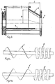
- the inlet hopper construction shown in Figures 1-3 for a twin-screw pump comprises two mutually engaging feed screws 1,1' positioned at the bottom of the inlet hopper 3 for feeding the material from the hopper 3 toward the twin-screw pump.
- the twin-screw pump comprises two mutually engaging pump screws 2,2', preferably with constant pitch, as shown in Figures 4a and 4b, which in the embodiment shown are positioned on a shaft common with the shaft of the feed screws 1,1', and thus aligned co-axially with the feed screws.
- the twin-screw pump comprises a pump casing 4 (not shown in detail) and the pump screws 2,2' are positioned in the casing 4 with close clearances between the casing 4 and between the mutually engaging flights and grooves of the pump screws 2,2'.
- the function of the twin-screw pump is as known from the prior art and it should not be necessary here to explain this function in detail.
- the twin-screw pump has its pumping screws 2,2' extending out of the casing 4 in order to prevent the twin-screw pump from being "over-filled".
- the twin-screw pump is used for dosing material, e.g. for filling sausages
- the filling of the pumping screws 2,2' will normally only reach 80%-85%, especially in connection with certain high viscosity or lumpy material. The result of such insufficient filling is a reduced precision of the dosing of material out of the twin-screw pump.
- the present invention prescribes the provision of a widening out 5 along the outer sides of the feed screws 1,1', which allows the material in the hopper 3 to enter into the grooves of the feed screws 1,1' from the sides as well as from the top.
- the widening out 5 along the outer sides of the feed screws 1,1' are formed as a cylindrical formation of the bottom with a radius R+X, which is larger than the outer radius R of the feed screws 1,1', and the inlet hopper 3 is formed with a close fitting with the bottom part of the feed screws 1,1' by having the centre for the cylindrical formation of the bottom part positioned at a distance Y above the centre for the feed screws 1,1', where Y ⁇ X.
- the position of the centre for the cylindrical formation of the bottom part can be positioned at a distance Y in a direction deviating from vertical by an angle ⁇ and with the same restrictions between X and Y as mentioned above.
- the angle ⁇ is preferably between 0° (as shown in Figure 2) and 30°.
- the value of X is between 10 and 50% of R and the value of Y is X - ⁇ , where ⁇ is between 0 and 5% of R.
- the hopper construction 3 is provided with a conically narrowing transition part 6 between the widening out bottom part 5 and the pump casing 4.
- This conical narrowing transition part 6 provides a further increased filling of the feed screws 1,1', when the material in the hopper 3 is transported towards the pump screws 2,2' and the pump casing 4.
- the conical narrowing transition part 6 is formed as a combination of two truncated cones, thus providing a smooth transition from the two cylindrical hopper bottom parts with radius R+X to the two cylindrical pump casings 4 with radius R.
- the cone angle i.e. the top angle of the cone is approximately 30°. Other angles are naturally possible, but this angle should preferably be kept below 50°.
- the bottom part of the hopper construction 3 is provided with axially extending rails 7 in order to guide the material axially along the feed screws 1,1' during the rotational movement of said feed screws 1,1'.
- the screws 1,2 and 1',2', respectively are rotating in opposite directions and in such directions that the movement direction of the feed screws 1,1' along the outer sides of the hopper 3 is in the direction of the bottom of the inlet hopper 3.
- Such a rotational direction will improve the function of the widening out 5 along the outer sides of the feed screws 1,1' for improved filling of the feed screws 1,1' and accordingly, the pump screws 2,2'.
- the radius R for the feed screws 1,1' and the pump screws 2,2' is constant and identical, but for a man skilled in the art it will be evident that other formations of the feed screws and the pump screws can be envisaged.
- the feed screws 1,1' are formed with relatively narrow flights and relatively broad grooves, which is especially suitable in connection with high viscosity and/or lumpy material.
- the feed screws 1,1' can be formed in other ways, e.g. identical to the pump screws 2,2', said last possibility being an advantage in connection with materials of low viscosity.
- the filling of the pump screws 2,2' can be increased from 85%, as measured on a traditional construction, to approximately 98-99%, as measured with the preferred embodiment.
Landscapes
- Engineering & Computer Science (AREA)
- Mechanical Engineering (AREA)
- General Engineering & Computer Science (AREA)
- Rotary Pumps (AREA)
- Reciprocating Pumps (AREA)
- Details And Applications Of Rotary Liquid Pumps (AREA)
- On-Site Construction Work That Accompanies The Preparation And Application Of Concrete (AREA)
Abstract
Description
- The present invention relates to an inlet hopper construction for a twin-screw pump of the kind set forth in the preamble of claim 1.
- In inlet hopper constructions for twin-screw pumps of this kind it is known to provide the feed screws in the bottom part of the hopper with a close fitting between the screws and the bottom of the inlet hopper by having a cylindrical bottom formation with approximately same radius of curvature as the radius of the feed screws and having this cylindrical formation extending to approximately half way up along the sides of the feed screws, where a mainly planar extension is forming the rest of the hopper construction. A hopper construction of this kind is e.g. known from
US-4,566,640 andUS-4,685,628 . - It is the object of the present invention to provide an inlet hopper construction of the kind referred to above, with which it is possible to improve the filling of the feed screws and consequently the filling of the pump screws, and this object is achieved with an inlet hopper construction for a twin-screw pump of said kind, which according to the present invention also comprises the features set forth in the characterising clause of claim 1. With this arrangement, the material from the hopper is able to fill the feed screw grooves from the sides as well as from the top of said feed screws, whereby the filling of the feed screws and consequently the pump screws is increased compared to the constructions in accordance with the prior art.
- In the following detailed part of the present description, the invention will be explained in more detail with reference to the exemplary embodiment of an inlet hopper construction for a twin-screw pump according to the invention shown in the drawings, in which
- Figure 1 schematically shows a cross section of an inlet hopper construction in accordance with a preferred embodiment of the present invention with feed screws mounted therein,
- Figure 2 schematically shows the construction in Figure 1 for indicating the different radii of the feed screws and the cylindrical formation of the bottom of the hopper construction,
- Figure 3 shows the construction of Figures 1 and 2 in a longitudinal cross section, and
- Figures 4a and 4b schematically shows combined feed screws and pump screws for use in the hopper construction in accordance with the preferred embodiment.
- The inlet hopper construction shown in Figures 1-3 for a twin-screw pump comprises two mutually engaging feed screws 1,1' positioned at the bottom of the
inlet hopper 3 for feeding the material from thehopper 3 toward the twin-screw pump. The twin-screw pump comprises two mutually engaging pump screws 2,2', preferably with constant pitch, as shown in Figures 4a and 4b, which in the embodiment shown are positioned on a shaft common with the shaft of the feed screws 1,1', and thus aligned co-axially with the feed screws. Furthermore, the twin-screw pump comprises a pump casing 4 (not shown in detail) and the pump screws 2,2' are positioned in thecasing 4 with close clearances between thecasing 4 and between the mutually engaging flights and grooves of the pump screws 2,2'. The function of the twin-screw pump is as known from the prior art and it should not be necessary here to explain this function in detail. In the embodiment shown in the drawings, the twin-screw pump has its pumping screws 2,2' extending out of thecasing 4 in order to prevent the twin-screw pump from being "over-filled". - In certain applications, in which the twin-screw pump is used for dosing material, e.g. for filling sausages, it is of major importance that the pump screws 2,2' are completely filled with material from the
hopper 3. In traditional constructions, e.g. as known from the above-mentionedUS-4,566,640 , the filling of the pumping screws 2,2' will normally only reach 80%-85%, especially in connection with certain high viscosity or lumpy material. The result of such insufficient filling is a reduced precision of the dosing of material out of the twin-screw pump. In order to increase the above filling percentage, the present invention prescribes the provision of a widening out 5 along the outer sides of the feed screws 1,1', which allows the material in thehopper 3 to enter into the grooves of the feed screws 1,1' from the sides as well as from the top. In the embodiment shown in the figures, the widening out 5 along the outer sides of the feed screws 1,1' are formed as a cylindrical formation of the bottom with a radius R+X, which is larger than the outer radius R of the feed screws 1,1', and theinlet hopper 3 is formed with a close fitting with the bottom part of the feed screws 1,1' by having the centre for the cylindrical formation of the bottom part positioned at a distance Y above the centre for the feed screws 1,1', where Y ≤ X. - As an alternative, the position of the centre for the cylindrical formation of the bottom part can be positioned at a distance Y in a direction deviating from vertical by an angle α and with the same restrictions between X and Y as mentioned above. The angle α is preferably between 0° (as shown in Figure 2) and 30°. In a preferred embodiment, the value of X is between 10 and 50% of R and the value of Y is X - δ, where δ is between 0 and 5% of R.
- It will be evident for a man skilled in the art that other formations than the cylindrical formation of the bottom part can provide a similar widening out 5 along the outer sides of the feed screws 1,1' and that the dimensioning of the widening out naturally will depend on the material to be fed towards the twin-screw pump, i.e. the viscosity, granularity, and other parameters for the pumped material.
- As shown in Figure 3, the
hopper construction 3 is provided with a conically narrowingtransition part 6 between the widening outbottom part 5 and thepump casing 4. This conicalnarrowing transition part 6 provides a further increased filling of the feed screws 1,1', when the material in thehopper 3 is transported towards the pump screws 2,2' and thepump casing 4. Preferably, the conicalnarrowing transition part 6 is formed as a combination of two truncated cones, thus providing a smooth transition from the two cylindrical hopper bottom parts with radius R+X to the twocylindrical pump casings 4 with radius R. In the embodiment shown, the cone angle, i.e. the top angle of the cone is approximately 30°. Other angles are naturally possible, but this angle should preferably be kept below 50°. - As shown in Figures 1-3, the bottom part of the
hopper construction 3 is provided with axially extendingrails 7 in order to guide the material axially along the feed screws 1,1' during the rotational movement of said feed screws 1,1'. - Preferably, the screws 1,2 and 1',2', respectively, are rotating in opposite directions and in such directions that the movement direction of the feed screws 1,1' along the outer sides of the
hopper 3 is in the direction of the bottom of theinlet hopper 3. Such a rotational direction will improve the function of the widening out 5 along the outer sides of the feed screws 1,1' for improved filling of the feed screws 1,1' and accordingly, the pump screws 2,2'. - In the embodiment shown, the radius R for the feed screws 1,1' and the pump screws 2,2' is constant and identical, but for a man skilled in the art it will be evident that other formations of the feed screws and the pump screws can be envisaged.
- In the embodiment shown in the drawings, the feed screws 1,1' are formed with relatively narrow flights and relatively broad grooves, which is especially suitable in connection with high viscosity and/or lumpy material. However, the feed screws 1,1' can be formed in other ways, e.g. identical to the pump screws 2,2', said last possibility being an advantage in connection with materials of low viscosity.
- Experiments have shown that with a construction corresponding to the above described preferred embodiment, the filling of the pump screws 2,2' can be increased from 85%, as measured on a traditional construction, to approximately 98-99%, as measured with the preferred embodiment.
- Above, the invention has been described in connection with a preferred embodiment and it will be evident for a man skilled in the art that many modifications can be made without departing from the scope of the appended claims.
Claims (10)
- Inlet hopper construction for a twin-screw pump comprising two mutually engaging feed screws (1,1'), said feed screws (1,1') being positioned at the bottom of the inlet hopper (3) for feeding the material towards the twin-screw pump,
two mutually engaging pump screws (2,2') aligned co-axially with the feed screws (1,1') and positioned in a pump casing with close clearances with said casing (4) and between the mutually engaging flights and grooves, said inlet hopper (3) being formed with a close fitting with the bottom part of the feed screws (1,1') and a widening out (5) along the outer sides of the feed screws (1,1') in order to allow the material in the hopper (3) to enter into the grooves of the feed screws (1,1') from the sides as well as from the top, characterised by the widening out (5) along the outer sides of the feed screws (1,1') being formed as a cylindrical formation of the bottom with a radius (R + X) which is larger than the outer radius (R) of the feed screws (1,1'). - Inlet hopper construction in accordance with claim 1, characterised by the distance Y (Y ≤ X) between the centre of the feed screws (1,1') and the centre for the cylindrical formation of the bottom part, whereby there is provided a close fitting between the bottom part of the feed screws (1,1') and the inlet hopper (3) bottom section.
- Inlet hopper construction in accordance with claim 2, characterised by comprising an angle α between the vertical direction and the line between the centres for the feed screws (1,1') and the centres for the cylindrical parts of the bottom of the hopper (3), where 0° ≤ α ≤ 30°.
- Inlet hopper construction in accordance with any of the preceding claims, characterised by choosing X = 10-50% of R and choosing Y = X - 6, where 0 < δ ≤ 5% of R.
- Inlet hopper construction in accordance with any of the preceding claims, characterised by further comprising a conically narrowing transition part (6) between the widening out bottom part and the pump casing.
- Inlet hopper construction in accordance with claim 5, characterised by the conical narrowing transition part (6) being formed as a combination of two truncated cones.
- Inlet hopper construction in accordance with claim 6, characterised by the cone angle γ of the conically narrowing transition part (6) being 10-50°, preferably 25-35°, and more preferred equal to 30°.
- Inlet hopper construction in accordance with any of the preceding claims, characterised by the rotational direction of the two mutually engaging feed screws (1,1') being such that the movement direction of said feed screws (1,1') along the outer sides is in the direction of the bottom of the inlet hopper (3).
- Inlet hopper construction in accordance with any of the preceding claims, characterised by the feed screws (1,1') and the pump screws (2,2') having the same diameter (2R).
- Inlet hopper construction in accordance with any of the preceding claims, characterised by comprising axially extending rails (7) in the bottom of the hopper construction for guiding the material axially along the feed screws (1, 1').
Applications Claiming Priority (1)
| Application Number | Priority Date | Filing Date | Title |
|---|---|---|---|
| PCT/DK2003/000583 WO2005024238A1 (en) | 2003-09-10 | 2003-09-10 | Inlet hopper construction for a twin-screw pump |
Publications (2)
| Publication Number | Publication Date |
|---|---|
| EP1671036A1 EP1671036A1 (en) | 2006-06-21 |
| EP1671036B1 true EP1671036B1 (en) | 2007-07-25 |
Family
ID=34259065
Family Applications (1)
| Application Number | Title | Priority Date | Filing Date |
|---|---|---|---|
| EP03818493A Expired - Lifetime EP1671036B1 (en) | 2003-09-10 | 2003-09-10 | Inlet hopper construction for a twin-screw pump |
Country Status (10)
| Country | Link |
|---|---|
| EP (1) | EP1671036B1 (en) |
| CN (1) | CN1839264A (en) |
| AT (1) | ATE368183T1 (en) |
| AU (1) | AU2003258494A1 (en) |
| BR (1) | BR0318499A (en) |
| DE (1) | DE60315201T2 (en) |
| DK (1) | DK1671036T3 (en) |
| ES (1) | ES2290559T3 (en) |
| NO (1) | NO20061192L (en) |
| WO (1) | WO2005024238A1 (en) |
Family Cites Families (2)
| Publication number | Priority date | Publication date | Assignee | Title |
|---|---|---|---|---|
| US4566640A (en) * | 1984-01-18 | 1986-01-28 | Beehive Machinery, Inc. | Separating machine having overlapping screw pump |
| US4685628A (en) * | 1985-09-06 | 1987-08-11 | Beehive Machinery, Inc. | Feed mechanism for a deboning machine or the like |
-
2003
- 2003-09-10 ES ES03818493T patent/ES2290559T3/en not_active Expired - Lifetime
- 2003-09-10 EP EP03818493A patent/EP1671036B1/en not_active Expired - Lifetime
- 2003-09-10 BR BRPI0318499-4A patent/BR0318499A/en unknown
- 2003-09-10 DE DE60315201T patent/DE60315201T2/en not_active Expired - Fee Related
- 2003-09-10 CN CNA038270528A patent/CN1839264A/en active Pending
- 2003-09-10 AU AU2003258494A patent/AU2003258494A1/en not_active Abandoned
- 2003-09-10 WO PCT/DK2003/000583 patent/WO2005024238A1/en not_active Ceased
- 2003-09-10 DK DK03818493T patent/DK1671036T3/en active
- 2003-09-10 AT AT03818493T patent/ATE368183T1/en not_active IP Right Cessation
-
2006
- 2006-03-14 NO NO20061192A patent/NO20061192L/en not_active Application Discontinuation
Also Published As
| Publication number | Publication date |
|---|---|
| BR0318499A (en) | 2006-09-12 |
| DE60315201D1 (en) | 2007-09-06 |
| ATE368183T1 (en) | 2007-08-15 |
| WO2005024238A1 (en) | 2005-03-17 |
| CN1839264A (en) | 2006-09-27 |
| NO20061192L (en) | 2006-03-14 |
| EP1671036A1 (en) | 2006-06-21 |
| AU2003258494A1 (en) | 2005-03-29 |
| DK1671036T3 (en) | 2007-11-26 |
| ES2290559T3 (en) | 2008-02-16 |
| DE60315201T2 (en) | 2008-05-08 |
Similar Documents
| Publication | Publication Date | Title |
|---|---|---|
| US9109595B2 (en) | Helical gear pump | |
| US9090013B2 (en) | Dual screw extrusion apparatus having a mixing chamber and a conveying chamber downstream thereof with the mixing chamber having a wall clearance greater than that of the conveying chamber | |
| TWI794305B (en) | Asymmetric three-bladed worm shaft for a mixing and kneading machine, section for such a worm shaft, housing containing the worm shaft, and corresponding mixing and kneading machine | |
| US6962431B1 (en) | Extruder mixer | |
| CN106133341A (en) | There is the clamp device of the material extrusion dish of axial restraint | |
| US20150298356A1 (en) | Mixing section for a plastic extrusion screw | |
| CA1161233A (en) | Low-energy extruder-pump system | |
| US10807291B2 (en) | Extruder | |
| EP1207992B1 (en) | Extruder screw | |
| EP1671036A1 (en) | Inlet hopper construction for a twin-screw pump | |
| US6176606B1 (en) | Extruder screw | |
| CN105417205B (en) | Doffer | |
| US6106142A (en) | Pressure variable, multiscrew, continuous mixing machine for plasticizable compounds with variable height backfeed threads | |
| EP3461614A1 (en) | Extruder | |
| GB2122564A (en) | Apparatus and method for pneumatically conveying different types of material | |
| CN218944790U (en) | Three-dimensional stirring vane and silt mixer | |
| RU2315202C1 (en) | Intake charging gopper for two-screw pump | |
| CN203031916U (en) | Twin-screw thread element | |
| CN103950173A (en) | Tapered metering compression feeder | |
| KR101113053B1 (en) | Screw For Extruder | |
| CN207932496U (en) | A kind of Feed Manufacturing rotation delivery device | |
| CN216099691U (en) | Cement weighing equipment and concrete mixing equipment with same | |
| JP2012192560A (en) | Biaxial extruder | |
| EP3797967A1 (en) | Screw-type extruder | |
| CN200995992Y (en) | Continuous sensibilizer of emulsified explosive substrate |
Legal Events
| Date | Code | Title | Description |
|---|---|---|---|
| PUAI | Public reference made under article 153(3) epc to a published international application that has entered the european phase |
Free format text: ORIGINAL CODE: 0009012 |
|
| 17P | Request for examination filed |
Effective date: 20060410 |
|
| AK | Designated contracting states |
Kind code of ref document: A1 Designated state(s): AT BE BG CH CY CZ DE DK EE ES FI FR GB GR HU IE IT LI LU MC NL PT RO SE SI SK TR |
|
| AX | Request for extension of the european patent |
Extension state: LT LV |
|
| RAX | Requested extension states of the european patent have changed |
Extension state: LT Payment date: 20060410 Extension state: LV Payment date: 20060410 |
|
| GRAP | Despatch of communication of intention to grant a patent |
Free format text: ORIGINAL CODE: EPIDOSNIGR1 |
|
| GRAS | Grant fee paid |
Free format text: ORIGINAL CODE: EPIDOSNIGR3 |
|
| GRAA | (expected) grant |
Free format text: ORIGINAL CODE: 0009210 |
|
| AK | Designated contracting states |
Kind code of ref document: B1 Designated state(s): AT BE BG CH CY CZ DE DK EE ES FI FR GB GR HU IE IT LI LU MC NL PT RO SE SI SK TR |
|
| AX | Request for extension of the european patent |
Extension state: LT LV |
|
| REG | Reference to a national code |
Ref country code: GB Ref legal event code: FG4D |
|
| RIN1 | Information on inventor provided before grant (corrected) |
Inventor name: SIMONSEN, KNUD |
|
| REG | Reference to a national code |
Ref country code: CH Ref legal event code: EP |
|
| REG | Reference to a national code |
Ref country code: IE Ref legal event code: FG4D |
|
| REF | Corresponds to: |
Ref document number: 60315201 Country of ref document: DE Date of ref document: 20070906 Kind code of ref document: P |
|
| PGFP | Annual fee paid to national office [announced via postgrant information from national office to epo] |
Ref country code: DK Payment date: 20070925 Year of fee payment: 5 Ref country code: ES Payment date: 20070925 Year of fee payment: 5 |
|
| REG | Reference to a national code |
Ref country code: DK Ref legal event code: T3 |
|
| LTIE | Lt: invalidation of european patent or patent extension |
Effective date: 20070725 |
|
| ET | Fr: translation filed | ||
| PG25 | Lapsed in a contracting state [announced via postgrant information from national office to epo] |
Ref country code: PT Free format text: LAPSE BECAUSE OF FAILURE TO SUBMIT A TRANSLATION OF THE DESCRIPTION OR TO PAY THE FEE WITHIN THE PRESCRIBED TIME-LIMIT Effective date: 20071226 Ref country code: FI Free format text: LAPSE BECAUSE OF FAILURE TO SUBMIT A TRANSLATION OF THE DESCRIPTION OR TO PAY THE FEE WITHIN THE PRESCRIBED TIME-LIMIT Effective date: 20070725 Ref country code: BG Free format text: LAPSE BECAUSE OF FAILURE TO SUBMIT A TRANSLATION OF THE DESCRIPTION OR TO PAY THE FEE WITHIN THE PRESCRIBED TIME-LIMIT Effective date: 20071025 |
|
| PGFP | Annual fee paid to national office [announced via postgrant information from national office to epo] |
Ref country code: DE Payment date: 20071127 Year of fee payment: 5 Ref country code: IT Payment date: 20070926 Year of fee payment: 5 Ref country code: NL Payment date: 20070917 Year of fee payment: 5 |
|
| REG | Reference to a national code |
Ref country code: CH Ref legal event code: PL |
|
| REG | Reference to a national code |
Ref country code: ES Ref legal event code: FG2A Ref document number: 2290559 Country of ref document: ES Kind code of ref document: T3 |
|
| PG25 | Lapsed in a contracting state [announced via postgrant information from national office to epo] |
Ref country code: CH Free format text: LAPSE BECAUSE OF FAILURE TO SUBMIT A TRANSLATION OF THE DESCRIPTION OR TO PAY THE FEE WITHIN THE PRESCRIBED TIME-LIMIT Effective date: 20070725 Ref country code: AT Free format text: LAPSE BECAUSE OF FAILURE TO SUBMIT A TRANSLATION OF THE DESCRIPTION OR TO PAY THE FEE WITHIN THE PRESCRIBED TIME-LIMIT Effective date: 20070725 Ref country code: LI Free format text: LAPSE BECAUSE OF FAILURE TO SUBMIT A TRANSLATION OF THE DESCRIPTION OR TO PAY THE FEE WITHIN THE PRESCRIBED TIME-LIMIT Effective date: 20070725 |
|
| PG25 | Lapsed in a contracting state [announced via postgrant information from national office to epo] |
Ref country code: BE Free format text: LAPSE BECAUSE OF FAILURE TO SUBMIT A TRANSLATION OF THE DESCRIPTION OR TO PAY THE FEE WITHIN THE PRESCRIBED TIME-LIMIT Effective date: 20070725 |
|
| PG25 | Lapsed in a contracting state [announced via postgrant information from national office to epo] |
Ref country code: GR Free format text: LAPSE BECAUSE OF FAILURE TO SUBMIT A TRANSLATION OF THE DESCRIPTION OR TO PAY THE FEE WITHIN THE PRESCRIBED TIME-LIMIT Effective date: 20071026 Ref country code: MC Free format text: LAPSE BECAUSE OF NON-PAYMENT OF DUE FEES Effective date: 20070930 |
|
| PGFP | Annual fee paid to national office [announced via postgrant information from national office to epo] |
Ref country code: FR Payment date: 20070926 Year of fee payment: 5 |
|
| PG25 | Lapsed in a contracting state [announced via postgrant information from national office to epo] |
Ref country code: CZ Free format text: LAPSE BECAUSE OF FAILURE TO SUBMIT A TRANSLATION OF THE DESCRIPTION OR TO PAY THE FEE WITHIN THE PRESCRIBED TIME-LIMIT Effective date: 20070725 Ref country code: SK Free format text: LAPSE BECAUSE OF FAILURE TO SUBMIT A TRANSLATION OF THE DESCRIPTION OR TO PAY THE FEE WITHIN THE PRESCRIBED TIME-LIMIT Effective date: 20070725 |
|
| PLBE | No opposition filed within time limit |
Free format text: ORIGINAL CODE: 0009261 |
|
| STAA | Information on the status of an ep patent application or granted ep patent |
Free format text: STATUS: NO OPPOSITION FILED WITHIN TIME LIMIT |
|
| GBPC | Gb: european patent ceased through non-payment of renewal fee |
Effective date: 20071025 |
|
| PG25 | Lapsed in a contracting state [announced via postgrant information from national office to epo] |
Ref country code: RO Free format text: LAPSE BECAUSE OF FAILURE TO SUBMIT A TRANSLATION OF THE DESCRIPTION OR TO PAY THE FEE WITHIN THE PRESCRIBED TIME-LIMIT Effective date: 20070725 Ref country code: SE Free format text: LAPSE BECAUSE OF FAILURE TO SUBMIT A TRANSLATION OF THE DESCRIPTION OR TO PAY THE FEE WITHIN THE PRESCRIBED TIME-LIMIT Effective date: 20071025 |
|
| 26N | No opposition filed |
Effective date: 20080428 |
|
| PG25 | Lapsed in a contracting state [announced via postgrant information from national office to epo] |
Ref country code: IE Free format text: LAPSE BECAUSE OF NON-PAYMENT OF DUE FEES Effective date: 20070910 |
|
| PG25 | Lapsed in a contracting state [announced via postgrant information from national office to epo] |
Ref country code: GB Free format text: LAPSE BECAUSE OF NON-PAYMENT OF DUE FEES Effective date: 20071025 |
|
| PG25 | Lapsed in a contracting state [announced via postgrant information from national office to epo] |
Ref country code: EE Free format text: LAPSE BECAUSE OF FAILURE TO SUBMIT A TRANSLATION OF THE DESCRIPTION OR TO PAY THE FEE WITHIN THE PRESCRIBED TIME-LIMIT Effective date: 20070725 |
|
| REG | Reference to a national code |
Ref country code: DK Ref legal event code: EBP |
|
| PG25 | Lapsed in a contracting state [announced via postgrant information from national office to epo] |
Ref country code: NL Free format text: LAPSE BECAUSE OF NON-PAYMENT OF DUE FEES Effective date: 20090401 |
|
| NLV4 | Nl: lapsed or anulled due to non-payment of the annual fee |
Effective date: 20090401 |
|
| PG25 | Lapsed in a contracting state [announced via postgrant information from national office to epo] |
Ref country code: SI Free format text: LAPSE BECAUSE OF FAILURE TO SUBMIT A TRANSLATION OF THE DESCRIPTION OR TO PAY THE FEE WITHIN THE PRESCRIBED TIME-LIMIT Effective date: 20070725 |
|
| REG | Reference to a national code |
Ref country code: FR Ref legal event code: ST Effective date: 20090529 |
|
| PG25 | Lapsed in a contracting state [announced via postgrant information from national office to epo] |
Ref country code: CY Free format text: LAPSE BECAUSE OF FAILURE TO SUBMIT A TRANSLATION OF THE DESCRIPTION OR TO PAY THE FEE WITHIN THE PRESCRIBED TIME-LIMIT Effective date: 20070725 |
|
| PG25 | Lapsed in a contracting state [announced via postgrant information from national office to epo] |
Ref country code: IT Free format text: LAPSE BECAUSE OF NON-PAYMENT OF DUE FEES Effective date: 20080910 Ref country code: DE Free format text: LAPSE BECAUSE OF NON-PAYMENT OF DUE FEES Effective date: 20090401 Ref country code: LU Free format text: LAPSE BECAUSE OF NON-PAYMENT OF DUE FEES Effective date: 20070910 |
|
| PG25 | Lapsed in a contracting state [announced via postgrant information from national office to epo] |
Ref country code: HU Free format text: LAPSE BECAUSE OF FAILURE TO SUBMIT A TRANSLATION OF THE DESCRIPTION OR TO PAY THE FEE WITHIN THE PRESCRIBED TIME-LIMIT Effective date: 20080126 Ref country code: TR Free format text: LAPSE BECAUSE OF FAILURE TO SUBMIT A TRANSLATION OF THE DESCRIPTION OR TO PAY THE FEE WITHIN THE PRESCRIBED TIME-LIMIT Effective date: 20070725 |
|
| PG25 | Lapsed in a contracting state [announced via postgrant information from national office to epo] |
Ref country code: FR Free format text: LAPSE BECAUSE OF NON-PAYMENT OF DUE FEES Effective date: 20080930 |
|
| REG | Reference to a national code |
Ref country code: ES Ref legal event code: FD2A Effective date: 20080911 |
|
| PG25 | Lapsed in a contracting state [announced via postgrant information from national office to epo] |
Ref country code: ES Free format text: LAPSE BECAUSE OF NON-PAYMENT OF DUE FEES Effective date: 20080911 |
|
| PG25 | Lapsed in a contracting state [announced via postgrant information from national office to epo] |
Ref country code: DK Free format text: LAPSE BECAUSE OF NON-PAYMENT OF DUE FEES Effective date: 20090331 |