EP1670613B1 - Verfahren zum herstellen eines schichtsystems - Google Patents
Verfahren zum herstellen eines schichtsystems Download PDFInfo
- Publication number
- EP1670613B1 EP1670613B1 EP04765255A EP04765255A EP1670613B1 EP 1670613 B1 EP1670613 B1 EP 1670613B1 EP 04765255 A EP04765255 A EP 04765255A EP 04765255 A EP04765255 A EP 04765255A EP 1670613 B1 EP1670613 B1 EP 1670613B1
- Authority
- EP
- European Patent Office
- Prior art keywords
- component
- coating
- undesirable
- heat treatment
- substrate
- Prior art date
- Legal status (The legal status is an assumption and is not a legal conclusion. Google has not performed a legal analysis and makes no representation as to the accuracy of the status listed.)
- Expired - Lifetime
Links
- 238000000576 coating method Methods 0.000 title claims abstract description 42
- 239000011248 coating agent Substances 0.000 title claims abstract description 41
- 238000004519 manufacturing process Methods 0.000 title claims description 4
- 239000000463 material Substances 0.000 claims abstract description 59
- 229910000679 solder Inorganic materials 0.000 claims abstract description 12
- 238000000034 method Methods 0.000 claims description 18
- 239000000758 substrate Substances 0.000 claims description 17
- 238000010438 heat treatment Methods 0.000 claims description 14
- 239000011651 chromium Substances 0.000 claims description 11
- VYZAMTAEIAYCRO-UHFFFAOYSA-N Chromium Chemical compound [Cr] VYZAMTAEIAYCRO-UHFFFAOYSA-N 0.000 claims description 10
- 229910052804 chromium Inorganic materials 0.000 claims description 10
- ZOXJGFHDIHLPTG-UHFFFAOYSA-N Boron Chemical compound [B] ZOXJGFHDIHLPTG-UHFFFAOYSA-N 0.000 claims description 9
- 229910052796 boron Inorganic materials 0.000 claims description 9
- 150000001875 compounds Chemical class 0.000 claims description 6
- 238000005476 soldering Methods 0.000 claims description 6
- 229910045601 alloy Inorganic materials 0.000 claims description 5
- 239000000956 alloy Substances 0.000 claims description 5
- 239000000919 ceramic Substances 0.000 claims description 4
- 238000009792 diffusion process Methods 0.000 claims description 4
- 229910017052 cobalt Inorganic materials 0.000 claims description 3
- 239000010941 cobalt Substances 0.000 claims description 3
- GUTLYIVDDKVIGB-UHFFFAOYSA-N cobalt atom Chemical compound [Co] GUTLYIVDDKVIGB-UHFFFAOYSA-N 0.000 claims description 3
- 229910052742 iron Inorganic materials 0.000 claims description 3
- 229910052759 nickel Inorganic materials 0.000 claims description 3
- 238000000227 grinding Methods 0.000 claims description 2
- 229910000601 superalloy Inorganic materials 0.000 claims description 2
- 229910052727 yttrium Inorganic materials 0.000 claims description 2
- VWQVUPCCIRVNHF-UHFFFAOYSA-N yttrium atom Chemical compound [Y] VWQVUPCCIRVNHF-UHFFFAOYSA-N 0.000 claims description 2
- YPFNIPKMNMDDDB-UHFFFAOYSA-K 2-[2-[bis(carboxylatomethyl)amino]ethyl-(2-hydroxyethyl)amino]acetate;iron(3+) Chemical compound [Fe+3].OCCN(CC([O-])=O)CCN(CC([O-])=O)CC([O-])=O YPFNIPKMNMDDDB-UHFFFAOYSA-K 0.000 claims 1
- 238000009413 insulation Methods 0.000 claims 1
- 229910052761 rare earth metal Inorganic materials 0.000 claims 1
- 229910052751 metal Inorganic materials 0.000 abstract description 3
- 239000002184 metal Substances 0.000 abstract description 3
- 238000002485 combustion reaction Methods 0.000 description 17
- 239000010410 layer Substances 0.000 description 11
- 238000002844 melting Methods 0.000 description 6
- 230000008018 melting Effects 0.000 description 6
- 239000000470 constituent Substances 0.000 description 4
- 238000005260 corrosion Methods 0.000 description 4
- XEEYBQQBJWHFJM-UHFFFAOYSA-N iron Substances [Fe] XEEYBQQBJWHFJM-UHFFFAOYSA-N 0.000 description 4
- PXHVJJICTQNCMI-UHFFFAOYSA-N nickel Substances [Ni] PXHVJJICTQNCMI-UHFFFAOYSA-N 0.000 description 4
- 238000006243 chemical reaction Methods 0.000 description 3
- 230000007797 corrosion Effects 0.000 description 3
- 239000012720 thermal barrier coating Substances 0.000 description 3
- 230000004888 barrier function Effects 0.000 description 2
- 230000002411 adverse Effects 0.000 description 1
- 239000011449 brick Substances 0.000 description 1
- 239000002826 coolant Substances 0.000 description 1
- 238000001816 cooling Methods 0.000 description 1
- 230000007547 defect Effects 0.000 description 1
- 230000000994 depressogenic effect Effects 0.000 description 1
- 239000012530 fluid Substances 0.000 description 1
- 239000000446 fuel Substances 0.000 description 1
- 239000004615 ingredient Substances 0.000 description 1
- 150000002739 metals Chemical class 0.000 description 1
- 239000000203 mixture Substances 0.000 description 1
- 230000003647 oxidation Effects 0.000 description 1
- 238000007254 oxidation reaction Methods 0.000 description 1
- 239000002244 precipitate Substances 0.000 description 1
- 239000011241 protective layer Substances 0.000 description 1
- 238000009419 refurbishment Methods 0.000 description 1
- 239000007921 spray Substances 0.000 description 1
- 230000008646 thermal stress Effects 0.000 description 1
- 238000010626 work up procedure Methods 0.000 description 1
Images




Classifications
-
- B—PERFORMING OPERATIONS; TRANSPORTING
- B23—MACHINE TOOLS; METAL-WORKING NOT OTHERWISE PROVIDED FOR
- B23P—METAL-WORKING NOT OTHERWISE PROVIDED FOR; COMBINED OPERATIONS; UNIVERSAL MACHINE TOOLS
- B23P6/00—Restoring or reconditioning objects
- B23P6/002—Repairing turbine components, e.g. moving or stationary blades, rotors
- B23P6/007—Repairing turbine components, e.g. moving or stationary blades, rotors using only additive methods, e.g. build-up welding
-
- C—CHEMISTRY; METALLURGY
- C23—COATING METALLIC MATERIAL; COATING MATERIAL WITH METALLIC MATERIAL; CHEMICAL SURFACE TREATMENT; DIFFUSION TREATMENT OF METALLIC MATERIAL; COATING BY VACUUM EVAPORATION, BY SPUTTERING, BY ION IMPLANTATION OR BY CHEMICAL VAPOUR DEPOSITION, IN GENERAL; INHIBITING CORROSION OF METALLIC MATERIAL OR INCRUSTATION IN GENERAL
- C23C—COATING METALLIC MATERIAL; COATING MATERIAL WITH METALLIC MATERIAL; SURFACE TREATMENT OF METALLIC MATERIAL BY DIFFUSION INTO THE SURFACE, BY CHEMICAL CONVERSION OR SUBSTITUTION; COATING BY VACUUM EVAPORATION, BY SPUTTERING, BY ION IMPLANTATION OR BY CHEMICAL VAPOUR DEPOSITION, IN GENERAL
- C23C26/00—Coating not provided for in groups C23C2/00 - C23C24/00
-
- C—CHEMISTRY; METALLURGY
- C23—COATING METALLIC MATERIAL; COATING MATERIAL WITH METALLIC MATERIAL; CHEMICAL SURFACE TREATMENT; DIFFUSION TREATMENT OF METALLIC MATERIAL; COATING BY VACUUM EVAPORATION, BY SPUTTERING, BY ION IMPLANTATION OR BY CHEMICAL VAPOUR DEPOSITION, IN GENERAL; INHIBITING CORROSION OF METALLIC MATERIAL OR INCRUSTATION IN GENERAL
- C23C—COATING METALLIC MATERIAL; COATING MATERIAL WITH METALLIC MATERIAL; SURFACE TREATMENT OF METALLIC MATERIAL BY DIFFUSION INTO THE SURFACE, BY CHEMICAL CONVERSION OR SUBSTITUTION; COATING BY VACUUM EVAPORATION, BY SPUTTERING, BY ION IMPLANTATION OR BY CHEMICAL VAPOUR DEPOSITION, IN GENERAL
- C23C28/00—Coating for obtaining at least two superposed coatings either by methods not provided for in a single one of groups C23C2/00 - C23C26/00 or by combinations of methods provided for in subclasses C23C and C25C or C25D
- C23C28/02—Coating for obtaining at least two superposed coatings either by methods not provided for in a single one of groups C23C2/00 - C23C26/00 or by combinations of methods provided for in subclasses C23C and C25C or C25D only coatings only including layers of metallic material
- C23C28/021—Coating for obtaining at least two superposed coatings either by methods not provided for in a single one of groups C23C2/00 - C23C26/00 or by combinations of methods provided for in subclasses C23C and C25C or C25D only coatings only including layers of metallic material including at least one metal alloy layer
-
- C—CHEMISTRY; METALLURGY
- C23—COATING METALLIC MATERIAL; COATING MATERIAL WITH METALLIC MATERIAL; CHEMICAL SURFACE TREATMENT; DIFFUSION TREATMENT OF METALLIC MATERIAL; COATING BY VACUUM EVAPORATION, BY SPUTTERING, BY ION IMPLANTATION OR BY CHEMICAL VAPOUR DEPOSITION, IN GENERAL; INHIBITING CORROSION OF METALLIC MATERIAL OR INCRUSTATION IN GENERAL
- C23C—COATING METALLIC MATERIAL; COATING MATERIAL WITH METALLIC MATERIAL; SURFACE TREATMENT OF METALLIC MATERIAL BY DIFFUSION INTO THE SURFACE, BY CHEMICAL CONVERSION OR SUBSTITUTION; COATING BY VACUUM EVAPORATION, BY SPUTTERING, BY ION IMPLANTATION OR BY CHEMICAL VAPOUR DEPOSITION, IN GENERAL
- C23C28/00—Coating for obtaining at least two superposed coatings either by methods not provided for in a single one of groups C23C2/00 - C23C26/00 or by combinations of methods provided for in subclasses C23C and C25C or C25D
- C23C28/02—Coating for obtaining at least two superposed coatings either by methods not provided for in a single one of groups C23C2/00 - C23C26/00 or by combinations of methods provided for in subclasses C23C and C25C or C25D only coatings only including layers of metallic material
- C23C28/021—Coating for obtaining at least two superposed coatings either by methods not provided for in a single one of groups C23C2/00 - C23C26/00 or by combinations of methods provided for in subclasses C23C and C25C or C25D only coatings only including layers of metallic material including at least one metal alloy layer
- C23C28/022—Coating for obtaining at least two superposed coatings either by methods not provided for in a single one of groups C23C2/00 - C23C26/00 or by combinations of methods provided for in subclasses C23C and C25C or C25D only coatings only including layers of metallic material including at least one metal alloy layer with at least one MCrAlX layer
-
- C—CHEMISTRY; METALLURGY
- C23—COATING METALLIC MATERIAL; COATING MATERIAL WITH METALLIC MATERIAL; CHEMICAL SURFACE TREATMENT; DIFFUSION TREATMENT OF METALLIC MATERIAL; COATING BY VACUUM EVAPORATION, BY SPUTTERING, BY ION IMPLANTATION OR BY CHEMICAL VAPOUR DEPOSITION, IN GENERAL; INHIBITING CORROSION OF METALLIC MATERIAL OR INCRUSTATION IN GENERAL
- C23C—COATING METALLIC MATERIAL; COATING MATERIAL WITH METALLIC MATERIAL; SURFACE TREATMENT OF METALLIC MATERIAL BY DIFFUSION INTO THE SURFACE, BY CHEMICAL CONVERSION OR SUBSTITUTION; COATING BY VACUUM EVAPORATION, BY SPUTTERING, BY ION IMPLANTATION OR BY CHEMICAL VAPOUR DEPOSITION, IN GENERAL
- C23C28/00—Coating for obtaining at least two superposed coatings either by methods not provided for in a single one of groups C23C2/00 - C23C26/00 or by combinations of methods provided for in subclasses C23C and C25C or C25D
- C23C28/02—Coating for obtaining at least two superposed coatings either by methods not provided for in a single one of groups C23C2/00 - C23C26/00 or by combinations of methods provided for in subclasses C23C and C25C or C25D only coatings only including layers of metallic material
- C23C28/023—Coating for obtaining at least two superposed coatings either by methods not provided for in a single one of groups C23C2/00 - C23C26/00 or by combinations of methods provided for in subclasses C23C and C25C or C25D only coatings only including layers of metallic material only coatings of metal elements only
-
- C—CHEMISTRY; METALLURGY
- C23—COATING METALLIC MATERIAL; COATING MATERIAL WITH METALLIC MATERIAL; CHEMICAL SURFACE TREATMENT; DIFFUSION TREATMENT OF METALLIC MATERIAL; COATING BY VACUUM EVAPORATION, BY SPUTTERING, BY ION IMPLANTATION OR BY CHEMICAL VAPOUR DEPOSITION, IN GENERAL; INHIBITING CORROSION OF METALLIC MATERIAL OR INCRUSTATION IN GENERAL
- C23C—COATING METALLIC MATERIAL; COATING MATERIAL WITH METALLIC MATERIAL; SURFACE TREATMENT OF METALLIC MATERIAL BY DIFFUSION INTO THE SURFACE, BY CHEMICAL CONVERSION OR SUBSTITUTION; COATING BY VACUUM EVAPORATION, BY SPUTTERING, BY ION IMPLANTATION OR BY CHEMICAL VAPOUR DEPOSITION, IN GENERAL
- C23C28/00—Coating for obtaining at least two superposed coatings either by methods not provided for in a single one of groups C23C2/00 - C23C26/00 or by combinations of methods provided for in subclasses C23C and C25C or C25D
- C23C28/02—Coating for obtaining at least two superposed coatings either by methods not provided for in a single one of groups C23C2/00 - C23C26/00 or by combinations of methods provided for in subclasses C23C and C25C or C25D only coatings only including layers of metallic material
- C23C28/028—Including graded layers in composition or in physical properties, e.g. density, porosity, grain size
-
- C—CHEMISTRY; METALLURGY
- C23—COATING METALLIC MATERIAL; COATING MATERIAL WITH METALLIC MATERIAL; CHEMICAL SURFACE TREATMENT; DIFFUSION TREATMENT OF METALLIC MATERIAL; COATING BY VACUUM EVAPORATION, BY SPUTTERING, BY ION IMPLANTATION OR BY CHEMICAL VAPOUR DEPOSITION, IN GENERAL; INHIBITING CORROSION OF METALLIC MATERIAL OR INCRUSTATION IN GENERAL
- C23C—COATING METALLIC MATERIAL; COATING MATERIAL WITH METALLIC MATERIAL; SURFACE TREATMENT OF METALLIC MATERIAL BY DIFFUSION INTO THE SURFACE, BY CHEMICAL CONVERSION OR SUBSTITUTION; COATING BY VACUUM EVAPORATION, BY SPUTTERING, BY ION IMPLANTATION OR BY CHEMICAL VAPOUR DEPOSITION, IN GENERAL
- C23C28/00—Coating for obtaining at least two superposed coatings either by methods not provided for in a single one of groups C23C2/00 - C23C26/00 or by combinations of methods provided for in subclasses C23C and C25C or C25D
- C23C28/30—Coatings combining at least one metallic layer and at least one inorganic non-metallic layer
- C23C28/32—Coatings combining at least one metallic layer and at least one inorganic non-metallic layer including at least one pure metallic layer
- C23C28/321—Coatings combining at least one metallic layer and at least one inorganic non-metallic layer including at least one pure metallic layer with at least one metal alloy layer
-
- C—CHEMISTRY; METALLURGY
- C23—COATING METALLIC MATERIAL; COATING MATERIAL WITH METALLIC MATERIAL; CHEMICAL SURFACE TREATMENT; DIFFUSION TREATMENT OF METALLIC MATERIAL; COATING BY VACUUM EVAPORATION, BY SPUTTERING, BY ION IMPLANTATION OR BY CHEMICAL VAPOUR DEPOSITION, IN GENERAL; INHIBITING CORROSION OF METALLIC MATERIAL OR INCRUSTATION IN GENERAL
- C23C—COATING METALLIC MATERIAL; COATING MATERIAL WITH METALLIC MATERIAL; SURFACE TREATMENT OF METALLIC MATERIAL BY DIFFUSION INTO THE SURFACE, BY CHEMICAL CONVERSION OR SUBSTITUTION; COATING BY VACUUM EVAPORATION, BY SPUTTERING, BY ION IMPLANTATION OR BY CHEMICAL VAPOUR DEPOSITION, IN GENERAL
- C23C28/00—Coating for obtaining at least two superposed coatings either by methods not provided for in a single one of groups C23C2/00 - C23C26/00 or by combinations of methods provided for in subclasses C23C and C25C or C25D
- C23C28/30—Coatings combining at least one metallic layer and at least one inorganic non-metallic layer
- C23C28/32—Coatings combining at least one metallic layer and at least one inorganic non-metallic layer including at least one pure metallic layer
- C23C28/321—Coatings combining at least one metallic layer and at least one inorganic non-metallic layer including at least one pure metallic layer with at least one metal alloy layer
- C23C28/3215—Coatings combining at least one metallic layer and at least one inorganic non-metallic layer including at least one pure metallic layer with at least one metal alloy layer at least one MCrAlX layer
-
- C—CHEMISTRY; METALLURGY
- C23—COATING METALLIC MATERIAL; COATING MATERIAL WITH METALLIC MATERIAL; CHEMICAL SURFACE TREATMENT; DIFFUSION TREATMENT OF METALLIC MATERIAL; COATING BY VACUUM EVAPORATION, BY SPUTTERING, BY ION IMPLANTATION OR BY CHEMICAL VAPOUR DEPOSITION, IN GENERAL; INHIBITING CORROSION OF METALLIC MATERIAL OR INCRUSTATION IN GENERAL
- C23C—COATING METALLIC MATERIAL; COATING MATERIAL WITH METALLIC MATERIAL; SURFACE TREATMENT OF METALLIC MATERIAL BY DIFFUSION INTO THE SURFACE, BY CHEMICAL CONVERSION OR SUBSTITUTION; COATING BY VACUUM EVAPORATION, BY SPUTTERING, BY ION IMPLANTATION OR BY CHEMICAL VAPOUR DEPOSITION, IN GENERAL
- C23C28/00—Coating for obtaining at least two superposed coatings either by methods not provided for in a single one of groups C23C2/00 - C23C26/00 or by combinations of methods provided for in subclasses C23C and C25C or C25D
- C23C28/30—Coatings combining at least one metallic layer and at least one inorganic non-metallic layer
- C23C28/32—Coatings combining at least one metallic layer and at least one inorganic non-metallic layer including at least one pure metallic layer
- C23C28/322—Coatings combining at least one metallic layer and at least one inorganic non-metallic layer including at least one pure metallic layer only coatings of metal elements only
-
- C—CHEMISTRY; METALLURGY
- C23—COATING METALLIC MATERIAL; COATING MATERIAL WITH METALLIC MATERIAL; CHEMICAL SURFACE TREATMENT; DIFFUSION TREATMENT OF METALLIC MATERIAL; COATING BY VACUUM EVAPORATION, BY SPUTTERING, BY ION IMPLANTATION OR BY CHEMICAL VAPOUR DEPOSITION, IN GENERAL; INHIBITING CORROSION OF METALLIC MATERIAL OR INCRUSTATION IN GENERAL
- C23C—COATING METALLIC MATERIAL; COATING MATERIAL WITH METALLIC MATERIAL; SURFACE TREATMENT OF METALLIC MATERIAL BY DIFFUSION INTO THE SURFACE, BY CHEMICAL CONVERSION OR SUBSTITUTION; COATING BY VACUUM EVAPORATION, BY SPUTTERING, BY ION IMPLANTATION OR BY CHEMICAL VAPOUR DEPOSITION, IN GENERAL
- C23C28/00—Coating for obtaining at least two superposed coatings either by methods not provided for in a single one of groups C23C2/00 - C23C26/00 or by combinations of methods provided for in subclasses C23C and C25C or C25D
- C23C28/30—Coatings combining at least one metallic layer and at least one inorganic non-metallic layer
- C23C28/34—Coatings combining at least one metallic layer and at least one inorganic non-metallic layer including at least one inorganic non-metallic material layer, e.g. metal carbide, nitride, boride, silicide layer and their mixtures, enamels, phosphates and sulphates
- C23C28/345—Coatings combining at least one metallic layer and at least one inorganic non-metallic layer including at least one inorganic non-metallic material layer, e.g. metal carbide, nitride, boride, silicide layer and their mixtures, enamels, phosphates and sulphates with at least one oxide layer
- C23C28/3455—Coatings combining at least one metallic layer and at least one inorganic non-metallic layer including at least one inorganic non-metallic material layer, e.g. metal carbide, nitride, boride, silicide layer and their mixtures, enamels, phosphates and sulphates with at least one oxide layer with a refractory ceramic layer, e.g. refractory metal oxide, ZrO2, rare earth oxides or a thermal barrier system comprising at least one refractory oxide layer
-
- C—CHEMISTRY; METALLURGY
- C23—COATING METALLIC MATERIAL; COATING MATERIAL WITH METALLIC MATERIAL; CHEMICAL SURFACE TREATMENT; DIFFUSION TREATMENT OF METALLIC MATERIAL; COATING BY VACUUM EVAPORATION, BY SPUTTERING, BY ION IMPLANTATION OR BY CHEMICAL VAPOUR DEPOSITION, IN GENERAL; INHIBITING CORROSION OF METALLIC MATERIAL OR INCRUSTATION IN GENERAL
- C23C—COATING METALLIC MATERIAL; COATING MATERIAL WITH METALLIC MATERIAL; SURFACE TREATMENT OF METALLIC MATERIAL BY DIFFUSION INTO THE SURFACE, BY CHEMICAL CONVERSION OR SUBSTITUTION; COATING BY VACUUM EVAPORATION, BY SPUTTERING, BY ION IMPLANTATION OR BY CHEMICAL VAPOUR DEPOSITION, IN GENERAL
- C23C28/00—Coating for obtaining at least two superposed coatings either by methods not provided for in a single one of groups C23C2/00 - C23C26/00 or by combinations of methods provided for in subclasses C23C and C25C or C25D
- C23C28/30—Coatings combining at least one metallic layer and at least one inorganic non-metallic layer
- C23C28/36—Coatings combining at least one metallic layer and at least one inorganic non-metallic layer including layers graded in composition or physical properties
-
- C—CHEMISTRY; METALLURGY
- C23—COATING METALLIC MATERIAL; COATING MATERIAL WITH METALLIC MATERIAL; CHEMICAL SURFACE TREATMENT; DIFFUSION TREATMENT OF METALLIC MATERIAL; COATING BY VACUUM EVAPORATION, BY SPUTTERING, BY ION IMPLANTATION OR BY CHEMICAL VAPOUR DEPOSITION, IN GENERAL; INHIBITING CORROSION OF METALLIC MATERIAL OR INCRUSTATION IN GENERAL
- C23C—COATING METALLIC MATERIAL; COATING MATERIAL WITH METALLIC MATERIAL; SURFACE TREATMENT OF METALLIC MATERIAL BY DIFFUSION INTO THE SURFACE, BY CHEMICAL CONVERSION OR SUBSTITUTION; COATING BY VACUUM EVAPORATION, BY SPUTTERING, BY ION IMPLANTATION OR BY CHEMICAL VAPOUR DEPOSITION, IN GENERAL
- C23C4/00—Coating by spraying the coating material in the molten state, e.g. by flame, plasma or electric discharge
- C23C4/02—Pretreatment of the material to be coated, e.g. for coating on selected surface areas
-
- F—MECHANICAL ENGINEERING; LIGHTING; HEATING; WEAPONS; BLASTING
- F01—MACHINES OR ENGINES IN GENERAL; ENGINE PLANTS IN GENERAL; STEAM ENGINES
- F01D—NON-POSITIVE DISPLACEMENT MACHINES OR ENGINES, e.g. STEAM TURBINES
- F01D5/00—Blades; Blade-carrying members; Heating, heat-insulating, cooling or antivibration means on the blades or the members
- F01D5/005—Repairing methods or devices
-
- F—MECHANICAL ENGINEERING; LIGHTING; HEATING; WEAPONS; BLASTING
- F05—INDEXING SCHEMES RELATING TO ENGINES OR PUMPS IN VARIOUS SUBCLASSES OF CLASSES F01-F04
- F05D—INDEXING SCHEME FOR ASPECTS RELATING TO NON-POSITIVE-DISPLACEMENT MACHINES OR ENGINES, GAS-TURBINES OR JET-PROPULSION PLANTS
- F05D2230/00—Manufacture
- F05D2230/80—Repairing, retrofitting or upgrading methods
-
- F—MECHANICAL ENGINEERING; LIGHTING; HEATING; WEAPONS; BLASTING
- F05—INDEXING SCHEMES RELATING TO ENGINES OR PUMPS IN VARIOUS SUBCLASSES OF CLASSES F01-F04
- F05D—INDEXING SCHEME FOR ASPECTS RELATING TO NON-POSITIVE-DISPLACEMENT MACHINES OR ENGINES, GAS-TURBINES OR JET-PROPULSION PLANTS
- F05D2230/00—Manufacture
- F05D2230/90—Coating; Surface treatment
-
- Y—GENERAL TAGGING OF NEW TECHNOLOGICAL DEVELOPMENTS; GENERAL TAGGING OF CROSS-SECTIONAL TECHNOLOGIES SPANNING OVER SEVERAL SECTIONS OF THE IPC; TECHNICAL SUBJECTS COVERED BY FORMER USPC CROSS-REFERENCE ART COLLECTIONS [XRACs] AND DIGESTS
- Y10—TECHNICAL SUBJECTS COVERED BY FORMER USPC
- Y10T—TECHNICAL SUBJECTS COVERED BY FORMER US CLASSIFICATION
- Y10T428/00—Stock material or miscellaneous articles
- Y10T428/12—All metal or with adjacent metals
- Y10T428/12389—All metal or with adjacent metals having variation in thickness
-
- Y—GENERAL TAGGING OF NEW TECHNOLOGICAL DEVELOPMENTS; GENERAL TAGGING OF CROSS-SECTIONAL TECHNOLOGIES SPANNING OVER SEVERAL SECTIONS OF THE IPC; TECHNICAL SUBJECTS COVERED BY FORMER USPC CROSS-REFERENCE ART COLLECTIONS [XRACs] AND DIGESTS
- Y10—TECHNICAL SUBJECTS COVERED BY FORMER USPC
- Y10T—TECHNICAL SUBJECTS COVERED BY FORMER US CLASSIFICATION
- Y10T428/00—Stock material or miscellaneous articles
- Y10T428/12—All metal or with adjacent metals
- Y10T428/12493—Composite; i.e., plural, adjacent, spatially distinct metal components [e.g., layers, joint, etc.]
- Y10T428/12535—Composite; i.e., plural, adjacent, spatially distinct metal components [e.g., layers, joint, etc.] with additional, spatially distinct nonmetal component
- Y10T428/12576—Boride, carbide or nitride component
-
- Y—GENERAL TAGGING OF NEW TECHNOLOGICAL DEVELOPMENTS; GENERAL TAGGING OF CROSS-SECTIONAL TECHNOLOGIES SPANNING OVER SEVERAL SECTIONS OF THE IPC; TECHNICAL SUBJECTS COVERED BY FORMER USPC CROSS-REFERENCE ART COLLECTIONS [XRACs] AND DIGESTS
- Y10—TECHNICAL SUBJECTS COVERED BY FORMER USPC
- Y10T—TECHNICAL SUBJECTS COVERED BY FORMER US CLASSIFICATION
- Y10T428/00—Stock material or miscellaneous articles
- Y10T428/12—All metal or with adjacent metals
- Y10T428/12493—Composite; i.e., plural, adjacent, spatially distinct metal components [e.g., layers, joint, etc.]
- Y10T428/12771—Transition metal-base component
- Y10T428/12806—Refractory [Group IVB, VB, or VIB] metal-base component
- Y10T428/12826—Group VIB metal-base component
- Y10T428/12847—Cr-base component
-
- Y—GENERAL TAGGING OF NEW TECHNOLOGICAL DEVELOPMENTS; GENERAL TAGGING OF CROSS-SECTIONAL TECHNOLOGIES SPANNING OVER SEVERAL SECTIONS OF THE IPC; TECHNICAL SUBJECTS COVERED BY FORMER USPC CROSS-REFERENCE ART COLLECTIONS [XRACs] AND DIGESTS
- Y10—TECHNICAL SUBJECTS COVERED BY FORMER USPC
- Y10T—TECHNICAL SUBJECTS COVERED BY FORMER US CLASSIFICATION
- Y10T428/00—Stock material or miscellaneous articles
- Y10T428/12—All metal or with adjacent metals
- Y10T428/12493—Composite; i.e., plural, adjacent, spatially distinct metal components [e.g., layers, joint, etc.]
- Y10T428/12771—Transition metal-base component
- Y10T428/12861—Group VIII or IB metal-base component
- Y10T428/12931—Co-, Fe-, or Ni-base components, alternative to each other
-
- Y—GENERAL TAGGING OF NEW TECHNOLOGICAL DEVELOPMENTS; GENERAL TAGGING OF CROSS-SECTIONAL TECHNOLOGIES SPANNING OVER SEVERAL SECTIONS OF THE IPC; TECHNICAL SUBJECTS COVERED BY FORMER USPC CROSS-REFERENCE ART COLLECTIONS [XRACs] AND DIGESTS
- Y10—TECHNICAL SUBJECTS COVERED BY FORMER USPC
- Y10T—TECHNICAL SUBJECTS COVERED BY FORMER US CLASSIFICATION
- Y10T428/00—Stock material or miscellaneous articles
- Y10T428/24—Structurally defined web or sheet [e.g., overall dimension, etc.]
- Y10T428/24273—Structurally defined web or sheet [e.g., overall dimension, etc.] including aperture
Definitions
- the invention relates to a method for producing a layer system according to the preamble of claim 1 and component according to claim 15.
- Turbine blades as well as other components for high temperature applications often show cracks or areas where corrosion has occurred after a long period of use, whereby these cracks or areas have to be removed as part of a workup of the components, whereby a depression in each case arises there.
- the cracks or depression are then filled with a solder.
- the multi-component solder contains i.a. Melting point depressants (e.g., boron) or other ingredients which, as studies have taught in the present invention, form brittle phases (e.g., chromium boride) with a final coating (e.g., anticorrosion layer, thermal barrier coating) to be applied.
- Melting point depressants e.g., boron
- brittle phases e.g., chromium boride
- a final coating e.g., anticorrosion layer, thermal barrier coating
- the US 5,549,767 discloses the use of a repair material containing the melting point lower boron used to fill cracks in a substrate.
- the invention is based on the finding that one component of the solder reacts undesirably with a subsequently applied coating.
- a second material is applied, which reacts with the first material, such as a solder, for example, and the unwanted constituents of the first material by virtue that it at least partially compounds with this forms.
- the second material is then removed together with the dissolved out of the first material undesirable components again, so sacrificed.
- the boundary surface of the first material to the coating no longer contains any constituents which may undesirably react with the material of a coating still to be applied.
- the second material can also only cover the first material and provide a distance to the layer still to be applied, which prevents or significantly reduces a reaction of constituents of the first material with the coating.
- the coating of the second material thus represents a diffusion barrier or threshold.
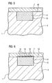
- FIG. 1 shows a layer system 1, which consists of at least one substrate 4 and at least one layer 7.
- the layer system 1 is for example a component of a steam or gas turbine 100 (blade 120, 130, combustion chamber lining 155,).
- the substrate 4 is therefore, for example, a nickel- or cobalt-based superalloy, i. metallic.
- the substrate 4 may also be ceramic.
- the coating 7 is ceramic or metallic and consists for example of an MCrAlX alloy.
- M is at least one element of the group Fe (iron), Co (cobalt) or Ni (nickel).
- X stands for yttrium and / or at least one element of the rare earths.
- the substrate 4 has a depression 10 (crack, recess, cutout), for example due to the long operational use of a component or due to the manner of manufacture.
- a proper coating of the substrate 4 is not yet possible in this state.
- the depression 10 is optionally cleaned beforehand (removal of oxides) and then filled with a first multicomponent material 13. This is, for example, a solder 13.
- Solders 13 contain, for example, as melting point lower components which react with the coating 7 at higher temperatures.
- Melting point depressants are often necessary to allow the solder to become low viscous and to penetrate well into a narrow crack and to completely fill up.
- the solder 13 contains boron (B) or boron-containing compounds which form chromium boride phases 16 with the chromium (Cr) of the MCrAlX layer 7, which are brittle and adversely affect the mechanical behavior and / or the anti-corrosion behavior.
- These undesirable phases 16 are formed by a reaction of at least one component (melting point depressants) of the first multicomponent material 13 with the coating 7 during a subsequent heat treatment or during operational use.
- boron diffuses into the coating 7 and / or chromium from the coating 7 into the depression 10 with the material 13.
- FIG. 2 shows a first step of the method according to the invention.
- the recess 10 is already filled with the solder 13 and possibly connected by a soldering heat treatment with the substrate 4.
- the melting point depressant in the material 13 is still desired to achieve bonding of the material 13 to the substrate 4 in the recess 10.
- the thickness of this layer of material 22 is, for example, thinner than the coating 7 still to be applied.
- the second material 22 is, for example, chromium, a chromium-containing compound or alloy or an alloy of other metals. Other materials are conceivable.
- the second material 22 may be applied by pastes, slips, tapes, plasma sprays, etc. having at least a high proportion of the second material 22.
- phase (connections) 16 ( Fig. 3 ), for example in the form of precipitates, as a result of which at least one undesirable component is removed from the first material 13, which with the coating 7 (FIG. Fig. 5 ) forms undesirable phases 16.
- Such phases are, for example, chromium borides, which form with the boron which is unbound even after the soldering heat treatment. Also interstitially (a grid) dissolved boron in the material 22 is conceivable.
- the phases 16 may form in the material 22 and / or in the material 13 in the recess 10.
- the material 22 is therefore for example a component of the coating 7, for example chromium of the MCrAlX coating. However, it is also possible to choose a material which contains no elements or constituents of the coating 7.
- a coating can in this state ( Fig. 6 ), because the second material 22 firmly binds the undesired components of the first material 13 in the form of compounds, as a result of which no or hardly any further reaction with the material of the coating 7 can take place.
- the coating with the material 22 also provides a diffusion barrier or threshold for still-diffusing undesirable components.
- the second material 22 and / or material 13 with the brittle phases 16 can also be removed (FIG. Fig. 4 ), in particular by grinding.
- the following heat treatments of the substrate 4 do not cause brittle phases in the coating 7, since the first material 13 hardly or at least in the vicinity of the surface 19 contains no unwanted components that react with the material of the coating 7 to undesirable compounds.
- the component thus produced may be a newly manufactured component or a used component. Especially in repair soldering of components (refurbishment), the method is used.
- defects are repaired after the process and optionally coated again, in particular with an MCrAlX and a ceramic thermal barrier coating thereon.
- FIG. 7 shows a gas turbine 100 in a longitudinal partial section.
- the gas turbine 100 has inside a rotatably mounted about a rotation axis 102 rotor 103, which is also referred to as a turbine runner.
- a compressor 105 for example a toroidal combustion chamber 110, in particular annular combustion chamber 106, with a plurality of coaxially arranged burners 107, a turbine 108 and the exhaust housing 109.
- the annular combustion chamber 106 communicates with an annular annular hot gas channel 111, for example.
- Each turbine stage 112 is formed from two blade rings.
- a series 125 formed of rotor blades 120 follows.
- the vanes 130 are attached to the stator 143, whereas the blades 120 of a row 125 are mounted on the rotor 103 by means of a turbine disk 133. Coupled to the rotor 103 is a generator or work machine (not shown).
- air 105 is sucked in and compressed by the compressor 105 through the intake housing 104.
- the compressed air provided at the turbine-side end of the compressor 105 is supplied to the burners 107 where it is mixed with a fuel.
- the mixture is then burned to form the working fluid 113 in the combustion chamber 110.
- the working medium 113 flows along the hot gas channel 111 past the guide vanes 130 and the rotor blades 120.
- the working medium 113 expands in a pulse-transmitting manner so that the rotor blades 120 drive the rotor 103 and drive the machine coupled to it.
- the components exposed to the hot working medium 113 are subject to thermal loads during operation of the gas turbine 100.
- the guide vanes 130 and rotor blades 120 of the first turbine stage 112, viewed in the direction of flow of the working medium 113, are subjected to the greatest thermal stress in addition to the heat shield bricks lining the annular combustion chamber 106. In order to withstand the temperatures prevailing there, they are cooled by means of a coolant.
- the vane 130 has a guide vane foot (not shown here) facing the inner casing 138 of the turbine 108 and a vane head opposite the vane root.
- the vane head faces the rotor 103 and fixed to a mounting ring 140 of the stator 143.
- FIG. 8 shows a combustion chamber 110 of a gas turbine.
- the combustion chamber 110 is configured, for example, as a so-called annular combustion chamber in which a plurality of circumferentially around the turbine shaft 103 arranged around Burners 102 open into a common combustion chamber space.
- the combustion chamber 110 is configured in its entirety as an annular structure, which is positioned around the turbine shaft 103 around.
- the combustion chamber 110 is designed for a comparatively high temperature of the working medium M of about 1000 ° C to 1600 ° C.
- the combustion chamber wall 153 is provided on its side facing the working medium M side with an inner lining formed from heat shield elements 155.
- Each heat shield element 155 is equipped on the working medium side with a particularly heat-resistant protective layer or made of high-temperature-resistant material. Due to the high temperatures in the interior of the combustion chamber 110, a cooling system is additionally provided for the heat shield elements 155 or for their holding elements.
- the combustion chamber 110 is designed in particular for detecting losses of the heat shield elements 155.
- a number of temperature sensors 158 are positioned between the combustion chamber wall 153 and the heat shield elements 155.
Landscapes
- Chemical & Material Sciences (AREA)
- Engineering & Computer Science (AREA)
- Mechanical Engineering (AREA)
- Metallurgy (AREA)
- Materials Engineering (AREA)
- Chemical Kinetics & Catalysis (AREA)
- Organic Chemistry (AREA)
- Inorganic Chemistry (AREA)
- Ceramic Engineering (AREA)
- Physics & Mathematics (AREA)
- Plasma & Fusion (AREA)
- General Engineering & Computer Science (AREA)
- Turbine Rotor Nozzle Sealing (AREA)
- Other Surface Treatments For Metallic Materials (AREA)
- Coating By Spraying Or Casting (AREA)
Abstract
Description
- Die Erfindung betrifft ein Verfahren zum Herstellen eines Schichtsystems nach dem Oberbegriff des Anspruchs 1 und Bauteil gemäss Anspruch 15.
- Turbinenschaufeln sowie andere Bauteile für Hochtemperaturanwendungen weisen nach langer Benutzung vielfach Risse oder Bereiche auf, in denen Korrosion auftrat, wobei diese Risse oder Bereiche im Rahmen einer Aufarbeitung der Bauteile entfernt werden müssen, wodurch dort jeweils eine Vertiefung entsteht.
- Die Risse oder die Vertiefung werden dann mit einem Lot aufgefüllt.
- Das mehrkomponentige Lot enthält u.a. Schmelzpunkterniedriger (z.B. Bor) oder andere Bestandteile, die, wie Untersuchungen im Rahmen der vorliegenden Erfindung ergeben haben, mit einer aufzutragenden abschließenden Beschichtung (z.B. Korrosionsschutzschicht, Wärmeschutzschicht) Sprödphasen (z.B. Chromborid) bilden.
- Solche Schichtsysteme weisen daher schlechte mechanische Eigenschaften, insbesondere bei hohen Temperaturen, auf.
- Auch wird die Oxidations- und Korrosionsschutzfunktion der Beschichtung verringert.
- Die
US 5,549,767 offenbart die Verwendung eines Reparaturmaterials, das den Schmelzpunkterniedriger Bor enthält, der zum Auffüllen von Rissen in einem Substrat verwendet wird. - Es ist daher Aufgabe der Erfindung ein Verfahren und ein Bauteil aufzuzeigen, das diese Eigenschaften des Schichtsystems mit einer unterliegenden aufgefüllten Vertiefung verbessert.
- Die Erfindung beruht auf der Erkenntnis, dass eine Komponente des Lots mit einer nachfolgend aufgebrachten Beschichtung in unerwünschter Weise reagiert.
- Die Aufgabe wird gelöst durch ein Verfahren gemäss Anspruch 1, indem in einem Zwischenschritt ein zweites Material aufgebracht wird, das mit dem ersten Material, beispielsweise einem Lot, beispielsweise reagiert und die unerwünschten Bestandteile des ersten Materials dadurch entzieht, dass es zumindest teilweise Verbindungen mit diesem bildet.
- Das zweite Material wird dann zusammen mit den aus dem ersten Material herausgelösten unerwünschten Bestandteilen wieder entfernt, also geopfert. So enthält die Begrenzungsfläche des ersten Materials zu der Beschichtung keine Bestandteile mehr, die mit dem Material einer noch aufzubringenden Beschichtung in unerwünschter Weise reagieren können.
- Das zweite Material kann aber auch das erste Material nur bedecken und einen Abstand zu der noch aufzubringenden Schicht schaffen, der eine Reaktion von Bestandteilen des ersten Materials mit der Beschichtung verhindert oder deutlich reduziert. Die Beschichtung aus dem zweiten Material stellt somit eine Diffusionsbarriere oder -schwelle dar.
- Die Aufgabe wird weiterhin gelöst durch ein Bauteil gemäss Anspruch 12.
- In den Unteransprüchen sind weitere vorteilhafte Maßnahmen aufgelistet.
- Die in den Unteransprüchen aufgelisteten Maßnahmen können in vorteilhafter Weise miteinander kombiniert werden.
- In den Figuren ist ein Ausführungsbeispiel erläutert.
- Es zeigen
- Figur 1
- ein Schichtsystem nach dem Stand der Technik,
- Figuren 2 bis 6
- Verfahrensschritte des erfindungsgemäßen Verfahrens,
- Figur 7
- eine Gasturbine,
- Figur 8
- eine Brennkammer und
- Figur 9
- eine Dampfturbine.
-
Figur 1 zeigt ein Schichtsystem 1, das zumindest aus einem Substrat 4 und zumindest einer Schicht 7 besteht. - Das Schichtsystem 1 ist beispielsweise ein Bauteil einer Dampf- oder Gas- 100 Turbine (Schaufel 120, 130, Brennkammerauskleidung 155,..).
- Das Substrat 4 ist daher beispielsweise eine nickel- oder kobaltbasierte Superlegierung, d.h. metallisch. Das Substrat 4 kann auch keramisch sein.
- Die Beschichtung 7 ist keramisch oder metallisch und besteht beispielsweise aus einer MCrAlX-Legierung.
- M steht für zumindest ein Element der Gruppe Fe (Eisen), Co (Kobalt) oder Ni (Nickel). X steht für Yttrium und/oder zumindest ein Element der Seltenen Erden.
- Das Substrat 4 weist eine Vertiefung 10 (Riss, Vertiefung, Ausfräsung) auf, beispielsweise bedingt durch den langen Betriebseinsatz eines Bauteils oder durch die Art der Herstellung.
- Eine ordnungsgemäße Beschichtung des Substrats 4 ist in diesem Zustand noch nicht möglich.
- Die Vertiefung 10 wird vorher gegebenenfalls gereinigt (Entfernung von Oxiden) und danach aufgefüllt mit einem ersten mehrkomponentigen Material 13. Dies ist beispielsweise ein Lot 13.
- Lote 13 enthalten beispielsweise als Schmelzpunkterniedriger Komponenten, die bei höheren Temperaturen mit der Beschichtung 7 reagieren.
- Schmelzpunkterniedriger sind oft notwendig, damit das Lot niedrigviskos wird und in einen schmalen Riss gut eindringen kann und vollständig auffüllt.
- Beispielsweise enthält das Lot 13 Bor (B) oder borhaltige Verbindungen, die mit dem Chrom (Cr) der MCrAlX-Schicht 7 Chromboridphasen 16 bilden, die spröd sind und das mechanische Verhalten und/oder das Korrosionsschutzverhalten negativ beeinflussen.
- Diese unerwünschten Phasen 16 bilden sich bei einer Reaktion von zumindest einer Komponente (Schmelzpunkterniedriger) des ersten mehrkomponentigen Materials 13 mit der Beschichtung 7 bei einer folgenden Wärmebehandlung oder während des betrieblichen Einsatzes.
- Dabei diffundiert Bor in die Beschichtung 7 und/oder Chrom aus der Beschichtung 7 in die Vertiefung 10 mit dem Material 13.
-
Figur 2 zeigt einen ersten Schritt des erfindungsgemäßen Verfahrens. - Die Vertiefung 10 ist bereits mit dem Lot 13 aufgefüllt und ggf. durch eine Lötwärmebehandlung mit dem Substrat 4 verbunden. Hier ist der Schmelzpunkterniedriger in dem Material 13 noch erwünscht, um eine Anbindung des Materials 13 an das Substrat 4 in der Vertiefung 10 zu erzielen.
- Auf einer Oberfläche 19 des Substrats 4 im Bereich der Vertiefung 10 wird ein zweites Material 22 aufgebracht und bildet eine lokale Beschichtung (Lokal bedeutet: Anteil der Fläche von 22 (= Querschnittsfläche Vertiefung 10) ist kleiner (<20%) als die Fläche der Beschichtung 7). Die Dicke dieser Schicht aus dem Material 22 ist beispielsweise dünner als die noch aufzubringende Beschichtung 7.
- Das zweite Material 22 ist beispielsweise Chrom, eine chromhaltige Verbindung oder Legierung oder eine Legierung anderer Metalle. Andere Materialien sind denkbar.
- Das zweite Material 22 kann durch Pasten, Schlicker, Bänder (Tapes), Plasmaspritzen usw. aufgebracht werden, die zumindest einen hohen Anteil des zweiten Materials 22 aufweisen.
- Durch eine Entfernungswärmebehandlung, insbesondere durch eine separate Diffusionswärmebehandlung bei hohen Temperaturen, aber alternativ beispielsweise auch gleichzeitig bei obiger Lötwärmebehandlung, bei der das Substrat 4 mit dem ersten Material 13 und dem zweiten Material 22 erhitzt wird, bilden sich Phasen (Verbindungen) 16 (
Fig. 3 ), beispielsweise in Form von Ausscheidungen, wodurch dem ersten Material 13 zumindest eine unerwünschte Komponente entzogen wird, die mit der noch aufzubringenden Beschichtung 7 (Fig. 5 ) unerwünschte Phasen 16 bildet. - Solche Phasen sind beispielsweise Chromboride, die sich mit dem noch nach der Lötwärmebehandlung ungebundenen Bor bilden. Auch interstitiell (ein Gitter) gelöstes Bor in dem Material 22 ist denkbar.
- Die Phasen 16 können sich in dem Material 22 und/oder in dem Material 13 in der Vertiefung 10 bilden.
- Das Material 22 ist daher beispielsweise ein Bestandteil der Beschichtung 7, beispielsweise Chrom der MCrAlX-Beschichtung. Es kann jedoch auch ein Material gewählt werden, das keine Elemente oder Bestandteile der Beschichtung 7 enthält.
- Es muss nur mit der zumindest einen unerwünschten Komponente des ersten Materials 13 reagieren können, die sonst mit der Beschichtung 7 in unerwünschter Weise reagieren würde.
- Eine Beschichtung kann in diesem Zustand (
Fig. 6 ) erfolgen, weil das zweite Material 22 die unerwünschten Komponenten des ersten Materials 13 in Form von Verbindungen fest bindet, wodurch keine oder kaum noch eine Reaktion mehr mit dem Material der Beschichtung 7 erfolgen kann. Die Beschichtung mit dem Material 22 stellt auch eine Diffusionsbarriere oder - schwelle für noch diffundierende unerwünschte Komponenten dar. - Das zweite Material 22 und/oder Material 13 mit den Sprödphasen 16 kann aber auch entfernt werden (
Fig. 4 ), insbesondere durch Abschleifen. - Danach erfolgt die Beschichtung 7 (
Fig. 5 ). - Auch durch folgende Wärmebehandlungen des Substrats 4 entstehen keine Sprödphasen in der Beschichtung 7, da das erste Material 13 zumindest in der Nähe der Oberfläche 19 kaum oder keine unerwünschten Komponenten mehr enthält, die mit dem Material der Beschichtung 7 zu unerwünschten Verbindungen reagieren.
- Das Bauteil, das so hergestellt wird, kann ein neu gefertigtes Bauteil oder ein gebrauchtes Bauteil sein. Insbesondere bei Reparaturlöten von Bauteilen (Refurbishment) findet das Verfahren seine Anwendung.
- Dabei findet vorab ein Entschichten statt. Die Fehler (Risse) werden nach dem Verfahren repariert und ggf. wieder beschichtet, insbesondere mit einer MCrAlX und einer keramischen Wärmedämmschicht darauf.
- Die
Figur 7 zeigt eine Gasturbine 100 in einem Längsteilschnitt. - Die Gasturbine 100 weist im Inneren einen um eine Rotationsachse 102 drehgelagerten Rotor 103 auf, der auch als Turbinenläufer bezeichnet wird. Entlang des Rotors 103 folgen aufeinander ein Ansauggehäuse 104, ein Verdichter 105, eine beispielsweise torusartige Brennkammer 110, insbesondere Ringbrennkammer 106, mit mehreren koaxial angeordneten Brennern 107, eine Turbine 108 und das Abgasgehäuse 109. Die Ringbrennkammer 106 kommuniziert mit einem beispielsweise ringförmigen Heißgaskanal 111. Dort bilden beispielsweise vier hintereinandergeschaltete Turbinenstufen 112 die Turbine 108. Jede Turbinenstufe 112 ist aus zwei Schaufelringen gebildet. In Strömungsrichtung eines Arbeitsmediums 113 gesehen folgt im Heißgaskanal 111 einer Leitschaufelreihe 115 eine aus Laufschaufeln 120 gebildete Reihe 125.
- Die Leitschaufeln 130 sind dabei am Stator 143 befestigt, wohingegen die Laufschaufeln 120 einer Reihe 125 mittels einer Turbinenscheibe 133 am Rotor 103 angebracht sind. An dem Rotor 103 angekoppelt ist ein Generator oder eine Arbeitsmaschine (nicht dargestellt).
- Während des Betriebes der Gasturbine 100 wird vom Verdichter 105 durch das Ansauggehäuse 104 Luft 135 angesaugt und verdichtet. Die am turbinenseitigen Ende des Verdichters 105 bereitgestellte verdichtete Luft wird zu den Brennern 107 geführt und dort mit einem Brennmittel vermischt. Das Gemisch wird dann unter Bildung des Arbeitsmediums 113 in der Brennkammer 110 verbrannt. Von dort aus strömt das Arbeitsmedium 113 entlang des Heißgaskanals 111 vorbei an den Leitschaufeln 130 und den Laufschaufeln 120. An den Laufschaufeln 120 entspannt sich das Arbeitsmedium 113 impulsübertragend, so dass die Laufschaufeln 120 den Rotor 103 antreiben und dieser die an ihn angekoppelte Arbeitsmaschine.
- Die dem heißen Arbeitsmedium 113 ausgesetzten Bauteile unterliegen während des Betriebes der Gasturbine 100 thermischen Belastungen. Die Leitschaufeln 130 und Laufschaufeln 120 der in Strömungsrichtung des Arbeitsmediums 113 gesehen ersten Turbinenstufe 112 werden neben den die Ringbrennkammer 106 auskleidenden Hitzeschildsteinen am meisten thermisch belastet. Um den dort herrschenden Temperaturen standzuhalten, werden diese mittels eines Kühlmittels gekühlt. Ebenso können die Schaufeln 120, 130 Beschichtungen gegen Korrosion (MCrAlX; M = Fe, Co, Ni, X=Y, Seltenen Erden) und Wärme (Wärmedämmschicht, beispielsweise ZrO2, Y2O4-ZrO2) aufweisen.
- Die Leitschaufel 130 weist einen dem Innengehäuse 138 der Turbine 108 zugewandten Leitschaufelfuß (hier nicht dargestellt) und einen dem Leitschaufelfuß gegenüberliegendem Leitschaufelkopf auf. Der Leitschaufelkopf ist dem Rotor 103 zugewandt und an einem Befestigungsring 140 des Stators 143 festgelegt.
- Die
Figur 8 zeigt eine Brennkammer 110 einer Gasturbine. - Die Brennkammer 110 ist beispielsweise als so genannte Ringbrennkammer ausgestaltet, bei der eine Vielzahl von in Umfangsrichtung um die Turbinenwelle 103 herum angeordneten Brennern 102 in einen gemeinsamen Brennkammerraum münden. Dazu ist die Brennkammer 110 in ihrer Gesamtheit als ringförmige Struktur ausgestaltet, die um die Turbinenwelle 103 herum positioniert ist.
- Zur Erzielung eines vergleichsweise hohen Wirkungsgrades ist die Brennkammer 110 für eine vergleichsweise hohe Temperatur des Arbeitsmediums M von etwa 1000°C bis 1600°C ausgelegt. Um auch bei diesen, für die Materialien ungünstigen Betriebsparametern eine vergleichsweise lange Betriebsdauer zu ermöglichen, ist die Brennkammerwand 153 auf ihrer dem Arbeitsmedium M zugewandten Seite mit einer aus Hitzeschildelementen 155 gebildeten Innenauskleidung versehen. Jedes Hitzeschildelement 155 ist arbeitsmediumsseitig mit einer besonders hitzebeständigen Schutzschicht ausgestattet oder aus hochtemperaturbeständigem Material gefertigt. Aufgrund der hohen Temperaturen im Inneren der Brennkammer 110 ist zudem für die Hitzeschildelemente 155 bzw. für deren Halteelemente ein Kühlsystem vorgesehen.
- Die Brennkammer 110 ist insbesondere für eine Detektion von Verlusten der Hitzeschildelemente 155 ausgelegt. Dazu sind zwischen der Brennkammerwand 153 und den Hitzeschildelementen 155 eine Anzahl von Temperatursensoren 158 positioniert.
Claims (18)
- Verfahren zum Herstellen eines Schichtsystems (1) mit einem Substrat (4),
wobei das Substrat (4) eine aufzufüllende Vertiefung (10) aufweist,
die mit einem ersten mehrkomponentigen Material (13) so aufgefüllt wird,
dass dann eine Beschichtung (7) des Substrats (4) im Bereich der aufgefüllten Vertiefung (10) erfolgen kann,
wobei das erste mehrkomponentige Material (13) zumindest eine unerwünschte Komponente enthält,
die eine Eigenschaft der Beschichtung (7) verschlechtert, wenn die zumindest eine unerwünschte Komponente in die Beschichtung (7) diffundiert,
dadurch gekennzeichnet,
dass in einem Zwischenschritt ein zweites Material (22) nur im Bereich der aufgefüllten Vertiefung (10) aufgebracht wird,
dass in einem Zwischenschritt eine Entfernungswärmebehandlung durchgeführt wird, sodass aus dem ersten mehrkomponentigen Material (13) in der Vertiefung zumindest eine unerwünschte Komponente zumindest teilweise in das zweite Material (22) gelangt, dass das zweite Material (22) zusammen mit der aus dem ersten Material (13) entfernten zumindest einen unerwünschten Komponente nach der Entfernungswärmebehandlung und vor der Beschichtung des Substrats (4) mit der Beschichtung (7) entfernt wird, insbesondere durch eine Schleifbehandlung,
so dass die unerwünschte Komponente kaum oder gar nicht mehr in die Beschichtung (7) diffundiert. - Verfahren nach Anspruch 1,
dadurch gekennzeichnet, dass
das erste mehrkomponentige Material (13) ein Lot ist,
das als zumindest eine Komponente zumindest einen Schmelzpunkterniedriger als unerwünschte Komponente aufweist. - Verfahren nach Anspruch 1,
dadurch gekennzeichnet, dass
der Schmelzpunkterniedriger aus Bor besteht oder Bor enthält. - Verfahren nach Anspruch 1,
dadurch gekennzeichnet, dass
mit dem ersten Material (13) vor dem Aufbringen der Beschichtung (7) eine Lötwärmebehandlung durchgeführt wird,
wodurch sich das erste Material (13) mit dem Substrat (4) in der Vertiefung (10) verbindet. - Verfahren nach Anspruch 1 oder 4,
dadurch gekennzeichnet, dass
als Entfernungswärmebehandlung eine Diffusionswärmebehandlung oder eine Lötwärmebehandlung durchgeführt wird. - Verfahren nach Anspruch 1,
dadurch gekennzeichnet, dass
als Substrat (4) eine Eisen-, Nickel- oder Kobalt-basierte Superlegierung verwendet wird. - Verfahren nach Anspruch 1,
dadurch gekennzeichnet, dass
als Beschichtung (7) eine MCrAlX-Legierung verwendet wird,
wobei M zumindest ein Element der Gruppe Fe, Co oder Ni ist,
und X Yttrium und/oder zumindest ein Element der Seltenen Erden ist. - Verfahren nach Anspruch 1,
dadurch gekennzeichnet, dass
die Schichtdicke der Beschichtung mit dem zweiten Material (22) im Vergleich zur Beschichtung (7) dünn ist. - Verfahren nach Anspruch 1,
dadurch gekennzeichnet, dass
als zweites Material (22) Chrom oder chromhaltige Verbindungen oder Legierungen verwendet werden. - Verfahren nach Anspruch 1,
dadurch gekennzeichnet,
dass das erste mehrkomponentige Material (13) zumindest eine unerwünschte Komponente enthält,
die eine unerwünschte Verbindung mit der Beschichtung (7) bildet,
und dass das zweite Material (22) während der Entfernungswärmebehandlung mit der zumindest einen unerwünschten Komponente des ersten mehrkomponentigen Materials (13) eine Verbindung bildet. - Verfahren nach Anspruch 1,
dadurch gekennzeichnet, dass
das zweite Material (22) durch eine Paste, einen Schlicker, ein Band oder andere Verfahren aufgebracht wird. - Bauteil,
das nach einem oder mehreren der Ansprüche 1 bis 11 hergestellt wurde und
das keine Schmelzpunkterniedriger aufweist. - Bauteil nach Anspruch 12,
dadurch gekennzeichnet, dass
das Bauteil ein Turbinenbauteil einer Gasturbine (100) oder Dampfturbine ist. - Bauteil nach Anspruch 12 oder 13,
dadurch gekennzeichnet, dass
das Bauteil (1) eine Turbinenschaufel (120, 130) ist. - Bauteil nach Anspruch 12 oder 13,
dadurch gekennzeichnet, dass
das Bauteil (1) eine Brennkammerauskleidung (155) ist. - Bauteil nach den Ansprüchen 12 bis 15,
dadurch gekennzeichnet, dass
das Bauteil (1) nach seinem Einsatz gemäß einem oder mehreren der Ansprüche 1 bis 11 wiederaufgearbeitet wird. - Bauteil nach den Ansprüchen 12 bis 16,
dadurch gekennzeichnet, dass
das Bauteil (1) ein Neubauteil ist. - Bauteil nach den Ansprüchen 12 bis 17,
dadurch gekennzeichnet, dass
das Bauteil (1) eine keramische Wärmedämmschicht aufweist.
Priority Applications (1)
| Application Number | Priority Date | Filing Date | Title |
|---|---|---|---|
| EP04765255A EP1670613B1 (de) | 2003-10-06 | 2004-09-15 | Verfahren zum herstellen eines schichtsystems |
Applications Claiming Priority (3)
| Application Number | Priority Date | Filing Date | Title |
|---|---|---|---|
| EP03022634A EP1522375A1 (de) | 2003-10-06 | 2003-10-06 | Verfahren zur Herstellung eines Schichtsystems |
| EP04765255A EP1670613B1 (de) | 2003-10-06 | 2004-09-15 | Verfahren zum herstellen eines schichtsystems |
| PCT/EP2004/010349 WO2005037483A1 (de) | 2003-10-06 | 2004-09-15 | Verfahren zum herstellen eines schichtsystems |
Publications (2)
| Publication Number | Publication Date |
|---|---|
| EP1670613A1 EP1670613A1 (de) | 2006-06-21 |
| EP1670613B1 true EP1670613B1 (de) | 2008-04-23 |
Family
ID=34306871
Family Applications (2)
| Application Number | Title | Priority Date | Filing Date |
|---|---|---|---|
| EP03022634A Withdrawn EP1522375A1 (de) | 2003-10-06 | 2003-10-06 | Verfahren zur Herstellung eines Schichtsystems |
| EP04765255A Expired - Lifetime EP1670613B1 (de) | 2003-10-06 | 2004-09-15 | Verfahren zum herstellen eines schichtsystems |
Family Applications Before (1)
| Application Number | Title | Priority Date | Filing Date |
|---|---|---|---|
| EP03022634A Withdrawn EP1522375A1 (de) | 2003-10-06 | 2003-10-06 | Verfahren zur Herstellung eines Schichtsystems |
Country Status (5)
| Country | Link |
|---|---|
| US (2) | US7736700B2 (de) |
| EP (2) | EP1522375A1 (de) |
| CN (1) | CN1863640B (de) |
| DE (1) | DE502004006948D1 (de) |
| WO (1) | WO2005037483A1 (de) |
Families Citing this family (9)
| Publication number | Priority date | Publication date | Assignee | Title |
|---|---|---|---|---|
| EP2078578A1 (de) * | 2008-01-10 | 2009-07-15 | Siemens Aktiengesellschaft | Belotung von Löchern, Verfahren zum Beschichten und Lotgutstäbchen |
| US8347636B2 (en) | 2010-09-24 | 2013-01-08 | General Electric Company | Turbomachine including a ceramic matrix composite (CMC) bridge |
| US8807955B2 (en) * | 2011-06-30 | 2014-08-19 | United Technologies Corporation | Abrasive airfoil tip |
| US20130259698A1 (en) * | 2012-03-28 | 2013-10-03 | General Electric Company | Method of Joining at Least Two Components, a Method for Rendering a Component Resistant to Eroision, and a Turbine Blade |
| EP3080321B1 (de) * | 2013-12-10 | 2019-07-31 | United Technologies Corporation | Verfahren zur elektroplattierung einer nickel-chrom-legierung |
| WO2015088876A1 (en) * | 2013-12-10 | 2015-06-18 | Lei Chen | Nickel-chromium-aluminum composite by electrodeposition |
| WO2015088861A1 (en) | 2013-12-11 | 2015-06-18 | Lei Chen | Electroformed nickel-chromium alloy |
| US20150321297A1 (en) | 2014-05-09 | 2015-11-12 | United Technologies Corporation | Systems and methods for repairing a surface of damaged metal components |
| US9845703B2 (en) * | 2014-12-12 | 2017-12-19 | General Electric Company | Turbine component surface treatment processes and systems |
Family Cites Families (16)
| Publication number | Priority date | Publication date | Assignee | Title |
|---|---|---|---|---|
| US2735155A (en) * | 1956-02-21 | With an excess of boron | ||
| US3573963A (en) * | 1966-07-05 | 1971-04-06 | United Aircraft Corp | Method of coating nickel base alloys with a mixture of tungsten and aluminum powders |
| US4275124A (en) * | 1978-10-10 | 1981-06-23 | United Technologies Corporation | Carbon bearing MCrAlY coating |
| GB2107628B (en) * | 1981-10-17 | 1985-08-21 | Rolls Royce | Improvements in or relating to filling fissures in metal articles |
| FR2599384B1 (fr) * | 1986-05-28 | 1988-08-05 | Alsthom | Procede de pose d'un revetement protecteur cobalt-chrome-tungstene sur une aube en alliage de titane comportant du vanadium et aube ainsi revetue |
| US4705203A (en) * | 1986-08-04 | 1987-11-10 | United Technologies Corporation | Repair of surface defects in superalloy articles |
| DE3816310A1 (de) * | 1987-06-26 | 1989-01-12 | Bbc Brown Boveri & Cie | Verfahren zur anreicherung von titan in der unmittelbaren oberflaechenzone eines bauteils aus einer mindestens 2,0 gew.-% titan enthaltenden nickelbasis-superlegierung und verwendung der nach dem verfahren angereicherten oberflaeche |
| US5156321A (en) * | 1990-08-28 | 1992-10-20 | Liburdi Engineering Limited | Powder metallurgy repair technique |
| WO1993022097A1 (en) * | 1992-05-06 | 1993-11-11 | United Technologies Corporation | Heat treatment and repair of cobalt-base superalloy articles |
| US5437737A (en) * | 1994-02-07 | 1995-08-01 | United Technologies Corporation | Repair coating for superalloy articles, such as gas turbine engine components |
| US5806751A (en) * | 1996-10-17 | 1998-09-15 | United Technologies Corporation | Method of repairing metallic alloy articles, such as gas turbine engine components |
| US6164916A (en) * | 1998-11-02 | 2000-12-26 | General Electric Company | Method of applying wear-resistant materials to turbine blades, and turbine blades having wear-resistant materials |
| US6283356B1 (en) * | 1999-05-28 | 2001-09-04 | General Electric Company | Repair of a recess in an article surface |
| JP2001288554A (ja) * | 2000-03-31 | 2001-10-19 | Toshiba Corp | 補修材料、耐熱合金部材の補修方法および本方法により補修された高温部品 |
| US6503349B2 (en) * | 2001-05-15 | 2003-01-07 | United Technologies Corporation | Repair of single crystal nickel based superalloy article |
| US7416108B2 (en) * | 2002-01-24 | 2008-08-26 | Siemens Power Generation, Inc. | High strength diffusion brazing utilizing nano-powders |
-
2003
- 2003-10-06 EP EP03022634A patent/EP1522375A1/de not_active Withdrawn
-
2004
- 2004-09-15 CN CN2004800292235A patent/CN1863640B/zh not_active Expired - Fee Related
- 2004-09-15 DE DE502004006948T patent/DE502004006948D1/de not_active Expired - Lifetime
- 2004-09-15 US US10/574,722 patent/US7736700B2/en not_active Expired - Fee Related
- 2004-09-15 WO PCT/EP2004/010349 patent/WO2005037483A1/de not_active Ceased
- 2004-09-15 EP EP04765255A patent/EP1670613B1/de not_active Expired - Lifetime
-
2010
- 2010-04-12 US US12/758,080 patent/US8017250B2/en not_active Expired - Fee Related
Also Published As
| Publication number | Publication date |
|---|---|
| US7736700B2 (en) | 2010-06-15 |
| EP1522375A1 (de) | 2005-04-13 |
| US20100192589A1 (en) | 2010-08-05 |
| EP1670613A1 (de) | 2006-06-21 |
| DE502004006948D1 (de) | 2008-06-05 |
| CN1863640B (zh) | 2010-06-16 |
| US20070059486A1 (en) | 2007-03-15 |
| WO2005037483A1 (de) | 2005-04-28 |
| CN1863640A (zh) | 2006-11-15 |
| US8017250B2 (en) | 2011-09-13 |
Similar Documents
| Publication | Publication Date | Title |
|---|---|---|
| EP1673490B1 (de) | Bauteil mit einer schutzschicht zum schutz des bauteils gegen korrosion und oxidation bei hohen temperaturen | |
| EP1866459B1 (de) | Matrix und schichtsystem | |
| EP2078579A1 (de) | Verfahren zum Löten eines Bauteils und Bauteil mit Löt- und Schweissstellen | |
| EP1522604B1 (de) | Schichtsystem und Verfahren zur Herstellung eines Schichtsystems | |
| EP1708829B1 (de) | Verfahren zur entfernung einer schicht | |
| US8017250B2 (en) | Method for production of a coating system | |
| DE102009031313A1 (de) | Beschichtung und Verfahren zum Beschichten eines Bauteils | |
| EP1998922B1 (de) | Verfahren zur funkenerosiven bearbeitung eines elektrisch nichtleitenden materials | |
| EP3068921A1 (de) | Verdichterschaufel mit erosionsbeständiger hartstoffbeschichtung | |
| EP2753729A1 (de) | Herstellungsverfahren eines schichtsystems | |
| EP1522373B1 (de) | Verfahren zur Herstellung eines Lochs | |
| EP1707301B1 (de) | Verfahren zum Aufbringen von Fasermatten auf die Oberfläche oder in eine Vertiefung eines Bauteiles | |
| EP1867423A1 (de) | Verfahren zum Reparieren eines Bauteils durch Verlöten eines mit Lot beschichteten Bleches | |
| WO2008087084A1 (de) | Pulvermischung mit blockigem pulver, verfahren zur verwendung der pulvermischung und bauteile | |
| EP1692322B1 (de) | Metallische schutzschicht | |
| EP1798299B1 (de) | Legierung, Schutzschicht und Bauteil | |
| EP1956105A1 (de) | Legierung, Schutzschicht zum Schutz eines Bauteils gegen Korrision und Oxidation bei hohen Temperaturen und Bauteil | |
| EP1772529A1 (de) | Trockene Zusammensetzung, Verwendung derer, Schichtsystem und Verfahren zur Beschichtung | |
| WO2007144217A1 (de) | Verfahren zum aufbringen von material auf ein bauteil | |
| EP1681374A1 (de) | Schichtsystem mit Sperrschicht und Verfahren zur Herstellung | |
| DE102004028672A1 (de) | Verfahren zum Beschichten von Innenflächen hohler Gasturbinenschaufeln | |
| EP1676938A1 (de) | Verfahren zur Herstellung eines Bauteils einer Turbine und ein Bauteil einer Turbine | |
| WO2007082787A1 (de) | Schweissverfahren mit anschliessender diffusionsbehandlung | |
| WO2007051752A1 (de) | Trockene zusammensetzung, deren verwendung, schichtsystem und verfahren zur beschichtung | |
| EP1918063A1 (de) | Komposit-Lötpulver aus Kern und metallischer Hülle, zum Löten von Turbinenbauteilen |
Legal Events
| Date | Code | Title | Description |
|---|---|---|---|
| PUAI | Public reference made under article 153(3) epc to a published international application that has entered the european phase |
Free format text: ORIGINAL CODE: 0009012 |
|
| 17P | Request for examination filed |
Effective date: 20060123 |
|
| AK | Designated contracting states |
Kind code of ref document: A1 Designated state(s): CH DE GB IT LI |
|
| 17Q | First examination report despatched |
Effective date: 20061016 |
|
| DAX | Request for extension of the european patent (deleted) | ||
| RBV | Designated contracting states (corrected) |
Designated state(s): CH DE GB IT LI |
|
| RIN1 | Information on inventor provided before grant (corrected) |
Inventor name: BAEHR, CHRISTIAN Inventor name: ANTON, REINER Inventor name: HEINECKE, BRIGITTE Inventor name: OTT, MICHAEL |
|
| GRAP | Despatch of communication of intention to grant a patent |
Free format text: ORIGINAL CODE: EPIDOSNIGR1 |
|
| GRAS | Grant fee paid |
Free format text: ORIGINAL CODE: EPIDOSNIGR3 |
|
| GRAA | (expected) grant |
Free format text: ORIGINAL CODE: 0009210 |
|
| AK | Designated contracting states |
Kind code of ref document: B1 Designated state(s): CH DE GB IT LI |
|
| REG | Reference to a national code |
Ref country code: GB Ref legal event code: FG4D Free format text: NOT ENGLISH |
|
| REG | Reference to a national code |
Ref country code: CH Ref legal event code: EP |
|
| REF | Corresponds to: |
Ref document number: 502004006948 Country of ref document: DE Date of ref document: 20080605 Kind code of ref document: P |
|
| REG | Reference to a national code |
Ref country code: CH Ref legal event code: NV Representative=s name: SIEMENS SCHWEIZ AG |
|
| PLBE | No opposition filed within time limit |
Free format text: ORIGINAL CODE: 0009261 |
|
| STAA | Information on the status of an ep patent application or granted ep patent |
Free format text: STATUS: NO OPPOSITION FILED WITHIN TIME LIMIT |
|
| REG | Reference to a national code |
Ref country code: CH Ref legal event code: PCAR Free format text: SIEMENS SCHWEIZ AG;INTELLECTUAL PROPERTY FREILAGERSTRASSE 40;8047 ZUERICH (CH) |
|
| 26N | No opposition filed |
Effective date: 20090126 |
|
| PGFP | Annual fee paid to national office [announced via postgrant information from national office to epo] |
Ref country code: DE Payment date: 20101119 Year of fee payment: 7 |
|
| PGFP | Annual fee paid to national office [announced via postgrant information from national office to epo] |
Ref country code: IT Payment date: 20100928 Year of fee payment: 7 |
|
| PGFP | Annual fee paid to national office [announced via postgrant information from national office to epo] |
Ref country code: GB Payment date: 20110915 Year of fee payment: 8 |
|
| PGFP | Annual fee paid to national office [announced via postgrant information from national office to epo] |
Ref country code: CH Payment date: 20111213 Year of fee payment: 8 |
|
| REG | Reference to a national code |
Ref country code: CH Ref legal event code: PL |
|
| GBPC | Gb: european patent ceased through non-payment of renewal fee |
Effective date: 20120915 |
|
| PG25 | Lapsed in a contracting state [announced via postgrant information from national office to epo] |
Ref country code: GB Free format text: LAPSE BECAUSE OF NON-PAYMENT OF DUE FEES Effective date: 20120915 Ref country code: CH Free format text: LAPSE BECAUSE OF NON-PAYMENT OF DUE FEES Effective date: 20120930 Ref country code: LI Free format text: LAPSE BECAUSE OF NON-PAYMENT OF DUE FEES Effective date: 20120930 Ref country code: DE Free format text: LAPSE BECAUSE OF NON-PAYMENT OF DUE FEES Effective date: 20130403 |
|
| PG25 | Lapsed in a contracting state [announced via postgrant information from national office to epo] |
Ref country code: IT Free format text: LAPSE BECAUSE OF NON-PAYMENT OF DUE FEES Effective date: 20120915 |
|
| REG | Reference to a national code |
Ref country code: DE Ref legal event code: R119 Ref document number: 502004006948 Country of ref document: DE Effective date: 20130403 |