EP1670548B1 - Heart stimulation device - Google Patents
Heart stimulation device Download PDFInfo
- Publication number
- EP1670548B1 EP1670548B1 EP03818737A EP03818737A EP1670548B1 EP 1670548 B1 EP1670548 B1 EP 1670548B1 EP 03818737 A EP03818737 A EP 03818737A EP 03818737 A EP03818737 A EP 03818737A EP 1670548 B1 EP1670548 B1 EP 1670548B1
- Authority
- EP
- European Patent Office
- Prior art keywords
- ventricle
- stimulation
- evoked response
- stimulated
- time window
- Prior art date
- Legal status (The legal status is an assumption and is not a legal conclusion. Google has not performed a legal analysis and makes no representation as to the accuracy of the status listed.)
- Expired - Lifetime
Links
- 230000000638 stimulation Effects 0.000 title claims description 51
- 230000004044 response Effects 0.000 claims description 32
- 238000001514 detection method Methods 0.000 claims description 28
- 230000000763 evoking effect Effects 0.000 claims description 26
- 230000002861 ventricular Effects 0.000 claims description 11
- 230000002401 inhibitory effect Effects 0.000 claims description 8
- 230000000747 cardiac effect Effects 0.000 claims description 5
- 238000010586 diagram Methods 0.000 description 7
- 210000005241 right ventricle Anatomy 0.000 description 6
- 210000005240 left ventricle Anatomy 0.000 description 5
- 230000001746 atrial effect Effects 0.000 description 4
- 208000033986 Device capturing issue Diseases 0.000 description 3
- 206010006580 Bundle branch block left Diseases 0.000 description 2
- 206010006582 Bundle branch block right Diseases 0.000 description 2
- 230000006870 function Effects 0.000 description 2
- 238000000034 method Methods 0.000 description 2
- 210000005242 cardiac chamber Anatomy 0.000 description 1
- 238000004891 communication Methods 0.000 description 1
- 210000003748 coronary sinus Anatomy 0.000 description 1
- 238000013480 data collection Methods 0.000 description 1
- 230000001934 delay Effects 0.000 description 1
- 238000005265 energy consumption Methods 0.000 description 1
- 210000002837 heart atrium Anatomy 0.000 description 1
- 210000005246 left atrium Anatomy 0.000 description 1
- 230000004936 stimulating effect Effects 0.000 description 1
- 230000001360 synchronised effect Effects 0.000 description 1
Images




Classifications
-
- A—HUMAN NECESSITIES
- A61—MEDICAL OR VETERINARY SCIENCE; HYGIENE
- A61N—ELECTROTHERAPY; MAGNETOTHERAPY; RADIATION THERAPY; ULTRASOUND THERAPY
- A61N1/00—Electrotherapy; Circuits therefor
- A61N1/18—Applying electric currents by contact electrodes
- A61N1/32—Applying electric currents by contact electrodes alternating or intermittent currents
- A61N1/36—Applying electric currents by contact electrodes alternating or intermittent currents for stimulation
- A61N1/362—Heart stimulators
- A61N1/37—Monitoring; Protecting
- A61N1/371—Capture, i.e. successful stimulation
-
- A—HUMAN NECESSITIES
- A61—MEDICAL OR VETERINARY SCIENCE; HYGIENE
- A61N—ELECTROTHERAPY; MAGNETOTHERAPY; RADIATION THERAPY; ULTRASOUND THERAPY
- A61N1/00—Electrotherapy; Circuits therefor
- A61N1/18—Applying electric currents by contact electrodes
- A61N1/32—Applying electric currents by contact electrodes alternating or intermittent currents
- A61N1/36—Applying electric currents by contact electrodes alternating or intermittent currents for stimulation
- A61N1/362—Heart stimulators
- A61N1/365—Heart stimulators controlled by a physiological parameter, e.g. heart potential
- A61N1/368—Heart stimulators controlled by a physiological parameter, e.g. heart potential comprising more than one electrode co-operating with different heart regions
-
- A—HUMAN NECESSITIES
- A61—MEDICAL OR VETERINARY SCIENCE; HYGIENE
- A61N—ELECTROTHERAPY; MAGNETOTHERAPY; RADIATION THERAPY; ULTRASOUND THERAPY
- A61N1/00—Electrotherapy; Circuits therefor
- A61N1/18—Applying electric currents by contact electrodes
- A61N1/32—Applying electric currents by contact electrodes alternating or intermittent currents
- A61N1/36—Applying electric currents by contact electrodes alternating or intermittent currents for stimulation
- A61N1/362—Heart stimulators
- A61N1/365—Heart stimulators controlled by a physiological parameter, e.g. heart potential
- A61N1/368—Heart stimulators controlled by a physiological parameter, e.g. heart potential comprising more than one electrode co-operating with different heart regions
- A61N1/3684—Heart stimulators controlled by a physiological parameter, e.g. heart potential comprising more than one electrode co-operating with different heart regions for stimulating the heart at multiple sites of the ventricle or the atrium
- A61N1/36843—Bi-ventricular stimulation
-
- A—HUMAN NECESSITIES
- A61—MEDICAL OR VETERINARY SCIENCE; HYGIENE
- A61N—ELECTROTHERAPY; MAGNETOTHERAPY; RADIATION THERAPY; ULTRASOUND THERAPY
- A61N1/00—Electrotherapy; Circuits therefor
- A61N1/18—Applying electric currents by contact electrodes
- A61N1/32—Applying electric currents by contact electrodes alternating or intermittent currents
- A61N1/36—Applying electric currents by contact electrodes alternating or intermittent currents for stimulation
- A61N1/362—Heart stimulators
- A61N1/365—Heart stimulators controlled by a physiological parameter, e.g. heart potential
- A61N1/368—Heart stimulators controlled by a physiological parameter, e.g. heart potential comprising more than one electrode co-operating with different heart regions
- A61N1/3684—Heart stimulators controlled by a physiological parameter, e.g. heart potential comprising more than one electrode co-operating with different heart regions for stimulating the heart at multiple sites of the ventricle or the atrium
Definitions
- the present invention relates to a biventricular stimulation device comprising a pulse generator for delivering stimulation pulses at least to the ventricles of a patient's heart, and an evoked response detector having first and second, independent ventricular sensing channels for ventricular evoked response detection in the ventricles, said pulse generator being controlled to deliver said stimulation pulses to the second ventricle with a VV time delay after stimulation pulse delivery to the first stimulated ventricle which is shorter than an evoked response detection time window following delivery of a stimulation pulse to the first stimulated ventricle.
- the ventricle set to be stimulated first is referred to as “the first ventricle”
- the ventricle that is set to be stimulated second is referred to as “the second ventricle”.
- ERW evoked response time window
- the evoked response time window, ERW for the first stimulated ventricle will be interrupted by a stimulation pulse delivered to the second ventricle, i.e. the last stimulated ventricle of the heart.
- beat-to-beat evoked response, ER detection on the first ventricle is impossible with such a short VV time delay.
- the purpose of the present invention is to utilize this possibility for providing a biventricular stimulation device with an improved possibility to ER detection in the first ventricle despite a short VV time delay.
- biventricular stimulation device of the kind defined in the introductory portion and having the characterizing features of claim 1.
- the left ventricle is the first stimulated heart chamber and the right ventricle the second one, since LBBB is much more frequent than RBBB.
- An intrinsic R wave originating from e.g. a conducted P wave will thus be sensed in the right ventricle, probably shortly after the stimulation pulse is delivered to the left ventricle.
- an ERW is always started after each one of the stimulation pulses to the first ventricle even when a short VV time delays is programmed.
- the evoked response detector of the stimulation device is then arranged to close the ERW or discard detections therein in response to the emission of a stimulation pulse to the second ventricle during the ERW of the first stimulated ventricle.
- the evoked response detector is provided with first and second, independent ventricular sensing channels for ventricular evoked response detection in the respective ventricles, as in for instance Epic HF.
- an inhibiting means for inhibiting stimulation in the second ventricle in response to the detection of a sensed intrinsic cardiac event therein, and the VV time delay is less than 40 msec, preferably in the range of 10-30 msec, and the duration of ERW is in the range of 40-100 msec.
- figure 1 illustrates typical placements in the heart of the leads of a stimulation device according to the invention having also an atrial lead implanted
- figure 2 is a block diagram of the main electronic circuitry units of a stimulation device like the pacemaker shown in figure 1
- figure 3 is a block diagram illustrating the input/output stage in figure 2 in greater detail
- figure 4 is a flow diagram illustrating the function of the embodiment described in connection with the preceding figures
- figure 5 is a timing diagram further illustrating the function of the described embodiment of the device according to the invention.
- FIG. 1 shows a heart stimulation device in the form of a pacemaker 10 having an atrial 20 and two ventricular leads 24, 30 for stimulating and independently sensing in the left atrium and the ventricles of the heart 12.
- the figure shows typical positions for an atrial electrode 22, right ventricular electrodes 32, 34 and a left ventricular electrode 26 placed in the coronary sinus.
- the biventricular pacing lead configuration comprises an unipolär left ventricular lead 24, 26 and a bipolar right ventricular lead 30, 32, 34.
- FIG 2 is an electronic circuitry block diagram of the main units of the pacemaker 10 in figure 1.
- the implanted leads 20, 24, 30 in figure are connected to an input/output stage 40 in the pacemaker 10.
- the stage 40 comprises a pacing and a sensing module as will be further described in connection with figure 3.
- the operation on the pacemaker is controlled by a CPU 42.
- the pacemaker also includes a memory 44 for storing information about e.g. how the stimulation threshold has changed over time, how much stimulation has been given, energy consumption etc. which is read out at follow ups.
- Telemetry means 46 are provided for the communication between the implanted pacemaker and an external programmer.
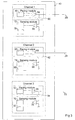
- the input/output stage 40 to which the leads 20, 24 and 30 are connected is shown in a larger scale in figure 3.
- this stage 40 comprises three channels, one lead 20, 24, and 30 respectively being connected to each of the channels.
- Each channel comprises a pacing module and a sensing module, and each pacing module includes a pacing stage 48, 50, 52 connected to an amplifier 54, 56, 58.
- the leads 20, 24, 30 are connected to the outputs of the amplifiers 54, 56, 58 for delivering stimulation pulses to the patient's heart as controlled from the CPU 42.
- the leads 20, 24, 30 are also used for sensing signals in the heart and can be connected, via switches 60, 62, 64 to the sensing module of each channel.
- Each sensing module includes an amplifier 66, 68, 70 in which sensed signals are amplified and the amplified signals are then supplied to an event detector 72, 74, 76 and ER detector 78, 80, 82 for detecting possible evoked response of the heart. It is important that the three channels for stimulation and sensing are separated.
- the switches 60, 62, 64 are controlled to disconnect all sensing modules whenever a stimulation pulse is delivered on anyone of the channels to avoid that the stimulation give rise to disturbances and saturation in the sensing modules.
- the switches 60, 62, 64 are controlled to otherwise connect the sensing modules to their respective lead 20, 24, 30.
- the CPU 42 comprises an inhibiting means for inhibiting stimulation in the second ventricle, e.g. the right ventricle, in response to the detection by the associated sensing module of a sensed cardiac event therein within the VV time delay.
- the evoked response detector is arranged to close the evoked response detection time window of the first ventricle or discard detections therein in response to the emission of a stimulation pulse to the second ventricle, during the evoked response detection time window of the first stimulated ventricle.
- a command is given triggering stimulation of the first ventricle V1.
- Collection of data for evoked response, ER, detection in the first ventricle is started, block 84. If no cardiac event, like an R wave, R2, is detected in the second ventricle within the predetermined VV time delay, blocks 86 and 88, a stimulation pulse is delivered to the second ventricle V2, block 90.
- the connection of ER 1 data is then aborted, block 92, and possible resulting evoked response ER 2 is evaluated and the main procedure is continued.
- a cardiac event in the second ventricle, R2 is detected before the expire of the VV time delay stimulation to the second ventricle, V2, is inhibited by the inhibiting means, block 94. If the collection of evoked response data ER1 from the first ventricle is then completed, block 96, these data are evaluated for detection of possible evoked response, block 98, otherwise this ER1 data collection is repeated or continued till completion, cf. block 96. After terminated evoked response detection in the first ventricle the main procedure is repeated.
- Line A relates to the atrium and lines LV and RV to the left and right ventricles respectively. P-waves are shown at 100, 102.
- the left ventricle LV is first stimulated at 104 and an evoked response detection time window ERW 106 is following this stimulation pulse 104. If a stimulation pulse 107 is delivered to the second ventricle RV the ERW of the first ventricle 106 will be closed and the results discarded. No decision concerning capture or loss of capture will then be taken.
- the stimulation pulse 107 to the right second ventricle is followed by an ERW 108 for detection of capture or loss of capture in normal way.
- an intrinsic R wave 110 is detected in the second ventricle RV, e.g. originating from a conducted P wave 102, this intrinsic R wave 110 will be sensed in the second ventricle RV, probably shortly after the stimulation pulse in the first ventricle LV.
- the sensed R wave 110 in the second ventricle RV will then control the inhibiting means to inhibit the second stimulation pulse 114 and ER detection in the associated ERW 112 of the first ventricle LV is performed.
- the inhibiting means to inhibit the second stimulation pulse 114 and ER detection in the associated ERW 112 of the first ventricle LV is performed.
- the example above relates to patients for which the LV stimulation is programmed to come first, e.g. most LBBB patients. For most RBBB patients the situation will be analogous with first and second ventricles shifted
Landscapes
- Health & Medical Sciences (AREA)
- Cardiology (AREA)
- Heart & Thoracic Surgery (AREA)
- Life Sciences & Earth Sciences (AREA)
- Radiology & Medical Imaging (AREA)
- Nuclear Medicine, Radiotherapy & Molecular Imaging (AREA)
- Biomedical Technology (AREA)
- Engineering & Computer Science (AREA)
- Animal Behavior & Ethology (AREA)
- General Health & Medical Sciences (AREA)
- Public Health (AREA)
- Veterinary Medicine (AREA)
- Biophysics (AREA)
- Physiology (AREA)
- Electrotherapy Devices (AREA)
Description
- The present invention relates to a biventricular stimulation device comprising a pulse generator for delivering stimulation pulses at least to the ventricles of a patient's heart, and an evoked response detector having first and second, independent ventricular sensing channels for ventricular evoked response detection in the ventricles, said pulse generator being controlled to deliver said stimulation pulses to the second ventricle with a VV time delay after stimulation pulse delivery to the first stimulated ventricle which is shorter than an evoked response detection time window following delivery of a stimulation pulse to the first stimulated ventricle.
- In the following the ventricle set to be stimulated first is referred to as "the first ventricle", and the ventricle that is set to be stimulated second as "the second ventricle". Even though there is a difference both in stimulation threshold and amplitude of intrinsic signals for the left and the right ventricles, there will be no difference in stimulation strategy if the left or right ventricle is stimulated first. The terms "first" and "second" are only related to the programming of the stimulation device.
- In a biventricular pacemaker with a comparatively short VV time delay of less than e.g. 40 msec the evoked response time window, ERW, for the first stimulated ventricle will be interrupted by a stimulation pulse delivered to the second ventricle, i.e. the last stimulated ventricle of the heart. Thus beat-to-beat evoked response, ER, detection on the first ventricle is impossible with such a short VV time delay.
- However, in some cases ER detection is possible on the first ventricle regardless of a short VV time delay as mentioned above.
- The purpose of the present invention is to utilize this possibility for providing a biventricular stimulation device with an improved possibility to ER detection in the first ventricle despite a short VV time delay.
- This purpose is obtained by a biventricular stimulation device of the kind defined in the introductory portion and having the characterizing features of
claim 1. - For a normal stimulation pattern in biventricular stimulation devices the left ventricle is the first stimulated heart chamber and the right ventricle the second one, since LBBB is much more frequent than RBBB. An intrinsic R wave originating from e.g. a conducted P wave will thus be sensed in the right ventricle, probably shortly after the stimulation pulse is delivered to the left ventricle. In the stimulation device according to the invention an ERW is always started after each one of the stimulation pulses to the first ventricle even when a short VV time delays is programmed. The evoked response detector of the stimulation device is then arranged to close the ERW or discard detections therein in response to the emission of a stimulation pulse to the second ventricle during the ERW of the first stimulated ventricle. Thus, only if there is emitted a stimulation pulse to the second ventricle no decision concerning capture or loss of capture of the first ventricle will be taken. An important feature of the stimulation device according to the invention is that the evoked response detector is provided with first and second, independent ventricular sensing channels for ventricular evoked response detection in the respective ventricles, as in for instance Epic HF.
- According to advantageous embodiments of the device according to the invention an inhibiting means is provided for inhibiting stimulation in the second ventricle in response to the detection of a sensed intrinsic cardiac event therein, and the VV time delay is less than 40 msec, preferably in the range of 10-30 msec, and the duration of ERW is in the range of 40-100 msec.
- To further explain the invention an embodiment of the device according to the invention will be described in greater detail with reference to the accompanying drawings on which figure 1 illustrates typical placements in the heart of the leads of a stimulation device according to the invention having also an atrial lead implanted, figure 2 is a block diagram of the main electronic circuitry units of a stimulation device like the pacemaker shown in figure 1, figure 3 is a block diagram illustrating the input/output stage in figure 2 in greater detail, figure 4 is a flow diagram illustrating the function of the embodiment described in connection with the preceding figures, and figure 5 is a timing diagram further illustrating the function of the described embodiment of the device according to the invention.
- Figure 1 shows a heart stimulation device in the form of a
pacemaker 10 having an atrial 20 and two ventricular leads 24, 30 for stimulating and independently sensing in the left atrium and the ventricles of theheart 12. The figure shows typical positions for anatrial electrode 22, rightventricular electrodes ventricular electrode 26 placed in the coronary sinus. The biventricular pacing lead configuration comprises an unipolär leftventricular lead ventricular lead atrial lead - Figure 2 is an electronic circuitry block diagram of the main units of the
pacemaker 10 in figure 1. The implanted leads 20, 24, 30 in figure are connected to an input/output stage 40 in thepacemaker 10. Thestage 40 comprises a pacing and a sensing module as will be further described in connection with figure 3. The operation on the pacemaker is controlled by aCPU 42. The pacemaker also includes amemory 44 for storing information about e.g. how the stimulation threshold has changed over time, how much stimulation has been given, energy consumption etc. which is read out at follow ups. Telemetry means 46 are provided for the communication between the implanted pacemaker and an external programmer. - The input/
output stage 40 to which theleads stage 40 comprises three channels, onelead pacing stage amplifier leads amplifiers CPU 42. - The
leads switches amplifier event detector ER detector - The
switches switches respective lead - The
CPU 42 comprises an inhibiting means for inhibiting stimulation in the second ventricle, e.g. the right ventricle, in response to the detection by the associated sensing module of a sensed cardiac event therein within the VV time delay. The evoked response detector is arranged to close the evoked response detection time window of the first ventricle or discard detections therein in response to the emission of a stimulation pulse to the second ventricle, during the evoked response detection time window of the first stimulated ventricle. - The operation of the above embodiment of the stimulation device according to the invention is illustrated by a flow diagram in figure 4. Thus a command is given triggering stimulation of the first ventricle V1. Collection of data for evoked response, ER, detection in the first ventricle is started,
block 84. If no cardiac event, like an R wave, R2, is detected in the second ventricle within the predetermined VV time delay,blocks block 90. The connection ofER 1 data is then aborted,block 92, and possible resulting evokedresponse ER 2 is evaluated and the main procedure is continued. - If a cardiac event in the second ventricle, R2, is detected before the expire of the VV time delay stimulation to the second ventricle, V2, is inhibited by the inhibiting means,
block 94. If the collection of evoked response data ER1 from the first ventricle is then completed,block 96, these data are evaluated for detection of possible evoked response,block 98, otherwise this ER1 data collection is repeated or continued till completion, cf.block 96. After terminated evoked response detection in the first ventricle the main procedure is repeated. - An example of the operation of the device according to the invention is also illustrated by a timing diagram in figure 5. Line A relates to the atrium and lines LV and RV to the left and right ventricles respectively. P-waves are shown at 100, 102. The left ventricle LV is first stimulated at 104 and an evoked response detection
time window ERW 106 is following thisstimulation pulse 104. If astimulation pulse 107 is delivered to the second ventricle RV the ERW of thefirst ventricle 106 will be closed and the results discarded. No decision concerning capture or loss of capture will then be taken. - The
stimulation pulse 107 to the right second ventricle is followed by anERW 108 for detection of capture or loss of capture in normal way. - If an
intrinsic R wave 110 is detected in the second ventricle RV, e.g. originating from a conductedP wave 102, thisintrinsic R wave 110 will be sensed in the second ventricle RV, probably shortly after the stimulation pulse in the first ventricle LV. Thesensed R wave 110 in the second ventricle RV will then control the inhibiting means to inhibit thesecond stimulation pulse 114 and ER detection in the associatedERW 112 of the first ventricle LV is performed. Thus, to sum up, if a RV stimulation pulse is emitted during the LV evoked response detection time window no ER detection is performed in LV, else ER detection will always be performed in LV. - The example above relates to patients for which the LV stimulation is programmed to come first, e.g. most LBBB patients. For most RBBB patients the situation will be analogous with first and second ventricles shifted
Claims (4)
- A biventricular stimulation device comprising a pulse generator for delivering stimulation pulses at least to the ventricles of a patient's heart, and an evoked response detector having independent, first and second ventricular sensing channels for ventricular evoked response detection in the ventricles, said pulse generator being controlled to deliver said stimulation pulses to the second ventricle with a time delay after stimulation pulse delivery to the first stimulated ventricle which is shorter than an evoked response detection time window following delivery of a stimulation pulse to the first stimulated ventricle, characterized in that said evoked response detector is arranged to close said evoked response detection time window or discard detections therein in response to the emission of a stimulation pulse to the second ventricle during said evoked response detection time window of the first stimulated ventricle.
- The device according to claim 1, characterized in that an inhibiting means is provided for inhibiting stimulation in the second ventricle in response to the detection of a sensed intrinsic cardiac event therein.
- The device according to claim 1 or 2, characterized in that said time delay is less than 40 msec, preferably in the range of 10 - 30 msec.
- The device according to any of the preceding claims, characterized in that the duration of said evoked response detection time window is in the range of 40 - 100 msec.
Applications Claiming Priority (1)
| Application Number | Priority Date | Filing Date | Title |
|---|---|---|---|
| PCT/SE2003/001494 WO2005028030A1 (en) | 2003-09-25 | 2003-09-25 | Heart stimulation device |
Publications (2)
| Publication Number | Publication Date |
|---|---|
| EP1670548A1 EP1670548A1 (en) | 2006-06-21 |
| EP1670548B1 true EP1670548B1 (en) | 2008-01-09 |
Family
ID=34374514
Family Applications (1)
| Application Number | Title | Priority Date | Filing Date |
|---|---|---|---|
| EP03818737A Expired - Lifetime EP1670548B1 (en) | 2003-09-25 | 2003-09-25 | Heart stimulation device |
Country Status (5)
| Country | Link |
|---|---|
| US (1) | US7353061B2 (en) |
| EP (1) | EP1670548B1 (en) |
| AU (1) | AU2003263723A1 (en) |
| DE (1) | DE60318635T2 (en) |
| WO (1) | WO2005028030A1 (en) |
Families Citing this family (8)
| Publication number | Priority date | Publication date | Assignee | Title |
|---|---|---|---|---|
| US7286876B2 (en) * | 2001-10-26 | 2007-10-23 | Cardiac Pacemakers, Inc. | Template-based capture verification for multi-site pacing |
| US7113823B2 (en) * | 2001-10-26 | 2006-09-26 | Cardiac Pacemakers, Inc. | Morphology-based optimization of cardiac resynchronization therapy |
| US7177689B2 (en) | 2001-10-26 | 2007-02-13 | Cardiac Pacemakers, Inc. | Method and apparatus for capture verification and threshold determination |
| US7555340B2 (en) * | 2005-04-01 | 2009-06-30 | Cardiac Pacemakers, Inc. | Electrogram morphology-based CRT optimization |
| EP1945301B1 (en) * | 2005-10-31 | 2011-12-14 | St. Jude Medical AB | An implantable heart stimulating device |
| US7546161B1 (en) * | 2006-01-11 | 2009-06-09 | Pacesetter, Inc. | Methods for loss of capture and fusion avoidance in biventricular pacing therapy |
| US9020596B2 (en) | 2011-07-15 | 2015-04-28 | Cardiac Pacemakers, Inc. | Management of fusion beat detection during capture threshold determination |
| WO2017173402A2 (en) | 2016-03-31 | 2017-10-05 | Novinium, Inc. | Smart system for manhole event suppression system |
Family Cites Families (7)
| Publication number | Priority date | Publication date | Assignee | Title |
|---|---|---|---|---|
| US6148234A (en) * | 1998-09-28 | 2000-11-14 | Medtronic Inc. | Dual site pacing system with automatic pulse output adjustment |
| US6615089B1 (en) | 2000-03-31 | 2003-09-02 | Cardiac Pacemakers, Inc. | System and method for verifying capture in a multi-site pacemaker |
| US20010049543A1 (en) * | 2000-05-15 | 2001-12-06 | Kroll Mark W. | Method and apparatus for biventricular stimulation and capture monitoring |
| US6549806B1 (en) | 2000-05-15 | 2003-04-15 | Pacesetter, Inc. | Implantable dual site cardiac stimulation device having independent automatic capture capability |
| US6587723B1 (en) * | 2000-10-17 | 2003-07-01 | Pacesetter, Inc. | Method and system for automatically measuring capture threshold in an implantable cardiac stimulation device |
| US6522921B2 (en) * | 2000-12-26 | 2003-02-18 | Cardiac Pacemakers, Inc. | System and method for eliminating cross-talk due to far-field signals |
| US6915164B2 (en) * | 2002-04-16 | 2005-07-05 | Pacesetter, Inc. | Automatic capture using independent channels in bi-chamber stimulation |
-
2003
- 2003-09-25 EP EP03818737A patent/EP1670548B1/en not_active Expired - Lifetime
- 2003-09-25 WO PCT/SE2003/001494 patent/WO2005028030A1/en not_active Ceased
- 2003-09-25 DE DE60318635T patent/DE60318635T2/en not_active Expired - Lifetime
- 2003-09-25 US US10/573,281 patent/US7353061B2/en not_active Expired - Fee Related
- 2003-09-25 AU AU2003263723A patent/AU2003263723A1/en not_active Abandoned
Also Published As
| Publication number | Publication date |
|---|---|
| DE60318635D1 (en) | 2008-02-21 |
| US7353061B2 (en) | 2008-04-01 |
| WO2005028030A1 (en) | 2005-03-31 |
| EP1670548A1 (en) | 2006-06-21 |
| DE60318635T2 (en) | 2009-01-02 |
| US20070055312A1 (en) | 2007-03-08 |
| AU2003263723A1 (en) | 2005-04-11 |
Similar Documents
| Publication | Publication Date | Title |
|---|---|---|
| US7047073B2 (en) | Cardiac stimulating device | |
| US7260432B2 (en) | Timing cycles for synchronized multisite cardiac pacing | |
| US7697977B2 (en) | Method and apparatus for determining relative depolarization at multiple cardiac sensing sites | |
| US6456881B1 (en) | System and method of identifying fusion for dual-chamber automatic capture stimulation device | |
| US6915164B2 (en) | Automatic capture using independent channels in bi-chamber stimulation | |
| EP1284786B1 (en) | Apparatus and method for controlling the delivery of non-excitatory cardiac contractility modulating signals to a heart | |
| EP1430931B1 (en) | A cardiac stimulating device | |
| US6731980B1 (en) | System and method for automatically setting a pre-ventricular atrial blanking period | |
| US20010041919A1 (en) | Cardiac rhythm management system with prevention of double counting of events | |
| US20090306737A1 (en) | Atrial Capture Verification | |
| US20090076564A1 (en) | Retrograde Atrial Sensing for Identifying Sub-Threshold Atrial Pacing | |
| US8731661B2 (en) | Refractory period management based on detection of an evoked response | |
| US7139604B1 (en) | Cardiac stimulation system and method for discriminating sinus from non-sinus events | |
| US8229561B2 (en) | Atrial retrograde management | |
| US7835792B2 (en) | Implantable cardiac device | |
| US7353061B2 (en) | Biventricular stimulation device with shortened inter-ventricular delay | |
| US6658295B1 (en) | Method and apparatus for preventing atrial fusion during automatic pacing threshold determination in a cardiac stimulation device | |
| US6931280B1 (en) | Apparatus and method for bi-ventricular pacing and sensing in an implantable device | |
| US7551961B1 (en) | Cardiac stimulation device with selective atrial pacing on premature ventricular complex detection and method | |
| US6522922B1 (en) | Method and apparatus for breaking pacemaker mediated bradycardia | |
| EP1486231B1 (en) | A heart stimulating device and a system including such a device | |
| US7308307B1 (en) | Implantable single-chamber atrial pacing device providing active ventricular far field sensing and rate limit | |
| EP1979047B1 (en) | Multi-chamber timing for premature cardiac pacing | |
| US20050113875A1 (en) | Dynamic blanking and recharge intervals for cardiac rhythm management | |
| US8233983B2 (en) | Implantable heart stimulator and method for operation thereof |
Legal Events
| Date | Code | Title | Description |
|---|---|---|---|
| PUAI | Public reference made under article 153(3) epc to a published international application that has entered the european phase |
Free format text: ORIGINAL CODE: 0009012 |
|
| 17P | Request for examination filed |
Effective date: 20060425 |
|
| AK | Designated contracting states |
Kind code of ref document: A1 Designated state(s): CH DE FR IE IT LI |
|
| DAX | Request for extension of the european patent (deleted) | ||
| RBV | Designated contracting states (corrected) |
Designated state(s): CH DE FR IE IT LI |
|
| GRAP | Despatch of communication of intention to grant a patent |
Free format text: ORIGINAL CODE: EPIDOSNIGR1 |
|
| RIC1 | Information provided on ipc code assigned before grant |
Ipc: A61N 1/368 20060101AFI20070702BHEP |
|
| GRAS | Grant fee paid |
Free format text: ORIGINAL CODE: EPIDOSNIGR3 |
|
| GRAA | (expected) grant |
Free format text: ORIGINAL CODE: 0009210 |
|
| AK | Designated contracting states |
Kind code of ref document: B1 Designated state(s): CH DE FR IE IT LI |
|
| REG | Reference to a national code |
Ref country code: CH Ref legal event code: EP |
|
| REG | Reference to a national code |
Ref country code: IE Ref legal event code: FG4D |
|
| REF | Corresponds to: |
Ref document number: 60318635 Country of ref document: DE Date of ref document: 20080221 Kind code of ref document: P |
|
| PG25 | Lapsed in a contracting state [announced via postgrant information from national office to epo] |
Ref country code: LI Free format text: LAPSE BECAUSE OF FAILURE TO SUBMIT A TRANSLATION OF THE DESCRIPTION OR TO PAY THE FEE WITHIN THE PRESCRIBED TIME-LIMIT Effective date: 20080109 Ref country code: CH Free format text: LAPSE BECAUSE OF FAILURE TO SUBMIT A TRANSLATION OF THE DESCRIPTION OR TO PAY THE FEE WITHIN THE PRESCRIBED TIME-LIMIT Effective date: 20080109 |
|
| REG | Reference to a national code |
Ref country code: CH Ref legal event code: PL |
|
| EN | Fr: translation not filed | ||
| PLBE | No opposition filed within time limit |
Free format text: ORIGINAL CODE: 0009261 |
|
| STAA | Information on the status of an ep patent application or granted ep patent |
Free format text: STATUS: NO OPPOSITION FILED WITHIN TIME LIMIT |
|
| PGFP | Annual fee paid to national office [announced via postgrant information from national office to epo] |
Ref country code: IE Payment date: 20080918 Year of fee payment: 6 |
|
| 26N | No opposition filed |
Effective date: 20081010 |
|
| PG25 | Lapsed in a contracting state [announced via postgrant information from national office to epo] |
Ref country code: FR Free format text: LAPSE BECAUSE OF FAILURE TO SUBMIT A TRANSLATION OF THE DESCRIPTION OR TO PAY THE FEE WITHIN THE PRESCRIBED TIME-LIMIT Effective date: 20081031 |
|
| PG25 | Lapsed in a contracting state [announced via postgrant information from national office to epo] |
Ref country code: IT Free format text: LAPSE BECAUSE OF FAILURE TO SUBMIT A TRANSLATION OF THE DESCRIPTION OR TO PAY THE FEE WITHIN THE PRESCRIBED TIME-LIMIT Effective date: 20080109 |
|
| PG25 | Lapsed in a contracting state [announced via postgrant information from national office to epo] |
Ref country code: IE Free format text: LAPSE BECAUSE OF NON-PAYMENT OF DUE FEES Effective date: 20090925 |
|
| PGFP | Annual fee paid to national office [announced via postgrant information from national office to epo] |
Ref country code: DE Payment date: 20190813 Year of fee payment: 17 |
|
| REG | Reference to a national code |
Ref country code: DE Ref legal event code: R119 Ref document number: 60318635 Country of ref document: DE |
|
| PG25 | Lapsed in a contracting state [announced via postgrant information from national office to epo] |
Ref country code: DE Free format text: LAPSE BECAUSE OF NON-PAYMENT OF DUE FEES Effective date: 20210401 |
|
| P01 | Opt-out of the competence of the unified patent court (upc) registered |
Effective date: 20230602 |