EP1670201A1 - Bit Swap algorithm to improve modem performance - Google Patents
Bit Swap algorithm to improve modem performance Download PDFInfo
- Publication number
- EP1670201A1 EP1670201A1 EP04029272A EP04029272A EP1670201A1 EP 1670201 A1 EP1670201 A1 EP 1670201A1 EP 04029272 A EP04029272 A EP 04029272A EP 04029272 A EP04029272 A EP 04029272A EP 1670201 A1 EP1670201 A1 EP 1670201A1
- Authority
- EP
- European Patent Office
- Prior art keywords
- tones
- margin
- tone
- bit
- gain
- Prior art date
- Legal status (The legal status is an assumption and is not a legal conclusion. Google has not performed a legal analysis and makes no representation as to the accuracy of the status listed.)
- Withdrawn
Links
- 238000004422 calculation algorithm Methods 0.000 title description 27
- 238000000034 method Methods 0.000 claims abstract description 28
- 230000003247 decreasing effect Effects 0.000 claims description 8
- 238000005516 engineering process Methods 0.000 claims description 4
- 101150012579 ADSL gene Proteins 0.000 claims 1
- 102100020775 Adenylosuccinate lyase Human genes 0.000 claims 1
- 108700040193 Adenylosuccinate lyases Proteins 0.000 claims 1
- 238000009795 derivation Methods 0.000 description 13
- 238000005259 measurement Methods 0.000 description 5
- 238000009826 distribution Methods 0.000 description 4
- 230000008569 process Effects 0.000 description 4
- 238000012545 processing Methods 0.000 description 4
- 238000013459 approach Methods 0.000 description 3
- 230000005540 biological transmission Effects 0.000 description 3
- 230000009471 action Effects 0.000 description 2
- 230000008859 change Effects 0.000 description 2
- 230000001427 coherent effect Effects 0.000 description 2
- 238000004590 computer program Methods 0.000 description 2
- 230000006872 improvement Effects 0.000 description 2
- 230000003595 spectral effect Effects 0.000 description 2
- 238000004458 analytical method Methods 0.000 description 1
- 230000000903 blocking effect Effects 0.000 description 1
- 238000004364 calculation method Methods 0.000 description 1
- 230000006835 compression Effects 0.000 description 1
- 238000007906 compression Methods 0.000 description 1
- 230000001143 conditioned effect Effects 0.000 description 1
- 125000004122 cyclic group Chemical group 0.000 description 1
- 238000002716 delivery method Methods 0.000 description 1
- 238000010586 diagram Methods 0.000 description 1
- 238000002408 directed self-assembly Methods 0.000 description 1
- 230000036632 reaction speed Effects 0.000 description 1
- 230000009467 reduction Effects 0.000 description 1
- 230000011218 segmentation Effects 0.000 description 1
- 238000011144 upstream manufacturing Methods 0.000 description 1
Images


Classifications
-
- H—ELECTRICITY
- H04—ELECTRIC COMMUNICATION TECHNIQUE
- H04L—TRANSMISSION OF DIGITAL INFORMATION, e.g. TELEGRAPHIC COMMUNICATION
- H04L5/00—Arrangements affording multiple use of the transmission path
- H04L5/003—Arrangements for allocating sub-channels of the transmission path
- H04L5/0058—Allocation criteria
- H04L5/006—Quality of the received signal, e.g. BER, SNR, water filling
-
- H—ELECTRICITY
- H04—ELECTRIC COMMUNICATION TECHNIQUE
- H04L—TRANSMISSION OF DIGITAL INFORMATION, e.g. TELEGRAPHIC COMMUNICATION
- H04L27/00—Modulated-carrier systems
- H04L27/26—Systems using multi-frequency codes
- H04L27/2601—Multicarrier modulation systems
- H04L27/2614—Peak power aspects
-
- H—ELECTRICITY
- H04—ELECTRIC COMMUNICATION TECHNIQUE
- H04L—TRANSMISSION OF DIGITAL INFORMATION, e.g. TELEGRAPHIC COMMUNICATION
- H04L5/00—Arrangements affording multiple use of the transmission path
- H04L5/003—Arrangements for allocating sub-channels of the transmission path
- H04L5/0044—Allocation of payload; Allocation of data channels, e.g. PDSCH or PUSCH
- H04L5/0046—Determination of the number of bits transmitted on different sub-channels
-
- H—ELECTRICITY
- H04—ELECTRIC COMMUNICATION TECHNIQUE
- H04L—TRANSMISSION OF DIGITAL INFORMATION, e.g. TELEGRAPHIC COMMUNICATION
- H04L5/00—Arrangements affording multiple use of the transmission path
- H04L5/0001—Arrangements for dividing the transmission path
- H04L5/0003—Two-dimensional division
- H04L5/0005—Time-frequency
- H04L5/0007—Time-frequency the frequencies being orthogonal, e.g. OFDM(A) or DMT
Definitions
- the present invention relates to modem technology, for instance for VDSL (Very high bit-rate Digital Subscriber Line) applications.
- VDSL Very high bit-rate Digital Subscriber Line
- Bit Swap algorithm In modem operation, a so-called Bit Swap algorithm is generally used during ShowTime (i.e. session of data payload transmission) to improve the quality of modem performance.
- a Bit Swap process is used in Discrete Multi-Tone (DMT) or OFDM (Orthogonal Frequency Division Multiplexing) based modulations (including wireless solutions) with a feedback channel to maximize the QoS (Quality of Service) when other methods are failing.
- DMT Discrete Multi-Tone
- OFDM Orthogonal Frequency Division Multiplexing
- QoS Quality of Service
- the Bit Swap algorithm operates at the receiver side since there it can monitor the SNR (Signal-to-Noise Ratio) and has all the information needed to take a Bit Swap decision.
- the target of Bit Swap processing is to minimize the BER (Bit Error Rate) (or, equivalently, to maximize the Noise Margin). This is done by moving bits between different tones or by changing tone gains. Usually, the number of operations (moving bits between different tones or change the tone gain) is very limited to reduce the Overhead Channel rate.
- the literature on Bit Swap processing is not particularly extensive. In J.M. Cioffi, "Notes for EE379C", Chapter 4, University of Southampton, April 2003 the problem underlying bit swap is discussed; no specific algorithm is proposed for that purpose.
- Bit Swap processing must comply with a list of constrains. These constrains are usually related to Power Spectral Density (PSD) mask or to Aggregate total power figures. Specific constrains exist in some standard to mitigate cross talk to other modems or simply related to the bit swap protocol.
- PSD Power Spectral Density
- the object of the invention is to improve modem performance, and in particular to provide an efficient Bit Swap arrangement adapted to meet the various requirements highlighted in the foregoing.
- the invention also relates to a corresponding system as well as a computer program product loadable in at least one computer and including software code portions for performing the step of the method of the invention.
- a computer program product is intended to be equivalent to reference to a computer-readable medium containing instructions for controlling a computer system to coordinate the performance of the invention.
- Reference to "at least one computer” is evidently intended to highlight the possibility for the present invention to be implemented in a distributed/ modular fashion.
- VDSL an acronym for Very High Speed Digital Subscriber Lines
- ADSL ADSL modems
- DMT Discrete Multi-Tone. Technology
- OFDM Orthogonal Frequency Division Multiplexing
- Overhead channel in DSLs a feedback channel
- the arrangement described herein is held to be particularly advantageous when applied to VDSL modems.
- VDSL an acronym for Very High Speed Digital Subscriber Lines
- VDSL is today a very promising modem technology able to support high data rates (up to 100Mbps).
- Figure 1 shows a typical context of ADSL use.
- ADSL an acronym for Asymmetric Digital Subscriber Lines
- ADSL allows nominally 1.5 Mbps (in a range typically 500 kbps to 12 Mbps) to be delivered to customers on telephone lines downstream and roughly about 1/3 to 1/10 that rate to be delivered from the customer to the telephone operator upstream (where it is sent to the Internet service provider).
- a large area network such as the Internet is designated N, while L designates as a whole a subscriber line enabling a user U (typically, a home user) to connect to the network N via a terminal such as a personal computer PC.
- Equipment located with the user U includes a so-called "POTS (Plain Old Telecom Service) splitter" unit SU that preserves the possibility for the user to exploit the line(s) L for standard voice service via one or more telephone units TU.
- Connection of the terminal PC to the split unit SU is via an ADSL modem M.
- ADSL modem M This is oftentimes configured in such a way to permit the user to connect to the network N to obtain additional services such as audio/video streaming services to be possibly displayed over an audio/video terminal TV.
- Additional features may offer the user a voice-over-IP service via a telephone terminal IPT equipped for IP voice communications.
- the equipment at the telecommunication operator exchange EX includes another split unit US and a respective plurality of modems TM1, TM2, ..., TMN, each adapted to serve a respective user.
- the modems TM1, ..., TMN are connected to the network N via a so-called ADSL access Mux (DSLAM) that is usually connected also to a video switch VS.
- DSLAM ADSL access Mux
- a further ISDN switch again currently designated POTS.
- ADSL Asymmetrical digital subscriber line
- Bit Swap arrangement is used during ShowTime (that is during the session involving transmission of the data payload) in order to improve the quality of modem performance.
- the arrangement described herein operates at the receiver side, namely within the modem designated M in Figure 1. There, the arrangement is in a position to monitor the Signal-to-Noise Ratio and has all the information available as needed to take a Bit Swap decision, that is moving bits between different tones or change the tone gains in the modem.
- the main target of the Bit Swap arrangement is to minimize the bit error rate or, equivalently, to maximize the noise margin, especially in the case of VDSL modems.
- VDSL an acronym for Very High Speed Digital Subscriber Lines
- VDSL is a most promising modem arrangement able to support high data rates (up to 100Mbps).
- this parameter definition consists mainly in the derivation of the limitation of the power spectral density (PSD) in sliding bandwidth windows.
- PSD power spectral density
- the sliding window parameter derivation can be performed even outside before the "Main Bit Swap" function because usually it does not require the knowledge of the SNR(i) but just the power constrain mathematical description.
- the maximum gain depends on the power constrains, but also on the dynamics constrains of the current gain gi (for example ⁇ 2.5 dB).
- the resolution of the gain (g (i) in tone with index i) variation is considered in this calculation.
- a main assumption is the linearity of the SNR(i) in respect of the current gain g(i) (it means that inter-symbol interference and inter-carrier interference should be not dominant).
- each Bit Swap Request is composed of four message fields, each one with a single command. In each Bit Swap Request, it is possible to insert a number smaller than four commands, inserting the command 'Do nothing'.
- the Bit Swap Request has to perform power adjustment with the following power requirements:
- the sliding window power constraint has a high impact on the Bit Swap arrangement complexity and it is even worse in case of variable sliding window length. For that reason, a submultiple sliding window length (for example 100kHz-sliding window instead of 1MHz-sliding window) for all the frequencies is proposed. Such choice is standard compliant. This means that the power for each sliding window of NUMBER_OF_TONES_PSD_AVERAGE tones equal to a given number of tones is derived.
- the complexity of a Bit Swap arrangement is proportional to the sliding window length, NUMBER_OF_TONES_PSD_AVERAGE.
- NUMBER_OF_TONES_PSD_AVERAGE the power increase of one tone can potentially influence (two times NUMBER_OF_TONES_PSD_AVERAGE - 1) tones because the number of tones that belong to all possible sliding window containing a certain tone is (two times NUMBER_OF_TONES_PSD_AVERAGE - 1).
- the main function that implement the Bit Swap arrangement is the "Constrain Parameter Derivation" function.
- the SNR measurement (Fig. 2, 130.) array is then processed and it is derived the per-tone noise margin array.
- the per-tone noise margin array is the main input of a Bit-Swap arrangement.
- the main function that implements the Bit Swap arrangement is the "Main Bit Swap" function (its flow-chart is shown in Fig. 2). This function is in charge of deciding if a Bit Swap Request is to be performed, by calling (Fig. 2, 190) the "Independent Bit Swap" function (in which a single set of command is decided, flow-chart in Figs. 3 an 4) and, if affirmative, how many Bit Swap Requests have to be processed, on a single SNR measurement.
- the number of Bit Swap Requests is updated (Fig.2, 200) must be lower than a fixed constant ("MAX_NBR_MSG", Fig. 2, 170), and each new Bit Swap Request is conditioned on having a previous Bit Swap Request not idle (Fig. 2, 110).
- the derivation of more than one Bit Swap Request per SNR measurement helps in reducing the average time needed to apply a Bit Swap command and to reduce the complexity of the algorithm. This may lead to an increased average time of reaction to noise variation.
- a Local Target Margin i.e. a feasible margin to be reached with a certain number of Bit Swap Requests.
- Equations (10) provides an exact definition of such parameters. They are:
- the output of the "Main Bit Swap" function is a list of VOC (VDSL Overhead channel) Bit Swap Requests (Fig. 2, 120). If no Bit Swap Request has to be issued, the Bit Swap Request must be avoided. Otherwise, the protocol starts as described in ANSI, "T1E1.4 VDSL Draft Trial-Use Standard: Part 3".
- the heart of the Bit Swap arrangement described herein is the "Independent Bit Swap" function (described in Fig. 3 and 4, header in 300) that is in charge of two operations: it decides which Bit Swap commands have to be made and it segments the VOC message.
- the VOC message segmentation can be done in a sub-routine without any loss of generality.
- the main output of this function is a list of coherent Bit Swap commands of a VOC message.
- the first function is run after the values for the current gain g(i) are definitively derived, i.e. after the BiGi Compression algorithm during the Channel Analysis & Exchange state or "Main Bit Swap" function (Fig. 2, 100) if numerical stability problems are foreseen.
- This function derives the power constrains limitations on all the transmission bandwidth in a very efficient way (the high number of tones and the possibility of different bands is to be taken into account).
- the second function must be called by the "Independent Bit Swap” function if a variation of gain is done.
- a variation of the power constrain should indeed be derived locally: a variation of one gain has impact on no more than (twice NUMBER_OF_TONES_PSD_AVERAGE-1) tones. Using a specific function, this operation can be carried out in a very efficient way.
- the Independent Bit Swap Function is the more important function related to Bit Swap: it takes the Bit Swap decision and segments the VOC messages. It is composed of three main steps:
- the first step can run only if a minimum number of commands are available. For an urgent BS (i.a), at least two commands are required while for a non-urgent BS (i.b) two commands plus half of the used commands (to be used for a potential PI) are required. This is because the BS command pair does not guarantee by itself a margin improvement, while a BS command pair in conjunction with one PI guarantees it.
- the decision on the tones on which the Urgent Bit Swap should be performed is based on the margin parameter m i (b i ). If one tone has a margin with one additional bit higher than a current tone margin the bit swap is done.
- the candidate tone to lose one bit is the active or pilot tone with minimum m(b(i)) while the candidate tone to obtain one additional bit is the active or idle tone with higher m(b(j)+1).
- the decision on the tone on which the Non Urgent Bit Swap (i.b) should be performed is based on the parameter m_max (b(i)). This is defined as the maximum margin that can be reached with one PI operation.
- the decision of a PI action is independently taken in step ii. See Equation 10 for the exact definition.
- the candidate tone to lose one bit is the active or pilot tone with minimum m_max(b(i)) while the candidate tone to obtain one additional bit is the active or idle tone with higher m_max(b(j) +1) .
- the BS operation between tones i and j is done if the ratio between the reference margin m(b(i)) and the maximum margin m_max(b (i)) respectively for Urgent Bit Swap and Not Urgent Bit Swap is higher than SWAP_DELTA_MARGIN.
- SWAP_DELTA_MARGIN parameter is used to guarantee reliable operation.
- the SWAP_DELTA_MARGIN is the minimum parameter between max (m (b (i) ) ) /min (m (b (j) +1) ) and max ( m(b(i)))/min(m_max(b (j)+ 1) ) for Urgent BS and Not Urgent BS to perform a bit swap operation, respectively.
- the second step is related to the Power Increase operation. Given the "increasable" gain array, gmax_step(i), and the margin array m(b(i)), the candidate tone for PI is chosen as the active tone with an "increasable" gain (i.e. with gmax_step(i)>1) and with a minimum margin m(b(i)).
- the PI operation is performed if:
- the third step is related to the PD command.
- the tone with the maximum margin is found for every set.
- Three consecutive iterations are performed, each based on a different set of tones.
- the candidate tone chosen for PD is the one with the maximum margin among these three sets of tones.
- Different priorities are considered as already explained in iii.a, iii.b and iii.c. The main difference between the different priorities is the set in which the tone candidate to the power reduction is found.
- the PD operation is performed if:
- reference numeral 100 indicates an input step which performs a per tone derivation of the maximum increase of gain based on all power, PSD, sliding window, protocol constrains (this operation is usually called constrain parameter update).
- a decision step 110 a decision is taken as to whether a Bit Swap strategy is to be continued or stopped. If the decision is to stop the Bit Swap algorithm, the next step is a step 120 that causes the exit from the Bit Swap algorithm and provide a list of Bit Swap requests.
- the successive step is a step 130.
- This step 130 performs a per tone SNR measurement.
- successive step 140 the difference between the measured SNR and the SNR_required(b) is calculated and the result is assigned to a margin parameter m(b(i)).
- This operation is executed for values of b between (b(i) - 1) and (b (i) + 1).
- a next step 150 performs the operation for calculating the local target margin that is a reachable Muti-Tone Margin.
- the successive step 170 is another decision step. If the condition N_msg ⁇ MAXN_MSG is verified, the next step is a step 190, otherwise the line 180 indicates that the algorithm returns to the decision step 110.
- the step 190 is a function-call step and recalls the INDBITSWAP sub-routine described in Figure 3 and Figure 4.
- the last step 200 performs the unit increment of the parameter N_msg.
- the line 210 indicates that after the step 200 the algorithm returns to the decision step 170.
- step 300 indicates the start step of the INDBITSWAP sub-routine and this step is referred to as 190 in Figure 1.
- the step 310 in Figure 3 is an initialization step.
- the value one is assigned to Do_something parameter, and the value zero is assigned to Msg_length parameter.
- the first one is a Boolean parameter while the second is an integer.
- the Boolean condition ((Msg_length ⁇ MAX_MSG_LENGTH) & (Do_something)) is evaluated. If the condition is false, the successive step is a step 520, which causes the exit from the algorithm delivering the list of commands. Otherwise if the condition is true, the next step is another initialization step 330 that assigns zero to Do_something Boolean parameter and one to Type_bs parameter.
- the next step is a selection step 340 that chooses a different way of operating on the basis of the value of Type_bs parameter. If Type_bs parameter is equal to one, the process continues with the step 350. In this step 350 the minimum margin value (m(b(i))) is assigned to the parameter (M min i min ), and the maximum margin value (m(b(i) + 1)) is assigned to the parameter (M max i max ), where M represents the max/min value and i is the related index. If the Type_bs parameter is equal to two the algorithm continues with a step 360.
- the minimum margin value (m_max(b(i))) is assigned to the parameter (M min i min ), and the maximum margin value (m_max(b(i) + 1)) is assigned to the parameter (M max i max ) .
- the next step for each of the previous ways is the decision step 370 where the Boolean condition ((Msg_length ⁇ MAX_MSG_LENGTH - 1) & (M max /M min > const1)) is evaluated.
- the const1 is a BS hysteresis parameter.
- step 380 the value of Type_bs is incremented by one unit, and the algorithm returns to selection step 340. Otherwise, if the condition in step 370 is true, the successive step is a step 390 where a bit swap tone between tone with index i min and i max takes place, and then the value of Msg_length is incremented by two units, and finally Do_something is set equal to one. After that, in a step 400 the value of b (i min ) is decremented by one unit and the value of b (i max ) is incremented, by one unit.
- step 410 Gmax_step array, m(b) and m_max(b) are updated for all the tones involved for values of b between [b(i) (b(i)+1)].
- step 410 the algorithm return to the selection step 340. If the value of Type_bs is equal to three after step 340 step 420 in Figure 4 is executed.
- the minimum margin value (m(b(i))) is assigned to the parameter (M min i min ) of all gain increasable tones.
- the subsequent step 430 is a decision step where the Boolean condition ((Msg_length ⁇ MAX_MSG_LENGTH - 1) & (M min ⁇ Target_margin_local * const2)) is evaluated.
- the const2 is a PI (power increase) hysteresis parameter. If the condition 430 is verified the algorithm continues with a step 440 where a gain increase is derived for tone i min and parameter Msg_length is incremented by one unit, and finally Do_something is set equal to one.
- a subsequent step 450 produces an update operation in the current gain g(i min ).
- the update operations of Gmax_stepi, m(b(i)) and m_max(b(i)) for all the tones involved are performed for values of b between [b (i) (b (i) +1) ] .
- the algorithm returns to the step 420.
- the process continues with a step 470 where the minimum margin value (m(b(i))) is assigned to the parameter (M min i min ) for all the gain decreasable tones.
- the successive step 480 is a decision step where the Boolean condition ((Msg_length ⁇ MAX_MSG_LENGTH - 1) & (M min ⁇ Target_margin_local * const3)) is evaluated.
- the const3 is a PD (power decrease) hysteresis parameter. If the condition 480 is verified, the process continues with a step 490. In the step 490 a gain decrease is derived for tone i max and the parameter Msg_length is incremented by one unit, and finally Do_something is set equal to one.
- the subsequent step 500 involves an update operation of the current gain g(i max ).
- the update operations of Gmax_step array, m(b) and m_max (b) are performed for all the tones involved for values of b between [b(i) (b(i)+1)]. After that, the algorithm returns to the step 470.
Landscapes
- Engineering & Computer Science (AREA)
- Signal Processing (AREA)
- Computer Networks & Wireless Communication (AREA)
- Quality & Reliability (AREA)
- Telephonic Communication Services (AREA)
Abstract
A method for controlling performance of modem arrangements (M) wherein a plurality of tones having associated gains with a maximum reachable value (gmax(i)) are used for carrying respective bitstreams, the method including at least one of selectively swapping bits between said tones in said plurality and selectively changing said tone gains to optimized an error parameter (BER, NM), the method including the steps of:
- determining the current values (g(i)) for said associated gain,
- determining the gain margins between said maximum reachable values (gmax(i)) and said current values (g(i)), and
- performing, to optimized said at least one error parameter as a function of said margins, at least one of:
- varying the number of bits allocated to said tones, and
- performing a transmitted power variation by varying said gains (g(i), gnew).
Description
- The present invention relates to modem technology, for instance for VDSL (Very high bit-rate Digital Subscriber Line) applications.
- In modem operation, a so-called Bit Swap algorithm is generally used during ShowTime (i.e. session of data payload transmission) to improve the quality of modem performance.
- A Bit Swap process is used in Discrete Multi-Tone (DMT) or OFDM (Orthogonal Frequency Division Multiplexing) based modulations (including wireless solutions) with a feedback channel to maximize the QoS (Quality of Service) when other methods are failing. In wireline modem applications using Bit Swap processing is mandatory both in ADSL and VDSL solutions.
- The Bit Swap algorithm operates at the receiver side since there it can monitor the SNR (Signal-to-Noise Ratio) and has all the information needed to take a Bit Swap decision. The target of Bit Swap processing is to minimize the BER (Bit Error Rate) (or, equivalently, to maximize the Noise Margin). This is done by moving bits between different tones or by changing tone gains. Usually, the number of operations (moving bits between different tones or change the tone gain) is very limited to reduce the Overhead Channel rate. The literature on Bit Swap processing is not particularly extensive. In J.M. Cioffi, "Notes for EE379C", Chapter 4, University of Southampton, April 2003 the problem underlying bit swap is discussed; no specific algorithm is proposed for that purpose.
- Bit Swap processing must comply with a list of constrains. These constrains are usually related to Power Spectral Density (PSD) mask or to Aggregate total power figures. Specific constrains exist in some standard to mitigate cross talk to other modems or simply related to the bit swap protocol.
- Providing a good Bit Swap algorithm involves solving several problems. Some of the most significant of those problems are highlighted below:
- the Bit Swap algorithm must be efficient, since e.g. 2k (two thousand) tones may need to be processed in VDSL. A higher speed of the algorithm means that more Bit Swap requests can be finalized in the same period of time (higher reaction speed);
- the Bit Swap algorithm must give selective priority to different operations to be performed, because the most urgent operations must be performed first. The criteria for assigning priorities to operations are based on BER (or Noise Margin) considerations. This is because the Multi-Tone margin (usually defined equal to or close to the minimum of the tone noise margins) must be increased in the fastest way even if the temporary bit and gain distribution is not optimum and then caused to converge towards the optimum one with lower priority (this means higher priority to fast and "dirty" approach, lower priority to slow and "clean" approach);
- the Bit Swap algorithm must be stable. If a noise level variation occurs, it must be able to optimize bit and gain per tone distribution and it must be able to converge towards a certain bit and gain distribution (this means that after a certain number of Bit Swap requests no other Bit Swap request must occur);
- the Bit Swap algorithm must give optimal or quasi-optimal results in terms of final BER ones the algorithm is converged to a stable solution (i.e. Multi-Tone margin);
- the Bit Swap algorithm should not be subject to blocking: sometimes, due to power constrains (or PSD constrains), it is not possible to perform any operation even if a better solution exists. This condition must be avoided;
- the Bit Swap algorithm must be compatible with Bit Swap protocol constrains like, for example, the limited number of operations or discrete steps in the variation of the current gain, indicated gi. It also must be compatible with power constrains (if existing).
- The object of the invention is to improve modem performance, and in particular to provide an efficient Bit Swap arrangement adapted to meet the various requirements highlighted in the foregoing.
- According to the present invention, that object is achieved by means of a method having the characteristics set forth in the claim that follow. The invention also relates to a corresponding system as well as a computer program product loadable in at least one computer and including software code portions for performing the step of the method of the invention. As used herein, reference to such a computer program product is intended to be equivalent to reference to a computer-readable medium containing instructions for controlling a computer system to coordinate the performance of the invention. Reference to "at least one computer" is evidently intended to highlight the possibility for the present invention to be implemented in a distributed/ modular fashion.
- The claims are an integral part of the disclosure of the invention provided herein.
- An interesting feature of the method described herein lies in that it can be used both in VDSL and ADSL modems. Generally speaking, it can be used in all DMT (Discrete Multi-Tone. Technology) or OFDM (Orthogonal Frequency Division Multiplexing) based modulations (including wireless solutions) with a feedback channel (called Overhead channel in DSLs). The arrangement described herein is held to be particularly advantageous when applied to VDSL modems. VDSL (an acronym for Very High Speed Digital Subscriber Lines) is today a very promising modem technology able to support high data rates (up to 100Mbps).
- The invention will now be described, by way of example only, by referring to the enclosed figures of drawings, wherein:
- Figure 1 illustrates the typical context of use of ADSL;
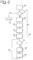
- Figure 2 is a flow-chart, exemplary of the Bit Swap arrangement described herein;
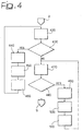
- Figure 3 shows a first portion of a sub-routine included in the arrangement described herein, and
- Figure 4 shows a second portion of the sub-routine of figure 3.
- Figure 1 shows a typical context of ADSL use.
- At present ADSL (an acronym for Asymmetric Digital Subscriber Lines) is by far the most extensively used broadband Internet delivery method.
- As schematically shown in figure 1, ADSL allows nominally 1.5 Mbps (in a range typically 500 kbps to 12 Mbps) to be delivered to customers on telephone lines downstream and roughly about 1/3 to 1/10 that rate to be delivered from the customer to the telephone operator upstream (where it is sent to the Internet service provider).
- In the block diagram of figure 1 a large area network such as the Internet is designated N, while L designates as a whole a subscriber line enabling a user U (typically, a home user) to connect to the network N via a terminal such as a personal computer PC.
- Equipment located with the user U includes a so-called "POTS (Plain Old Telecom Service) splitter" unit SU that preserves the possibility for the user to exploit the line(s) L for standard voice service via one or more telephone units TU. Connection of the terminal PC to the split unit SU is via an ADSL modem M. This is oftentimes configured in such a way to permit the user to connect to the network N to obtain additional services such as audio/video streaming services to be possibly displayed over an audio/video terminal TV. Additional features may offer the user a voice-over-IP service via a telephone terminal IPT equipped for IP voice communications.
- The equipment at the telecommunication operator exchange EX includes another split unit US and a respective plurality of modems TM1, TM2, ..., TMN, each adapted to serve a respective user.
- The modems TM1, ..., TMN are connected to the network N via a so-called ADSL access Mux (DSLAM) that is usually connected also to a video switch VS. Interposed between the split unit US and the DSLAM is a further ISDN switch again currently designated POTS.
- All the foregoing corresponds to basic principles and criteria of operation that are well known in the art. Additionally, in the following it will be generally assumed that the reader is familiar with the general structure and operation of an ADSL modem as used on the user side as disclosed e.g. in ITU G.992.1 (G.DMT): Asymmetrical digital subscriber line (ADSL) transceivers, 07/1999), thus making it unnecessary to provide a more detail description herein.
- As indicated in the foregoing, a so-called Bit Swap arrangement is used during ShowTime (that is during the session involving transmission of the data payload) in order to improve the quality of modem performance.
- The arrangement described herein operates at the receiver side, namely within the modem designated M in Figure 1. There, the arrangement is in a position to monitor the Signal-to-Noise Ratio and has all the information available as needed to take a Bit Swap decision, that is moving bits between different tones or change the tone gains in the modem. The main target of the Bit Swap arrangement is to minimize the bit error rate or, equivalently, to maximize the noise margin, especially in the case of VDSL modems. At present VDSL (an acronym for Very High Speed Digital Subscriber Lines) is a most promising modem arrangement able to support high data rates (up to 100Mbps).
- An interesting point in the Bit Swap arrangement described herein is the derivation of an array of the maximum gain increase "gmax_step" parameters (designated 100 in Fig. 2 - one parameter is needed for each tone used), that is the ratio (difference in dB) between the maximum gain (once all the constrains are fixed), that a certain tone e.g. in an ADSL modem can reach, and the current gain g(i) in the tone with index i.
- In a VDSL modem this parameter definition consists mainly in the derivation of the limitation of the power spectral density (PSD) in sliding bandwidth windows. The sliding window parameter derivation can be performed even outside before the "Main Bit Swap" function because usually it does not require the knowledge of the SNR(i) but just the power constrain mathematical description.
- The arrangement described herein is based on the assumption that the best place to derive this parameter is within the "Main Bit Swap" function for numerical stability reasons.
- This function will be explained in detail the following.
- The maximum gain depends on the power constrains, but also on the dynamics constrains of the current gain gi (for example ±2.5 dB). In addition, the resolution of the gain (g (i) in tone with index i) variation (for example step of 1dB, this is a typical protocol limitation) is considered in this calculation.
- All the corresponding computations are based on the SNR measure and more then one Bit Swap requests can be derived using the same SNR request. This way of operating reduces the computational complexity because several parameters are based on the margin and do not require to be recalculated but simply updated and this only for tones that have changed.
- The most important advantages of the proposed arrangement are:
- low complexity: this makes it possible to manage a high number of tones (more then 2k in VDSL);
- the arrangement converges very close to the optimum solution;
- priority: the main target is to increase as fast as possible the Multi-Tone margin. Then the arrangement tries to optimize also the situation for low-priority tones;
- instability and block values for b(i)/g(i) (current bit/ current gain in tone with index i) distributions are avoided. The related parameters are chosen with a very conservative criterion.
- A main assumption is the linearity of the SNR(i) in respect of the current gain g(i) (it means that inter-symbol interference and inter-carrier interference should be not dominant).
- As stated in the standard ANSI, "T1E1.4 VDSL Draft Trial-Use Standard:
Part 3", each Bit Swap Request is composed of four message fields, each one with a single command. In each Bit Swap Request, it is possible to insert a number smaller than four commands, inserting the command 'Do nothing'. - More than four commands are not generally allowed. Conversely, the possibility exists of:
- increasing/decreasing by one the number of bits allocated (without changing the total number of bit allocated);
- changing the transmitted power by the factor of, for example, -2, -1, +1, +2 and +3 dB.
- In any case, the Bit Swap Request has to perform power adjustment with the following power requirements:
- a gain adjustment with a maximum range -2.5 dB +2.5 dB on the transmitted PSD is allowed;
- the PSD template defines power limitation measured with the resolution bandwidth of 100kHz in the in-band frequency range below 1.0MHz and with the resolution bandwidth of 1MHz in the in-band frequency range above 1.0MHz (using a 100KHz and 1MHz sliding window, respectively). This is a constraint that is very difficult to manage as it links each tone to many other groups of tones (usually called windows because bases on a fix number of consecutive tones). This constrain is directly translated in an upper limitation of the power in different sliding window over all used tones. This limitation is used in VDSL standard to avoid cross-talk increase in a specific bandwidth but not inserted in ADSL standard.
- The sliding window power constraint has a high impact on the Bit Swap arrangement complexity and it is even worse in case of variable sliding window length. For that reason, a submultiple sliding window length (for example 100kHz-sliding window instead of 1MHz-sliding window) for all the frequencies is proposed. Such choice is standard compliant. This means that the power for each sliding window of NUMBER_OF_TONES_PSD_AVERAGE tones equal to a given number of tones is derived.
- The complexity of a Bit Swap arrangement is proportional to the sliding window length, NUMBER_OF_TONES_PSD_AVERAGE. For example, the power increase of one tone can potentially influence (two times NUMBER_OF_TONES_PSD_AVERAGE - 1) tones because the number of tones that belong to all possible sliding window containing a certain tone is (two times NUMBER_OF_TONES_PSD_AVERAGE - 1).
- The main function that implement the Bit Swap arrangement is the "Constrain Parameter Derivation" function.
- The SNR measurement (Fig. 2, 130.) array is then processed and it is derived the per-tone noise margin array. The per-tone noise margin array is the main input of a Bit-Swap arrangement. The minimum SNR to obtain a BER=10-7 as a function of the constellation size is referred to as SNR (b (i)) .
- The main input of this function is the per tone margin set; for a certain tone i with b(i) bits, the equation below gives a Check Bit Swap parameter:

- The main function that implements the Bit Swap arrangement is the "Main Bit Swap" function (its flow-chart is shown in Fig. 2). This function is in charge of deciding if a Bit Swap Request is to be performed, by calling (Fig. 2, 190) the "Independent Bit Swap" function (in which a single set of command is decided, flow-chart in Figs. 3 an 4) and, if affirmative, how many Bit Swap Requests have to be processed, on a single SNR measurement. The number of Bit Swap Requests is updated (Fig.2, 200) must be lower than a fixed constant ("MAX_NBR_MSG", Fig. 2, 170), and each new Bit Swap Request is conditioned on having a previous Bit Swap Request not idle (Fig. 2, 110). The derivation of more than one Bit Swap Request per SNR measurement helps in reducing the average time needed to apply a Bit Swap command and to reduce the complexity of the algorithm. This may lead to an increased average time of reaction to noise variation.
- In the "Main Bit Swap" function, a Local Target Margin, i.e. a feasible margin to be reached with a certain number of Bit Swap Requests, is computed (Fig. 2, 140).
- i. estimation of a Local Target Margin. Two methods are proposed here;
- ii. estimation of margin improvement with one additional bit on each tone, maximum obtainable margin on each tone; decision on enabling only Power Decrease; derivation of Hysteresis parameters when more than one Bit Swap Requests have to be carried out on the same SNR measurement;
- iii. cyclic call of the "Independent Bit Swap" function; each function call gives as an output a Bit Swap Request (i.e. a coherent list of commands).
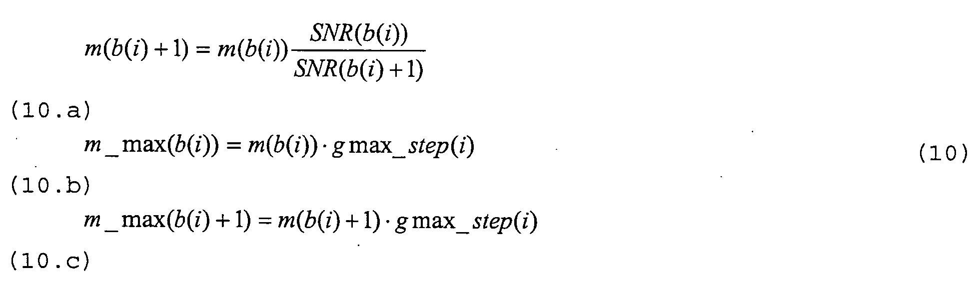
- Additionally other important parameters are derived (Fig. 2, 160). Equations (10) provides an exact definition of such parameters. They are:
- The per-tone margin (m(b(i)+1)) supporting the current number of bits plus one defined in equation 10.a.
- The maximum margin we can reach on the current number of bits (m_max(b(i))) defined in equation 10.b.
- The maximum margin we can reach on the current number of bits plus one (m_max (b(i)+l)) defined in equation 10.c.
- The output of the "Main Bit Swap" function is a list of VOC (VDSL Overhead channel) Bit Swap Requests (Fig. 2, 120). If no Bit Swap Request has to be issued, the Bit Swap Request must be avoided. Otherwise, the protocol starts as described in ANSI, "T1E1.4 VDSL Draft Trial-Use Standard:
Part 3". - The heart of the Bit Swap arrangement described herein is the "Independent Bit Swap" function (described in Fig. 3 and 4, header in 300) that is in charge of two operations: it decides which Bit Swap commands have to be made and it segments the VOC message. The VOC message segmentation can be done in a sub-routine without any loss of generality. The main output of this function is a list of coherent Bit Swap commands of a VOC message.
- The main complexity (or a big part of it) of the arrangement is assumed to be due to the Constrain Parameters Derivation function (mainly Sliding Window parameter derivation in VDSL) that computes power constrains limitations. For that reason, the choice has been made of splitting this derivation in two functions: Power Constrains Derivation and Power Constrains Update.
- The first function is run after the values for the current gain g(i) are definitively derived, i.e. after the BiGi Compression algorithm during the Channel Analysis & Exchange state or "Main Bit Swap" function (Fig. 2, 100) if numerical stability problems are foreseen. This function derives the power constrains limitations on all the transmission bandwidth in a very efficient way (the high number of tones and the possibility of different bands is to be taken into account).
- The second function must be called by the "Independent Bit Swap" function if a variation of gain is done. In that case, a variation of the power constrain should indeed be derived locally: a variation of one gain has impact on no more than (twice NUMBER_OF_TONES_PSD_AVERAGE-1) tones. Using a specific function, this operation can be carried out in a very efficient way.
- The second function will be explained in detail the following in VDSL sliding window constrain (Fig. 3, 410).
- The Independent Bit Swap Function is the more important function related to Bit Swap: it takes the Bit Swap decision and segments the VOC messages. It is composed of three main steps:
- i. in the first step a Bit Swap (BS) decision is taken.
A priority order is considered here:- a. urgent BS, where the decision functional is the margin (Fig. 3, 350).
- b. not urgent BS, where the decision functional is the maximum margin (see the Equations designated 10.a and 10.b above - Fig. 3, 360) ;
- ii. in the second step, a Power Increase (PI) decision is taken (Fig. 4, 440, 450, 460);
- iii. in the third step, a Power Decrease (PD) decision is taken (Fig. 4, 490, 500, 510).
A priority order is considered here:- a. active tones (no pilot, and b(i)>0) with g (i) ≥1;
- b. active tones (no pilot, and b(i)>0) with a gain that can be decreased;
- c. idle tone (no pilot, b(i)=0) with a gain that can be decreased.
- The previous list gives also a decreasing priority order of different commands (i.e. BS has a higher priority than PD). An iteration that includes steps i, ii and iii is inserted. This means that all steps are evaluated and, at the end, if at least one command is available and at least one command was used, a new iteration is performed.
- This approach helps in increasing the efficiency of the arrangement (i.e. to use, if possible, all the available commands)
- Three types of tones will be considered:
- Active Tone;
- Pilot Tone;
- Idle Tone (i.e. with bi=0).
- The first step can run only if a minimum number of commands are available. For an urgent BS (i.a), at least two commands are required while for a non-urgent BS (i.b) two commands plus half of the used commands (to be used for a potential PI) are required. This is because the BS command pair does not guarantee by itself a margin improvement, while a BS command pair in conjunction with one PI guarantees it.
- The decision on the tones on which the Urgent Bit Swap should be performed is based on the margin parameter mi (bi). If one tone has a margin with one additional bit higher than a current tone margin the bit swap is done.
- The candidate tone to lose one bit is the active or pilot tone with minimum m(b(i)) while the candidate tone to obtain one additional bit is the active or idle tone with higher m(b(j)+1).
- The decision on the tone on which the Non Urgent Bit Swap (i.b) should be performed is based on the parameter m_max (b(i)). This is defined as the maximum margin that can be reached with one PI operation. The decision of a PI action is independently taken in step ii. See Equation 10 for the exact definition.
- The candidate tone to lose one bit is the active or pilot tone with minimum m_max(b(i)) while the candidate tone to obtain one additional bit is the active or idle tone with higher m_max(b(j) +1) .
- In both methods, the BS operation between tones i and j is done if the ratio between the reference margin m(b(i)) and the maximum margin m_max(b (i)) respectively for Urgent Bit Swap and Not Urgent Bit Swap is higher than SWAP_DELTA_MARGIN. SWAP_DELTA_MARGIN parameter is used to guarantee reliable operation.
- The SWAP_DELTA_MARGIN is the minimum parameter between max (m (b (i) ) ) /min (m (b (j) +1) ) and max ( m(b(i)))/min(m_max(b (j)+ 1) ) for Urgent BS and Not Urgent BS to perform a bit swap operation, respectively.
- Having SWAP_DELTA_MARGIN>1 ensure a stable operation.
- Once the decision is taken to perform the BS operation, the following actions have to be taken:
- increase/decrease the swapped bits;
- update the margin m(b(i)) and m(b(i)+1), maximum margin m_max(b(i)) and m_max (b(i)+1) for both tones with index i and j;
- build Bit Swap Request message.
- The second step is related to the Power Increase operation. Given the "increasable" gain array, gmax_step(i), and the margin array m(b(i)), the candidate tone for PI is chosen as the active tone with an "increasable" gain (i.e. with gmax_step(i)>1) and with a minimum margin m(b(i)).
- The PI operation is performed if:
- the minimum margin is lower then the local target margin, ΓMC;
- at least one command can be used in this operation.
- In this case, the main operations to be carried out are:
- derivation of the new g(i) (gnew);
- update the margin m(b(i)) and m(b(i)+1), maximum margin m_max(b(i)) and m_max(b(i)+1) only for tone i;
- update the power constraint(s);
- build the Bit Swap Request message.
- The third step is related to the PD command. Given the increasable gain array, gmax_step(i), and the margin array m(b(i)), and a mask identifying to which of the three sets the tones belong, the tone with the maximum margin is found for every set. Three consecutive iterations are performed, each based on a different set of tones. The candidate tone chosen for PD is the one with the maximum margin among these three sets of tones. Different priorities are considered as already explained in iii.a, iii.b and iii.c. The main difference between the different priorities is the set in which the tone candidate to the power reduction is found.
- In all cases considered, the PD operation is performed if:
- the margin on the tone is higher than the local target margin ΓMC increased by GI_INC_STEP and the safety parameter MAXIMUM_ADDITIONAL_MARGIN (added to avoid instability); and
- at least one command is available for this operation.
- If the PI operation is carried out, the main operations performed are:
- Derivation of the new g(i);
- Update the margin m(b(i)) and m(b(i)+1), maximum margin m_max (b (i) ) and m_max (b (i) +1) for tone i;
- Update power constrains;
- Built Bit Swap Request message.
- A practical embodiment of the arrangement described in the foregoing will now be described in connection with the flowcharts of figures 2 to 4.
- In Figure 2,
reference numeral 100 indicates an input step which performs a per tone derivation of the maximum increase of gain based on all power, PSD, sliding window, protocol constrains (this operation is usually called constrain parameter update). After that, in a decision step 110 a decision is taken as to whether a Bit Swap strategy is to be continued or stopped. If the decision is to stop the Bit Swap algorithm, the next step is astep 120 that causes the exit from the Bit Swap algorithm and provide a list of Bit Swap requests. - Conversely, if the decision is to continue the Bit Swap algorithm, the successive step is a
step 130. Thisstep 130 performs a per tone SNR measurement. Insuccessive step 140 the difference between the measured SNR and the SNR_required(b) is calculated and the result is assigned to a margin parameter m(b(i)). This operation is executed for values of b between (b(i) - 1) and (b (i) + 1). Anext step 150 performs the operation for calculating the local target margin that is a reachable Muti-Tone Margin. After that astep 160 calculates the maximum margin m_max:(i) = (m(b(i)) + Gmax_step) for value of b included between (b(i)) and (b(i)+1), and N_msg variable is forced to zero. - The
successive step 170 is another decision step. If the condition N_msg < MAXN_MSG is verified, the next step is astep 190, otherwise theline 180 indicates that the algorithm returns to thedecision step 110. Thestep 190 is a function-call step and recalls the INDBITSWAP sub-routine described in Figure 3 and Figure 4. Thelast step 200 performs the unit increment of the parameter N_msg. Theline 210 indicates that after thestep 200 the algorithm returns to thedecision step 170. - Specifically, in Figure 3 the
step 300 indicates the start step of the INDBITSWAP sub-routine and this step is referred to as 190 in Figure 1. - The
step 310 in Figure 3 is an initialization step. In thisstep 310 the value one is assigned to Do_something parameter, and the value zero is assigned to Msg_length parameter. The first one is a Boolean parameter while the second is an integer. After that, in adecision step 320 the Boolean condition ((Msg_length < MAX_MSG_LENGTH) & (Do_something)) is evaluated. If the condition is false, the successive step is astep 520, which causes the exit from the algorithm delivering the list of commands. Otherwise if the condition is true, the next step is anotherinitialization step 330 that assigns zero to Do_something Boolean parameter and one to Type_bs parameter. Therefore the next step is aselection step 340 that chooses a different way of operating on the basis of the value of Type_bs parameter. If Type_bs parameter is equal to one, the process continues with thestep 350. In thisstep 350 the minimum margin value (m(b(i))) is assigned to the parameter (Mmin imin), and the maximum margin value (m(b(i) + 1)) is assigned to the parameter (Mmax imax), where M represents the max/min value and i is the related index. If the Type_bs parameter is equal to two the algorithm continues with astep 360. In thisstep 360 the minimum margin value (m_max(b(i))) is assigned to the parameter (Mmin imin), and the maximum margin value (m_max(b(i) + 1)) is assigned to the parameter (Mmax imax) . The next step for each of the previous ways is thedecision step 370 where the Boolean condition ((Msg_length < MAX_MSG_LENGTH - 1) & (Mmax/Mmin > const1)) is evaluated. The const1 is a BS hysteresis parameter. - If the condition is false the following step is a
step 380 where the value of Type_bs is incremented by one unit, and the algorithm returns toselection step 340. Otherwise, if the condition instep 370 is true, the successive step is astep 390 where a bit swap tone between tone with index imin and imax takes place, and then the value of Msg_length is incremented by two units, and finally Do_something is set equal to one. After that, in astep 400 the value of b (imin) is decremented by one unit and the value of b (imax) is incremented, by one unit. In asubsequent step 410 Gmax_step array, m(b) and m_max(b) are updated for all the tones involved for values of b between [b(i) (b(i)+1)]. Afterstep 410, the algorithm return to theselection step 340. If the value of Type_bs is equal to three afterstep 340step 420 in Figure 4 is executed. - In the
step 420 the minimum margin value (m(b(i))) is assigned to the parameter (Mmin imin) of all gain increasable tones. Thesubsequent step 430 is a decision step where the Boolean condition ((Msg_length < MAX_MSG_LENGTH - 1) & (Mmin < Target_margin_local * const2)) is evaluated. The const2 is a PI (power increase) hysteresis parameter. If thecondition 430 is verified the algorithm continues with astep 440 where a gain increase is derived for tone imin and parameter Msg_length is incremented by one unit, and finally Do_something is set equal to one. - A
subsequent step 450 produces an update operation in the current gain g(imin). In asubsequent step 460 the update operations of Gmax_stepi, m(b(i)) and m_max(b(i)) for all the tones involved are performed for values of b between [b (i) (b (i) +1) ] . Afterstep 460, the algorithm returns to thestep 420. - On the other side, if the
condition 430 is false, the process continues with astep 470 where the minimum margin value (m(b(i))) is assigned to the parameter (Mmin imin) for all the gain decreasable tones. Thesuccessive step 480 is a decision step where the Boolean condition ((Msg_length < MAX_MSG_LENGTH - 1) & (Mmin < Target_margin_local * const3)) is evaluated. The const3 is a PD (power decrease) hysteresis parameter. If thecondition 480 is verified, the process continues with astep 490. In the step 490 a gain decrease is derived for tone imax and the parameter Msg_length is incremented by one unit, and finally Do_something is set equal to one. - The
subsequent step 500 involves an update operation of the current gain g(imax). In thesuccessive step 510 the update operations of Gmax_step array, m(b) and m_max (b) are performed for all the tones involved for values of b between [b(i) (b(i)+1)]. After that, the algorithm returns to thestep 470. - Of course, without prejudice to the underlying principle of the invention, the details and embodiments may vary, also significantly, with respect to what has been described and shown, just by way of example, without departing from the scope of the invention as defined by the claims that follow.
Claims (21)
- A method for controlling performance of a modem arrangement (M) wherein a plurality of tones having associated gains with respective maximum reachable values (gmaxi) are used for carrying respective bitstreams, the method including at least one of selectively swapping bits between said tones in said plurality and selectively changing said tone gains to optimize an error parameter (BER, NM), the method including the steps of:- determining the current values (gi) for said associated gains,- determining the gain margins between said maximum reachable values (gmaxi) and said current values (gi), and- performing, to optimize said at least one error parameter as a function of said gain margins, at least one of:- varying the number of bits allocated to said tones, and- performing a transmitted power variation by varying said gains (gi, gnew) .
- The method of claim 1, including the step of increasing/decreasing the number of bits associated to each said tones without changing the total number of bits allocated thereto.
- The method of either of claims 1 or 2, characterized in that said transmit power variation includes either increasing or decreasing said gains.
- The method of claim 1, characterized in that it includes the step of varying said gains by discrete steps.
- The method of claim 1, characterized in that it includes the step of determining said gain margins as a difference in dB between said maximum reachable gain values (gmaxi) and said current gains (gi).
- The method of any of the previous claims, characterized in that it includes the step of selecting said error parameter as a bit error rate (BER) whereby said step of optimizing involves minimizing said bit error rate as a function of said gain margins.
- The method of any of the previous claims, characterized in that it includes the step of selecting said error parameter as a noise margin (NM), whereby said step of optimizing involves maximizing said noise margin (NM) as a function of said gain margins.
- The method of claim 1, characterized in that said step of varying said gains involves a power decrease and in that said power decrease is effected on said tones of said plurality based on a priority order including:- active tones having a current value (gi) for said associated gain larger or equal to one;- active tones having a current value (gi) for said associated gain that can be decreased, and- idle tones having a current value (gi) for said associated gain that can be decreased.
- The method of claim 1, characterized in that it includes the step of giving to said operation of varying the number of bits allocated to said tones priority over said transmitted power variation, at least in so far as said transmit power variation involves a power decrease.
- The method of claim 1, characterized in that said steps of varying the number of bits allocated to said tones, includes the step of selecting:- a candidate tone to lose one bit as a tone having a minimum value for said margin (mi(bi); mmax,i (bi)), and- selecting a candidate tone to obtain one additional bit as a tone having a higher value for said margin (mj (bj+1) ,mmax,j (bj+1)).
- The method of claim 1, characterized in that it includes the step of identifying, among said tones of said plurality, tones on which said bit swapping as to performed urgently based on an urgency margin parameter (mi(bi)) indicative of respective tone having a margin with one additional bit higher than the current value for said margin.
- The method of claim 1, characterized in that it includes the step of selecting among said tone of said plurality tones for which said bit swapping is to performed on a non-urgent bases as a function of a non-urgency maximum margin indicative of the maximum margin that can be reached in said tone by means of a transmitter power increase (PI).
- The method of either of claim 11 and claim 12, characterized in that it includes the step of comparing either of said urgency margin or non-urgency margin with at least one threshold value (SWAP DELTA MARGIN) .
- A system for controlling performance of modem arrangement, wherein the system is configured for performing the steps of any of claims 1 to 13.
- The system of claim 14, characterized in that said plurality of tones comprise a discrete multi-tone-technology (DMT) arrangement.
- The system of claim 14, characterized in that said plurality of tones comprise an Orthogonal Frequency Division Multiplexing (OFDM) arrangement.
- The system of claim 14, characterized in that said modem is a DSL modem.
- The system of claim 17, characterized in that said modem is a VDSL modem.
- The system of claim 18, characterized in that said modem is an ADSL modem.
- The system of any of claims 15 to 19, characterized in that said modem arrangement has an associated feedback channel.
- And comprising software code portions for performing the steps of any of claims 1 to 15 when the product is run on the computer.
Priority Applications (2)
| Application Number | Priority Date | Filing Date | Title |
|---|---|---|---|
| EP04029272A EP1670201A1 (en) | 2004-12-10 | 2004-12-10 | Bit Swap algorithm to improve modem performance |
| US11/496,970 US7664169B2 (en) | 2004-12-10 | 2006-07-31 | Method and system for improving modem performance, computer program product therefor |
Applications Claiming Priority (1)
| Application Number | Priority Date | Filing Date | Title |
|---|---|---|---|
| EP04029272A EP1670201A1 (en) | 2004-12-10 | 2004-12-10 | Bit Swap algorithm to improve modem performance |
Publications (1)
| Publication Number | Publication Date |
|---|---|
| EP1670201A1 true EP1670201A1 (en) | 2006-06-14 |
Family
ID=34927721
Family Applications (1)
| Application Number | Title | Priority Date | Filing Date |
|---|---|---|---|
| EP04029272A Withdrawn EP1670201A1 (en) | 2004-12-10 | 2004-12-10 | Bit Swap algorithm to improve modem performance |
Country Status (2)
| Country | Link |
|---|---|
| US (1) | US7664169B2 (en) |
| EP (1) | EP1670201A1 (en) |
Families Citing this family (3)
| Publication number | Priority date | Publication date | Assignee | Title |
|---|---|---|---|---|
| US20070195871A1 (en) * | 2006-02-22 | 2007-08-23 | Texas Instruments Incorporated | Performance of DSL modem under impulse noise |
| US8586398B2 (en) * | 2008-01-18 | 2013-11-19 | Miasole | Sodium-incorporation in solar cell substrates and contacts |
| US8285068B2 (en) * | 2008-06-25 | 2012-10-09 | Cisco Technology, Inc. | Combined deblocking and denoising filter |
Citations (4)
| Publication number | Priority date | Publication date | Assignee | Title |
|---|---|---|---|---|
| EP0918422A2 (en) * | 1997-11-24 | 1999-05-26 | Motorola, Inc. | Method for reallocating data in a discrete multi-tone communication system |
| WO2002017584A2 (en) * | 2000-08-24 | 2002-02-28 | Centillium Communications, Inc. | Bit swapping and dynamic rate adjustment for multicarrier transmission in a digital subscriber line system |
| WO2002060145A2 (en) * | 2001-01-25 | 2002-08-01 | Bandspeed, Inc. | Method for adaptive bit assignment and fine gain setting in a multi-carrier communications system |
| US20020163973A1 (en) * | 2001-05-07 | 2002-11-07 | Shang-Ho Tsai | Method and apparatus for selecting an optimal swapping technique in discrete multi-tone system |
Family Cites Families (2)
| Publication number | Priority date | Publication date | Assignee | Title |
|---|---|---|---|---|
| US5479447A (en) * | 1993-05-03 | 1995-12-26 | The Board Of Trustees Of The Leland Stanford, Junior University | Method and apparatus for adaptive, variable bandwidth, high-speed data transmission of a multicarrier signal over digital subscriber lines |
| US6829307B1 (en) * | 1999-02-24 | 2004-12-07 | The Board Of Trustees Of Leland Stanford Junior University | Express bit swapping in a multicarrier transmission system |
-
2004
- 2004-12-10 EP EP04029272A patent/EP1670201A1/en not_active Withdrawn
-
2006
- 2006-07-31 US US11/496,970 patent/US7664169B2/en not_active Expired - Fee Related
Patent Citations (4)
| Publication number | Priority date | Publication date | Assignee | Title |
|---|---|---|---|---|
| EP0918422A2 (en) * | 1997-11-24 | 1999-05-26 | Motorola, Inc. | Method for reallocating data in a discrete multi-tone communication system |
| WO2002017584A2 (en) * | 2000-08-24 | 2002-02-28 | Centillium Communications, Inc. | Bit swapping and dynamic rate adjustment for multicarrier transmission in a digital subscriber line system |
| WO2002060145A2 (en) * | 2001-01-25 | 2002-08-01 | Bandspeed, Inc. | Method for adaptive bit assignment and fine gain setting in a multi-carrier communications system |
| US20020163973A1 (en) * | 2001-05-07 | 2002-11-07 | Shang-Ho Tsai | Method and apparatus for selecting an optimal swapping technique in discrete multi-tone system |
Non-Patent Citations (1)
| Title |
|---|
| SHANG-HO TSAI ET AL: "Combined bit swap and power gain adaptation for error rate equalization in dmt systems", ACOUSTICS, SPEECH, AND SIGNAL PROCESSING, 2004. PROCEEDINGS. (ICASSP '04). IEEE INTERNATIONAL CONFERENCE ON MONTREAL, QUEBEC, CANADA 17-21 MAY 2004, PISCATAWAY, NJ, USA,IEEE, vol. 4, 17 May 2004 (2004-05-17), pages 1065 - 1068, XP010718773, ISBN: 0-7803-8484-9 * |
Also Published As
| Publication number | Publication date |
|---|---|
| US20070140325A1 (en) | 2007-06-21 |
| US7664169B2 (en) | 2010-02-16 |
Similar Documents
| Publication | Publication Date | Title |
|---|---|---|
| US6222888B1 (en) | Method and circuit for controlling setup of multichannel system | |
| EP1863249B1 (en) | Method and device for dynamic spectrum management of xDSL upstream and downstream shared frequency | |
| US8009692B2 (en) | Bit and power allocation scheme for full-duplex transmission with echo cancellation in multicarrier-based modems | |
| US6075821A (en) | Method of configuring and dynamically adapting data and energy parameters in a multi-channel communications system | |
| EP1894377B1 (en) | Dsl system loading and ordering | |
| Papandreou et al. | A new computationally efficient discrete bit-loading algorithm for DMT applications | |
| US7974583B2 (en) | Real-time formation of optimal power spectral density masks | |
| CN101610102B (en) | Method, system and device for optimizing power | |
| US6128348A (en) | Method for configuring data and energy parameters in a multi-channel communications system | |
| US7295621B2 (en) | Communication start-up with variant spectral density mask | |
| US6628754B1 (en) | Method for rapid noise reduction from an asymmetric digital subscriber line modem | |
| JP2003258751A (en) | Application-driven adaptive duplex method and apparatus for digital subscriber loop | |
| US8243844B2 (en) | Power reduction for digital subscriber line | |
| US6732281B1 (en) | System and method for loading data onto carriers | |
| US6732323B1 (en) | Method of selecting initialization parameters for multi-channel data communication with forward error correction | |
| US20080220725A1 (en) | Data transmission method, communication system, transceiver, transmitter and receiver | |
| US7664169B2 (en) | Method and system for improving modem performance, computer program product therefor | |
| US7536197B2 (en) | Apparatus and method of loop and rate dependent power cutback | |
| US20020061059A1 (en) | Scheme for the initialization of ADSL modems | |
| EP2348644B1 (en) | Upstream power back-off method in digital subscriber line and the device and the system thereof | |
| CN116418918B (en) | Systems for optimizing achievable rates and methods suitable for digital subscriber line communication systems | |
| US6856683B1 (en) | Method for reducing noise from a non-linear device that shares a customer loop with an asymmetric digital subscriber line modem | |
| JP3685756B2 (en) | Method for transmitting transmission data using a subscriber modem | |
| US7333535B2 (en) | Variable block rate ADSL | |
| Jakovljević et al. | VDSL power back-off parameter optimization for a cable bundle |
Legal Events
| Date | Code | Title | Description |
|---|---|---|---|
| PUAI | Public reference made under article 153(3) epc to a published international application that has entered the european phase |
Free format text: ORIGINAL CODE: 0009012 |
|
| AK | Designated contracting states |
Kind code of ref document: A1 Designated state(s): AT BE BG CH CY CZ DE DK EE ES FI FR GB GR HU IE IS IT LI LT LU MC NL PL PT RO SE SI SK TR |
|
| AX | Request for extension of the european patent |
Extension state: AL BA HR LV MK YU |
|
| AKX | Designation fees paid | ||
| REG | Reference to a national code |
Ref country code: DE Ref legal event code: 8566 |
|
| STAA | Information on the status of an ep patent application or granted ep patent |
Free format text: STATUS: THE APPLICATION IS DEEMED TO BE WITHDRAWN |
|
| 18D | Application deemed to be withdrawn |
Effective date: 20061215 |