EP1670194B1 - Service guarantee and congestion control in high speed networks - Google Patents
Service guarantee and congestion control in high speed networks Download PDFInfo
- Publication number
- EP1670194B1 EP1670194B1 EP06111782A EP06111782A EP1670194B1 EP 1670194 B1 EP1670194 B1 EP 1670194B1 EP 06111782 A EP06111782 A EP 06111782A EP 06111782 A EP06111782 A EP 06111782A EP 1670194 B1 EP1670194 B1 EP 1670194B1
- Authority
- EP
- European Patent Office
- Prior art keywords
- channel
- resource
- data
- data element
- queue
- Prior art date
- Legal status (The legal status is an assumption and is not a legal conclusion. Google has not performed a legal analysis and makes no representation as to the accuracy of the status listed.)
- Expired - Lifetime
Links
Images


Classifications
-
- H—ELECTRICITY
- H04—ELECTRIC COMMUNICATION TECHNIQUE
- H04L—TRANSMISSION OF DIGITAL INFORMATION, e.g. TELEGRAPHIC COMMUNICATION
- H04L12/00—Data switching networks
- H04L12/54—Store-and-forward switching systems
- H04L12/56—Packet switching systems
- H04L12/5601—Transfer mode dependent, e.g. ATM
- H04L12/5602—Bandwidth control in ATM Networks, e.g. leaky bucket
-
- H—ELECTRICITY
- H04—ELECTRIC COMMUNICATION TECHNIQUE
- H04L—TRANSMISSION OF DIGITAL INFORMATION, e.g. TELEGRAPHIC COMMUNICATION
- H04L12/00—Data switching networks
- H04L12/66—Arrangements for connecting between networks having differing types of switching systems, e.g. gateways
-
- H—ELECTRICITY
- H04—ELECTRIC COMMUNICATION TECHNIQUE
- H04L—TRANSMISSION OF DIGITAL INFORMATION, e.g. TELEGRAPHIC COMMUNICATION
- H04L47/00—Traffic control in data switching networks
- H04L47/10—Flow control; Congestion control
-
- H—ELECTRICITY
- H04—ELECTRIC COMMUNICATION TECHNIQUE
- H04L—TRANSMISSION OF DIGITAL INFORMATION, e.g. TELEGRAPHIC COMMUNICATION
- H04L47/00—Traffic control in data switching networks
- H04L47/10—Flow control; Congestion control
- H04L47/12—Avoiding congestion; Recovering from congestion
-
- H—ELECTRICITY
- H04—ELECTRIC COMMUNICATION TECHNIQUE
- H04L—TRANSMISSION OF DIGITAL INFORMATION, e.g. TELEGRAPHIC COMMUNICATION
- H04L47/00—Traffic control in data switching networks
- H04L47/10—Flow control; Congestion control
- H04L47/16—Flow control; Congestion control in connection oriented networks, e.g. frame relay
-
- H—ELECTRICITY
- H04—ELECTRIC COMMUNICATION TECHNIQUE
- H04L—TRANSMISSION OF DIGITAL INFORMATION, e.g. TELEGRAPHIC COMMUNICATION
- H04L47/00—Traffic control in data switching networks
- H04L47/10—Flow control; Congestion control
- H04L47/29—Flow control; Congestion control using a combination of thresholds
-
- H—ELECTRICITY
- H04—ELECTRIC COMMUNICATION TECHNIQUE
- H04L—TRANSMISSION OF DIGITAL INFORMATION, e.g. TELEGRAPHIC COMMUNICATION
- H04L47/00—Traffic control in data switching networks
- H04L47/10—Flow control; Congestion control
- H04L47/30—Flow control; Congestion control in combination with information about buffer occupancy at either end or at transit nodes
-
- H—ELECTRICITY
- H04—ELECTRIC COMMUNICATION TECHNIQUE
- H04L—TRANSMISSION OF DIGITAL INFORMATION, e.g. TELEGRAPHIC COMMUNICATION
- H04L47/00—Traffic control in data switching networks
- H04L47/10—Flow control; Congestion control
- H04L47/32—Flow control; Congestion control by discarding or delaying data units, e.g. packets or frames
-
- H—ELECTRICITY
- H04—ELECTRIC COMMUNICATION TECHNIQUE
- H04L—TRANSMISSION OF DIGITAL INFORMATION, e.g. TELEGRAPHIC COMMUNICATION
- H04L12/00—Data switching networks
- H04L12/54—Store-and-forward switching systems
- H04L12/56—Packet switching systems
- H04L12/5601—Transfer mode dependent, e.g. ATM
- H04L2012/5629—Admission control
- H04L2012/5631—Resource management and allocation
- H04L2012/5636—Monitoring or policing, e.g. compliance with allocated rate, corrective actions
Definitions
- This invention relates to congestion controls for use in data networks.
- Data networks switch elements of data (data elements) such as packets or cells.
- data elements data elements
- Each channel shares resources of the network, a resource being, for example, a queue and an associated server.
- a minimum bandwidth is assigned to each channel in the network according to a contract between the network provider and an entity to which the channel is assigned.
- An entity may be a group of data element sources or it may be a single data element source.
- An association exists between each data element and a channel assigned to its source. The association may be established before, or as, the data element enters the data network.
- Prior data networks as disclosed in, for example, EP 0 487 235 , of the type in which a minimum bandwidth is contracted for by each channel have suffered from a variety of problems in their allocation of bandwidth to the active channels at a resource, i.e., those channels at the resource that are carrying data elements at a particular time.
- One such problem is the so-called fairness problem, i.e., how to fairly share any available excess bandwidth among the active channels.
- Another problem relates to insuring that the active channels are allowed to actually make use of all of the bandwidth for which they have contracted. This problem arises because it is possible that an end-to-end protocol being employed over a channel may interact with the congestion control mechanisms employed by the network in such a way that a channel's contracted-for bandwidth is never actually achieved.
- Prior congestion control techniques tended, in the face of congestion, to drop data elements from all channels that exceeded their contracted-for bandwidth. This, however, could exacerbate the congestion by causing such channels to retransmit all their dropped data elements. Furthermore, such techniques for data element dropping typically result in the retransmission over a channel of more data elements than were actually dropped. Another problem with prior congestion control techniques is that many of them result in high delays for data elements in those channels that are transmitting within their contracted-for bandwidth. Lastly, errors that occur in the estimation of the actual bandwidth being used by each channel may cause a particular channel's data elements to be dropped even though such a channel is actually within its contracted-for bandwidth. This unnecessary data element dropping results in additional data element retransmissions and, potentially, additional congestion.
- a first aspect of the invention is defined in claim 1.
- a second aspect of the invention is defined in claim 3.
- FIG. 1 shows exemplary data network 100 in which the present invention is used.
- Data network 100 includes nodes 101 through 117, high speed links 118, low speed links 119, data sources 120 and access links 121.
- High speed links 118 and low speed links 119 interconnect nodes 101 through 117, in the manner shown.
- Access links 121 connect data sources 120 to various ones of the nodes of data network 100.
- Data network 100 switches data elements, e.g., either packets or cells. If data network 100 switches packets, in particular, it is called a packet switched network.
- the data elements are supplied from data sources 120. Each data element contains an indication that uniquely identifies a channel to which it is assigned.
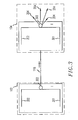
- FIG. 2 shows an expanded view of nodes 102 and 104.
- Node 102 includes access interface resource (A) 201, embodying aspects of the invention, and internal communications resources (I) 202, embodying aspects of the invention.
- Node 102 includes two of the internal communications resources (I) 202, one for each high speed link 118 terminating at node 102.
- Node 104 includes the five internal communications resources (1) 202 shown, one for each high speed link 118 terminating at node 104.
- Access interface resource (A) 201 controls communication of data elements between data network and data sources 120 over access links 121.
- Each internal communications resource (I) 202 controls the communications of data elements within data network 100 over the internal links to which it is connected, which in the case of nodes 102 and 104 are all high speed links 118. Similarly, internal communications resources (1) 202 within other nodes control the communication of data elements within data network 100 over low speed links 119.
- Access interface resource (A) 201 and internal communications resources (I) 202 can both employ the service discipline and congestion control techniques described below, pursuant to the invention.
- FIG. 3 shows transmission queues 301 and servers 302 within internal communications resource (I) 202 for a single direction of transmission.
- Data elements for transmission via high speed link 118 are queued in queue 301 prior to service and transmission by server 302.
- Server 302 can either transmit data elements out of the node, e.g., to a next node or to a data source, or route the data element to an appropriate resource within the node over links 204.
- queue 301 and server 302 are made up of a processor and its associated memory. The memory stores queued data elements while the processor manages the queue and performs the servicing functions.
- FIG. 4 is a view of a typical queue 301 and server 302 of FIG. 3 .
- data networks such as data network 100
- Queue 301 may receive data elements that were supplied by any channel of network 100.
- a minimum bandwidth is assigned to each channel in the network according to a contract between the network provider and an entity to which the channel is assigned.
- An entity may be a group of user data sources 120 or it may be a single user data source 120.
- An association exists between a data element and a channel assigned to the one of user data sources 120 that supplied the data element. The association may be established either before the data element enters the data network or in the one of access interface resources (A) 201 at which the data element is processed into data network 100. After being processed into data network 100, each data element is routed to its destination user data source 120.
- Each data element may pass through several of nodes 101 through 117 before reaching its destination.
- packets from different channels may simultaneously be waiting in queue 301 of resource for service by the associated server 302.
- the data elements of a single channel that are arriving at queue 301 may have traveled over physically diverse routes if they were supplied from different ones of user data sources 120.
- an active channel at a resource is a channel that is carrying data elements at a particular time. Therefore, a channel is an active channel at a resource if at least one data element has been received from the channel and that data element is either currently a) awaiting service in queue 301 or b) is being served by server 302.
- There are M channels defined in data network ( FIG. 1 ). Each channel is indicated by the subscript i, where i I, ..., M. Not all the channels need be active at any particular time or at any particular resource.
- the data elements of a channel active at a resource arrive that resource at the rate of ⁇ i .
- Each server 302 is capable of serving and transmitting data elements at its own predetermined maximum service rate ⁇ .
- FIG. 4 also shows global congestion threshold 403, which will be discussed further below.
- queue 301 and server 302 are logically transformed, as shown in FIG. 5 , into several smaller queues 501-1 through 501-N and corresponding servers 502-1 through 502-N.
- N is equal to the number of active channels in the queue 301 and server 302 combination.
- Each queue 501-i is associated with a single active channel and it only contains data elements owned by that channel.
- each queue 501-i can be thought of as a sub-queue dedicated to the data elements of its particular associated active channel.
- each server 502-i has its own associated service rate ⁇ i and it only processes data elements from the queue 501-i of its particular associated active channel.
- server 302 implements the known head-of-the-line weighted round-robin service discipline for serving data elements from each active channel.
- data elements are strictly separated on the basis of the channel to which they are associated and server 302 processes a predetermined number of data elements from the head of each active channel, after which server 302 proceeds to process data elements from the head of the next active channel.
- the number of data elements processed from each particular active channel is a function of the channel's contracted-for bandwidth, hence the discipline is "weighted".
- This discipline is equivalent to having each server 502-i serve its data elements according to the well known first-in-first-out (FIFO) service discipline with rate ⁇ i with the operation of each server 502-i being independent of the service of any other server 502-i. This is because the values of the various ⁇ i vary as a function of the number of active channels and their respective contracted-for bandwidths. Each ⁇ i is also a function of ⁇ of server 302.
- FIFO first-in-first-out
- the proportional service rate for a channel is a representation of the channel's contracted-for bandwidth, and it is directly proportional thereto.
- FIG. 6 shows a table of proportional service rates v i for each of channels 1, ..., M of data network 100.
- each channel has the same contracted-for bandwidth, except that channel M has a contracted-for bandwidth that is twice that of any other channel.
- a particular ⁇ i is determined by multiplying the associated proportional service rate v i by ⁇ and dividing the result by the sum of the proportional service rates of the active channels.
- N 3 and that the active channels are 1, 2 and M.
- FIG. 5 also shows local congestion thresholds 503-i, designated as local congestion threshold 503- 1 through 503-N. These thresholds, which need not be the same, indicate when a sub-queue for a particular channel is considered congested, as described more fully below.
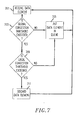
- FIG. 7 shows a flow chart of a process for congestion control, in accordance with the principles of the invention. This process manages the operation of queue 301 and server 302 in such a way as to effectively achieve the sub-queue structure of FIG. 5 .
- step 701 the process is entered in step 701 when a data element, uniquely associated with one of channels 1 to M, arrives at queue 301 ( FIG. 4 ).
- conditional branch point 703 tests to determine if global congestion threshold 403 is exceeded. This test is performed by determining if the total number of bytes already in queue 301 and the number of bytes in the just-received data element is greater than the value of global congestion threshold 403.
- global congestion threshold 403 is a fixed threshold indicating a predetermined queue length. The manner in which the value of global congestion threshold 403 may be selected is discussed hereinbelow. If the test result in step 703 is NO, there is no congestion in queue 301. Therefore, control passes to step 705 and the just-received data element is stored in queue 301 to await service by server 302. Thereafter, the process returns to step 701 to receive a new data element.
- test result in step 703 is YES, there is congestion at queue 301. Therefore, control passes to conditional branch point 709, which tests to determine if the local congestion threshold 503-i ( FIG. 5 ) for the queue 501-i of the channel associated with the just-received data element is exceeded. The manner in which the values of local congestion thresholds 503-i is discussed hereinbelow. If the test result in step 709 is NO, the channel associated with the just-received data element is not one of the major causes of the congestion at queue 301. Therefore, control passes to step 705 and, again, the just-received data element is placed in queue 301 to await service by server 302. Thereafter, the process returns to step 701 to receive a new data element.
- step 709 If the test result in step 709 is YES, the channel associated with the just-received data element is, indeed, one of the major causes of the congestion at queue 301. Therefore, control passes to step 71 and the just-received data element is dropped, or discarded, in an attempt to alleviate the congestion. Thereafter, the process again returns to step 701.
- the process shown in FIG. 7 insures that only those channels that are major causes of congestion, i.e., those which introduce data elements into network 100 at a rate which greatly exceeds their contracted for bandwidth so that global congestion at a resource results, will have their data elements dropped. It further guarantees that each channel can achieve at least its contracted-for bandwidth at all times.
- FIG. 8 shows a histogram resulting from the use of the congestion control process shown in FIG. 7 .
- ⁇ ' is a threshold in the ⁇ i domain for a particular number of active channels.
- a channel's ⁇ i exceeds ⁇ ', this indicates that the channel i is major causation of congestion at the resource.
- the resource does not have the capability to service all the data elements that are arriving from that channel. Therefore, channels that have a ⁇ i beyond ⁇ will, sooner or later, have data elements dropped in step 711 ( FIG. 7 ).
- data elements for those channels that do not exceed the level of ⁇ ' at any time will not be dropped, even if there is congestion at the resource, despite the fact that such channels are regularly exceeding their contracted-for bandwidths and thus for which ⁇ i > 1.
- ⁇ ' thus represents a gain in usable bandwidth to the active channels above and beyond their contracted-for bandwidths that can be attained without causing the dropping of data elements. This gain is derived from the bandwidths of those channels that are inactive or are below their contracted-for bandwidth.
- ⁇ ' is dynamic and it varies according to the number of active channels and their respective ⁇ i .
- ⁇ ' can be calculated as follows:
- the foregoing can thus be seen to be the determination of a capability of the resource to service data elements arriving on a particular active channel.
- This capability is determined as a function of at least i) a contracted-for bandwidth for each active channel at the resource, ii) the arrival rate of data elements for the particular active channel and iii) the arrival rates of data elements for each active channel at the resource that is not the particular active channel. Data elements on the particular active channel are dropped if the determined capability of the resource is exceeded.
- This can be contrasted with the prior art, which examines the contracted-for bandwidth for each active channel and the total arrival rate of data elements at the resource.
- Values for global congestion threshold 403 and local congestion thresholds 503 are best determined by developing initial estimates through the use of well known network design principles and projected traffic conditions. These estimates are then fine tuned by employing observations of the system during actual use. Those skilled in the art will be familiar with the design principles necessary to derive such initial estimates. They will also realize that, because of the myriad possible design goals for such networks, as well as their infinite possible configurations, it is not possible to list or prescribe predetermined calculations for setting global congestion threshold 403 and local congestion thresholds 503. As a result, estimation with observation based corrections that are developed via trial and error is the best available method.
- the initial estimates will be a function of the parameters of the contract. For example, in addition to bandwidth, the contracted-for parameters may include a guaranteed minimum for the allowable maximum length of the queue at each resource.
- the value of global congestion threshold 403 may change over time. For example, it may be adjusted based on to the average queue occupancy. Similarly, the value of local congestion thresholds 503-i may change over time. In still further embodiments, the values of global congestion threshold 403 and local congestion thresholds 503-i may be adjusted every time they are traversed so that they create a hysteresis effect in the determination of the existence of congestion.
Description
- This invention relates to congestion controls for use in data networks.
- Data networks switch elements of data (data elements) such as packets or cells. In such data networks, there typically exist various defined channels, such as virtual circuits, over which the data elements are carried. Each channel shares resources of the network, a resource being, for example, a queue and an associated server. Typically, a minimum bandwidth is assigned to each channel in the network according to a contract between the network provider and an entity to which the channel is assigned. An entity may be a group of data element sources or it may be a single data element source. An association exists between each data element and a channel assigned to its source. The association may be established before, or as, the data element enters the data network.
- Prior data networks, as disclosed in, for example,
EP 0 487 235 , of the type in which a minimum bandwidth is contracted for by each channel have suffered from a variety of problems in their allocation of bandwidth to the active channels at a resource, i.e., those channels at the resource that are carrying data elements at a particular time. One such problem is the so-called fairness problem, i.e., how to fairly share any available excess bandwidth among the active channels. Another problem relates to insuring that the active channels are allowed to actually make use of all of the bandwidth for which they have contracted. This problem arises because it is possible that an end-to-end protocol being employed over a channel may interact with the congestion control mechanisms employed by the network in such a way that a channel's contracted-for bandwidth is never actually achieved. - Additional problems arise in the area of congestion control. Prior congestion control techniques tended, in the face of congestion, to drop data elements from all channels that exceeded their contracted-for bandwidth. This, however, could exacerbate the congestion by causing such channels to retransmit all their dropped data elements. Furthermore, such techniques for data element dropping typically result in the retransmission over a channel of more data elements than were actually dropped. Another problem with prior congestion control techniques is that many of them result in high delays for data elements in those channels that are transmitting within their contracted-for bandwidth. Lastly, errors that occur in the estimation of the actual bandwidth being used by each channel may cause a particular channel's data elements to be dropped even though such a channel is actually within its contracted-for bandwidth. This unnecessary data element dropping results in additional data element retransmissions and, potentially, additional congestion.
- A first aspect of the invention is defined in
claim 1. - A second aspect of the invention is defined in claim 3.
- In the drawing:
-
FIG. 1 shows an exemplary network embodying the principles of the invention; -
FIG. 2 shows an expanded view of two of the nodes of the network shown in F1G. 1; -
FIG. 3 shows transmission queues and servers for the nodes shown inFIG. 2 ; - FIG- 4 shows another view of one queue and server from
FIG. 3 ; -
FIG. 5 is a conceptual model showing queue and server ofFIG. 4 as being comprised of several smaller queues and corresponding servers; -
FIG. 6 shows a table of proportional service rates for each of M channels of the queue and server shown inFIG. 3 ; -
FIG. 7 shows a flow chart of a process for congestion control, in accordance with the principles of the invention; and -
FIG. 8 shows a histogram from which helps illustrate some of the characteristics of the congestion control process shown inFIG. 7 . -
FIG. 1 showsexemplary data network 100 in which the present invention is used.Data network 100 includesnodes 101 through 117,high speed links 118,low speed links 119,data sources 120 andaccess links 121.High speed links 118 andlow speed links 119interconnect nodes 101 through 117, in the manner shown.Access links 121 connectdata sources 120 to various ones of the nodes ofdata network 100.Data network 100 switches data elements, e.g., either packets or cells. Ifdata network 100 switches packets, in particular, it is called a packet switched network. The data elements are supplied fromdata sources 120. Each data element contains an indication that uniquely identifies a channel to which it is assigned. -
FIG. 2 shows an expanded view ofnodes Node 102 includes access interface resource (A) 201, embodying aspects of the invention, and internal communications resources (I) 202, embodying aspects of the invention.Node 102 includes two of the internal communications resources (I) 202, one for eachhigh speed link 118 terminating atnode 102.Node 104 includes the five internal communications resources (1) 202 shown, one for eachhigh speed link 118 terminating atnode 104. Access interface resource (A) 201 controls communication of data elements between data network anddata sources 120 overaccess links 121. Each internal communications resource (I) 202 controls the communications of data elements withindata network 100 over the internal links to which it is connected, which in the case ofnodes high speed links 118. Similarly, internal communications resources (1) 202 within other nodes control the communication of data elements withindata network 100 overlow speed links 119. Access interface resource (A) 201 and internal communications resources (I) 202 can both employ the service discipline and congestion control techniques described below, pursuant to the invention. -
FIG. 3 showstransmission queues 301 andservers 302 within internal communications resource (I) 202 for a single direction of transmission. Data elements for transmission viahigh speed link 118 are queued inqueue 301 prior to service and transmission byserver 302.Server 302 can either transmit data elements out of the node, e.g., to a next node or to a data source, or route the data element to an appropriate resource within the node overlinks 204. Typicallyqueue 301 andserver 302 are made up of a processor and its associated memory. The memory stores queued data elements while the processor manages the queue and performs the servicing functions. -
FIG. 4 is a view of atypical queue 301 andserver 302 ofFIG. 3 . In data networks such asdata network 100, there typically exist various defined channels, such as virtual circuits, over which the data elements are carried. Queue 301 may receive data elements that were supplied by any channel ofnetwork 100. - A minimum bandwidth is assigned to each channel in the network according to a contract between the network provider and an entity to which the channel is assigned. An entity may be a group of
user data sources 120 or it may be a singleuser data source 120. An association exists between a data element and a channel assigned to the one ofuser data sources 120 that supplied the data element. The association may be established either before the data element enters the data network or in the one of access interface resources (A) 201 at which the data element is processed intodata network 100. After being processed intodata network 100, each data element is routed to its destinationuser data source 120. - Each data element may pass through several of
nodes 101 through 117 before reaching its destination. As a result, packets from different channels may simultaneously be waiting inqueue 301 of resource for service by the associatedserver 302. Furthermore, the data elements of a single channel that are arriving atqueue 301 may have traveled over physically diverse routes if they were supplied from different ones of user data sources 120. - As noted, an active channel at a resource is a channel that is carrying data elements at a particular time. Therefore, a channel is an active channel at a resource if at least one data element has been received from the channel and that data element is either currently a) awaiting service in
queue 301 or b) is being served byserver 302. There are M channels defined in data network (FIG. 1 ). Each channel is indicated by the subscript i, where i = I, ..., M. Not all the channels need be active at any particular time or at any particular resource. The data elements of a channel active at a resource arrive that resource at the rate of λi. Eachserver 302 is capable of serving and transmitting data elements at its own predetermined maximum service rate µ.FIG. 4 also showsglobal congestion threshold 403, which will be discussed further below. - The arrangement as thus far described is standard in the art. However,
queue 301 andserver 302 are logically transformed, as shown inFIG. 5 , into several smaller queues 501-1 through 501-N and corresponding servers 502-1 through 502-N. N is equal to the number of active channels in thequeue 301 andserver 302 combination. Each queue 501-i is associated with a single active channel and it only contains data elements owned by that channel. Thus, each queue 501-i can be thought of as a sub-queue dedicated to the data elements of its particular associated active channel. Correspondingly, each server 502-i has its own associated service rate µi and it only processes data elements from the queue 501-i of its particular associated active channel. - In preferred embodiments of the invention,
server 302 implements the known head-of-the-line weighted round-robin service discipline for serving data elements from each active channel. In accordance with that discipline, data elements are strictly separated on the basis of the channel to which they are associated andserver 302 processes a predetermined number of data elements from the head of each active channel, after whichserver 302 proceeds to process data elements from the head of the next active channel. The number of data elements processed from each particular active channel is a function of the channel's contracted-for bandwidth, hence the discipline is "weighted". This discipline is equivalent to having each server 502-i serve its data elements according to the well known first-in-first-out (FIFO) service discipline with rate µi with the operation of each server 502-i being independent of the service of any other server 502-i. This is because the values of the various µi vary as a function of the number of active channels and their respective contracted-for bandwidths. Each µi is also a function of µ ofserver 302. - The proportional service rate for a channel is a representation of the channel's contracted-for bandwidth, and it is directly proportional thereto.
FIG. 6 shows a table of proportional service rates vi for each ofchannels 1, ..., M ofdata network 100. In the example ofFIG. 6 , each channel has the same contracted-for bandwidth, except that channel M has a contracted-for bandwidth that is twice that of any other channel. - At any time, a particular µi is determined by multiplying the associated proportional service rate vi by µ and dividing the result by the sum of the proportional service rates of the active channels. As an example, assume that N = 3 and that the active channels are 1, 2 and M. From
FIG. 6 , the proportional service rate for each ofchannels 
-
FIG. 5 also shows local congestion thresholds 503-i, designated as local congestion threshold 503- 1 through 503-N. These thresholds, which need not be the same, indicate when a sub-queue for a particular channel is considered congested, as described more fully below. -
FIG. 7 shows a flow chart of a process for congestion control, in accordance with the principles of the invention. This process manages the operation ofqueue 301 andserver 302 in such a way as to effectively achieve the sub-queue structure ofFIG. 5 . - In particular, the process is entered in
step 701 when a data element, uniquely associated with one ofchannels 1 to M, arrives at queue 301 (FIG. 4 ). Next,conditional branch point 703 tests to determine ifglobal congestion threshold 403 is exceeded. This test is performed by determining if the total number of bytes already inqueue 301 and the number of bytes in the just-received data element is greater than the value ofglobal congestion threshold 403. For this embodiment,global congestion threshold 403 is a fixed threshold indicating a predetermined queue length. The manner in which the value ofglobal congestion threshold 403 may be selected is discussed hereinbelow. If the test result instep 703 is NO, there is no congestion inqueue 301. Therefore, control passes to step 705 and the just-received data element is stored inqueue 301 to await service byserver 302. Thereafter, the process returns to step 701 to receive a new data element. - If the test result in
step 703 is YES, there is congestion atqueue 301. Therefore, control passes toconditional branch point 709, which tests to determine if the local congestion threshold 503-i (FIG. 5 ) for the queue 501-i of the channel associated with the just-received data element is exceeded. The manner in which the values of local congestion thresholds 503-i is discussed hereinbelow. If the test result instep 709 is NO, the channel associated with the just-received data element is not one of the major causes of the congestion atqueue 301. Therefore, control passes to step 705 and, again, the just-received data element is placed inqueue 301 to await service byserver 302. Thereafter, the process returns to step 701 to receive a new data element. - If the test result in
step 709 is YES, the channel associated with the just-received data element is, indeed, one of the major causes of the congestion atqueue 301. Therefore, control passes to step 71 and the just-received data element is dropped, or discarded, in an attempt to alleviate the congestion. Thereafter, the process again returns to step 701. - It directly follows from queuing theory that congestion must eventually result if the quantity

- Advantageously, the process shown in
FIG. 7 insures that only those channels that are major causes of congestion, i.e., those which introduce data elements intonetwork 100 at a rate which greatly exceeds their contracted for bandwidth so that global congestion at a resource results, will have their data elements dropped. It further guarantees that each channel can achieve at least its contracted-for bandwidth at all times. This can be better understood by consideringFIG. 8 , which shows a histogram resulting from the use of the congestion control process shown inFIG. 7 . Each of the active channels is represented by a respective bar in the histogram. The bars are arranged in decreasing order of the values of ρi of the channels that they represent, where
- ρ' is a threshold in the ρi domain for a particular number of active channels. When, for a particular resource at a particular point in time, a channel's ρ i exceeds ρ', this indicates that the channel i is major causation of congestion at the resource. As such, the resource does not have the capability to service all the data elements that are arriving from that channel. Therefore, channels that have a ρi beyond ρ will, sooner or later, have data elements dropped in step 711 (
FIG. 7 ). However, advantageously, data elements for those channels that do not exceed the level of ρ' at any time will not be dropped, even if there is congestion at the resource, despite the fact that such channels are regularly exceeding their contracted-for bandwidths and thus for which ρi > 1. ρ' thus represents a gain in usable bandwidth to the active channels above and beyond their contracted-for bandwidths that can be attained without causing the dropping of data elements. This gain is derived from the bandwidths of those channels that are inactive or are below their contracted-for bandwidth. - The value of ρ' is dynamic and it varies according to the number of active channels and their respective λi. Thus, while a channel exhibiting a particular type of data element supplying pattern may not be a major cause of congestion at a particular time, at a later time, the same supplying pattern may cause the channel to become a major cause of congestion. Such a change would result because of changes in the data element supplying pattern of other channels in the system. At any point in time, ρ' can be calculated as follows:
- 1) First it is necessary to find a value J such that

and
where j is an index ranging from 1 to N that specifies the active channels in accordance with increasing values of pi, as shown inFIG. 6 . - 2) Next, a value of x is found such that

- 3) Finally, ρ' is determined from ρ' = ρj + x.
- The foregoing can thus be seen to be the determination of a capability of the resource to service data elements arriving on a particular active channel. This capability is determined as a function of at least i) a contracted-for bandwidth for each active channel at the resource, ii) the arrival rate of data elements for the particular active channel and iii) the arrival rates of data elements for each active channel at the resource that is not the particular active channel. Data elements on the particular active channel are dropped if the determined capability of the resource is exceeded. This can be contrasted with the prior art, which examines the contracted-for bandwidth for each active channel and the total arrival rate of data elements at the resource.
- Values for
global congestion threshold 403 andlocal congestion thresholds 503 are best determined by developing initial estimates through the use of well known network design principles and projected traffic conditions. These estimates are then fine tuned by employing observations of the system during actual use. Those skilled in the art will be familiar with the design principles necessary to derive such initial estimates. They will also realize that, because of the myriad possible design goals for such networks, as well as their infinite possible configurations, it is not possible to list or prescribe predetermined calculations for settingglobal congestion threshold 403 andlocal congestion thresholds 503. As a result, estimation with observation based corrections that are developed via trial and error is the best available method. The initial estimates will be a function of the parameters of the contract. For example, in addition to bandwidth, the contracted-for parameters may include a guaranteed minimum for the allowable maximum length of the queue at each resource. - In other embodiments, the value of
global congestion threshold 403 may change over time. For example, it may be adjusted based on to the average queue occupancy. Similarly, the value of local congestion thresholds 503-i may change over time. In still further embodiments, the values ofglobal congestion threshold 403 and local congestion thresholds 503-i may be adjusted every time they are traversed so that they create a hysteresis effect in the determination of the existence of congestion.
Claims (6)
- Apparatus for controlling congestion at resources of a data network in which channels have predetermined contracted-for bandwidths and each data element in said network is associated with one of said channels, each of a plurality of said resources comprising:a queue for temporarily storing data elements;a data element server for serving data elements stored in said queue;means for maintaining at said each resource a global congestion threshold (403) for said resource, said threshold being less than the maximum capacity of said queue;means for maintaining at said each resource a local congestion threshold (503) for each channel, characterised in the local congestion threshold varying according to the number of active channels and their respective arrival rates λi, where λi is the rate at which data elements arrive at the ith channel; andmeans for dropping an arriving data element that causes both a) the global congestion threshold of said resource and b) the local congestion threshold of the channel associated with said data element to be exceeded, so that said arriving data element is not stored in said queue, said dropping being independent of any indication, stored for said data element, that said data element exceeded the contracted-for bandwidth of the channel on which it arrived.
- An apparatus as claimed in claim 1 and adapted to calculate the local congestion threshold, ρ', based on a formula:

wherein J is a value such that
and
wherein x is a value such that
- A method of performing congestion control of data elements in a data network having internal resources, each of said internal resources comprising a queue and a server, and each data element being associated with a particular channel having a predetermined contracted-for bandwidth, the method characterized by the steps of:making a determination (703) that a global congestion threshold (403) for an internal resource is exceeded, said global congestion threshold being less than the maximum capacity of the queue of said internal resource; andin response to said determination, dropping (711) a data element arriving at said internal resource without ever placing said data element in said queue of said internal resource when said arriving data element causes a local congestion threshold (503) to be exceeded, wherein the local congestion threshold (503) varies according to the number of active channels and their respective arrival rates λi, where λi is the rate at which data elements arrive at the ith channel, said dropping being independent of any indication, stored for said data element, that said data element exceeded the contracted-for bandwidth of the channel on which it arrived.
- A method as defined in claim 3 wherein said internal resource employs a weighted round-robin service discipline.
- A method as defined in claim 3 wherein data elements are dropped, when received from a particular channel or channels which have most exceeded their bandwidth allocations over a predetermined time interval on a proportional basis with respect to their respective associated bandwidth allocations.
- A method as claimed in claim 3, 4 or 5 wherein the local congestion threshold, ρ', is calculated based on a formula:

wherein J is a value such that
and
wherein x is a value such that
wherein j, J and N are integers, λ i represents a rate at which the data elements of the ith active channel at said each resource arrive, µ represents a rate at which the data elements are processed at said each resource and υ i represents a proportional service rate associated with the ith channel.
Applications Claiming Priority (2)
| Application Number | Priority Date | Filing Date | Title |
|---|---|---|---|
| US07/906,964 US5335224A (en) | 1992-06-30 | 1992-06-30 | Service guarantees/congestion control in high speed networks |
| EP93305016A EP0577359B1 (en) | 1992-06-30 | 1993-06-28 | Congestion control in high speed networks |
Related Parent Applications (2)
| Application Number | Title | Priority Date | Filing Date |
|---|---|---|---|
| EP93305016.3 Division | 1993-06-28 | ||
| EP93305016A Division EP0577359B1 (en) | 1992-06-30 | 1993-06-28 | Congestion control in high speed networks |
Publications (3)
| Publication Number | Publication Date |
|---|---|
| EP1670194A1 EP1670194A1 (en) | 2006-06-14 |
| EP1670194B1 true EP1670194B1 (en) | 2013-02-27 |
| EP1670194B8 EP1670194B8 (en) | 2013-04-17 |
Family
ID=25423313
Family Applications (2)
| Application Number | Title | Priority Date | Filing Date |
|---|---|---|---|
| EP93305016A Expired - Lifetime EP0577359B1 (en) | 1992-06-30 | 1993-06-28 | Congestion control in high speed networks |
| EP06111782.6A Expired - Lifetime EP1670194B8 (en) | 1992-06-30 | 1993-06-28 | Service guarantee and congestion control in high speed networks |
Family Applications Before (1)
| Application Number | Title | Priority Date | Filing Date |
|---|---|---|---|
| EP93305016A Expired - Lifetime EP0577359B1 (en) | 1992-06-30 | 1993-06-28 | Congestion control in high speed networks |
Country Status (5)
| Country | Link |
|---|---|
| US (1) | US5335224A (en) |
| EP (2) | EP0577359B1 (en) |
| JP (1) | JPH0690255A (en) |
| CA (1) | CA2099170C (en) |
| DE (1) | DE69334005T2 (en) |
Cited By (1)
| Publication number | Priority date | Publication date | Assignee | Title |
|---|---|---|---|---|
| WO2016068839A1 (en) * | 2014-10-27 | 2016-05-06 | Hewlett Packard Enterprise Development Lp | Determining to process network protocol packets |
Families Citing this family (44)
| Publication number | Priority date | Publication date | Assignee | Title |
|---|---|---|---|---|
| GB9326276D0 (en) * | 1993-12-23 | 1994-02-23 | Newbridge Network Corp | Frame relay interface |
| US5617409A (en) * | 1994-01-28 | 1997-04-01 | Digital Equipment Corporation | Flow control with smooth limit setting for multiple virtual circuits |
| DE4405262C1 (en) * | 1994-02-18 | 1995-11-09 | Siemens Ag | Method and circuit arrangement for controlling the transmission of message blocks within a transmission system |
| US5475682A (en) * | 1994-06-10 | 1995-12-12 | At&T Corp. | Method of regulating backpressure traffic in a packet switched network |
| US5553061A (en) * | 1994-06-27 | 1996-09-03 | Loral Fairchild Corporation | Packet processor having service priority and loss priority features |
| US5487061A (en) * | 1994-06-27 | 1996-01-23 | Loral Fairchild Corporation | System and method for providing multiple loss and service priorities |
| US5455826A (en) * | 1994-06-28 | 1995-10-03 | Oezveren; Cueneyt M. | Method and apparatus for rate based flow control |
| US5475813A (en) * | 1994-07-18 | 1995-12-12 | International Business Machines Corporation | Routing transactions in the presence of failing servers |
| US5699520A (en) * | 1994-08-25 | 1997-12-16 | Hewlett-Packard Company | Flow control apparatus and method for a computer interconnect using adaptive credits and flow control tags |
| US5594729A (en) * | 1994-09-23 | 1997-01-14 | Lucent Technologies Inc. | System and method for employing single-bit feedback control within a variable bit rate data transmission network |
| CA2138061A1 (en) * | 1994-12-14 | 1996-06-15 | Mark Wolff | Fair allocation of excess resources |
| GB9520807D0 (en) * | 1995-10-11 | 1995-12-13 | Newbridge Networks Corp | Fair queue servicing using dynamic weights |
| US6091725A (en) | 1995-12-29 | 2000-07-18 | Cisco Systems, Inc. | Method for traffic management, traffic prioritization, access control, and packet forwarding in a datagram computer network |
| US5689500A (en) * | 1996-01-16 | 1997-11-18 | Lucent Technologies, Inc. | Multistage network having multicast routing congestion feedback |
| US6222822B1 (en) * | 1996-04-23 | 2001-04-24 | Cisco Systems, Incorporated | Method for optimizing a digital transmission network operation through transient error monitoring and control and system for implementing said method |
| US6185223B1 (en) * | 1996-12-04 | 2001-02-06 | Conexant Systems, Inc. | Apparatus and method for providing fire wall protection for systems in communication with an a synchronous transfer mode system |
| US6009097A (en) * | 1997-04-04 | 1999-12-28 | Lucent Technologies Inc. | System for routing packet switched traffic |
| US6148001A (en) * | 1997-06-12 | 2000-11-14 | Nokia Telecommunications, Oy | Multipoint-to-point system which multiplexes complete packets comprised of ATM cells on to a single virtual channel connection |
| GB2327317B (en) | 1997-07-11 | 2002-02-13 | Ericsson Telefon Ab L M | Access control and resourse reservation in a communications network |
| US6151299A (en) * | 1997-07-24 | 2000-11-21 | Nortel Networks Corporation | Method and apparatus for enhanced partial packet discard |
| US6370121B1 (en) | 1998-06-29 | 2002-04-09 | Cisco Technology, Inc. | Method and system for shortcut trunking of LAN bridges |
| US6229813B1 (en) * | 1998-11-25 | 2001-05-08 | Alcatel Canada Inc. | Pointer system for queue size control in a multi-task processing application |
| US6504818B1 (en) * | 1998-12-03 | 2003-01-07 | At&T Corp. | Fair share egress queuing scheme for data networks |
| GB2349296B (en) * | 1999-04-21 | 2001-04-04 | 3Com Corp | Reduction of imbalance in transmit traffic queues in a network switch |
| GB2353172B (en) | 1999-08-04 | 2001-09-26 | 3Com Corp | Network switch including bandwidth allocation controller |
| US6498781B1 (en) | 1999-08-13 | 2002-12-24 | International Business Machines Corporation | Self-tuning link aggregation system |
| US6657960B1 (en) | 1999-11-23 | 2003-12-02 | International Business Machines Corporation | Method and system for providing differentiated services in computer networks |
| JP2001197119A (en) * | 2000-01-13 | 2001-07-19 | Nec Corp | Server device, network system and receiving load control method therefor |
| US6842783B1 (en) | 2000-02-18 | 2005-01-11 | International Business Machines Corporation | System and method for enforcing communications bandwidth based service level agreements to plurality of customers hosted on a clustered web server |
| US6954429B2 (en) * | 2000-04-05 | 2005-10-11 | Dyband Corporation | Bandwidth control system |
| US6856595B1 (en) * | 2000-05-19 | 2005-02-15 | Mosaid Technologies, Inc. | Method and apparatus for providing input back pressure in an output buffered switch |
| FI20002320A (en) * | 2000-10-20 | 2002-04-21 | Nokia Corp | Blocking Management in Wireless Telecommunication Networks |
| US20020146004A1 (en) * | 2001-04-04 | 2002-10-10 | Adtran, Inc. | Nominal data flow path-based, virtual function configured frame relay state machine |
| US6973529B2 (en) * | 2001-09-28 | 2005-12-06 | International Business Machines Corporation | Multiple I/O path selection among disparate channel paths |
| US7480239B1 (en) | 2001-11-27 | 2009-01-20 | Cisco Technology, Inc. | Method and apparatus for true priority based connection establishment within a PNNI ATM network |
| JP2003186776A (en) * | 2001-12-13 | 2003-07-04 | Hitachi Ltd | Congestion control system |
| US7283470B1 (en) * | 2002-01-25 | 2007-10-16 | Juniper Networks, Inc. | Systems and methods for dropping data using a drop profile |
| US7161904B2 (en) * | 2002-06-04 | 2007-01-09 | Fortinet, Inc. | System and method for hierarchical metering in a virtual router based network switch |
| US7177913B2 (en) * | 2002-12-05 | 2007-02-13 | Intel Corporation | Method, system, and program for adding operations identifying data packets to structures based on priority levels of the data packets |
| US7532574B1 (en) | 2003-10-02 | 2009-05-12 | Cisco Technology, Inc. | Method and apparatus for improved priority based connection establishment within a PNNI ATM network |
| US7545744B2 (en) * | 2005-03-31 | 2009-06-09 | Alcatel | Method and system for fairly adjusting bandwidth among distributed network elements |
| US7733894B1 (en) * | 2005-12-14 | 2010-06-08 | Juniper Networks, Inc. | Dynamic queue management |
| US10425336B2 (en) * | 2011-06-24 | 2019-09-24 | Centurylink Intellectual Property Llc | System and method of adaptive congestion management |
| CN107016008B (en) * | 2016-06-06 | 2020-06-09 | 阿里巴巴集团控股有限公司 | Information processing method and device and dynamic information display method and device |
Family Cites Families (8)
| Publication number | Priority date | Publication date | Assignee | Title |
|---|---|---|---|---|
| US4475192A (en) * | 1982-02-16 | 1984-10-02 | At&T Bell Laboratories | Data packet flow control scheme for switching networks |
| US4734907A (en) * | 1985-09-06 | 1988-03-29 | Washington University | Broadcast packet switching network |
| US4769811A (en) * | 1986-12-31 | 1988-09-06 | American Telephone And Telegraph Company, At&T Bell Laboratories | Packet switching system arranged for congestion control |
| US4953157A (en) * | 1989-04-19 | 1990-08-28 | American Telephone And Telegraph Company | Programmable data packet buffer prioritization arrangement |
| JPH03205937A (en) * | 1990-01-05 | 1991-09-09 | Hitachi Ltd | Device and method for controlling flow rate of packet exchange |
| JPH0430641A (en) * | 1990-05-24 | 1992-02-03 | Nec Corp | Cell traffic monitor system for in-network input restriction |
| JPH0767107B2 (en) * | 1990-08-24 | 1995-07-19 | 日本電気株式会社 | ATM cell flow monitor / control cell counter circuit |
| EP0487235B1 (en) * | 1990-11-21 | 1999-02-03 | AT&T Corp. | Bandwidth and congestion management in accessing broadband ISDN networks |
-
1992
- 1992-06-30 US US07/906,964 patent/US5335224A/en not_active Expired - Lifetime
-
1993
- 1993-06-25 CA CA002099170A patent/CA2099170C/en not_active Expired - Lifetime
- 1993-06-28 EP EP93305016A patent/EP0577359B1/en not_active Expired - Lifetime
- 1993-06-28 DE DE69334005T patent/DE69334005T2/en not_active Expired - Lifetime
- 1993-06-28 EP EP06111782.6A patent/EP1670194B8/en not_active Expired - Lifetime
- 1993-06-29 JP JP18227793A patent/JPH0690255A/en active Pending
Cited By (1)
| Publication number | Priority date | Publication date | Assignee | Title |
|---|---|---|---|---|
| WO2016068839A1 (en) * | 2014-10-27 | 2016-05-06 | Hewlett Packard Enterprise Development Lp | Determining to process network protocol packets |
Also Published As
| Publication number | Publication date |
|---|---|
| US5335224A (en) | 1994-08-02 |
| DE69334005D1 (en) | 2006-05-24 |
| EP1670194A1 (en) | 2006-06-14 |
| JPH0690255A (en) | 1994-03-29 |
| CA2099170A1 (en) | 1993-12-31 |
| EP1670194B8 (en) | 2013-04-17 |
| DE69334005T2 (en) | 2007-01-25 |
| EP0577359B1 (en) | 2006-04-12 |
| CA2099170C (en) | 1999-12-14 |
| EP0577359A3 (en) | 1998-04-01 |
| EP0577359A2 (en) | 1994-01-05 |
Similar Documents
| Publication | Publication Date | Title |
|---|---|---|
| EP1670194B1 (en) | Service guarantee and congestion control in high speed networks | |
| AU602379B2 (en) | Packet switching system arranged for congestion control through bandwidth management | |
| EP0275679B1 (en) | Packet switching system arranged for congestion control | |
| EP0763915B1 (en) | Packet transfer device and method adaptive to a large number of input ports | |
| EP0872988B1 (en) | A method for supporting per-connection queuing for feedback-controlled traffic | |
| US7046631B1 (en) | Method and apparatus for provisioning traffic dedicated cores in a connection oriented network | |
| US6526060B1 (en) | Dynamic rate-based, weighted fair scheduler with explicit rate feedback option | |
| US6765873B1 (en) | Connections bandwidth right sizing based on network resources occupancy monitoring | |
| EP0719012B1 (en) | Traffic management and congestion control for packet-based network | |
| EP1798915B1 (en) | Packet forwarding device avoiding packet loss of out of profile packets in the shaper by remarking and redirecting the packet to a lower priority queue | |
| US6122254A (en) | Method and apparatus for network flow control with perceptive parameters | |
| JP2783469B2 (en) | Method and apparatus for adjusting window size in packet transmission network | |
| US6396843B1 (en) | Method and apparatus for guaranteeing data transfer rates and delays in data packet networks using logarithmic calendar queues | |
| US5629936A (en) | Control of consecutive packet loss in a packet buffer | |
| US6980516B1 (en) | Soft, prioritized early packet discard system | |
| Chao et al. | Design of a generalized priority queue manager for ATM switches | |
| US6587436B1 (en) | Method and apparatus for allocation of available bandwidth | |
| US5956322A (en) | Phantom flow control method and apparatus | |
| Keshav et al. | Design and analysis of a flow control algorithm for a network of rate allocating servers | |
| US7218608B1 (en) | Random early detection algorithm using an indicator bit to detect congestion in a computer network | |
| EP1381192A1 (en) | Improved phantom flow control method and apparatus | |
| KR100482687B1 (en) | Congestion Control Apparatus And Method For UBR Service In ATM Switch | |
| KR100381378B1 (en) | ATM Cell Scheduler And Scheduling Method | |
| WO1998043395A9 (en) | Improved phantom flow control method and apparatus | |
| JP3132719B2 (en) | Usage parameter control circuit |
Legal Events
| Date | Code | Title | Description |
|---|---|---|---|
| PUAI | Public reference made under article 153(3) epc to a published international application that has entered the european phase |
Free format text: ORIGINAL CODE: 0009012 |
|
| 17P | Request for examination filed |
Effective date: 20060330 |
|
| AC | Divisional application: reference to earlier application |
Ref document number: 0577359 Country of ref document: EP Kind code of ref document: P |
|
| AK | Designated contracting states |
Kind code of ref document: A1 Designated state(s): AT BE BG CH CY CZ DE DK EE ES FI FR GB GR HU IE IS IT LI LT LU LV MC NL PL PT RO SE SI SK TR |
|
| AX | Request for extension of the european patent |
Extension state: AL BA HR MK YU |
|
| REG | Reference to a national code |
Ref country code: HK Ref legal event code: DE Ref document number: 1086407 Country of ref document: HK |
|
| AKX | Designation fees paid |
Designated state(s): DE FR GB IT |
|
| 17Q | First examination report despatched |
Effective date: 20070808 |
|
| GRAP | Despatch of communication of intention to grant a patent |
Free format text: ORIGINAL CODE: EPIDOSNIGR1 |
|
| RIN1 | Information on inventor provided before grant (corrected) |
Inventor name: COLE, ROBERT G Inventor name: FENDICK, KERRY W. Inventor name: RODRIGUES, MANOEL A. |
|
| GRAS | Grant fee paid |
Free format text: ORIGINAL CODE: EPIDOSNIGR3 |
|
| REG | Reference to a national code |
Ref country code: DE Ref legal event code: R079 Ref document number: 69334375 Country of ref document: DE Free format text: PREVIOUS MAIN CLASS: H04L0012560000 Ipc: H04Q0011040000 |
|
| GRAA | (expected) grant |
Free format text: ORIGINAL CODE: 0009210 |
|
| AC | Divisional application: reference to earlier application |
Ref document number: 0577359 Country of ref document: EP Kind code of ref document: P |
|
| AK | Designated contracting states |
Kind code of ref document: B1 Designated state(s): DE FR GB IT |
|
| REG | Reference to a national code |
Ref country code: GB Ref legal event code: FG4D |
|
| RIC1 | Information provided on ipc code assigned before grant |
Ipc: H04Q 11/04 20060101AFI20130121BHEP |
|
| RAP2 | Party data changed (patent owner data changed or rights of a patent transferred) |
Owner name: AT&T INTELLECTUAL PROPERTY II, L.P. |
|
| REG | Reference to a national code |
Ref country code: DE Ref legal event code: R096 Ref document number: 69334375 Country of ref document: DE Effective date: 20130425 |
|
| REG | Reference to a national code |
Ref country code: DE Ref legal event code: R071 Ref document number: 69334375 Country of ref document: DE |
|
| REG | Reference to a national code |
Ref country code: DE Ref legal event code: R071 Ref document number: 69334375 Country of ref document: DE |
|
| REG | Reference to a national code |
Ref country code: GB Ref legal event code: PE20 Expiry date: 20130627 |
|
| PG25 | Lapsed in a contracting state [announced via postgrant information from national office to epo] |
Ref country code: GB Free format text: LAPSE BECAUSE OF EXPIRATION OF PROTECTION Effective date: 20130627 |
|
| PLBE | No opposition filed within time limit |
Free format text: ORIGINAL CODE: 0009261 |
|
| STAA | Information on the status of an ep patent application or granted ep patent |
Free format text: STATUS: NO OPPOSITION FILED WITHIN TIME LIMIT |
|
| REG | Reference to a national code |
Ref country code: HK Ref legal event code: WD Ref document number: 1086407 Country of ref document: HK |
|
| 26N | No opposition filed |
Effective date: 20131128 |
|
| REG | Reference to a national code |
Ref country code: DE Ref legal event code: R097 Ref document number: 69334375 Country of ref document: DE Effective date: 20131128 |
|
| PG25 | Lapsed in a contracting state [announced via postgrant information from national office to epo] |
Ref country code: DE Free format text: LAPSE BECAUSE OF EXPIRATION OF PROTECTION Effective date: 20130629 |