EP1670108A1 - Arc monitoring system - Google Patents
Arc monitoring system Download PDFInfo
- Publication number
- EP1670108A1 EP1670108A1 EP04787964A EP04787964A EP1670108A1 EP 1670108 A1 EP1670108 A1 EP 1670108A1 EP 04787964 A EP04787964 A EP 04787964A EP 04787964 A EP04787964 A EP 04787964A EP 1670108 A1 EP1670108 A1 EP 1670108A1
- Authority
- EP
- European Patent Office
- Prior art keywords
- arc
- arc discharge
- monitor
- image
- cameras
- Prior art date
- Legal status (The legal status is an assumption and is not a legal conclusion. Google has not performed a legal analysis and makes no representation as to the accuracy of the status listed.)
- Granted
Links
Images



Classifications
-
- G—PHYSICS
- G01—MEASURING; TESTING
- G01R—MEASURING ELECTRIC VARIABLES; MEASURING MAGNETIC VARIABLES
- G01R31/00—Arrangements for testing electric properties; Arrangements for locating electric faults; Arrangements for electrical testing characterised by what is being tested not provided for elsewhere
- G01R31/08—Locating faults in cables, transmission lines, or networks
-
- G—PHYSICS
- G01—MEASURING; TESTING
- G01R—MEASURING ELECTRIC VARIABLES; MEASURING MAGNETIC VARIABLES
- G01R31/00—Arrangements for testing electric properties; Arrangements for locating electric faults; Arrangements for electrical testing characterised by what is being tested not provided for elsewhere
- G01R31/12—Testing dielectric strength or breakdown voltage ; Testing or monitoring effectiveness or level of insulation, e.g. of a cable or of an apparatus, for example using partial discharge measurements; Electrostatic testing
- G01R31/1218—Testing dielectric strength or breakdown voltage ; Testing or monitoring effectiveness or level of insulation, e.g. of a cable or of an apparatus, for example using partial discharge measurements; Electrostatic testing using optical methods; using charged particle, e.g. electron, beams or X-rays
-
- G—PHYSICS
- G06—COMPUTING OR CALCULATING; COUNTING
- G06T—IMAGE DATA PROCESSING OR GENERATION, IN GENERAL
- G06T1/00—General purpose image data processing
-
- G—PHYSICS
- G06—COMPUTING OR CALCULATING; COUNTING
- G06T—IMAGE DATA PROCESSING OR GENERATION, IN GENERAL
- G06T7/00—Image analysis
- G06T7/20—Analysis of motion
-
- G—PHYSICS
- G06—COMPUTING OR CALCULATING; COUNTING
- G06T—IMAGE DATA PROCESSING OR GENERATION, IN GENERAL
- G06T7/00—Image analysis
- G06T7/70—Determining position or orientation of objects or cameras
-
- H—ELECTRICITY
- H02—GENERATION; CONVERSION OR DISTRIBUTION OF ELECTRIC POWER
- H02B—BOARDS, SUBSTATIONS OR SWITCHING ARRANGEMENTS FOR THE SUPPLY OR DISTRIBUTION OF ELECTRIC POWER
- H02B3/00—Apparatus specially adapted for the manufacture, assembly, or maintenance of boards or switchgear
Definitions
- the present invention relates to an arc monitor system in which a camera is used to detect a short circuit accident between live lines or a grand fault accident between a live line and the earth (so-called "arc discharge") in various types of electric facilities such as a substation, and then a failure point (a place where the arc discharge is occurred) is identified (referred to as “located” hereinafter) in the electric facilities, and more particularly to an arc monitor system in which multiple cameras are used to capture images of a occurred place of an arc discharge, and the occurred place is located by image processing devices thereby precisely locating and displaying a failed system.
- a conventional arc monitor system is configured to use a general CCTV camera to detect arc light on a generation of an arc, and locates a block of a located place of the failure point based on a screen of a single image (refer to Patent Document 1, for example).
- Patent Document 1 it is not possible to cause an aperture value of a lens to optimally respond to a momentary light emission caused by an arc current (to close the aperture), and a captured image of the arc discharge thus results in a saturated white image in most cases.
- Patent Document 1 JP 11-98628 A
- An arc monitor system is used to locate a occurred place where an arc discharge is occurred in an electric facility, and includes: a plurality of monitor cameras that are arranged at a plurality of places in the electric facility; an image processing device that individually processes images received from the monitor cameras; a control logic section that controls the image processing device; and an operation device that has a display section and an operation section, and is connected to the control logic section.
- the image processing device and the control logic section extract a change in the images received from the monitor cameras in response to a control signal generated from the electric facility on a occurrence of the arc discharge, and then locate a occurred place of the arc discharge.
- the present invention it is possible to increase reliability of the arc detection by locating an arc based on optimal frames from a frame before the arc discharge to a frame immediately after the arc discharge.
- the present invention has been made to solve the above problems, and has an object to provide an arc monitor system capable of locating an arc based on optimal frames by processing multiple frames (thirty frames, for example) from a frame on an arc discharge to a frame immediately after the arc discharge, increasing a precision of detection of arc light regardless of a change in an arc discharge current and a change in an natural environment (such as rain, snow, and fog), and detecting an arc discharge with high reliability.
- an object of the present invention is to provide an arc monitor system in which multiple monitor cameras for near-infrared light obtained by removing visible light are used to evaluate remaining heat after an arc discharge, thereby enabling to monitor an arc current in a wide range, resulting in a reduction of dead angles due to an extension of an arc, and simultaneously, a reduction of reflections on insulators and a ground.
- an object of the present invention is to provide an arc monitor system in which multiple cameras are arranged in orthogonal directions in an electric facility, locating is carried out again on a plan view by means of the triangulation according to locating results based on respective images captured by the cameras, thereby improving the locating precision.
- an object of the present invention is to identify a occurred place of an arc discharge, and to clarify a range to locate a failure point according to a line switching state, thereby finding out a cause of the failure, and quickly recovering from the failure.
- FIG. 1 is a block diagram showing an arc monitor system according to the first embodiment of the present invention.
- multiple arc monitor cameras 1 are arranged to capture images of a occurred place of an arc discharge in an electric facility, and respectively include a near-infrared arc monitor camera equipped with a visible light cut filter.
- Multiple image processing devices 2 are provided corresponding to the respective arc monitor cameras 1, and output a center of gravity of an arc discharge as a two-dimensional (X-Y) coordinate based on the camera image captured by the respective arc monitor cameras 1.
- a control logic section 3 obtains the multiple coordinates of the center of gravity of the arc obtained by the respective image processing devices 2, carries out the triangulation according to arbitrary combinations of the cameras, and locates a place of the arc discharge in a coordinate system on a plan view.
- a PC (personal computer) operation device 4 is connected to the control logic section 3 as an external device, includes a display section and an operation section (described later), and operates the system shown in FIG. 1.
- Multiple machine monitor cameras 5 are arranged to capture images of various machines in the electric facility, and monitor a place of an arc occurred immediately after a generation of an arc discharge accident.
- An image switching device 6 is operated from the PC operation device 4 to switch the images of the respective arc monitor cameras 1, the processed images of the respective image processing devices 2, and the images of the respective machine monitor cameras 5, and outputs switched images.
- Connected to an output terminal side of the image switching device 6 are a VTR 7, a monitor 8, and a four-screen unit 9.
- the VTR 7 is connected bi-directionally to the image switching device 6, and records an image switched and output by the image switching device 6.
- the monitor 8 shows an image switched and output by the image switching device 6.
- the four-screen unit 9 is bi-directionally connected to the image switching device 6, and respective four divided sections of the monitor 8 show images from arbitrary cameras selected by the image switching device 6 according to an operation on the PC operation device 4.
- a bus protection signal 10 is an alarm signal serving as a control signal generated from the electric facility (not shown) on a occurrence of an arc discharge, and is input to the control logic section 3.
- the two-dimensional coordinate output from the respective image processing devices 2 is obtained with respect to an pixel coordinate system with an upper left corner as an origin, for example, when the image of the arc monitor camera 1 is output on the monitor 8.
- FIG. 2 is an explanatory view two-dimensionally showing a camera arrangement in a substation according to the first embodiment of the present invention.
- the arc monitor cameras 1 include fourteen cameras A to N, and are arranged along a periphery in a substation 21. Of these cameras, four cameras A to D are arranged on the right side in the figure, three cameras E to F are arranged on the top side in the figure, four cameras H to K are arranged on the left side in the figure, and three cameras L to N are arranged on the bottom side in the figure.
- FIG. 2 A center point in FIG. 2 is a crossing point of the respective locating results (long dashed double-short dashed lines) of the cameras which most largely captured the arc on the same rows, and is a occurred point of the arc.
- FIG. 2 clearly shows the arc occurred area on a two-dimensional arrangement of the substation 21.
- the machine monitor cameras 5 include eight cameras C1 to C8 respectively arranged in eight directions, for example.
- the respective machine monitor cameras 5 are panning cameras, are automatically preset in a direction in which an arc occurrence is located, and are also manually operated to monitor a occurred place of an arc.
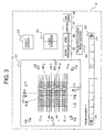
- FIG. 3 is an explanatory view of the display section and the operation section of the PC operation device 4 according to the first embodiment of the present invention.
- the plan view of the substation 21 is shown along with the respective cameras and the results of locating.
- a frame indicator 32 shows frame numbers (-30 to +30) of images for the locating received from the arc monitor cameras 1. In this case, it is intended to use the same frame number for all the arc monitor camera 1 for the locating.
- a single screen switch 33 and a four-screen switch 34 switch a condition of the screen displayed on the monitor 8 shown in FIG. 1 to a single screen display or a four-screen display.
- the state of the screen displayed on the monitor 8 is selected by means of an image selection switch 35 which is used to select an image output from the arc monitor cameras 1 before processing, an image selection switch 36 which is used to select an image obtained after the processing which composes a processed image according to an image processing algorithm (described later) with an actual image output from the camera, a composed image switch 37, and a switch 38 used to switch to a raw image.
- the composed image switch 37 under a condition where it is difficult to locate a occurred place of an arc based on images (such as a fog condition or a night condition), is selected to compose an image of a subject captured in daytime with a processed image used to locate an arc thereby allowing the locating.
- the switch 38 is selected to switch a displayed image to the image (raw image) input from the image processing device 2.
- a failure point locating result indicator 39 includes a window used to display a result of locating a failure point such as "Do not apply voltage on A bus" and "Unable to locate (inconsistency)"
- FIGS. 4 to 6 are explanatory views showing basic operation to locate a failure point according to the first embodiment of the present invention.
- an image record 41 captured by the arc monitor camera 1 is schematically shown as a record processed by the image processing device 2.
- sixty frames 1 to 60 are repeated as a broken arrow shows, and are recorded endlessly.
- a composed image 42 is successively generated, as an image obtained after the processing, by composing the actual image output from the camera with the signal to which the image processing has been applied, in corresponding to the respective frames.
- the composed image 42 is obtained in the image processing device 2 by processing a change in brightness with respect to data of a previous frame.
- This example representatively shows frames 1 to 29 obtained before a generation of an arc, frames 30 to 33 obtained at a time of the generation of the arc, and frames 33 to 60 obtained after the generation of the arc.
- FIG. 6 shows an XY coordinate of a center of gravity 43 of the arc, and a feret's diameter 44.
- the center of gravity 43 of the arc is obtained as follows. First, when a moving object appears in an image, changes occur in pixels corresponding to a portion of the object. On this occasion, if pixels presenting the change are in contact with each other, it is considered that the pixels represent the same object, and thus are combined, and a finally combined area of the change is recognized as a "moving portion". This "moving portion" represents a silhouette of the moving object, and a center of gravity of the silhouette is obtained as the center of gravity 43 of the arc.
- the center of gravity 43 is a position of a center of gravity of brightness obtained after the image processing, and is represented as "+". Moreover, the feret's diameter 44 shows an area (circumscribing rectangle) of a change in the brightness compared with an image of the previous frame.
- the bus protection signal 10 output from the electric facility is input to the control logic section 3.
- the respective processing devices 2 record camera images input from the arc monitor cameras 1 in respective image memories for two seconds, according to a control signal sent from the control logic section 3 in response to the bus protection signal 10.
- a recording period of the camera image is approximately one second for both before and after the generation timing of the bus protection signal 10, namely a total of two seconds. Moreover, since the recording operations for the respective camera images are started by the same bus protection signal 10, the time axes of the respective recorded images coincide.
- the respective image processing devices 2 start the image processing in cooperation with the control logic section 3.
- the arc discharge is located by the following image processing algorithm (1) to (8) executed by the respective image processing devices 2.
- a description will be given of one arc monitor camera 1 as a representative.
- the above processes (1) to (8) are executed for all the arc monitor cameras 1, and coordinate information on the arc discharge is created for all the arc monitor cameras 1.
- Frames to be processed are determined as frames with the minimum feret's diameter of all the recorded sixty frames.
- the coordinate of the center of gravity 43 of the arc is calculated for all the fourteen cameras (cameras A to N shown in FIG. 2), and calculated results are shown as broken lines and the long dashed double-short dashed lines of FIG. 3 along with the result of locating the occurred place of the arc, on the screen of the PC operation device 4.
- the description will be given of an example for a combination of the camera I and the camera M shown in FIG. 2 for the coordinate conversion.
- a line is drawn from the camera I in a direction indicated by this coordinate on the plan view.
- a line is drawn from the camera M.
- the line drawn from the camera I is a perpendicular line of the line drawn from the camera M.
- a position where these two lines cross is an estimated place of the arc discharge.
- the coordinate information on the plan view obtained as a result of the above locating is displayed as shown in FIG. 3.
- multiple points of the generated arc located by the respective pairs of cameras are displayed over the plan view of the substation 21.
- a concentration of the multiple points of the occurred arc is being observed, only when the points of the occurred arc are concentrated in a certain range, a center point thereof may be displayed.
- a height of the occurred arc may be calculated from Y coordinate data for a camera with which an arc can be located to distinguish between a failure of a bus and a failure of a line, and a locating result of the failure point may be shown on the screen according to switched states of the respective switches 33 to 38.
- the PC operation device 4 When the area to locate the arc is determined according to the automatic processing in this way, the PC operation device 4 is operated to select a machine monitoring camera closest to the located arc position, and to direct the camera to the located position, and the located point may be displayed on the screen of the monitor 8, and may be simultaneously recorded in the VTR 7. Namely, the located position of the arc discharge is displayed on the PC operation device 4 and the monitor 8, and simultaneously the machine monitoring camera 5 is rotated to the arc occurring portion, thereby capturing an image immediately after the arc discharge to be displayed on the screens, and recorded in the VTR 7.
- the image processing is used to automatically extract and locate the positions of the arc discharge from the images captured by the arc monitoring cameras. Moreover, on the recognition and the extraction of a light emitting portion (or a heat remaining portion) occurred by an arc discharge, images of multiple frames (30 frames, for example) obtained before the occurrence of the arc discharge to immediately after the occurrence thereof are successively processed to obtain the level and the center of gravity 43 of the arc discharge in the successive images, and transitions of the level and the center of the gravity 43 of the arc discharge are observed to locate a precise position of the arc discharge.
- the multiple arc monitor cameras 1 and other related systems are provided in the substation 21 (electric facility), and the positions of the respective cameras are set such that at least two cameras can capture an arc discharge generated any position in the electric facility, when an arc discharge occurred in the electric facility, positions of the arc discharge located by the respective cameras and image processing systems are precisely calculated by means of the triangulation using the combinations of the images of the multiple cameras, and, as a result, it is possible to surely and precisely identify the position of the arc discharge on the plan view of the electric facility. Moreover, since the occurred place of the arc discharge is extracted three-dimensionally by multiple cameras, and is identified by an XY coordinate, it is possible to locate the position with high precision.
- the number of the frames may be manually specified to simultaneously monitor optimal screens and optimal multiple arc monitor cameras 1.
- a subject to be monitored is hard to observe due to different climate conditions such as fog, rain, and snow, it is possible to identify a occurred place of an arc by composing a background recorded in advance with a screen used to locate the arc.
- the arc monitor camera 1 As an image of the arc monitor camera 1, it is possible to select a recorded image obtained before the processing, an image obtained after the processing, a composed image, and an input image for the image processing (raw image) by selecting operation of the respective switches 35 to 38. Moreover, cameras for near-infrared from which visible light is removed are used as the arc monitor cameras 1. The near-infrared cameras are used to capture images in the electric facility, and influence of sun light which is an interference noise is thus restrained, resulting in increasing the reliability of the arc monitoring.
- a occurred place of an arc discharge is identified, a range to locate a failure point is clarified according to a switching state of a line switch, and, thus, a cause of the accident is quickly investigated, and the failure is quickly recovered.
- a remaining heat energy of smoke extending in a vicinity immediately after an arc discharge can be observed to visually recognize remaining heat in a temporally long period and across a spatially wide range, and it is thus possible to reduce a miss to recognize an arc discharge due to an obstacle present between the arc and the respective arc monitor cameras 1 and a miss to recognize an arc discharge due to a small image captured at a long distance.
- detecting remaining heat after an arc discharge it is possible to detect in a current of an arc discharge in a wide range from 100A to 63kA.
- the multiple image processing devices 2, the PC operation board 4, the VTR 7, and the bus protection signal 10 are used, a single image processing device may be used, other operation board having the same functions as the PC operation board 4 may be used, and other image recording device and a control signal may be used in place of the VTR 7 and the bus protection signal 10.
Landscapes
- Engineering & Computer Science (AREA)
- Physics & Mathematics (AREA)
- General Physics & Mathematics (AREA)
- Theoretical Computer Science (AREA)
- Computer Vision & Pattern Recognition (AREA)
- Manufacturing & Machinery (AREA)
- Multimedia (AREA)
- Power Engineering (AREA)
- Locating Faults (AREA)
- Closed-Circuit Television Systems (AREA)
- Length Measuring Devices By Optical Means (AREA)
- Image Processing (AREA)
- Electric Cable Installation (AREA)
- Image Analysis (AREA)
- Testing Relating To Insulation (AREA)
Abstract
Description
- The present invention relates to an arc monitor system in which a camera is used to detect a short circuit accident between live lines or a grand fault accident between a live line and the earth (so-called "arc discharge") in various types of electric facilities such as a substation, and then a failure point (a place where the arc discharge is occurred) is identified (referred to as "located" hereinafter) in the electric facilities, and more particularly to an arc monitor system in which multiple cameras are used to capture images of a occurred place of an arc discharge, and the occurred place is located by image processing devices thereby precisely locating and displaying a failed system.
- A conventional arc monitor system is configured to use a general CCTV camera to detect arc light on a generation of an arc, and locates a block of a located place of the failure point based on a screen of a single image (refer to
Patent Document 1, for example).
However, it is not possible to cause an aperture value of a lens to optimally respond to a momentary light emission caused by an arc current (to close the aperture), and a captured image of the arc discharge thus results in a saturated white image in most cases. - Patent Document 1: JP 11-98628 A
- Since the conventional arc monitor system tries to capture an image during an arc discharge with a general CCTV camera, there is a problem in that an arc discharge, which is occurred and disappears momentarily, cannot be captured in a state suitable for image processing. Moreover, a place of an arc discharge to be imaged is often blocked by obstacles present in a surrounding environment and various environmental changes (fog, rain, and snow), and the place of the arc discharge is thus hidden from the camera, resulting in a degraded precision of the locating.
Further, there is a problem in that a occurred place of an arc may be erroneously detected due to a reflection of the arc light by insulators or a ground. - An arc monitor system according to the present invention is used to locate a occurred place where an arc discharge is occurred in an electric facility, and includes: a plurality of monitor cameras that are arranged at a plurality of places in the electric facility; an image processing device that individually processes images received from the monitor cameras; a control logic section that controls the image processing device; and an operation device that has a display section and an operation section, and is connected to the control logic section. In the arc monitor system, the image processing device and the control logic section extract a change in the images received from the monitor cameras in response to a control signal generated from the electric facility on a occurrence of the arc discharge, and then locate a occurred place of the arc discharge.
- According to the present invention, it is possible to increase reliability of the arc detection by locating an arc based on optimal frames from a frame before the arc discharge to a frame immediately after the arc discharge.
-
- [FIG. 1] A block diagram showing a first embodiment of the present invention (first embodiment).
- [FIG. 2] An explanatory view of an arrangement of arc monitor cameras and machine monitor cameras according to the first embodiment of the present invention (first embodiment).
- [FIG. 3] An explanatory view of a screen of a PC operation device according to the first embodiment of the present invention (first embodiment).
- [FIG. 4] An explanatory view showing image frames in an image processing basic operation used to locate a failure point according to the first embodiment of the present invention (first embodiment).
- [FIG. 5] An explanatory view showing an example of composed images of the respective frames in the image processing basic operation used to locate a failure point according to the first embodiment of the present invention (first embodiment).
- [FIG. 6] An explanatory view showing a position of a center of gravity and a feret's diameter in the image processing basic operation used to locate a failure point according to the first embodiment of the present invention (first embodiment).
- The present invention has been made to solve the above problems, and has an object to provide an arc monitor system capable of locating an arc based on optimal frames by processing multiple frames (thirty frames, for example) from a frame on an arc discharge to a frame immediately after the arc discharge, increasing a precision of detection of arc light regardless of a change in an arc discharge current and a change in an natural environment (such as rain, snow, and fog), and detecting an arc discharge with high reliability.
- Moreover, an object of the present invention is to provide an arc monitor system in which multiple monitor cameras for near-infrared light obtained by removing visible light are used to evaluate remaining heat after an arc discharge, thereby enabling to monitor an arc current in a wide range, resulting in a reduction of dead angles due to an extension of an arc, and simultaneously, a reduction of reflections on insulators and a ground.
Moreover, an object of the present invention is to provide an arc monitor system in which multiple cameras are arranged in orthogonal directions in an electric facility, locating is carried out again on a plan view by means of the triangulation according to locating results based on respective images captured by the cameras, thereby improving the locating precision.
Further, an object of the present invention is to identify a occurred place of an arc discharge, and to clarify a range to locate a failure point according to a line switching state, thereby finding out a cause of the failure, and quickly recovering from the failure. - A detailed description will now be given of a first embodiment of the present invention with reference to the drawings.
FIG. 1 is a block diagram showing an arc monitor system according to the first embodiment of the present invention.
In FIG. 1, multiplearc monitor cameras 1 are arranged to capture images of a occurred place of an arc discharge in an electric facility, and respectively include a near-infrared arc monitor camera equipped with a visible light cut filter. - Multiple
image processing devices 2 are provided corresponding to the respectivearc monitor cameras 1, and output a center of gravity of an arc discharge as a two-dimensional (X-Y) coordinate based on the camera image captured by the respectivearc monitor cameras 1.
Acontrol logic section 3 obtains the multiple coordinates of the center of gravity of the arc obtained by the respectiveimage processing devices 2, carries out the triangulation according to arbitrary combinations of the cameras, and locates a place of the arc discharge in a coordinate system on a plan view.
A PC (personal computer)operation device 4 is connected to thecontrol logic section 3 as an external device, includes a display section and an operation section (described later), and operates the system shown in FIG. 1. - Multiple
machine monitor cameras 5 are arranged to capture images of various machines in the electric facility, and monitor a place of an arc occurred immediately after a generation of an arc discharge accident.
An image switching device 6 is operated from thePC operation device 4 to switch the images of the respectivearc monitor cameras 1, the processed images of the respectiveimage processing devices 2, and the images of the respectivemachine monitor cameras 5, and outputs switched images.
Connected to an output terminal side of the image switching device 6 are aVTR 7, amonitor 8, and a four-screen unit 9. - The
VTR 7 is connected bi-directionally to the image switching device 6, and records an image switched and output by the image switching device 6. Themonitor 8 shows an image switched and output by the image switching device 6.
The four-screen unit 9 is bi-directionally connected to the image switching device 6, and respective four divided sections of themonitor 8 show images from arbitrary cameras selected by the image switching device 6 according to an operation on thePC operation device 4. - A
bus protection signal 10 is an alarm signal serving as a control signal generated from the electric facility (not shown) on a occurrence of an arc discharge, and is input to thecontrol logic section 3.
The two-dimensional coordinate output from the respectiveimage processing devices 2 is obtained with respect to an pixel coordinate system with an upper left corner as an origin, for example, when the image of thearc monitor camera 1 is output on themonitor 8. - FIG. 2 is an explanatory view two-dimensionally showing a camera arrangement in a substation according to the first embodiment of the present invention. It should be noted that although a description will be given of the substation as an example, it is apparent that the first embodiment is applicable to not only the substation but also other electric facilities.
In FIG. 2, thearc monitor cameras 1 include fourteen cameras A to N, and are arranged along a periphery in asubstation 21. Of these cameras, four cameras A to D are arranged on the right side in the figure, three cameras E to F are arranged on the top side in the figure, four cameras H to K are arranged on the left side in the figure, and three cameras L to N are arranged on the bottom side in the figure. - Of the respective
arc monitor cameras 1, cameras B, C, D, F, G, I, J, M, and N which actually detected an arc discharge are indicated by hatching.
Moreover, of multiplearc monitor cameras 1 arranged on the same row, locating results from the cameras C, F, I, and M which most largely captured the arc discharge are indicated by long dashed double-short dashed lines. - A center point in FIG. 2 is a crossing point of the respective locating results (long dashed double-short dashed lines) of the cameras which most largely captured the arc on the same rows, and is a occurred point of the arc.
In this way, FIG. 2 clearly shows the arc occurred area on a two-dimensional arrangement of thesubstation 21. - The machine monitor
cameras 5 include eight cameras C1 to C8 respectively arranged in eight directions, for example. The respectivemachine monitor cameras 5 are panning cameras, are automatically preset in a direction in which an arc occurrence is located, and are also manually operated to monitor a occurred place of an arc. - FIG. 3 is an explanatory view of the display section and the operation section of the
PC operation device 4 according to the first embodiment of the present invention.
In FIG. 3, the plan view of thesubstation 21 is shown along with the respective cameras and the results of locating.
Aframe indicator 32 shows frame numbers (-30 to +30) of images for the locating received from thearc monitor cameras 1. In this case, it is intended to use the same frame number for all thearc monitor camera 1 for the locating. - Of
respective switches 33 to 38 on thePC operation device 4, asingle screen switch 33 and a four-screen switch 34 switch a condition of the screen displayed on themonitor 8 shown in FIG. 1 to a single screen display or a four-screen display.
Moreover, the state of the screen displayed on themonitor 8 is selected by means of animage selection switch 35 which is used to select an image output from thearc monitor cameras 1 before processing, animage selection switch 36 which is used to select an image obtained after the processing which composes a processed image according to an image processing algorithm (described later) with an actual image output from the camera, acomposed image switch 37, and aswitch 38 used to switch to a raw image. - The
composed image switch 37, under a condition where it is difficult to locate a occurred place of an arc based on images (such as a fog condition or a night condition), is selected to compose an image of a subject captured in daytime with a processed image used to locate an arc thereby allowing the locating.
Theswitch 38 is selected to switch a displayed image to the image (raw image) input from theimage processing device 2.
A failure point locatingresult indicator 39 includes a window used to display a result of locating a failure point such as "Do not apply voltage on A bus" and "Unable to locate (inconsistency)" - FIGS. 4 to 6 are explanatory views showing basic operation to locate a failure point according to the first embodiment of the present invention.
In FIG. 4, animage record 41 captured by thearc monitor camera 1 is schematically shown as a record processed by theimage processing device 2.
In theimage record 41, sixtyframes 1 to 60, each of which usually corresponds to 1/30 [sec], are repeated as a broken arrow shows, and are recorded endlessly. - In FIG. 5, a
composed image 42 is successively generated, as an image obtained after the processing, by composing the actual image output from the camera with the signal to which the image processing has been applied, in corresponding to the respective frames.
The composedimage 42 is obtained in theimage processing device 2 by processing a change in brightness with respect to data of a previous frame.
This example representatively showsframes 1 to 29 obtained before a generation of an arc, frames 30 to 33 obtained at a time of the generation of the arc, and frames 33 to 60 obtained after the generation of the arc. - FIG. 6 shows an XY coordinate of a center of
gravity 43 of the arc, and a feret'sdiameter 44.
It should be noted that the center ofgravity 43 of the arc is obtained as follows.
First, when a moving object appears in an image, changes occur in pixels corresponding to a portion of the object. On this occasion, if pixels presenting the change are in contact with each other, it is considered that the pixels represent the same object, and thus are combined, and a finally combined area of the change is recognized as a "moving portion". This "moving portion" represents a silhouette of the moving object, and a center of gravity of the silhouette is obtained as the center ofgravity 43 of the arc.
The center ofgravity 43 is a position of a center of gravity of brightness obtained after the image processing, and is represented as "+". Moreover, the feret'sdiameter 44 shows an area (circumscribing rectangle) of a change in the brightness compared with an image of the previous frame. - With reference to FIGS. 2 to 6, a description will now be given of a specific operation according to the first embodiment of the present invention shown in FIG. 1.
When an arc discharge occurs, thebus protection signal 10 output from the electric facility is input to thecontrol logic section 3.
Therespective processing devices 2 record camera images input from thearc monitor cameras 1 in respective image memories for two seconds, according to a control signal sent from thecontrol logic section 3 in response to thebus protection signal 10. - On this occasion, a recording period of the camera image is approximately one second for both before and after the generation timing of the
bus protection signal 10, namely a total of two seconds.
Moreover, since the recording operations for the respective camera images are started by the samebus protection signal 10, the time axes of the respective recorded images coincide. - Subsequently, immediately after a completion of the image recording, the respective
image processing devices 2 start the image processing in cooperation with thecontrol logic section 3.
On this occasion, the arc discharge is located by the following image processing algorithm (1) to (8) executed by the respectiveimage processing devices 2. A description will be given of onearc monitor camera 1 as a representative. -
- (1) First, a "moving portion" is extracted from a recorded image. In this case, arc light (or a remaining heat portion thereof) on a occurrence of an arc discharge is extracted.
- (2) Then, there is obtained an XY coordinate of the center of
gravity 43 of the extracted "moving portion". This coordinate is a coordinate on themonitor 8 while the upper left corner of the image is (0, 0) when the camera image is displayed on the monitor. - (3) Moreover, a circumscribing rectangle (feret's diameter) 44 of the "moving portion" is obtained similarly.
- (4) Subsequently, the coordinate of the center of
gravity 43 and the feret'sdiameter 44 are successively obtained in the images recorded for two seconds. - (5) Then, there is observed a positional relationship between a feret's diameter 44 (n) obtained from an image of a certain frame and a feret's diameter 44 (n+1) obtained from an image of the next frame.
- (6) On this occasion, only when the respective feret's diameters 44 (n) and 44(n+1) include the center of the
gravity 43, these two frames are defined as being "associated". - (7) A frame in which the "association" continuing in this way is disrupted corresponds to a portion where the arc light (or the remaining heat thereof) of the arc discharge continues until the end, namely, a position with the highest quantity of the light emission (or a position with the highest quantity of the remaining heat).
- (8) The center of
gravity 43 of the "moving portion" on this occasion is assumed to be a center of gravity of a light emitting point of the arc discharge estimated from the camera images. - The above processes (1) to (8) are executed for all the
arc monitor cameras 1, and coordinate information on the arc discharge is created for all thearc monitor cameras 1.
Frames to be processed are determined as frames with the minimum feret's diameter of all the recorded sixty frames. Moreover, the coordinate of the center ofgravity 43 of the arc is calculated for all the fourteen cameras (cameras A to N shown in FIG. 2), and calculated results are shown as broken lines and the long dashed double-short dashed lines of FIG. 3 along with the result of locating the occurred place of the arc, on the screen of thePC operation device 4. - A description will now be given of a process to arbitrary select two cameras, and to convert the coordinate information to a coordinate on the plan view as shown in FIG. 2.
The description will be given of an example for a combination of the camera I and the camera M shown in FIG. 2 for the coordinate conversion.
First, based on a coordinate calculated from the image captured by the camera I, a line is drawn from the camera I in a direction indicated by this coordinate on the plan view.
Similarly, a line is drawn from the camera M. - If the calculated coordinates indicate the center of the screen, the line drawn from the camera I is a perpendicular line of the line drawn from the camera M.
A position where these two lines cross is an estimated place of the arc discharge.
The coordinate information on the plan view obtained as a result of the above locating is displayed as shown in FIG. 3. - On the screen of the
PC operation device 4 shown in FIG. 3, multiple points of the generated arc located by the respective pairs of cameras are displayed over the plan view of thesubstation 21.
Alternatively, while a concentration of the multiple points of the occurred arc is being observed, only when the points of the occurred arc are concentrated in a certain range, a center point thereof may be displayed.
Moreover, a height of the occurred arc may be calculated from Y coordinate data for a camera with which an arc can be located to distinguish between a failure of a bus and a failure of a line, and a locating result of the failure point may be shown on the screen according to switched states of therespective switches 33 to 38. - When the area to locate the arc is determined according to the automatic processing in this way, the
PC operation device 4 is operated to select a machine monitoring camera closest to the located arc position, and to direct the camera to the located position, and the located point may be displayed on the screen of themonitor 8, and may be simultaneously recorded in theVTR 7.
Namely, the located position of the arc discharge is displayed on thePC operation device 4 and themonitor 8, and simultaneously themachine monitoring camera 5 is rotated to the arc occurring portion, thereby capturing an image immediately after the arc discharge to be displayed on the screens, and recorded in theVTR 7. - Therefore, the image processing is used to automatically extract and locate the positions of the arc discharge from the images captured by the arc monitoring cameras.
Moreover, on the recognition and the extraction of a light emitting portion (or a heat remaining portion) occurred by an arc discharge, images of multiple frames (30 frames, for example) obtained before the occurrence of the arc discharge to immediately after the occurrence thereof are successively processed to obtain the level and the center ofgravity 43 of the arc discharge in the successive images, and transitions of the level and the center of thegravity 43 of the arc discharge are observed to locate a precise position of the arc discharge. - Moreover, as shown in FIG. 2, since the multiple
arc monitor cameras 1 and other related systems are provided in the substation 21 (electric facility), and the positions of the respective cameras are set such that at least two cameras can capture an arc discharge generated any position in the electric facility, when an arc discharge occurred in the electric facility, positions of the arc discharge located by the respective cameras and image processing systems are precisely calculated by means of the triangulation using the combinations of the images of the multiple cameras, and, as a result, it is possible to surely and precisely identify the position of the arc discharge on the plan view of the electric facility.
Moreover, since the occurred place of the arc discharge is extracted three-dimensionally by multiple cameras, and is identified by an XY coordinate, it is possible to locate the position with high precision. - Moreover, in addition to locating an arc, for the purpose of finding a cause of a failure, to analyze images frame by frame from an image obtained before a occurrence of an arc to an image obtained immediately after the arc, the number of the frames may be manually specified to simultaneously monitor optimal screens and optimal multiple
arc monitor cameras 1.
Moreover, when a subject to be monitored is hard to observe due to different climate conditions such as fog, rain, and snow, it is possible to identify a occurred place of an arc by composing a background recorded in advance with a screen used to locate the arc. - Moreover, as an image of the
arc monitor camera 1, it is possible to select a recorded image obtained before the processing, an image obtained after the processing, a composed image, and an input image for the image processing (raw image) by selecting operation of therespective switches 35 to 38.
Moreover, cameras for near-infrared from which visible light is removed are used as thearc monitor cameras 1. The near-infrared cameras are used to capture images in the electric facility, and influence of sun light which is an interference noise is thus restrained, resulting in increasing the reliability of the arc monitoring. - Moreover, a occurred place of an arc discharge is identified, a range to locate a failure point is clarified according to a switching state of a line switch, and, thus, a cause of the accident is quickly investigated, and the failure is quickly recovered.
- Moreover, as described above, a remaining heat energy of smoke extending in a vicinity immediately after an arc discharge can be observed to visually recognize remaining heat in a temporally long period and across a spatially wide range, and it is thus possible to reduce a miss to recognize an arc discharge due to an obstacle present between the arc and the respective
arc monitor cameras 1 and a miss to recognize an arc discharge due to a small image captured at a long distance.
Moreover, by detecting remaining heat after an arc discharge, it is possible to detect in a current of an arc discharge in a wide range from 100A to 63kA.
Although according to the above first embodiment, an arc discharge occurred between live lines of an electric facility is monitored, an arc discharge occurred in other places in the electric facility may be monitored. Moreover, although the multipleimage processing devices 2, thePC operation board 4, theVTR 7, and thebus protection signal 10 are used, a single image processing device may be used, other operation board having the same functions as thePC operation board 4 may be used, and other image recording device and a control signal may be used in place of theVTR 7 and thebus protection signal 10.
Claims (8)
Applications Claiming Priority (2)
| Application Number | Priority Date | Filing Date | Title |
|---|---|---|---|
| JP2003331883A JP4289609B2 (en) | 2003-09-24 | 2003-09-24 | Arc monitoring system |
| PCT/JP2004/013781 WO2005029660A1 (en) | 2003-09-24 | 2004-09-22 | Arc monitoring system |
Publications (3)
| Publication Number | Publication Date |
|---|---|
| EP1670108A1 true EP1670108A1 (en) | 2006-06-14 |
| EP1670108A4 EP1670108A4 (en) | 2007-03-14 |
| EP1670108B1 EP1670108B1 (en) | 2008-05-07 |
Family
ID=34373053
Family Applications (1)
| Application Number | Title | Priority Date | Filing Date |
|---|---|---|---|
| EP04787964A Expired - Lifetime EP1670108B1 (en) | 2003-09-24 | 2004-09-22 | Arc monitoring system |
Country Status (8)
| Country | Link |
|---|---|
| US (1) | US7783437B2 (en) |
| EP (1) | EP1670108B1 (en) |
| JP (1) | JP4289609B2 (en) |
| KR (1) | KR101036717B1 (en) |
| CN (1) | CN100557905C (en) |
| CA (1) | CA2540106C (en) |
| DE (1) | DE602004013613D1 (en) |
| WO (1) | WO2005029660A1 (en) |
Families Citing this family (26)
| Publication number | Priority date | Publication date | Assignee | Title |
|---|---|---|---|---|
| JP4049115B2 (en) | 2004-03-15 | 2008-02-20 | セイコーエプソン株式会社 | projector |
| EP2062340A1 (en) * | 2005-11-30 | 2009-05-27 | Mukundlal Madhavlal Joshi | Electrical fault restricting system |
| KR100878010B1 (en) * | 2008-04-24 | 2009-01-28 | (주)태양이엔시 | Buried wire line fixing pipe of apartment house |
| KR100878006B1 (en) * | 2008-04-24 | 2009-01-28 | (주)태양이엔시 | Switchgear protection case of apartment house |
| EP2308253B1 (en) * | 2008-07-16 | 2020-04-15 | Glympse Inc | Sharing of location information in a networked computing environment |
| KR101008956B1 (en) * | 2009-06-12 | 2011-01-17 | 서울메트로 | Substation monitoring system using color information for each system |
| US8223466B2 (en) * | 2009-06-30 | 2012-07-17 | General Electric Company | Arc flash detection |
| US10033970B2 (en) * | 2009-08-05 | 2018-07-24 | Electro Industries/Gauge Tech | Intelligent electronic device having image capture capabilities |
| US8665061B2 (en) | 2009-08-05 | 2014-03-04 | Electro Industries/Gauge Tech | Intelligent electronic device having user-authenticating capabilities |
| US11283795B2 (en) | 2009-08-05 | 2022-03-22 | Electro Industries/Gauge Tech | Intelligent electronic device having image capture capabilities |
| US11937022B2 (en) | 2009-08-05 | 2024-03-19 | Ei Electronics Llc | Intelligent electronic device having user-authenticating capabilities |
| CN103207357B (en) * | 2013-04-11 | 2015-06-17 | 江苏紫峰光电科技有限公司 | Corona monitoring system for arc net insulating porcelain bottles of railway locomotive |
| CN103543394B (en) * | 2013-10-27 | 2016-02-03 | 华北电力大学(保定) | A kind of high voltage electric equipment electric discharge ultraviolet imagery quantization parameter extracting method |
| WO2016040998A1 (en) * | 2014-09-15 | 2016-03-24 | Dti Group Limited | Arc detection system and method |
| CN105337180A (en) * | 2015-10-16 | 2016-02-17 | 常熟开关制造有限公司(原常熟开关厂) | Power distribution cabinet and power distribution system |
| JP6812158B2 (en) * | 2016-07-27 | 2021-01-13 | 株式会社オーケー社鹿児島 | Discharge occurrence location detection device |
| CN108020520B (en) * | 2016-10-31 | 2020-09-29 | 深圳市朗驰欣创科技股份有限公司 | Control method and device for water washing robot of live equipment |
| CN107121618A (en) * | 2017-03-29 | 2017-09-01 | 余晓东 | Thermal signal detecting system based on free electron warm-up movement |
| WO2019046152A1 (en) * | 2017-08-29 | 2019-03-07 | Intuitive Surgical Operations, Inc. | Visual detection of electrocautery arcing |
| KR102550804B1 (en) * | 2018-05-15 | 2023-06-30 | 송인관 | System for detecting area of arc flash |
| KR101968918B1 (en) * | 2018-05-30 | 2019-04-15 | (주)서전기전 | Smart switchboard system |
| KR102147090B1 (en) * | 2019-08-26 | 2020-08-24 | (주)서전기전 | System for detecting arc/temperature of the switchboard and indicating the location and method therefor |
| CN113223143A (en) * | 2021-04-14 | 2021-08-06 | 中国科学院国家空间科学中心 | Arc measuring method and system based on flight time three-dimensional imaging measuring sensor |
| CN116469058B (en) * | 2023-06-19 | 2023-09-26 | 安徽省国家电投和新电力技术研究有限公司 | Method and system for monitoring fire hazard of photovoltaic power station based on computer vision |
| CN118508603B (en) * | 2024-04-24 | 2024-11-08 | 戴小孟 | Switch cabinet inner arc light monitoring method |
| CN119414165A (en) * | 2025-01-07 | 2025-02-11 | 深圳市鼎信智慧科技有限公司 | Cable distributed fault perception method and system based on visual image |
Family Cites Families (9)
| Publication number | Priority date | Publication date | Assignee | Title |
|---|---|---|---|---|
| JPH03293909A (en) * | 1990-04-11 | 1991-12-25 | Toshiba Corp | Device for locating fault point |
| US5153722A (en) * | 1991-01-14 | 1992-10-06 | Donmar Ltd. | Fire detection system |
| JP2690239B2 (en) * | 1992-05-15 | 1997-12-10 | 株式会社クボタ | Abnormality detection method during welding |
| JPH08122399A (en) * | 1994-10-28 | 1996-05-17 | Kokusai Gijutsu Kaihatsu Kk | Discharge monitoring system |
| JPH08168102A (en) | 1994-12-08 | 1996-06-25 | Toshiba Corp | Pantograph and its inspection device |
| JPH11103512A (en) * | 1997-09-26 | 1999-04-13 | Kansai Electric Power Co Inc:The | Method for detecting arc of camera-monitoring system in substation |
| JPH1198628A (en) * | 1997-09-26 | 1999-04-09 | Kansai Electric Power Co Inc:The | Arc detecting method of camera monitoring system at substation |
| US7415725B2 (en) * | 2002-08-29 | 2008-08-19 | Power Measurement Ltd. | Multi-function intelligent electronic device with secure access |
| US7154400B2 (en) * | 2003-06-27 | 2006-12-26 | The United States Of America As Represented By The Secretary Of The Navy | Fire detection method |
-
2003
- 2003-09-24 JP JP2003331883A patent/JP4289609B2/en not_active Expired - Lifetime
-
2004
- 2004-09-22 CA CA2540106A patent/CA2540106C/en not_active Expired - Fee Related
- 2004-09-22 WO PCT/JP2004/013781 patent/WO2005029660A1/en not_active Ceased
- 2004-09-22 DE DE602004013613T patent/DE602004013613D1/en not_active Expired - Lifetime
- 2004-09-22 EP EP04787964A patent/EP1670108B1/en not_active Expired - Lifetime
- 2004-09-22 US US10/573,074 patent/US7783437B2/en not_active Expired - Fee Related
- 2004-09-22 CN CNB2004800276139A patent/CN100557905C/en not_active Expired - Fee Related
- 2004-09-22 KR KR1020067005021A patent/KR101036717B1/en not_active Expired - Fee Related
Also Published As
| Publication number | Publication date |
|---|---|
| EP1670108B1 (en) | 2008-05-07 |
| CA2540106A1 (en) | 2005-03-31 |
| CA2540106C (en) | 2011-06-28 |
| DE602004013613D1 (en) | 2008-06-19 |
| JP4289609B2 (en) | 2009-07-01 |
| KR101036717B1 (en) | 2011-05-24 |
| KR20070001049A (en) | 2007-01-03 |
| WO2005029660A1 (en) | 2005-03-31 |
| EP1670108A4 (en) | 2007-03-14 |
| CN1856917A (en) | 2006-11-01 |
| JP2005102392A (en) | 2005-04-14 |
| US20070108990A1 (en) | 2007-05-17 |
| CN100557905C (en) | 2009-11-04 |
| US7783437B2 (en) | 2010-08-24 |
Similar Documents
| Publication | Publication Date | Title |
|---|---|---|
| US7783437B2 (en) | Arc monitoring system | |
| JP3516127B2 (en) | Image processing method and apparatus | |
| CN102147859A (en) | Ship monitoring method | |
| JP2000137877A (en) | Fire detector | |
| JP4171310B2 (en) | Intruder detection method and intruder detection apparatus | |
| JP5710230B2 (en) | Monitoring system and monitoring method | |
| JPH0779429A (en) | Image monitoring device | |
| JPH0514891A (en) | Image monitoring device | |
| US20130027549A1 (en) | Method and device for video surveillance | |
| JP2002092751A (en) | Monitoring system | |
| TWI476735B (en) | Abnormal classification detection method for a video camera and a monitering host with video image abnormal detection | |
| JPH06103967B2 (en) | Image processor for overhead line inspection | |
| JPH057363A (en) | Picture monitoring device | |
| JP3729562B2 (en) | Automatic monitoring device | |
| JP4825479B2 (en) | Monitoring system and monitoring method | |
| JPH05183901A (en) | Moving body monitor device | |
| JP3419919B2 (en) | Moving object detection device | |
| JP2503613B2 (en) | Abnormality monitoring device | |
| JP6527729B2 (en) | Image processing apparatus and image processing program | |
| CN102244776A (en) | Automatic tracking laser thermal imaging monitoring system | |
| JPH0514892A (en) | Image monitoring device | |
| JPH06273170A (en) | Vehicle obstacle detection device | |
| JPH04196993A (en) | Image monitor device | |
| JP2002262282A (en) | Image monitoring method and image monitoring device | |
| JPH04200084A (en) | Image monitor device |
Legal Events
| Date | Code | Title | Description |
|---|---|---|---|
| PUAI | Public reference made under article 153(3) epc to a published international application that has entered the european phase |
Free format text: ORIGINAL CODE: 0009012 |
|
| 17P | Request for examination filed |
Effective date: 20060411 |
|
| AK | Designated contracting states |
Kind code of ref document: A1 Designated state(s): DE ES FR GB SE |
|
| DAX | Request for extension of the european patent (deleted) | ||
| RBV | Designated contracting states (corrected) |
Designated state(s): DE ES FR GB SE |
|
| A4 | Supplementary search report drawn up and despatched |
Effective date: 20070214 |
|
| GRAP | Despatch of communication of intention to grant a patent |
Free format text: ORIGINAL CODE: EPIDOSNIGR1 |
|
| GRAS | Grant fee paid |
Free format text: ORIGINAL CODE: EPIDOSNIGR3 |
|
| GRAA | (expected) grant |
Free format text: ORIGINAL CODE: 0009210 |
|
| AK | Designated contracting states |
Kind code of ref document: B1 Designated state(s): DE ES FR GB SE |
|
| REG | Reference to a national code |
Ref country code: GB Ref legal event code: FG4D |
|
| REF | Corresponds to: |
Ref document number: 602004013613 Country of ref document: DE Date of ref document: 20080619 Kind code of ref document: P |
|
| PG25 | Lapsed in a contracting state [announced via postgrant information from national office to epo] |
Ref country code: ES Free format text: LAPSE BECAUSE OF FAILURE TO SUBMIT A TRANSLATION OF THE DESCRIPTION OR TO PAY THE FEE WITHIN THE PRESCRIBED TIME-LIMIT Effective date: 20080818 |
|
| PG25 | Lapsed in a contracting state [announced via postgrant information from national office to epo] |
Ref country code: SE Free format text: LAPSE BECAUSE OF FAILURE TO SUBMIT A TRANSLATION OF THE DESCRIPTION OR TO PAY THE FEE WITHIN THE PRESCRIBED TIME-LIMIT Effective date: 20080807 |
|
| PLBE | No opposition filed within time limit |
Free format text: ORIGINAL CODE: 0009261 |
|
| STAA | Information on the status of an ep patent application or granted ep patent |
Free format text: STATUS: NO OPPOSITION FILED WITHIN TIME LIMIT |
|
| 26N | No opposition filed |
Effective date: 20090210 |
|
| GBPC | Gb: european patent ceased through non-payment of renewal fee |
Effective date: 20080922 |
|
| PG25 | Lapsed in a contracting state [announced via postgrant information from national office to epo] |
Ref country code: GB Free format text: LAPSE BECAUSE OF NON-PAYMENT OF DUE FEES Effective date: 20080922 |
|
| PGFP | Annual fee paid to national office [announced via postgrant information from national office to epo] |
Ref country code: FR Payment date: 20120926 Year of fee payment: 9 Ref country code: DE Payment date: 20120919 Year of fee payment: 9 |
|
| REG | Reference to a national code |
Ref country code: FR Ref legal event code: ST Effective date: 20140530 |
|
| REG | Reference to a national code |
Ref country code: DE Ref legal event code: R119 Ref document number: 602004013613 Country of ref document: DE Effective date: 20140401 |
|
| PG25 | Lapsed in a contracting state [announced via postgrant information from national office to epo] |
Ref country code: FR Free format text: LAPSE BECAUSE OF NON-PAYMENT OF DUE FEES Effective date: 20130930 Ref country code: DE Free format text: LAPSE BECAUSE OF NON-PAYMENT OF DUE FEES Effective date: 20140401 |