EP1670103A1 - Solid state laser - Google Patents
Solid state laser Download PDFInfo
- Publication number
- EP1670103A1 EP1670103A1 EP04772034A EP04772034A EP1670103A1 EP 1670103 A1 EP1670103 A1 EP 1670103A1 EP 04772034 A EP04772034 A EP 04772034A EP 04772034 A EP04772034 A EP 04772034A EP 1670103 A1 EP1670103 A1 EP 1670103A1
- Authority
- EP
- European Patent Office
- Prior art keywords
- solid
- state laser
- laser medium
- light
- end faces
- Prior art date
- Legal status (The legal status is an assumption and is not a legal conclusion. Google has not performed a legal analysis and makes no representation as to the accuracy of the status listed.)
- Withdrawn
Links
- 239000007787 solid Substances 0.000 title 1
- 230000001902 propagating effect Effects 0.000 claims abstract description 48
- 239000002826 coolant Substances 0.000 claims abstract description 27
- 230000003287 optical effect Effects 0.000 claims description 16
- 238000007493 shaping process Methods 0.000 claims description 7
- 230000000694 effects Effects 0.000 abstract description 11
- 238000005086 pumping Methods 0.000 abstract description 6
- 239000004065 semiconductor Substances 0.000 abstract description 5
- 238000001816 cooling Methods 0.000 description 4
- 239000011521 glass Substances 0.000 description 3
- 229910052751 metal Inorganic materials 0.000 description 3
- 239000002184 metal Substances 0.000 description 3
- VYPSYNLAJGMNEJ-UHFFFAOYSA-N Silicium dioxide Chemical compound O=[Si]=O VYPSYNLAJGMNEJ-UHFFFAOYSA-N 0.000 description 2
- 230000005281 excited state Effects 0.000 description 2
- 239000011159 matrix material Substances 0.000 description 2
- 230000000644 propagated effect Effects 0.000 description 2
- 238000011144 upstream manufacturing Methods 0.000 description 2
- 229910052691 Erbium Inorganic materials 0.000 description 1
- 229910052689 Holmium Inorganic materials 0.000 description 1
- 229910052779 Neodymium Inorganic materials 0.000 description 1
- 229910019142 PO4 Inorganic materials 0.000 description 1
- 239000004809 Teflon Substances 0.000 description 1
- 229920006362 Teflon® Polymers 0.000 description 1
- 229910052775 Thulium Inorganic materials 0.000 description 1
- 229910009372 YVO4 Inorganic materials 0.000 description 1
- 229910052769 Ytterbium Inorganic materials 0.000 description 1
- 238000010521 absorption reaction Methods 0.000 description 1
- -1 alexandrite Inorganic materials 0.000 description 1
- 230000003321 amplification Effects 0.000 description 1
- 238000004458 analytical method Methods 0.000 description 1
- 229910052804 chromium Inorganic materials 0.000 description 1
- 238000005253 cladding Methods 0.000 description 1
- 239000013078 crystal Substances 0.000 description 1
- 230000003247 decreasing effect Effects 0.000 description 1
- 230000006866 deterioration Effects 0.000 description 1
- 229910052839 forsterite Inorganic materials 0.000 description 1
- 239000002223 garnet Substances 0.000 description 1
- 238000010438 heat treatment Methods 0.000 description 1
- 230000001678 irradiating effect Effects 0.000 description 1
- HCWCAKKEBCNQJP-UHFFFAOYSA-N magnesium orthosilicate Chemical compound [Mg+2].[Mg+2].[O-][Si]([O-])([O-])[O-] HCWCAKKEBCNQJP-UHFFFAOYSA-N 0.000 description 1
- 239000000463 material Substances 0.000 description 1
- QEFYFXOXNSNQGX-UHFFFAOYSA-N neodymium atom Chemical compound [Nd] QEFYFXOXNSNQGX-UHFFFAOYSA-N 0.000 description 1
- 238000003199 nucleic acid amplification method Methods 0.000 description 1
- NBIIXXVUZAFLBC-UHFFFAOYSA-K phosphate Chemical compound [O-]P([O-])([O-])=O NBIIXXVUZAFLBC-UHFFFAOYSA-K 0.000 description 1
- 239000010452 phosphate Substances 0.000 description 1
- 229910052761 rare earth metal Inorganic materials 0.000 description 1
- 150000002910 rare earth metals Chemical class 0.000 description 1
- 229910052594 sapphire Inorganic materials 0.000 description 1
- 239000010980 sapphire Substances 0.000 description 1
- 239000000377 silicon dioxide Substances 0.000 description 1
- 229910052723 transition metal Inorganic materials 0.000 description 1
- 150000003624 transition metals Chemical class 0.000 description 1
Images


Classifications
-
- H—ELECTRICITY
- H01—ELECTRIC ELEMENTS
- H01S—DEVICES USING THE PROCESS OF LIGHT AMPLIFICATION BY STIMULATED EMISSION OF RADIATION [LASER] TO AMPLIFY OR GENERATE LIGHT; DEVICES USING STIMULATED EMISSION OF ELECTROMAGNETIC RADIATION IN WAVE RANGES OTHER THAN OPTICAL
- H01S3/00—Lasers, i.e. devices using stimulated emission of electromagnetic radiation in the infrared, visible or ultraviolet wave range
- H01S3/05—Construction or shape of optical resonators; Accommodation of active medium therein; Shape of active medium
- H01S3/06—Construction or shape of active medium
- H01S3/0602—Crystal lasers or glass lasers
- H01S3/0606—Crystal lasers or glass lasers with polygonal cross-section, e.g. slab, prism
-
- H—ELECTRICITY
- H01—ELECTRIC ELEMENTS
- H01S—DEVICES USING THE PROCESS OF LIGHT AMPLIFICATION BY STIMULATED EMISSION OF RADIATION [LASER] TO AMPLIFY OR GENERATE LIGHT; DEVICES USING STIMULATED EMISSION OF ELECTROMAGNETIC RADIATION IN WAVE RANGES OTHER THAN OPTICAL
- H01S3/00—Lasers, i.e. devices using stimulated emission of electromagnetic radiation in the infrared, visible or ultraviolet wave range
- H01S3/02—Constructional details
- H01S3/04—Arrangements for thermal management
- H01S3/042—Arrangements for thermal management for solid state lasers
-
- H—ELECTRICITY
- H01—ELECTRIC ELEMENTS
- H01S—DEVICES USING THE PROCESS OF LIGHT AMPLIFICATION BY STIMULATED EMISSION OF RADIATION [LASER] TO AMPLIFY OR GENERATE LIGHT; DEVICES USING STIMULATED EMISSION OF ELECTROMAGNETIC RADIATION IN WAVE RANGES OTHER THAN OPTICAL
- H01S3/00—Lasers, i.e. devices using stimulated emission of electromagnetic radiation in the infrared, visible or ultraviolet wave range
- H01S3/09—Processes or apparatus for excitation, e.g. pumping
- H01S3/091—Processes or apparatus for excitation, e.g. pumping using optical pumping
- H01S3/094—Processes or apparatus for excitation, e.g. pumping using optical pumping by coherent light
- H01S3/0941—Processes or apparatus for excitation, e.g. pumping using optical pumping by coherent light of a laser diode
-
- H—ELECTRICITY
- H01—ELECTRIC ELEMENTS
- H01S—DEVICES USING THE PROCESS OF LIGHT AMPLIFICATION BY STIMULATED EMISSION OF RADIATION [LASER] TO AMPLIFY OR GENERATE LIGHT; DEVICES USING STIMULATED EMISSION OF ELECTROMAGNETIC RADIATION IN WAVE RANGES OTHER THAN OPTICAL
- H01S3/00—Lasers, i.e. devices using stimulated emission of electromagnetic radiation in the infrared, visible or ultraviolet wave range
- H01S3/02—Constructional details
- H01S3/025—Constructional details of solid state lasers, e.g. housings or mountings
-
- H—ELECTRICITY
- H01—ELECTRIC ELEMENTS
- H01S—DEVICES USING THE PROCESS OF LIGHT AMPLIFICATION BY STIMULATED EMISSION OF RADIATION [LASER] TO AMPLIFY OR GENERATE LIGHT; DEVICES USING STIMULATED EMISSION OF ELECTROMAGNETIC RADIATION IN WAVE RANGES OTHER THAN OPTICAL
- H01S3/00—Lasers, i.e. devices using stimulated emission of electromagnetic radiation in the infrared, visible or ultraviolet wave range
- H01S3/02—Constructional details
- H01S3/04—Arrangements for thermal management
- H01S3/0407—Liquid cooling, e.g. by water
-
- H—ELECTRICITY
- H01—ELECTRIC ELEMENTS
- H01S—DEVICES USING THE PROCESS OF LIGHT AMPLIFICATION BY STIMULATED EMISSION OF RADIATION [LASER] TO AMPLIFY OR GENERATE LIGHT; DEVICES USING STIMULATED EMISSION OF ELECTROMAGNETIC RADIATION IN WAVE RANGES OTHER THAN OPTICAL
- H01S3/00—Lasers, i.e. devices using stimulated emission of electromagnetic radiation in the infrared, visible or ultraviolet wave range
- H01S3/05—Construction or shape of optical resonators; Accommodation of active medium therein; Shape of active medium
- H01S3/06—Construction or shape of active medium
- H01S3/0602—Crystal lasers or glass lasers
- H01S3/0615—Shape of end-face
-
- H—ELECTRICITY
- H01—ELECTRIC ELEMENTS
- H01S—DEVICES USING THE PROCESS OF LIGHT AMPLIFICATION BY STIMULATED EMISSION OF RADIATION [LASER] TO AMPLIFY OR GENERATE LIGHT; DEVICES USING STIMULATED EMISSION OF ELECTROMAGNETIC RADIATION IN WAVE RANGES OTHER THAN OPTICAL
- H01S3/00—Lasers, i.e. devices using stimulated emission of electromagnetic radiation in the infrared, visible or ultraviolet wave range
- H01S3/05—Construction or shape of optical resonators; Accommodation of active medium therein; Shape of active medium
- H01S3/08—Construction or shape of optical resonators or components thereof
- H01S3/08072—Thermal lensing or thermally induced birefringence; Compensation thereof
-
- H—ELECTRICITY
- H01—ELECTRIC ELEMENTS
- H01S—DEVICES USING THE PROCESS OF LIGHT AMPLIFICATION BY STIMULATED EMISSION OF RADIATION [LASER] TO AMPLIFY OR GENERATE LIGHT; DEVICES USING STIMULATED EMISSION OF ELECTROMAGNETIC RADIATION IN WAVE RANGES OTHER THAN OPTICAL
- H01S3/00—Lasers, i.e. devices using stimulated emission of electromagnetic radiation in the infrared, visible or ultraviolet wave range
- H01S3/05—Construction or shape of optical resonators; Accommodation of active medium therein; Shape of active medium
- H01S3/08—Construction or shape of optical resonators or components thereof
- H01S3/08095—Zig-zag travelling beam through the active medium
-
- H—ELECTRICITY
- H01—ELECTRIC ELEMENTS
- H01S—DEVICES USING THE PROCESS OF LIGHT AMPLIFICATION BY STIMULATED EMISSION OF RADIATION [LASER] TO AMPLIFY OR GENERATE LIGHT; DEVICES USING STIMULATED EMISSION OF ELECTROMAGNETIC RADIATION IN WAVE RANGES OTHER THAN OPTICAL
- H01S3/00—Lasers, i.e. devices using stimulated emission of electromagnetic radiation in the infrared, visible or ultraviolet wave range
- H01S3/14—Lasers, i.e. devices using stimulated emission of electromagnetic radiation in the infrared, visible or ultraviolet wave range characterised by the material used as the active medium
- H01S3/16—Solid materials
- H01S3/1601—Solid materials characterised by an active (lasing) ion
- H01S3/1603—Solid materials characterised by an active (lasing) ion rare earth
- H01S3/1611—Solid materials characterised by an active (lasing) ion rare earth neodymium
-
- H—ELECTRICITY
- H01—ELECTRIC ELEMENTS
- H01S—DEVICES USING THE PROCESS OF LIGHT AMPLIFICATION BY STIMULATED EMISSION OF RADIATION [LASER] TO AMPLIFY OR GENERATE LIGHT; DEVICES USING STIMULATED EMISSION OF ELECTROMAGNETIC RADIATION IN WAVE RANGES OTHER THAN OPTICAL
- H01S3/00—Lasers, i.e. devices using stimulated emission of electromagnetic radiation in the infrared, visible or ultraviolet wave range
- H01S3/14—Lasers, i.e. devices using stimulated emission of electromagnetic radiation in the infrared, visible or ultraviolet wave range characterised by the material used as the active medium
- H01S3/16—Solid materials
- H01S3/163—Solid materials characterised by a crystal matrix
- H01S3/164—Solid materials characterised by a crystal matrix garnet
- H01S3/1643—YAG
Definitions
- the present invention relates to a solid-state laser apparatus which amplifies light to be amplified by propagating it in a zigzag fashion in a slab-shaped solid-state laser medium.
- Non-patent Document 1 An example of conventional solid-state laser apparatus of this kind is one disclosed in Non-patent Document 1.
- this solid-state laser apparatus prevents the laser medium from raising its temperature and reducing the thermal lens effect and thermal birefringence effect.
- Non-patent Document 1 "Amplification Analysis of High-Output LD-Pumped Zigzag-Slab Nd Glass Laser", Digest of Technical Papers, the 23rd Annual Meeting of the Laser Society of Japan, p. 51
- the solid-state laser apparatus in accordance with the present invention is a solid-state laser apparatus for amplifying light to be amplified by propagating the light in a zigzag fashion in a slab-shaped solid-state laser medium, the apparatus comprising a flow path adapted to circulate a coolant in a direction substantially perpendicular to a propagating surface for the light and bring the coolant in contact with a pair of reflecting end faces for reflecting the light in the solid-state laser medium.
- the solid-state laser medium can be cooled such as to attain a uniform temperature along a propagating direction of the light to be amplified. This can lower the thermal lens effect and thermal birefringence effect in the solid-state laser medium.
- the propagating surface refers to a surface including a propagating path in which the light to be amplified is propagated in a zigzag fashion in the solid-state laser medium.
- the propagating direction refers to a direction substantially parallel to a line of intersection between the propagating surface and a reflecting end face.
- a flow-shaping member having a cross-sectional form widening from the inlet side toward each of the reflecting end faces is arranged. This can smoothly circulate the coolant from the inlet side toward each reflecting end face.
- a turbulence generating member adapted to turn a coolant flow into a turbulent flow is arranged between the inlet of the flow path and the solid-state laser medium. This brings the coolant into contact with each reflecting end face in a turbulent state, so that heat can be taken away from the solid-state laser medium more efficiently than in the case of a laminar flow, thus making it possible to improve the cooling efficiency of the solid-state laser medium.
- optical members adapted to absorb spontaneously emitted light generated in the solid-state laser medium are arranged on a pair of parallel end faces substantially parallel to the propagating surface in the solid-state laser medium.
- the spontaneously emitted light generated in the solid-state laser medium upon irradiation with pumping light is absorbed by the optical members arranged on the parallel end faces, whereby the spontaneously emitted light can be prevented from being amplified unnecessarily.
- heat-insulating members are arranged on a pair of parallel end faces substantially parallel to the propagating surface in the solid-state laser medium. This prevents the heat generated in the solid-state laser medium from being released from the parallel end faces, whereby the solid-state laser medium can attain a uniform temperature along a direction perpendicular to the propagating surface of the light to be amplified as well.
- heat-insulating members are arranged by way of optical members adapted to absorb spontaneously emitted light generated in the solid-state laser medium.
- Employing such a structure can prevent the spontaneously emitted light generated in the solid-state laser medium from being unnecessarily amplified, and can homogenize the temperature of the solid-state laser medium along a direction perpendicular to the propagating surface of the light to be amplified as well.
- a corner part is chamfered into a curved surface
- an O-ring is fitted to the entrance/exit part between a holding part forming at least a part of a side wall of the flow path while holding the entrance/exit part and the entrance/exit part.
- the present invention can cool a solid-state laser medium such that the solid-state laser medium attains a uniform temperature along a propagating direction of light to be amplified.
- Fig. 1 is a sectional view of an embodiment of the solid-state laser apparatus in accordance with the present invention
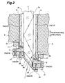
- Fig. 2 is a partly enlarged sectional view of the solid-state laser apparatus in accordance with the present invention taken along the line II-II of Fig. 1
- Fig. 3 is a perspective view of the solid-state laser medium in the solid-state laser apparatus of Fig. 1.
- 1 solid-state laser apparatus; 3a...entrance part (entrance/exit part); 3b...exit part (entrance/exit part); 3...solid-state laser medium; 5a, 5b...reflecting end face; 6a, 6b...parallel end face; 12, 12a, 12b...flow path; 13 ... inlet; 18 ... optical member; 19... heat-insulating member; 21...flow-shaping member; 23...metal mesh member (turbulence generating member); 24...holding member; 26... O-ring; L...light to be amplified; P...propagating surface.
- a solid-state laser apparatus 1 is an apparatus which amplifies light to be amplified L by propagating it in a zigzag fashion in a slab-shaped solid-state laser medium 3 arranged in a housing 2, and has a structure for cooling the solid-state laser medium 3 with a coolant.
- the laser medium 3 is one in which phosphate-based glass for laser as a matrix is doped with neodymium (Nd) as a laser active species, but is not limited thereto.
- Nd neodymium
- silica-based glass for laser or crystal materials such as YAG, YLF, YVO 4 , S-FAP, sapphire, alexandrite, forsterite, and garnet may also be used.
- the laser active species rare earth metals such as Yb, Er, Ho, and Tm or transition metals such as Cr and Ti may also be used.
- the laser medium 3 is formed like an oblong plate, whose end faces opposing each other along its longitudinal direction are an entrance end face 4a and an exit end face 4b for light to be amplified L, whereas end faces opposing each other in its thickness direction are reflecting end faces 5a, 5b of the light to be amplified L.
- the entrance end face 4a and exit end face 4b are formed oblique (with an angle of 40°, for example) with respect to the longitudinal direction of the laser medium 3, and are parallel to each other.
- propagating surface P a surface including a propagating path in which the light to be amplified L is propagated in a zigzag fashion within the laser medium 3
- end faces substantially parallel to the propagating surface P in the laser medium will be referred to as parallel end faces 6a, 6b.
- a direction substantially parallel to a line of intersection between the propagating surface P and the reflecting end face 3c i.e., the longitudinal direction of the laser medium 3 will be referred to as propagating direction.
- the laser medium 3 penetrates through the housing 2 such that the entrance end face 4a and exit end face 4b are exposed to the outside, whereas rectangular openings 2a having respective window members watertightly attached thereto are formed at respective positions opposing the reflecting end faces 5a, 5b of the laser medium 3 in the housing 2.
- semiconductor lasers 9 for irradiating the laser medium 3 with pumping light are arranged so as to extend in the propagating direction, and are held by support members 11 attached to the housing 2.
- each semiconductor laser 9 pumping light emitted from each semiconductor laser 9 is transmitted through its corresponding window member 8, so as to irradiate the laser medium 3, whereby the laser medium 3 attains an excited state. Therefore, the light to be amplified L entering the laser medium 3 from the entrance end face 4a is repeatedly totally reflected by the opposing end faces 5a, 5b while being amplified within the laser medium 3 in the excited state, so as to propagate through the laser medium 3 in a zigzag fashion and exit from the exit end face 4b.
- a flow path 12 for circulating a coolant for cooling the solid-state laser medium 3 is formed within the housing 2.
- An inlet 13 for the flow path 12 is formed at a position opposing the lower parallel end face 6a in the housing 2, whereas an upstream manifold 14 for connecting a flow path (not depicted) of a coolant feeding apparatus for supplying a coolant in a circulating fashion is attached at this position.
- an outlet 16 of the flow path 12 is formed at a position opposing the upper parallel end face 6b in the housing 2, whereas a downstream manifold 17 for connecting the flow path of the coolant feeding apparatus to the outlet 16 is attached at this position.
- the flow path 12 is split into a flow path 12a formed between one reflecting end face 5a of the laser medium 3 and one window member 8, and a flow path 12b formed between the other reflecting end face 5b and the other window member 8.
- the coolant flowing into the flow path 12 from within the upstream manifold 14 through the inlet 13 is split into the flow paths 12a and 12b, which are then combined together and flow into the downstream manifold 14 through the outlet 16.
- the coolant circulating through the flow paths 12a, 12b come into direct contact with a pair of reflecting end faces 5a, 5b of the solid-state laser medium 3, and can efficiently cool the laser medium 3 heated by the pumping light emitted from the semiconductor lasers 9. Since the coolant circulates through the flow paths 12a, 12b in a direction substantially perpendicular to the propagating surface P of the light to be amplified L, the solid-state laser medium 3 can be cooled such as to attain a uniform temperature along the propagating direction of the light to be amplified L. This can lower the thermal lens effect and thermal birefringence effect within the solid-state laser medium 3.
- an optical member 18 made of cladding glass absorbing spontaneously emitted light generated in the laser medium 3 is secured to the lower parallel end face 6a of the laser medium 3 while in a state extending in the propagating direction, whereas a heat-insulating member 19 made of Teflon (registered trademark) substantially free of deterioration caused by light is secured onto the optical member 18 while in a state extending in the propagating direction.
- an optical member 18 is secured to the upper parallel end face 6b of the laser medium 3 while in a state extending in the propagating direction, whereas a heat-insulating member 19 is secured onto the optical member 18 while in a state extending in the propagating direction.
- the spontaneously emitted light generated in the laser medium 3 upon irradiation with pumping light by the semiconductor lasers 9 is absorbed by the optical members 18, whereby the spontaneously emitted light can be prevented from being unnecessarily amplified.
- the heat-insulating members 19 prevent the heat generated in the laser medium 3 from being released from the parallel end faces 6a, 6b, whereby the temperature of the laser medium 3 can be homogenized along a direction perpendicular to the propagating surface P of the light to be amplified L as well.
- a flow-shaping member 21 having a triangular cross-sectional form widening from the inlet 13 side toward the reflecting end faces 5a, 5b is secured onto the heat-insulating member 19 while in a state extending in the propagating direction.
- the coolant can smoothly be split from the inlet 13 side toward the reflecting end faces 5a, 5b.
- a flow-shaping member 22 having a triangular cross-sectional form widening from the outlet 16 side toward the reflecting end faces 5a, 5b is secured onto the heat-insulating member 19 while in a state extending in the propagating direction.
- coolant flows can smoothly be combined together from the reflecting end faces 5a, 5b toward the outlet 16.
- a metal mesh member (turbulence generating member) 23 for turning a coolant flow into a turbulent flow is attached to the housing 2.
- the coolant comes into contact with the reflecting end faces 5a, 5b while in a turbulent state, so as to take heat away from the laser medium 3 more efficiently than in the case of a laminar state, whereby the cooling efficiency of the laser medium 3 can be improved.
- the turbulence generating member is not limited to the metal mesh member 23.
- the housing 2 may be provided with a plurality of protrusions, the flow-shaping member 21 may have a stepped surface, or the surface of the flow-shaping member 21 may be provided with a plurality of grooves extending in the propagating direction.
- corner parts to extend in the propagating direction in the entrance part (entrance/exit part) 3a where the light to be amplified L enters and the exit part (entrance/exit part) 3b where the light L exits are chamfered into curved surfaces, thus yielding an oval form (elongated racetrack form).
- Fig. 3 corner parts to extend in the propagating direction in the entrance part (entrance/exit part) 3a where the light to be amplified L enters and the exit part (entrance/exit part) 3b where the light L exits are chamfered into curved surfaces, thus yielding an oval form (elongated racetrack form).
- the entrance part 3a projects out of the housing 2, whereas a first part 24a and a second part 24b of a holding member 24 which forms a part of the side wall of the flow path 12 while holding the entrance part 3a are successively fitted into thus projected part, and an O-ring 26 is fitted to the entrance part 3a between the holding member 24 and the entrance part 3a so as to be held between the first part 24a and second part 24b.
- the first part 24a of the holding member 24 is secured to the housing 2 with a bolt 27, whereas the second part 24b is secured to the housing 2 with a bolt 28.
- the structure concerning the housing 2, holding member 24, and O-ring 26 on the exit part 3b side is the same as that on the entrance part 3 a side and thus will not be explained.
- the present invention is not limited to the above-mentioned embodiment.
- the above-mentioned embodiment relates to a case where the heat-shielding members 19 are arranged on the parallel end faces 6a, 6b by way of the optical members 18, the optical members 18 or heat-insulating members 19 may be arranged alone on the parallel end faces 6a, 6b.
- adjusting the thickness of the optical members 18 such as to regulate the amount of absorption of spontaneously emitted light can prevent the heat generated in the laser medium 3 by the heating of the optical members 18 from being released from the parallel end faces 6a, 6b even if the heat slightly escapes through the heat-insulating members 19.
- the present invention can cool a solid-state laser medium such that the solid-state laser medium attains a uniform temperature along a propagating direction of light to be amplified.
Landscapes
- Physics & Mathematics (AREA)
- Electromagnetism (AREA)
- Engineering & Computer Science (AREA)
- Plasma & Fusion (AREA)
- Optics & Photonics (AREA)
- Chemical & Material Sciences (AREA)
- Crystallography & Structural Chemistry (AREA)
- Lasers (AREA)
Abstract
A solid-state laser apparatus which can cool a solid-state laser medium such that the solid-state laser medium attains a uniform temperature along the propagating direction of light to be amplified is provided.
In a solid-state laser apparatus 1, a coolant circulating through flow paths 12a, 12b comes into direct contact with a pair of reflecting end faces 5a, 5b of a solid-state laser medium 3, whereby the laser medium 3 heated by pumping light emitted from semiconductor lasers 9 can efficiently be cooled. Since the coolant circulates through the flow paths 12a, 12b in a direction substantially perpendicular to a propagating surface P of light to be amplified L, the solid-state laser medium 3 can be cooled such as to attain a uniform temperature along a propagating direction of the light L. This can lower the thermal lens effect and thermal birefringence effect in the solid-state laser medium 3.
Description
- The present invention relates to a solid-state laser apparatus which amplifies light to be amplified by propagating it in a zigzag fashion in a slab-shaped solid-state laser medium.
- An example of conventional solid-state laser apparatus of this kind is one disclosed in Non-patent Document 1. By circulating a coolant along a propagating direction of light to be amplified so as to bring the coolant into contact with a pair of reflecting end faces reflecting the light in a laser medium, this solid-state laser apparatus prevents the laser medium from raising its temperature and reducing the thermal lens effect and thermal birefringence effect.
Non-patent Document 1: "Amplification Analysis of High-Output LD-Pumped Zigzag-Slab Nd Glass Laser", Digest of Technical Papers, the 23rd Annual Meeting of the Laser Society of Japan, p. 51 - However, the following problem exists in the above-mentioned solid-state laser apparatus. Namely, since the coolant takes heat away from the laser medium, the temperature of the coolant becomes higher on the farther downstream side, thereby generating a temperature gradient in the laser medium along the propagating direction of the light to be amplified. This keeps the thermal lens effect and thermal birefringence effect from lowering, which may cause a fear of the laser output and laser quality from decreasing.
- In view of such circumstances, it is an object of the present invention to provide a solid-state laser apparatus which can cool a solid-state laser medium such that the solid-state laser medium attains a uniform temperature along the propagating direction of light to be amplified.
- For achieving the above-mentioned object, the solid-state laser apparatus in accordance with the present invention is a solid-state laser apparatus for amplifying light to be amplified by propagating the light in a zigzag fashion in a slab-shaped solid-state laser medium, the apparatus comprising a flow path adapted to circulate a coolant in a direction substantially perpendicular to a propagating surface for the light and bring the coolant in contact with a pair of reflecting end faces for reflecting the light in the solid-state laser medium.
- In this solid-state laser apparatus, a coolant brought into contact with a pair of reflecting end faces for reflecting light to be amplified is circulated in a direction substantially perpendicular to a propagating surface for the light. Therefore, the solid-state laser medium can be cooled such as to attain a uniform temperature along a propagating direction of the light to be amplified. This can lower the thermal lens effect and thermal birefringence effect in the solid-state laser medium. Here, the propagating surface refers to a surface including a propagating path in which the light to be amplified is propagated in a zigzag fashion in the solid-state laser medium. The propagating direction refers to a direction substantially parallel to a line of intersection between the propagating surface and a reflecting end face.
- Preferably, between an inlet of the flow path and the solid-state laser medium, a flow-shaping member having a cross-sectional form widening from the inlet side toward each of the reflecting end faces is arranged. This can smoothly circulate the coolant from the inlet side toward each reflecting end face.
- Preferably, a turbulence generating member adapted to turn a coolant flow into a turbulent flow is arranged between the inlet of the flow path and the solid-state laser medium. This brings the coolant into contact with each reflecting end face in a turbulent state, so that heat can be taken away from the solid-state laser medium more efficiently than in the case of a laminar flow, thus making it possible to improve the cooling efficiency of the solid-state laser medium.
- Preferably, optical members adapted to absorb spontaneously emitted light generated in the solid-state laser medium are arranged on a pair of parallel end faces substantially parallel to the propagating surface in the solid-state laser medium. In this case, the spontaneously emitted light generated in the solid-state laser medium upon irradiation with pumping light is absorbed by the optical members arranged on the parallel end faces, whereby the spontaneously emitted light can be prevented from being amplified unnecessarily.
- Preferably, heat-insulating members are arranged on a pair of parallel end faces substantially parallel to the propagating surface in the solid-state laser medium. This prevents the heat generated in the solid-state laser medium from being released from the parallel end faces, whereby the solid-state laser medium can attain a uniform temperature along a direction perpendicular to the propagating surface of the light to be amplified as well.
- Preferably, on a pair of parallel end faces substantially parallel to the propagating surface in the solid-state laser medium, heat-insulating members are arranged by way of optical members adapted to absorb spontaneously emitted light generated in the solid-state laser medium. Employing such a structure can prevent the spontaneously emitted light generated in the solid-state laser medium from being unnecessarily amplified, and can homogenize the temperature of the solid-state laser medium along a direction perpendicular to the propagating surface of the light to be amplified as well.
- Preferably, in an entrance/exit part at each end of the solid-state laser medium where the light to be amplified enters or exits, a corner part is chamfered into a curved surface, whereas an O-ring is fitted to the entrance/exit part between a holding part forming at least a part of a side wall of the flow path while holding the entrance/exit part and the entrance/exit part. When a corner part extending in the propagating direction is chamfered into a curved surface in an entrance/exit part at each end of the solid-state laser medium, the O-ring fitted to the entrance/exit part between the holding part and entrance/exit part reliably comes into close contact with a side face of the entrance/exit part. This can reliably keep the watertightness between the holding member and the solid-state laser medium.
- The present invention can cool a solid-state laser medium such that the solid-state laser medium attains a uniform temperature along a propagating direction of light to be amplified.
- [Fig. 1]Fig. 1 is a sectional view of an embodiment of the solid-state laser apparatus in accordance with the present invention;
[Fig. 2]Fig. 2 is a partly enlarged sectional view of the solid-state laser apparatus in accordance with the present invention taken along the line II-II of Fig. 1; and
[Fig. 3]Fig. 3 is a perspective view of the solid-state laser medium in the solid-state laser apparatus of Fig. 1. - 1 ... solid-state laser apparatus; 3a...entrance part (entrance/exit part); 3b...exit part (entrance/exit part); 3...solid-state laser medium; 5a, 5b...reflecting end face; 6a, 6b...parallel end face; 12, 12a, 12b...flow path; 13 ... inlet; 18 ... optical member; 19... heat-insulating member; 21...flow-shaping member; 23...metal mesh member (turbulence generating member); 24...holding member; 26... O-ring; L...light to be amplified; P...propagating surface.
- In the following, preferred embodiments of the solid-state laser apparatus in accordance with the present invention will be explained in detail with reference to the drawings.
- As shown in Figs. 1 and 2, a solid-state laser apparatus 1 is an apparatus which amplifies light to be amplified L by propagating it in a zigzag fashion in a slab-shaped solid-
state laser medium 3 arranged in ahousing 2, and has a structure for cooling the solid-state laser medium 3 with a coolant. Thelaser medium 3 is one in which phosphate-based glass for laser as a matrix is doped with neodymium (Nd) as a laser active species, but is not limited thereto. As the matrix, silica-based glass for laser or crystal materials such as YAG, YLF, YVO4, S-FAP, sapphire, alexandrite, forsterite, and garnet may also be used. As the laser active species, rare earth metals such as Yb, Er, Ho, and Tm or transition metals such as Cr and Ti may also be used. - As shown in Fig. 3, the
laser medium 3 is formed like an oblong plate, whose end faces opposing each other along its longitudinal direction are anentrance end face 4a and anexit end face 4b for light to be amplified L, whereas end faces opposing each other in its thickness direction are reflectingend faces entrance end face 4a andexit end face 4b are formed oblique (with an angle of 40°, for example) with respect to the longitudinal direction of thelaser medium 3, and are parallel to each other. In the following explanation, a surface including a propagating path in which the light to be amplified L is propagated in a zigzag fashion within thelaser medium 3 will be referred to as propagating surface P, whereas end faces substantially parallel to the propagating surface P in the laser medium will be referred to asparallel end faces - Returning to Figs. 1 and 2, the
laser medium 3 penetrates through thehousing 2 such that theentrance end face 4a andexit end face 4b are exposed to the outside, whereasrectangular openings 2a having respective window members watertightly attached thereto are formed at respective positions opposing the reflectingend faces laser medium 3 in thehousing 2. At respective positions opposing the reflectingend faces housing 2,semiconductor lasers 9 for irradiating thelaser medium 3 with pumping light are arranged so as to extend in the propagating direction, and are held bysupport members 11 attached to thehousing 2. - As a consequence, pumping light emitted from each
semiconductor laser 9 is transmitted through itscorresponding window member 8, so as to irradiate thelaser medium 3, whereby thelaser medium 3 attains an excited state. Therefore, the light to be amplified L entering thelaser medium 3 from theentrance end face 4a is repeatedly totally reflected by theopposing end faces laser medium 3 in the excited state, so as to propagate through thelaser medium 3 in a zigzag fashion and exit from theexit end face 4b. - A
flow path 12 for circulating a coolant for cooling the solid-state laser medium 3 is formed within thehousing 2. Aninlet 13 for theflow path 12 is formed at a position opposing the lowerparallel end face 6a in thehousing 2, whereas anupstream manifold 14 for connecting a flow path (not depicted) of a coolant feeding apparatus for supplying a coolant in a circulating fashion is attached at this position. On the other hand, anoutlet 16 of theflow path 12 is formed at a position opposing the upperparallel end face 6b in thehousing 2, whereas adownstream manifold 17 for connecting the flow path of the coolant feeding apparatus to theoutlet 16 is attached at this position. - Between the
inlet 13 andoutlet 16, theflow path 12 is split into aflow path 12a formed between one reflectingend face 5a of thelaser medium 3 and onewindow member 8, and aflow path 12b formed between the other reflectingend face 5b and theother window member 8. As a consequence, the coolant flowing into theflow path 12 from within theupstream manifold 14 through theinlet 13 is split into theflow paths downstream manifold 14 through theoutlet 16. - Thus, in the solid-state laser apparatus 1, the coolant circulating through the
flow paths end faces state laser medium 3, and can efficiently cool thelaser medium 3 heated by the pumping light emitted from thesemiconductor lasers 9. Since the coolant circulates through theflow paths state laser medium 3 can be cooled such as to attain a uniform temperature along the propagating direction of the light to be amplified L. This can lower the thermal lens effect and thermal birefringence effect within the solid-state laser medium 3. - As shown in Fig. 1, an
optical member 18 made of cladding glass absorbing spontaneously emitted light generated in thelaser medium 3 is secured to the lowerparallel end face 6a of thelaser medium 3 while in a state extending in the propagating direction, whereas a heat-insulatingmember 19 made of Teflon (registered trademark) substantially free of deterioration caused by light is secured onto theoptical member 18 while in a state extending in the propagating direction. Similarly, anoptical member 18 is secured to the upperparallel end face 6b of thelaser medium 3 while in a state extending in the propagating direction, whereas a heat-insulatingmember 19 is secured onto theoptical member 18 while in a state extending in the propagating direction. - When such a structure is employed, the spontaneously emitted light generated in the
laser medium 3 upon irradiation with pumping light by thesemiconductor lasers 9 is absorbed by theoptical members 18, whereby the spontaneously emitted light can be prevented from being unnecessarily amplified. Further, the heat-insulatingmembers 19 prevent the heat generated in thelaser medium 3 from being released from theparallel end faces laser medium 3 can be homogenized along a direction perpendicular to the propagating surface P of the light to be amplified L as well. - Between the
inlet 13 of theflow path 12 and thelaser medium 3, a flow-shapingmember 21 having a triangular cross-sectional form widening from theinlet 13 side toward the reflecting end faces 5a, 5b is secured onto the heat-insulatingmember 19 while in a state extending in the propagating direction. As a consequence, the coolant can smoothly be split from theinlet 13 side toward the reflecting end faces 5a, 5b. Between theoutlet 16 of theflow path 12 and thelaser medium 3, on the other hand, a flow-shapingmember 22 having a triangular cross-sectional form widening from theoutlet 16 side toward the reflecting end faces 5a, 5b is secured onto the heat-insulatingmember 19 while in a state extending in the propagating direction. As a consequence, coolant flows can smoothly be combined together from the reflecting end faces 5a, 5b toward theoutlet 16. - Between the
inlet 13 of theflow path 12 and thelaser medium 3, a metal mesh member (turbulence generating member) 23 for turning a coolant flow into a turbulent flow is attached to thehousing 2. As a consequence, the coolant comes into contact with the reflecting end faces 5a, 5b while in a turbulent state, so as to take heat away from thelaser medium 3 more efficiently than in the case of a laminar state, whereby the cooling efficiency of thelaser medium 3 can be improved. The turbulence generating member is not limited to themetal mesh member 23. For example, thehousing 2 may be provided with a plurality of protrusions, the flow-shapingmember 21 may have a stepped surface, or the surface of the flow-shapingmember 21 may be provided with a plurality of grooves extending in the propagating direction. - Further, as shown in Fig. 3, corner parts to extend in the propagating direction in the entrance part (entrance/exit part) 3a where the light to be amplified L enters and the exit part (entrance/exit part) 3b where the light L exits are chamfered into curved surfaces, thus yielding an oval form (elongated racetrack form). As shown in Fig. 2, the
entrance part 3a projects out of thehousing 2, whereas afirst part 24a and asecond part 24b of a holdingmember 24 which forms a part of the side wall of theflow path 12 while holding theentrance part 3a are successively fitted into thus projected part, and an O-ring 26 is fitted to theentrance part 3a between the holdingmember 24 and theentrance part 3a so as to be held between thefirst part 24a andsecond part 24b. Thefirst part 24a of the holdingmember 24 is secured to thehousing 2 with abolt 27, whereas thesecond part 24b is secured to thehousing 2 with abolt 28. The structure concerning thehousing 2, holdingmember 24, and O-ring 26 on theexit part 3b side is the same as that on theentrance part 3 a side and thus will not be explained. - When such a structure is employed, fastening the
bolt 28 presses the O-ring 26 against the gap between the holdingmember 24 and theentrance part 3a. Here, since the corner parts to extend in the propagating direction in theentrance part 3a are chamfered into curved surfaces, the O-ring 26 fitted to theentrance part 3a between the holdingpart 24 and theentrance part 3a reliably comes into close contact with the side face of theentrance part 3a. The same holds on theexit part 3b side. Therefore, the watertightness between the holdingmember 24 and thelaser medium 3 can reliably be maintained. - The present invention is not limited to the above-mentioned embodiment. For example, though the above-mentioned embodiment relates to a case where the heat-shielding
members 19 are arranged on the parallel end faces 6a, 6b by way of theoptical members 18, theoptical members 18 or heat-insulatingmembers 19 may be arranged alone on the parallel end faces 6a, 6b. In the case where the heat-insulatingmembers 19 are arranged on the parallel end faces 6a, 6b by way of theoptical members 18 as in the above-mentioned embodiment, adjusting the thickness of theoptical members 18 such as to regulate the amount of absorption of spontaneously emitted light can prevent the heat generated in thelaser medium 3 by the heating of theoptical members 18 from being released from the parallel end faces 6a, 6b even if the heat slightly escapes through the heat-insulatingmembers 19. - As explained in the foregoing, the present invention can cool a solid-state laser medium such that the solid-state laser medium attains a uniform temperature along a propagating direction of light to be amplified.
Claims (7)
- A solid-state laser apparatus for amplifying light to be amplified by propagating the light in a zigzag fashion in a slab-shaped solid-state laser medium,
the apparatus comprising a flow path adapted to circulate a coolant in a direction substantially perpendicular to a propagating surface for the light and bring the coolant in contact with a pair of reflecting end faces for reflecting the light in the solid-state laser medium. - ] A solid-state laser apparatus according to claim 1, wherein, between an inlet of the flow path and the solid-state laser medium, a flow-shaping member having a cross-sectional form widening from the inlet side toward each of the reflecting end faces is arranged.
- A solid-state laser apparatus according to claim 1 or 2, wherein a turbulence generating member adapted to turn a coolant flow into a turbulent flow is arranged between the inlet of the flow path and the solid-state laser medium.
- A solid-state laser apparatus according to one of claims 1 to 3, wherein optical members adapted to absorb spontaneously emitted light generated in the solid-state laser medium are arranged on a pair of parallel end faces substantially parallel to the propagating surface in the solid-state laser medium.
- A solid-state laser apparatus according to one of claims 1 to 3, wherein heat-insulating members are arranged on a pair of parallel end faces substantially parallel to the propagating surface in the solid-state laser medium.
- A solid-state laser apparatus according to one of claims 1 to 3, wherein, on a pair of parallel end faces substantially parallel to the propagating surface in the solid-state laser medium, heat-insulating members are arranged by way of optical members adapted to absorb spontaneously emitted light generated in the solid-state laser medium.
- A solid-state laser apparatus according to one of claims 1 to 6, wherein, in an entrance/exit part at each end of the solid-state laser medium where the light to be amplified enters or exits, a corner part is chamfered into a curved surface; and
wherein an O-ring is fitted to the entrance/exit part between a holding part forming at least a part of a side wall of the flow path while holding the entrance/exit part and the entrance/exit part.
Applications Claiming Priority (2)
| Application Number | Priority Date | Filing Date | Title |
|---|---|---|---|
| JP2003333827A JP2005101324A (en) | 2003-09-25 | 2003-09-25 | Solid state laser apparatus |
| PCT/JP2004/012073 WO2005031928A1 (en) | 2003-09-25 | 2004-08-23 | Solid state laser |
Publications (2)
| Publication Number | Publication Date |
|---|---|
| EP1670103A1 true EP1670103A1 (en) | 2006-06-14 |
| EP1670103A4 EP1670103A4 (en) | 2006-10-11 |
Family
ID=34386001
Family Applications (1)
| Application Number | Title | Priority Date | Filing Date |
|---|---|---|---|
| EP04772034A Withdrawn EP1670103A4 (en) | 2003-09-25 | 2004-08-23 | Solid state laser |
Country Status (4)
| Country | Link |
|---|---|
| US (1) | US20070189346A1 (en) |
| EP (1) | EP1670103A4 (en) |
| JP (1) | JP2005101324A (en) |
| WO (1) | WO2005031928A1 (en) |
Families Citing this family (8)
| Publication number | Priority date | Publication date | Assignee | Title |
|---|---|---|---|---|
| JP2006196882A (en) * | 2004-12-14 | 2006-07-27 | Hamamatsu Photonics Kk | Optical amplifier, laser oscillator, and mopa laser equipment |
| JP5064010B2 (en) * | 2006-12-18 | 2012-10-31 | 浜松ホトニクス株式会社 | Solid state laser amplifier |
| US8218593B2 (en) * | 2008-07-24 | 2012-07-10 | Alliant Techsystems Inc. | Optical devices comprising doped glass materials, laser systems including such optical devices, and methods of forming such optical devices and laser systems |
| JP5424320B2 (en) * | 2009-08-31 | 2014-02-26 | 浜松ホトニクス株式会社 | Solid state laser equipment |
| JP6343229B2 (en) * | 2014-11-18 | 2018-06-13 | 浜松ホトニクス株式会社 | LASER AMPLIFIER, LASER DEVICE, AND LASER FUSION REACTOR |
| CN105207044A (en) * | 2015-10-12 | 2015-12-30 | 哈尔滨工业大学 | Crystal clamping frame with crystal temperature control function |
| US20230029200A1 (en) * | 2021-07-22 | 2023-01-26 | Coherent, Inc. | Actively cooled end-pumped solid-state laser gain medium |
| EP4544348A4 (en) * | 2022-06-21 | 2026-07-29 | Seurat Tech Inc | SYSTEM FOR GENERATIVE MANUFACTURING USING HOMOGENIZERS AND MOLDED REINFORCERS |
Family Cites Families (9)
| Publication number | Priority date | Publication date | Assignee | Title |
|---|---|---|---|---|
| JP2681278B2 (en) * | 1988-04-20 | 1997-11-26 | 三菱電機株式会社 | Solid-state laser device |
| JPH0322579A (en) * | 1989-06-20 | 1991-01-30 | Fuji Electric Co Ltd | Slab type solid-state laser |
| JPH0645667A (en) * | 1992-05-29 | 1994-02-18 | Hoya Corp | Solid-state laser device |
| JP3471857B2 (en) * | 1992-11-30 | 2003-12-02 | 富士電機株式会社 | Slab type solid-state laser device |
| JPH08330648A (en) * | 1995-06-05 | 1996-12-13 | Toshiba Corp | Solid state laser oscillator |
| JPH10215013A (en) * | 1997-01-30 | 1998-08-11 | Fanuc Ltd | Laser oscillation device |
| JP3154689B2 (en) * | 1998-05-26 | 2001-04-09 | 三菱重工業株式会社 | Semiconductor laser pumped slab solid-state laser device. |
| JP2001015844A (en) * | 1999-06-30 | 2001-01-19 | Saifasha:Yugen | Solid state laser device |
| JP4317722B2 (en) * | 2003-08-28 | 2009-08-19 | 浜松ホトニクス株式会社 | Solid state laser equipment |
-
2003
- 2003-09-25 JP JP2003333827A patent/JP2005101324A/en active Pending
-
2004
- 2004-08-23 EP EP04772034A patent/EP1670103A4/en not_active Withdrawn
- 2004-08-23 US US10/573,114 patent/US20070189346A1/en not_active Abandoned
- 2004-08-23 WO PCT/JP2004/012073 patent/WO2005031928A1/en not_active Ceased
Also Published As
| Publication number | Publication date |
|---|---|
| JP2005101324A (en) | 2005-04-14 |
| US20070189346A1 (en) | 2007-08-16 |
| WO2005031928A1 (en) | 2005-04-07 |
| EP1670103A4 (en) | 2006-10-11 |
Similar Documents
| Publication | Publication Date | Title |
|---|---|---|
| US6134258A (en) | Transverse-pumped sLAB laser/amplifier | |
| JP4332350B2 (en) | High-power side-pumped active mirror solid-state laser | |
| EP1371116B1 (en) | Multi-jet impingement cooled pumphead for slab laser | |
| US6167069A (en) | Thermal lens elimination by gradient-reduced zone coupling of optical beams | |
| CN101740992A (en) | Laser gain medium and laser oscillator using the same | |
| US20070189346A1 (en) | Solid-state laser apparatus | |
| EP0974177B1 (en) | Thermally improved slab laser pump cavity apparatus with integral concentrator | |
| KR101857751B1 (en) | Slab solid laser amplifier | |
| JP4317722B2 (en) | Solid state laser equipment | |
| Du et al. | YVO4/Nd: YVO4/YVO4 self-Raman laser at 1,764 nm | |
| RU2626723C2 (en) | Solid amplifier of laser radiation with diode pump with large amplification coefficient and high average power | |
| CN209544803U (en) | A kind of big energy pulse laser of compact | |
| WO2003043144A3 (en) | Diode-pumped solid-state thin slab laser | |
| JP2001203410A (en) | Zigzag slab solid-state laser amplifier and thermal lens effect compensation method for zigzag slab solid-state laser | |
| RU2753476C1 (en) | Solid-state laser light amplifier with high average power and good output beam quality | |
| JP7743043B2 (en) | High-power laser amplifier | |
| JP2003258338A (en) | Solid state laser device using slab type laser medium | |
| KR101034658B1 (en) | Optical amplifiers in the form of distributed disks | |
| JP2006196882A (en) | Optical amplifier, laser oscillator, and mopa laser equipment | |
| Yao et al. | High-power diode-pumped Nd: YAG disk laser | |
| JPH10313141A (en) | Solid laser for LD excitation | |
| JPH04336479A (en) | Slab-type solid laser device | |
| Page et al. | 1-watt composite-slab Er: YAG laser | |
| Baker et al. | High-beam-quality operation of a 150-W diode-pumped solid state planar waveguide laser | |
| JPH06310782A (en) | Slab type solid state laser device |
Legal Events
| Date | Code | Title | Description |
|---|---|---|---|
| PUAI | Public reference made under article 153(3) epc to a published international application that has entered the european phase |
Free format text: ORIGINAL CODE: 0009012 |
|
| 17P | Request for examination filed |
Effective date: 20060410 |
|
| AK | Designated contracting states |
Kind code of ref document: A1 Designated state(s): DE FR |
|
| A4 | Supplementary search report drawn up and despatched |
Effective date: 20060913 |
|
| DAX | Request for extension of the european patent (deleted) | ||
| RBV | Designated contracting states (corrected) |
Designated state(s): DE FR |
|
| 17Q | First examination report despatched |
Effective date: 20110314 |
|
| STAA | Information on the status of an ep patent application or granted ep patent |
Free format text: STATUS: THE APPLICATION IS DEEMED TO BE WITHDRAWN |
|
| 18D | Application deemed to be withdrawn |
Effective date: 20110927 |