EP1669844A2 - Remote control with touchpad and method - Google Patents
Remote control with touchpad and method Download PDFInfo
- Publication number
- EP1669844A2 EP1669844A2 EP05024588A EP05024588A EP1669844A2 EP 1669844 A2 EP1669844 A2 EP 1669844A2 EP 05024588 A EP05024588 A EP 05024588A EP 05024588 A EP05024588 A EP 05024588A EP 1669844 A2 EP1669844 A2 EP 1669844A2
- Authority
- EP
- European Patent Office
- Prior art keywords
- signal
- touchpad
- remote control
- transmitter
- instrument
- Prior art date
- Legal status (The legal status is an assumption and is not a legal conclusion. Google has not performed a legal analysis and makes no representation as to the accuracy of the status listed.)
- Withdrawn
Links
- 230000000007 visual effect Effects 0.000 claims abstract description 4
- 230000001419 dependent effect Effects 0.000 claims description 5
- 210000003811 finger Anatomy 0.000 description 13
- 230000000994 depressogenic effect Effects 0.000 description 7
- 210000003813 thumb Anatomy 0.000 description 4
- 238000010586 diagram Methods 0.000 description 2
- 239000012212 insulator Substances 0.000 description 2
- 239000002184 metal Substances 0.000 description 2
- 230000005540 biological transmission Effects 0.000 description 1
- 239000004020 conductor Substances 0.000 description 1
- 230000005684 electric field Effects 0.000 description 1
- 239000012528 membrane Substances 0.000 description 1
Images


Classifications
-
- H—ELECTRICITY
- H04—ELECTRIC COMMUNICATION TECHNIQUE
- H04B—TRANSMISSION
- H04B1/00—Details of transmission systems, not covered by a single one of groups H04B3/00 - H04B13/00; Details of transmission systems not characterised by the medium used for transmission
- H04B1/06—Receivers
- H04B1/16—Circuits
- H04B1/20—Circuits for coupling gramophone pick-up, recorder output, or microphone to receiver
- H04B1/202—Circuits for coupling gramophone pick-up, recorder output, or microphone to receiver by remote control
-
- G—PHYSICS
- G08—SIGNALLING
- G08C—TRANSMISSION SYSTEMS FOR MEASURED VALUES, CONTROL OR SIMILAR SIGNALS
- G08C17/00—Arrangements for transmitting signals characterised by the use of a wireless electrical link
- G08C17/02—Arrangements for transmitting signals characterised by the use of a wireless electrical link using a radio link
-
- G—PHYSICS
- G08—SIGNALLING
- G08C—TRANSMISSION SYSTEMS FOR MEASURED VALUES, CONTROL OR SIMILAR SIGNALS
- G08C23/00—Non-electrical signal transmission systems, e.g. optical systems
- G08C23/04—Non-electrical signal transmission systems, e.g. optical systems using light waves, e.g. infrared
-
- H—ELECTRICITY
- H03—ELECTRONIC CIRCUITRY
- H03J—TUNING RESONANT CIRCUITS; SELECTING RESONANT CIRCUITS
- H03J1/00—Details of adjusting, driving, indicating, or mechanical control arrangements for resonant circuits in general
- H03J1/0008—Details of adjusting, driving, indicating, or mechanical control arrangements for resonant circuits in general using a central processing unit, e.g. a microprocessor
- H03J1/0025—Details of adjusting, driving, indicating, or mechanical control arrangements for resonant circuits in general using a central processing unit, e.g. a microprocessor in a remote control unit
-
- H—ELECTRICITY
- H03—ELECTRONIC CIRCUITRY
- H03J—TUNING RESONANT CIRCUITS; SELECTING RESONANT CIRCUITS
- H03J2200/00—Indexing scheme relating to tuning resonant circuits and selecting resonant circuits
- H03J2200/22—Remote control device controlling cursor and/or including a cursor detecting device
-
- H—ELECTRICITY
- H03—ELECTRONIC CIRCUITRY
- H03J—TUNING RESONANT CIRCUITS; SELECTING RESONANT CIRCUITS
- H03J9/00—Remote-control of tuned circuits; Combined remote-control of tuning and other functions, e.g. brightness, amplification
Definitions
- Remote controls are well known for controlling distant equipment. Such equipment may include everything from vacuum cleaners to a television receiver.
- remote controls generally will control an on screen cursor or highlighting with direction keys that move the cursor in a pure X or Y direction. Generally, four such keys are required for left, right, up, and down cursor movement.
- a remote control comprises a touchpad that produces a signal responsive to being touched by an instrument.
- the remote control further comprises a decoder that decodes the signal and that provides a position signal indicating instrument position on the touchpad.
- the remote control further comprises a transmitter that transmits a coded signal to an external display device. The coded signal facilitates a visual indication of the instrument touchpad position by the external display device.
- FIG. 1 is a plan view of a remote control according to one embodiment of the present invention.
- FIG. 2 is a simplified block diagram of a remote control according to an embodiment of the present invention.
- FIG. 3 is a plan view illustrating the use of a remote control according to an embodiment of the present invention.
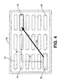
- FIG. 4 is a plan view of a display which may be controlled by the remote control of FIG. 3 according to an embodiment of the present invention.
- FIG. 1 illustrates a remote control 10 according to an embodiment of the present invention.
- the remote control 10 includes a housing 12 which houses internal circuitry of the remote control 10.
- the remote control also includes a keypad 14 including a plurality of keys 16 .
- the remote control 10 still further includes, and according to this embodiment of the invention, a touchpad 18 and selection keys 20 and 22.
- the keypad 14 is provided to function in a manner as well known in the art. Each key of the keypad 14 corresponds to a different function to be commanded of the external equipment to be controlled by the remote control 10 .
- the external equipment includes a display device for displaying menus and other selectable subject matter.
- a transmitter within the remote control 10 transmits a coded signal to the distant equipment which receives the coded signal, decodes the coded signal, and actuates the function corresponding to the key depressed.
- the transmitter of the remote control 10 may be, for example, an infra-red transmitter which utilizes an infra-red LED 24 as a transmission element.
- the touchpad 18 may be provided to the remote control 10 to enable movement of a cursor on the distant equipment display.
- the touchpad 18 may be of a type well known in the art for moving a cursor along a straight line or other line as determined by the movement of an instrument being placed on or brought into close proximity with the touchpad 18 .
- the selection keys 20 and 22 may be employed for selecting menu items which correspond to given locations on the touchpad.
- a cursor may be moved from a first position to a second position on the display screen without having to be moved in a first discreet direction and then in a second discreet direction.
- a cursor may be moved along a straight or otherwise continuous path from a first point to a second point by moving an instrument, such as a human finger, along the touchpad 18 .
- FIG. 2 shows a simplified block diagram of the remote control 10 of FIG. 1.
- the keypad 14 and touchpad 18 are coupled to a microprocessor 30 .
- the microprocessor 30 is coupled to a transmitter 32 which may be, as previously explained, an infra-red transmitter. However, as will be appreciated by those skilled in the art, the transmitter 32 may alternatively be a radio frequency (RF) transmitter.
- RF radio frequency
- the microprocessor 30 may be programmed to provide functionality of a key decoder 34 , a transmitter coder 36 , a touchpad X-Y decoder 38 . and a transmitter touchpad coder 40 .
- the key decoder 34 determines which one of the keys 16 is being depressed. Once the key decoder 34 determines which key is depressed, the transmitter coder 36 then generates a unique pulse code corresponding to the particular depressed key. The generated pulse code signal is then provided to the transmitter 32 which transmits the coded signal to the external device to be controlled.
- IR remote controls may transmit pulses of IR light to a receiver of the equipment to be controlled.
- Light emitting diodes may be utilized to transmit the IR light in a frequency range of, for example, 30 kHz - 40 Khz. These frequencies are chosen so that other light sources would not interfere with the ability to correctly receive the coded transmitted signals.
- the coded signals are transmitted in some type of binary code. The binary signal may vary in length for both time and bit length.
- This coding is usually based on varying the length of the pulses, varying the length of the spaces between the pulses, or altering the order between spaces or pulses. Accordingly, one form of code produces pulse-width-coded signals wherein the length of the pulses is varied to code the information. For example, if the pulse width is short, it corresponds to a logical 0. If, however, the pulse width is long, it corresponds to a logical 1.
- Another form of coding provides space-coded signals where the length of the spaces between the pulses is varied to code the information. In this case, if the space width is short, it may correspond to a logical 0.
- a last form of coding provides shift-coded signals where the order of the pulse space is varied to code the information.
- the signal corresponds to a logical 1.
- the signal may correspond to a logical 0.
- the coded signals are sent according to a known protocol.
- This protocol may Include, for example, information such as the address to the equipment that is using the remote and the command that the equipment must follow. The address is very important because, without it, the signal would be processed by another IR receiver in the area.
- a button on the remote When a button on the remote is pushed, it sends a string of signals.
- the first piece of information in the string is called the header.
- the header usually contains a burst of highs that alerts all of the IR receivers in the area to the string of data being sent. Following the burst of highs is the address to the specific equipment to receive the next piece of data, the command. As long as the button is held down (depressed) the command will continue to repeat over and over.
- a string of code called the stop is transmitted. As one may guess, the stop tells the equipment to stop its executing the commanded function.
- the touchpad 18 may be of the type which utilizes capacitive position sensing technology. Capacitive position sensing works by sensing an electrical phenomenon called capacitance. Whenever two electrically conductive objects come near to each other without touching, their electric fields interact to form capacitance.
- the surface of the touchpad 18 may be a grid of conductive metal wires covered by an insulator.
- the human finger is also an electrical conductor. When the finger is placed on the touchpad, a tiny capacitance forms between the finger and the metal wires in the touchpad. The insulator keeps the finger from actually touching the wires and may be textured to help the finger move smoothly across the surface of the touchpad.
- the sensing electronics may be the touchpad X-Y decoder 38 of the microprocessor 30 or alternatively, may be in an application specific integrated circuit of the touchpad 18 .
- the application specific integrated circuit or the touchpad X-Y decoder 38 may compute the position of the finger on the touchpad along with the speed in which the finger Is moving.
- the position signal thus produced by the transmitter touchpad coder 40 is thus a coded signal indicative of the position of the finger on the touchpad.
- the touchpad, touchpad X-Y decoder 38 , and the transmitter touchpad coder 40 may continuously generate position indicative signals as long as the finger or other instrument is moving across the touchpad.
- the signals thus produced are transmitted by the transmitter 32 for receipt by the distant equipment to be controlled.
- the signals may be utilized for moving a cursor on a display for performing, for example, menu selection or menu scrolling.
- a position dependent signal may be continuously produced as long as an instrument, such as a finger, is moved along the touchpad 18 . This may be utilized for moving a cursor from a first point to a second point without having to move the cursor in discrete X and Y directions.
- FIG. 3 shows a remote control 50 according to an embodiment of the present invention in use.
- the remote control includes a housing 52 , a touchpad 54 , a menu selection switch 56, and an infra-red transmitting element 58 .
- the thumb of a hand is used to swipe the touchpad 54 In the direction of an arrow 60 .
- the remote control 50 will transmit a continuously changing position dependent coded signal corresponding to, at any one time, the instantaneous position of the thumb on the touchpad 54 ;
- a display 70 includes a plurality of selectable menu options, as, for example, menu options 72 , 74 , 76 , 78 , and 80 as well as other menu options not specifically numerated.
- highlighting on the display 70 is moved from a menu option 76 directly to a menu option 78 along arrow 90 which corresponds to arrow 60 of FIG. 3.
- menu selection directly from menu option 76 to menu option 78 is rendered possible by employment of the touchpad 54 on the remote control 50 of FIG. 3. This is in direct contrast to the discrete X 92 and Y 94 cursor or highlighting of movement previously required by the prior art.
- menu option 78 When the menu option 78 Is highlighted by the thumb being over it's corresponding position on the thumb pad, the selection switch 56 may be depressed to facilitate selection of menu option 78 .
- Other menu options may be selected in a similar manner.
- touchpads have been generally described herein, other forms of touchpads may also be utilized without departing from the present invention.
- touchpads utilizing membrane switch technology or resistive sensor technology may be alternatively employed without departing from the present invention.
Landscapes
- Engineering & Computer Science (AREA)
- Computer Networks & Wireless Communication (AREA)
- Physics & Mathematics (AREA)
- General Physics & Mathematics (AREA)
- Signal Processing (AREA)
- Computer Hardware Design (AREA)
- Microelectronics & Electronic Packaging (AREA)
- Selective Calling Equipment (AREA)
- Position Input By Displaying (AREA)
Abstract
A remote control (10) facilitates the visual indication of the position of an instrument on a touchpad (18) by an external display device (70). The remote control includes a touchpad (18) that produces a signal responsive to being touched by an instrument, a decoder (38) that decodes the signal and that provides a position signal indicating instrument position on the touchpad, and a transmitter (32) that transmits a coded signal to an external display device. The coded signal facilitates a visual indication of the instrument touchpad position by the external display device.
Description
- Remote controls are well known for controlling distant equipment. Such equipment may include everything from vacuum cleaners to a television receiver.
- If the equipment to be controlled has a display for showing menus or other selectable subject matter, remote controls generally will control an on screen cursor or highlighting with direction keys that move the cursor in a pure X or Y direction. Generally, four such keys are required for left, right, up, and down cursor movement.
- While these prior art arrangements have been somewhat successful, they are cumbersome to use. Also, when time is of the essence, moving a cursor in a first direction and then in a second direction can be time consuming. Moving a cursor directly from point "A" to point "B" is impossible. The present invention addresses these issues.
- In one embodiment of the invention, a remote control comprises a touchpad that produces a signal responsive to being touched by an instrument. The remote control further comprises a decoder that decodes the signal and that provides a position signal indicating instrument position on the touchpad. The remote control further comprises a transmitter that transmits a coded signal to an external display device. The coded signal facilitates a visual indication of the instrument touchpad position by the external display device.
- FIG. 1 is a plan view of a remote control according to one embodiment of the present invention;
- FIG. 2 is a simplified block diagram of a remote control according to an embodiment of the present invention;
- FIG. 3 is a plan view illustrating the use of a remote control according to an embodiment of the present invention; and
- FIG. 4 is a plan view of a display which may be controlled by the remote control of FIG. 3 according to an embodiment of the present invention.
- In the following detailed description of exemplary embodiments of the invention, reference is made to the accompanying drawings, which form a part hereof. The detailed description and drawings illustrate a specific exemplary embodiments by which the invention may be practiced. This embodiments are described in sufficient detail to enable those skilled in the art to practice the invention. It is understood that other embodiments may be utilized, and other changes may be made, without departing from the spirit or scope of the present invention. The following detailed description Is therefore not to be taken in a limiting sense, and the scope of the present invention is defined by the appended claims.
- FIG. 1 illustrates a
remote control 10 according to an embodiment of the present invention. Theremote control 10 includes ahousing 12 which houses internal circuitry of theremote control 10. The remote control also includes akeypad 14 including a plurality ofkeys 16 . Theremote control 10 still further includes, and according to this embodiment of the invention, atouchpad 18 andselection keys - The
keypad 14 is provided to function in a manner as well known in the art. Each key of thekeypad 14 corresponds to a different function to be commanded of the external equipment to be controlled by theremote control 10 . Preferably, the external equipment includes a display device for displaying menus and other selectable subject matter. When a key of thekeypad 14 is depressed, a transmitter within theremote control 10 transmits a coded signal to the distant equipment which receives the coded signal, decodes the coded signal, and actuates the function corresponding to the key depressed. The transmitter of theremote control 10 may be, for example, an infra-red transmitter which utilizes an infra-red LED 24 as a transmission element. - The
touchpad 18 may be provided to theremote control 10 to enable movement of a cursor on the distant equipment display. Thetouchpad 18 may be of a type well known in the art for moving a cursor along a straight line or other line as determined by the movement of an instrument being placed on or brought into close proximity with thetouchpad 18. Theselection keys - By virtue of the
touchpad 18, according to this embodiment, a cursor may be moved from a first position to a second position on the display screen without having to be moved in a first discreet direction and then in a second discreet direction. Hence, a cursor may be moved along a straight or otherwise continuous path from a first point to a second point by moving an instrument, such as a human finger, along thetouchpad 18. - FIG. 2 shows a simplified block diagram of the
remote control 10 of FIG. 1. As will be noted in FIG. 2, thekeypad 14 andtouchpad 18 are coupled to amicroprocessor 30 . Themicroprocessor 30 is coupled to atransmitter 32 which may be, as previously explained, an infra-red transmitter. However, as will be appreciated by those skilled in the art, thetransmitter 32 may alternatively be a radio frequency (RF) transmitter. - The
microprocessor 30 may be programmed to provide functionality of akey decoder 34, atransmitter coder 36, atouchpad X-Y decoder 38. and atransmitter touchpad coder 40. - The
key decoder 34 determines which one of thekeys 16 is being depressed. Once thekey decoder 34 determines which key is depressed, thetransmitter coder 36 then generates a unique pulse code corresponding to the particular depressed key. The generated pulse code signal is then provided to thetransmitter 32 which transmits the coded signal to the external device to be controlled. - Infra-red (IR) signals for use with remote controls are well known. IR remote controls may transmit pulses of IR light to a receiver of the equipment to be controlled. Light emitting diodes may be utilized to transmit the IR light in a frequency range of, for example, 30 kHz - 40 Khz. These frequencies are chosen so that other light sources would not interfere with the ability to correctly receive the coded transmitted signals. The coded signals are transmitted in some type of binary code. The binary signal may vary in length for both time and bit length.
- There are generally three different ways that these signals may be coded. This coding is usually based on varying the length of the pulses, varying the length of the spaces between the pulses, or altering the order between spaces or pulses. Accordingly, one form of code produces pulse-width-coded signals wherein the length of the pulses is varied to code the information. For example, if the pulse width is short, it corresponds to a logical 0. If, however, the pulse width is long, it corresponds to a logical 1. Another form of coding provides space-coded signals where the length of the spaces between the pulses is varied to code the information. In this case, if the space width is short, it may correspond to a logical 0. However, if the space width is long, for example, it corresponds to a logical 1. A last form of coding provides shift-coded signals where the order of the pulse space is varied to code the information. In this case, if the space width is short and the pulse width is long, for example, the signal corresponds to a logical 1. However, if the space is long and the pulse is short, the signal may correspond to a logical 0.
- The coded signals are sent according to a known protocol. This protocol may Include, for example, information such as the address to the equipment that is using the remote and the command that the equipment must follow. The address is very important because, without it, the signal would be processed by another IR receiver in the area. When a button on the remote is pushed, it sends a string of signals. The first piece of information in the string is called the header. The header usually contains a burst of highs that alerts all of the IR receivers in the area to the string of data being sent. Following the burst of highs is the address to the specific equipment to receive the next piece of data, the command. As long as the button is held down (depressed) the command will continue to repeat over and over. When the button is released, a string of code called the stop is transmitted. As one may guess, the stop tells the equipment to stop its executing the commanded function.
- The
touchpad 18 may be of the type which utilizes capacitive position sensing technology. Capacitive position sensing works by sensing an electrical phenomenon called capacitance. Whenever two electrically conductive objects come near to each other without touching, their electric fields interact to form capacitance. The surface of thetouchpad 18 may be a grid of conductive metal wires covered by an insulator. The human finger is also an electrical conductor. When the finger is placed on the touchpad, a tiny capacitance forms between the finger and the metal wires in the touchpad. The insulator keeps the finger from actually touching the wires and may be textured to help the finger move smoothly across the surface of the touchpad. - Electronics, known in the art, can measure the amount of capacitance in each of the wires. When the capacitance increases, the touchpad can tell when the finger is touching it. By determining which wires have the most capacitance, the touchpad can also locate where the finger is on the touchpad to a high degree of accuracy. The sensing electronics may be the
touchpad X-Y decoder 38 of themicroprocessor 30 or alternatively, may be in an application specific integrated circuit of thetouchpad 18. The application specific integrated circuit or thetouchpad X-Y decoder 38 may compute the position of the finger on the touchpad along with the speed in which the finger Is moving. The position signal thus produced by thetransmitter touchpad coder 40 is thus a coded signal indicative of the position of the finger on the touchpad. The touchpad, touchpad X-Ydecoder 38, and thetransmitter touchpad coder 40 may continuously generate position indicative signals as long as the finger or other instrument is moving across the touchpad. The signals thus produced are transmitted by thetransmitter 32 for receipt by the distant equipment to be controlled. The signals may be utilized for moving a cursor on a display for performing, for example, menu selection or menu scrolling. - In view of the foregoing, it can be seen that a position dependent signal may be continuously produced as long as an instrument, such as a finger, is moved along the
touchpad 18. This may be utilized for moving a cursor from a first point to a second point without having to move the cursor in discrete X and Y directions. - FIG. 3 shows a
remote control 50 according to an embodiment of the present invention in use. The remote control includes ahousing 52, atouchpad 54, amenu selection switch 56, and an infra-red transmitting element 58. Here it may be seen that the thumb of a hand is used to swipe thetouchpad 54 In the direction of anarrow 60. In a manner as previously described with respect to FIG. 2, theremote control 50 will transmit a continuously changing position dependent coded signal corresponding to, at any one time, the instantaneous position of the thumb on thetouchpad 54; - As may be seen in FIG. 4, a
display 70 includes a plurality of selectable menu options, as, for example,menu options display 70 is moved from amenu option 76 directly to amenu option 78 alongarrow 90 which corresponds toarrow 60 of FIG. 3. Hence, menu selection directly frommenu option 76 tomenu option 78 is rendered possible by employment of thetouchpad 54 on theremote control 50 of FIG. 3. This is in direct contrast to the discrete X 92 andY 94 cursor or highlighting of movement previously required by the prior art. - When the
menu option 78 Is highlighted by the thumb being over it's corresponding position on the thumb pad, theselection switch 56 may be depressed to facilitate selection ofmenu option 78. Other menu options may be selected in a similar manner. - While capacitive position sensing touchpads have been generally described herein, other forms of touchpads may also be utilized without departing from the present invention. For example, touchpads utilizing membrane switch technology or resistive sensor technology, may be alternatively employed without departing from the present invention.
- Although the present invention has been described in considerable detail with reference to certain preferred embodiments, other embodiments are possible. Therefore, the spirit or scope of the appended claims should not be limited to the description of the embodiments contained therein. It is intended that the invention resides in the claims.
Claims (10)
- A remote control characterized by:a touchpad (18) that produces a signal responsive to being touched by an instrument;a decoder (38) that decodes the signal and that provides a position signal indicating instrument position on the touchpad; anda transmitter (32) that transmits a coded signal to an external display device, the coded signal facilitating a visual indication of the instrument touched position by the external display device.
- The remote control of claim 1 further characterized by the remote control including at least one key switch (20) that enables menu selection corresponding to instrument touchpad position.
- The remote control of claims 1 or 2 further characterized by the transmitter continuously transmitting the coded signal responsive to movement of the instrument across the touchpad.
- The remote control of claims 1, 2, or 3 further characterized by the decoder comprising a processor (30).
- The remote control of claims 1, 2, 3, or 4 further characterized by a coder (40) that provides the transmitter with the coded signal responsive to the position signal.
- The remote control of claim 5 further characterized by the coder comprising a processor (30).
- The remote control of claims 1, 2, 3, 4, 5, or 6 further characterized by the transmitter being an infra-red transmitter.
- The remote control of claims 1, 2, 3, 4, 5, 6, or 7 further characterized by the transmitter being a radio frequency transmitter.
- A method comprising:receiving a touchpad signal;decoding the touchpad signal to provide a position dependent signal;generating a coded position indicating signal response to the position dependent signal; andtransmitting the position indicating signal to a display device.
- The method of claim 9 further characterized by the transmitting step including continuously transmitting the position indicating signal as long as the position dependent signal is changing.
Applications Claiming Priority (1)
| Application Number | Priority Date | Filing Date | Title |
|---|---|---|---|
| US11/006,846 US20060119585A1 (en) | 2004-12-07 | 2004-12-07 | Remote control with touchpad and method |
Publications (1)
| Publication Number | Publication Date |
|---|---|
| EP1669844A2 true EP1669844A2 (en) | 2006-06-14 |
Family
ID=36118040
Family Applications (1)
| Application Number | Title | Priority Date | Filing Date |
|---|---|---|---|
| EP05024588A Withdrawn EP1669844A2 (en) | 2004-12-07 | 2005-11-10 | Remote control with touchpad and method |
Country Status (3)
| Country | Link |
|---|---|
| US (1) | US20060119585A1 (en) |
| EP (1) | EP1669844A2 (en) |
| CN (1) | CN1787030A (en) |
Cited By (2)
| Publication number | Priority date | Publication date | Assignee | Title |
|---|---|---|---|---|
| DE102009019533A1 (en) | 2009-04-30 | 2009-12-31 | Daimler Ag | Method and device for operating functions of a motor vehicle |
| CN102385467A (en) * | 2010-08-27 | 2012-03-21 | 瑞轩科技股份有限公司 | Video control method, processing method and system thereof |
Families Citing this family (64)
| Publication number | Priority date | Publication date | Assignee | Title |
|---|---|---|---|---|
| EP1727024A1 (en) * | 2005-05-27 | 2006-11-29 | Sony Ericsson Mobile Communications AB | Automatic language selection for text input in messaging context |
| KR100827150B1 (en) * | 2006-07-10 | 2008-05-02 | 삼성전자주식회사 | Apparatus for driving in portable terminal having a touch pad |
| CN100553307C (en) * | 2006-07-13 | 2009-10-21 | 义隆电子股份有限公司 | Control method using touch control panel remote controller and touch control panel remote controller used by same |
| CN101836175B (en) | 2007-09-18 | 2013-04-24 | 森赛格公司 | Method and apparatus for sensory stimulation |
| FI20085475A0 (en) * | 2008-05-19 | 2008-05-19 | Senseg Oy | Touch Device Interface |
| US20090109183A1 (en) * | 2007-10-30 | 2009-04-30 | Bose Corporation | Remote Control of a Display |
| CN201118739Y (en) | 2007-11-22 | 2008-09-17 | 深圳市同洲电子股份有限公司 | A remote controller |
| US7870496B1 (en) | 2009-01-29 | 2011-01-11 | Jahanzeb Ahmed Sherwani | System using touchscreen user interface of a mobile device to remotely control a host computer |
| US8300499B2 (en) | 2009-07-14 | 2012-10-30 | Navico, Inc. | Linear and circular downscan imaging sonar |
| US8305840B2 (en) | 2009-07-14 | 2012-11-06 | Navico, Inc. | Downscan imaging sonar |
| CN101626471B (en) * | 2009-08-13 | 2012-04-25 | 青岛海信电器股份有限公司 | Remote control device and TV set |
| US8638306B2 (en) * | 2009-11-06 | 2014-01-28 | Bose Corporation | Touch-based user interface corner conductive pad |
| US8669949B2 (en) * | 2009-11-06 | 2014-03-11 | Bose Corporation | Touch-based user interface touch sensor power |
| US20110109560A1 (en) | 2009-11-06 | 2011-05-12 | Santiago Carvajal | Audio/Visual Device Touch-Based User Interface |
| US8686957B2 (en) * | 2009-11-06 | 2014-04-01 | Bose Corporation | Touch-based user interface conductive rings |
| US8692815B2 (en) * | 2009-11-06 | 2014-04-08 | Bose Corporation | Touch-based user interface user selection accuracy enhancement |
| US20110113368A1 (en) * | 2009-11-06 | 2011-05-12 | Santiago Carvajal | Audio/Visual Device Graphical User Interface |
| US9354726B2 (en) * | 2009-11-06 | 2016-05-31 | Bose Corporation | Audio/visual device graphical user interface submenu |
| US20110113371A1 (en) * | 2009-11-06 | 2011-05-12 | Robert Preston Parker | Touch-Based User Interface User Error Handling |
| US8601394B2 (en) * | 2009-11-06 | 2013-12-03 | Bose Corporation | Graphical user interface user customization |
| US9201584B2 (en) | 2009-11-06 | 2015-12-01 | Bose Corporation | Audio/visual device user interface with tactile feedback |
| USD687843S1 (en) | 2009-11-06 | 2013-08-13 | Bose Corporation | Audio/video device with graphical user interface |
| US8350820B2 (en) * | 2009-11-06 | 2013-01-08 | Bose Corporation | Touch-based user interface user operation accuracy enhancement |
| US8326333B2 (en) * | 2009-11-11 | 2012-12-04 | Sony Ericsson Mobile Communications Ab | Electronic device and method of controlling the electronic device |
| US8766933B2 (en) | 2009-11-12 | 2014-07-01 | Senseg Ltd. | Tactile stimulation apparatus having a composite section comprising a semiconducting material |
| US9595186B2 (en) | 2010-01-04 | 2017-03-14 | Samsung Electronics Co., Ltd. | Electronic device combining functions of touch screen and remote control and operation control method thereof |
| US8860676B2 (en) * | 2010-01-26 | 2014-10-14 | Panasonic Intellectual Property Corporation Of America | Display control device, method, program, and integrated circuit |
| CN101820515A (en) * | 2010-03-23 | 2010-09-01 | 青岛海信电器股份有限公司 | Human-computer interaction method, television terminal and remote control |
| CN101854496A (en) * | 2010-04-28 | 2010-10-06 | 青岛海信电器股份有限公司 | Television set and control method and remote controller thereof |
| CN102280020B (en) * | 2010-06-11 | 2013-02-13 | 幻音科技(深圳)有限公司 | Touch type remote controller |
| CN101964139A (en) * | 2010-08-20 | 2011-02-02 | 江苏惠通集团有限责任公司 | Laser navigation remote-control unit |
| CN101916502A (en) * | 2010-08-20 | 2010-12-15 | 江苏惠通集团有限责任公司 | Touch remote controller |
| CN103430519B (en) * | 2011-01-18 | 2015-12-02 | 萨万特系统有限责任公司 | The RCI of new line operation and visual feedback is provided |
| US9142206B2 (en) | 2011-07-14 | 2015-09-22 | Navico Holding As | System for interchangeable mounting options for a sonar transducer |
| US9182486B2 (en) | 2011-12-07 | 2015-11-10 | Navico Holding As | Sonar rendering systems and associated methods |
| US9268020B2 (en) | 2012-02-10 | 2016-02-23 | Navico Holding As | Sonar assembly for reduced interference |
| US9348028B2 (en) | 2012-07-06 | 2016-05-24 | Navico Holding As | Sonar module using multiple receiving elements |
| US9354312B2 (en) | 2012-07-06 | 2016-05-31 | Navico Holding As | Sonar system using frequency bursts |
| US9495065B2 (en) | 2012-07-06 | 2016-11-15 | Navico Holding As | Cursor assist mode |
| US9442636B2 (en) | 2012-07-06 | 2016-09-13 | Navico Holding As | Quick split mode |
| US9846038B2 (en) | 2012-07-06 | 2017-12-19 | Navico Holding As | Export user data from defined region |
| US9361693B2 (en) | 2012-07-06 | 2016-06-07 | Navico Holding As | Adjusting parameters of marine electronics data |
| US9298079B2 (en) | 2012-07-06 | 2016-03-29 | Navico Holding As | Sonar preview mode |
| US9182239B2 (en) | 2012-11-06 | 2015-11-10 | Navico Holding As | Displaying laylines |
| US9122366B2 (en) | 2013-03-15 | 2015-09-01 | Navico Holding As | Residue indicators |
| US9909891B2 (en) | 2013-08-14 | 2018-03-06 | Navico Holding As | Display of routes to be travelled by a marine vessel |
| US10251382B2 (en) | 2013-08-21 | 2019-04-09 | Navico Holding As | Wearable device for fishing |
| US9507562B2 (en) | 2013-08-21 | 2016-11-29 | Navico Holding As | Using voice recognition for recording events |
| US10481259B2 (en) | 2013-09-13 | 2019-11-19 | Navico Holding As | Tracking targets on a sonar image |
| US10290124B2 (en) | 2013-10-09 | 2019-05-14 | Navico Holding As | Sonar depth display |
| CN103927864B (en) * | 2014-03-28 | 2017-10-20 | 小米科技有限责任公司 | Infrared signal sending method, device and remote control |
| US9720084B2 (en) | 2014-07-14 | 2017-08-01 | Navico Holding As | Depth display using sonar data |
| US9267804B1 (en) | 2014-09-24 | 2016-02-23 | Navico Holding As | Forward depth display |
| US9836129B2 (en) | 2015-08-06 | 2017-12-05 | Navico Holding As | Using motion sensing for controlling a display |
| US9781468B2 (en) | 2015-08-25 | 2017-10-03 | Echostar Technologies L.L.C. | Dynamic scaling of touchpad/UI grid size relationship within a user interface |
| US9826187B2 (en) | 2015-08-25 | 2017-11-21 | Echostar Technologies L.L.C. | Combined absolute/relative touchpad navigation |
| US10151829B2 (en) | 2016-02-23 | 2018-12-11 | Navico Holding As | Systems and associated methods for producing sonar image overlay |
| USD788049S1 (en) * | 2016-05-27 | 2017-05-30 | Hung Hsing Electric Co., Ltd. | Remote control for air purifiers |
| DK201670574A1 (en) * | 2016-06-12 | 2018-01-02 | Apple Inc | Accelerated scrolling |
| US10460484B2 (en) | 2016-06-24 | 2019-10-29 | Navico Holding As | Systems and associated methods for route generation and modification |
| US10948577B2 (en) | 2016-08-25 | 2021-03-16 | Navico Holding As | Systems and associated methods for generating a fish activity report based on aggregated marine data |
| US11367425B2 (en) | 2017-09-21 | 2022-06-21 | Navico Holding As | Sonar transducer with multiple mounting options |
| JP7019489B2 (en) * | 2018-03-30 | 2022-02-15 | 住友重機械工業株式会社 | Injection molding machine |
| US12007512B2 (en) | 2020-11-30 | 2024-06-11 | Navico, Inc. | Sonar display features |
Family Cites Families (8)
| Publication number | Priority date | Publication date | Assignee | Title |
|---|---|---|---|---|
| US4413260A (en) * | 1981-08-31 | 1983-11-01 | Stern Electronics, Inc. | Remote-control system for coin-operated phonographs |
| US5973757A (en) * | 1997-03-31 | 1999-10-26 | Aubuchon; Mark S. | Contoured and balanced remote tv control device |
| US6429846B2 (en) * | 1998-06-23 | 2002-08-06 | Immersion Corporation | Haptic feedback for touchpads and other touch controls |
| US6765557B1 (en) * | 2000-04-10 | 2004-07-20 | Interlink Electronics, Inc. | Remote control having touch pad to screen mapping |
| EP1276237A1 (en) * | 2001-07-12 | 2003-01-15 | Sony Corporation | Remote controller and system having the same |
| KR100811339B1 (en) * | 2001-10-11 | 2008-03-07 | 엘지전자 주식회사 | Remote control system and method for implementing a graphical user interface |
| US20050151727A1 (en) * | 2004-01-08 | 2005-07-14 | Intel Corporation | Wireless enabled touch pad pointing device with integrated remote control function |
| US20050160451A1 (en) * | 2004-01-16 | 2005-07-21 | Mitsubishi Digital Electronics America, Inc. | Home message system |
-
2004
- 2004-12-07 US US11/006,846 patent/US20060119585A1/en not_active Abandoned
-
2005
- 2005-11-10 EP EP05024588A patent/EP1669844A2/en not_active Withdrawn
- 2005-12-07 CN CN200510131090.9A patent/CN1787030A/en active Pending
Cited By (3)
| Publication number | Priority date | Publication date | Assignee | Title |
|---|---|---|---|---|
| DE102009019533A1 (en) | 2009-04-30 | 2009-12-31 | Daimler Ag | Method and device for operating functions of a motor vehicle |
| CN102385467A (en) * | 2010-08-27 | 2012-03-21 | 瑞轩科技股份有限公司 | Video control method, processing method and system thereof |
| CN102385467B (en) * | 2010-08-27 | 2013-11-06 | 瑞轩科技股份有限公司 | Video control method, processing method and system thereof |
Also Published As
| Publication number | Publication date |
|---|---|
| CN1787030A (en) | 2006-06-14 |
| US20060119585A1 (en) | 2006-06-08 |
Similar Documents
| Publication | Publication Date | Title |
|---|---|---|
| EP1669844A2 (en) | Remote control with touchpad and method | |
| US7088342B2 (en) | Input method and input device | |
| US6529189B1 (en) | Touch screen stylus with IR-coupled selection buttons | |
| US5144594A (en) | Acoustic mouse system | |
| KR100786429B1 (en) | Wireless input apparatus and method using a three-dimensional pointing device | |
| US10073558B2 (en) | Position indicator, position detecting device, and input control method of position detecting device | |
| KR100782431B1 (en) | Multipoint Coordinate Recognition Method and Contact Area Recognition Method of Infrared Touch Screen | |
| US6335723B1 (en) | Transmitter pen location system | |
| US6414673B1 (en) | Transmitter pen location system | |
| US8316324B2 (en) | Method and apparatus for touchless control of a device | |
| US6947062B2 (en) | Seamlessly combined freely moving cursor and jumping highlights navigation | |
| US5707160A (en) | Infrared based computer input devices including keyboards and touch pads | |
| CN1728065B (en) | Position detection device and input system | |
| EP0609819A1 (en) | Mouse and method for concurrent cursor position and scrolling control | |
| US11221688B2 (en) | Input apparatus with relation between pen and finger touches | |
| EP3051390B1 (en) | Rotational element enabling touch-like gestures | |
| US20160018911A1 (en) | Touch pen | |
| EP3667473B1 (en) | System and method for multi-mode command input | |
| JP2005293606A (en) | Touch input detection method and touch input detection device | |
| EP2320304A2 (en) | Apparatus and method for motion recognition | |
| GB2321328A (en) | Transmitting and receiving remote controller pointing data | |
| KR100699670B1 (en) | Display system using remote input device | |
| JPH06214712A (en) | Information input device | |
| JPH0553719A (en) | Coordinate input device | |
| KR970022691A (en) | Information input device and receiving device |
Legal Events
| Date | Code | Title | Description |
|---|---|---|---|
| PUAI | Public reference made under article 153(3) epc to a published international application that has entered the european phase |
Free format text: ORIGINAL CODE: 0009012 |
|
| AK | Designated contracting states |
Kind code of ref document: A2 Designated state(s): AT BE BG CH CY CZ DE DK EE ES FI FR GB GR HU IE IS IT LI LT LU LV MC NL PL PT RO SE SI SK TR |
|
| AX | Request for extension of the european patent |
Extension state: AL BA HR MK YU |
|
| STAA | Information on the status of an ep patent application or granted ep patent |
Free format text: STATUS: THE APPLICATION IS DEEMED TO BE WITHDRAWN |
|
| 18D | Application deemed to be withdrawn |
Effective date: 20130601 |