EP1669770A1 - Magneto-optical sensors - Google Patents
Magneto-optical sensors Download PDFInfo
- Publication number
- EP1669770A1 EP1669770A1 EP05257283A EP05257283A EP1669770A1 EP 1669770 A1 EP1669770 A1 EP 1669770A1 EP 05257283 A EP05257283 A EP 05257283A EP 05257283 A EP05257283 A EP 05257283A EP 1669770 A1 EP1669770 A1 EP 1669770A1
- Authority
- EP
- European Patent Office
- Prior art keywords
- optical
- loop
- magneto
- current
- resonator
- Prior art date
- Legal status (The legal status is an assumption and is not a legal conclusion. Google has not performed a legal analysis and makes no representation as to the accuracy of the status listed.)
- Ceased
Links
- 230000003287 optical effect Effects 0.000 claims abstract description 40
- 239000004020 conductor Substances 0.000 claims description 24
- 239000013307 optical fiber Substances 0.000 claims description 15
- 230000001902 propagating effect Effects 0.000 claims description 12
- 230000008859 change Effects 0.000 claims description 7
- 239000013078 crystal Substances 0.000 claims description 3
- 230000010363 phase shift Effects 0.000 description 11
- 230000005540 biological transmission Effects 0.000 description 8
- 238000000034 method Methods 0.000 description 7
- 230000004044 response Effects 0.000 description 7
- 238000005259 measurement Methods 0.000 description 6
- 230000003595 spectral effect Effects 0.000 description 6
- 230000008878 coupling Effects 0.000 description 5
- 238000010168 coupling process Methods 0.000 description 5
- 238000005859 coupling reaction Methods 0.000 description 5
- 230000000694 effects Effects 0.000 description 5
- 239000000835 fiber Substances 0.000 description 5
- 239000000463 material Substances 0.000 description 5
- 230000010287 polarization Effects 0.000 description 5
- 238000001514 detection method Methods 0.000 description 4
- 239000011521 glass Substances 0.000 description 4
- 238000009413 insulation Methods 0.000 description 3
- 238000012544 monitoring process Methods 0.000 description 3
- 229910052691 Erbium Inorganic materials 0.000 description 2
- 229910052771 Terbium Inorganic materials 0.000 description 2
- 229910052769 Ytterbium Inorganic materials 0.000 description 2
- 230000002950 deficient Effects 0.000 description 2
- UYAHIZSMUZPPFV-UHFFFAOYSA-N erbium Chemical compound [Er] UYAHIZSMUZPPFV-UHFFFAOYSA-N 0.000 description 2
- 238000001228 spectrum Methods 0.000 description 2
- GZCRRIHWUXGPOV-UHFFFAOYSA-N terbium atom Chemical compound [Tb] GZCRRIHWUXGPOV-UHFFFAOYSA-N 0.000 description 2
- NAWDYIZEMPQZHO-UHFFFAOYSA-N ytterbium Chemical compound [Yb] NAWDYIZEMPQZHO-UHFFFAOYSA-N 0.000 description 2
- GYHNNYVSQQEPJS-UHFFFAOYSA-N Gallium Chemical compound [Ga] GYHNNYVSQQEPJS-UHFFFAOYSA-N 0.000 description 1
- 229910003327 LiNbO3 Inorganic materials 0.000 description 1
- 238000005452 bending Methods 0.000 description 1
- 230000009977 dual effect Effects 0.000 description 1
- 230000007613 environmental effect Effects 0.000 description 1
- 230000004907 flux Effects 0.000 description 1
- 229910052733 gallium Inorganic materials 0.000 description 1
- 239000002223 garnet Substances 0.000 description 1
- 239000000382 optic material Substances 0.000 description 1
- 230000001151 other effect Effects 0.000 description 1
- 230000035699 permeability Effects 0.000 description 1
- 229920000642 polymer Polymers 0.000 description 1
- 238000010248 power generation Methods 0.000 description 1
- 229910052761 rare earth metal Inorganic materials 0.000 description 1
- 239000004065 semiconductor Substances 0.000 description 1
- 238000010408 sweeping Methods 0.000 description 1
Images





Classifications
-
- G—PHYSICS
- G01—MEASURING; TESTING
- G01R—MEASURING ELECTRIC VARIABLES; MEASURING MAGNETIC VARIABLES
- G01R33/00—Arrangements or instruments for measuring magnetic variables
- G01R33/02—Measuring direction or magnitude of magnetic fields or magnetic flux
- G01R33/032—Measuring direction or magnitude of magnetic fields or magnetic flux using magneto-optic devices, e.g. Faraday or Cotton-Mouton effect
-
- G—PHYSICS
- G01—MEASURING; TESTING
- G01R—MEASURING ELECTRIC VARIABLES; MEASURING MAGNETIC VARIABLES
- G01R15/00—Details of measuring arrangements of the types provided for in groups G01R17/00 - G01R29/00, G01R33/00 - G01R33/26 or G01R35/00
- G01R15/14—Adaptations providing voltage or current isolation, e.g. for high-voltage or high-current networks
- G01R15/24—Adaptations providing voltage or current isolation, e.g. for high-voltage or high-current networks using light-modulating devices
- G01R15/245—Adaptations providing voltage or current isolation, e.g. for high-voltage or high-current networks using light-modulating devices using magneto-optical modulators, e.g. based on the Faraday or Cotton-Mouton effect
Definitions
- the invention relates generally to sensors.
- the invention particularly relates to magneto-optical current and magnetic field sensors.
- Measurement of currents flowing in high-voltage environments is also highly desirable, especially in power transmission and distribution systems.
- Transmission and distribution systems react dynamically to changes in active and reactive power.
- reactive compensation systems are desirable, particularly systems capable of simultaneously monitoring current flow at several points on a grid.
- a system for current or magnetic field parameter determination comprises a resonant frequency tunable magneto-optical loop resonator, wherein the loop resonator comprises a magneto-optical sensing element coupled to an optical waveguide, and wherein the loop resonator is configured for receiving an originating optical signal, propagating the signal in two counter directions, and providing a modulated signal indicative of the parameter.
- a system for current or magnetic field parameter determination comprises a plurality of resonant frequency tunable magneto-optical loop resonators, wherein each loop resonator comprises a magneto-optical sensing element coupled to an optical waveguide, and wherein the loop resonators are configured for receiving an optical signal, propagating the signal in two counter directions, and providing a modulated signal indicative of the parameter.
- a method for current or magnetic field parameter determination comprises providing at least one frequency tunable magneto-optical loop resonator, positioning the loop resonator in a magnetic field to be sensed, coupling an originating signal from a source into the at least one loop resonator, propagating the originating signal through two arms of the loop resonator and detecting a modulated signal from the at least one resonator.
- adapted to refers to devices in a system to allow the elements of the system to cooperate to provide a described effect; these terms also refer to operation capabilities of electrical or optical elements such as analog or digital computers or application specific devices (such as an application specific integrated circuit (ASIC)), amplifiers or the like that are programmed to provide an output in response to given input signals, and to mechanical devices for optically or electrically coupling components together.
- ASIC application specific integrated circuit
- current can refer to either alternating current (AC) or direct current (DC).
- Embodiments of the present invention relate to magneto optical sensors for estimating a parameter selected from the group consisting of a current, a magnetic field, or combinations thereof.
- a resonant frequency tunable magneto-optical loop resonator 10 is configured to receive an originating optical signal and to counter propagate the signal through the resonator.
- the loop resonator comprises a magneto-optical sensing element 12 coupled to a waveguide 14 to form a resonator structure.
- the waveguide may comprise either a guided waveguide or a free-space beam.
- Light splitter 16 which may comprises a beam splitter, fiber, or waveguide directional coupler, for example, separates the incoming light into the two counter-propagating arms of the loop resonator.
- the loop resonator 10 is further configured to send a recombined signal or modulated signal out of the loop resonator into a transmitted port (shown as optical fiber 24) and reflected port (shown as optical fiber 22).
- Faraday rotation is the rotation of polarization of light by a magneto-optic material due to the presence of a magnetic field parallel to the direction of propagation of light.
- Faraday effect induced non-reciprocal phase shift or non-reciprocal refractive index shift is a change in the velocity of propagation in the presence of a magnetic field parallel to the direction of propagation of light. This change reverses sign if either the field or the propagation direction is reversed.
- the non-reciprocal phase shift is proportional to the Faraday rotation or the Verdet constant of the material.
- V is the Verdet constant of magneto-optical sensing element material and I the current flowing through the conductor along a unit length dl.
- the resonant frequency f of a loop resonator is a function of the refractive index n of the resonator material and the length L1 of the loop resonator.
- the resonance frequency of the loop resonator will be a sensitive function of the non-reciprocal phase changes experienced by the two counter-propagating light waves in the loop.
- the resonant frequency of the resonator (or wavelength) is obtained by the frequency filtered by the resonator and can give a precise estimation of the applied magnetic field.
- the non-reciprocal index change within the resonator results in a frequency shift ⁇ f of the resonant frequency.
- I ⁇ f ⁇ 2 ⁇ n L 1 / ( c N V ) .
- Obtaining the frequency of the resonator or the frequency filtered by the resonator can provide a precise estimation of the applied magnetic field.
- the current carried through the conductor can then be estimated. All other effects such as stress and temperature are reciprocal in regards to the counter-propagating light inside the loop, such that the relative phase noises cancel each when the two waves combine at the light splitter 16.
- a non-limiting example of the magneto-optical sensing element 12 includes a coiled optical fiber element.
- the optical fiber coil may be looped around the current carrying conductor in several turns to sense the magnetic field.
- the sensing element comprises an erbium or ytterbium doped multiple-turn coiled optical fiber element.
- the number of turns in a multiple-turn coiled optical fiber element coil is about 200.
- Non-limiting examples of optical waveguides 14 include optical fibers, waveguide structures including glass, polymer waveguide structures, semiconductor material waveguide structures or period of free-space connection structures. Loop resonators with optical waveguides of different geometries, different mode structures and varying refractive index distribution are within the scope of this invention
- An optical source 20 is configured for sending an originating optical signal that is coupled into at least one magneto-optical loop resonator 10 through an optical fiber 22.
- a non-limiting example of an optical source 20 includes a broadband source.
- a broadband source is defined as a source or collection of sources capable of emitting light over a range of wavelengths.
- the broadband source may comprise a single wavelength tunable laser or a multi-wavelength broadband laser, for example.
- At least one light splitter 16 is used to couple the originating signal into the loop resonator and the modulated signal out of the loop resonator.
- a processor 30 is configured for receiving the modulated signal from the magneto-optical loop resonator 10 through an optical fiber 24.
- the processor also functions as a wavelength demultiplexer to resolve the resonance responses from each sensor.
- the processor may include one or more wavelength de-multiplexing elements, optical spectral meters, wavelength meters, photodetectors, differential amplifiers, and analog to digital converters.
- the wavelength demultiplexing element may comprise an array waveguide grating, a transmission or a deflection grating with a detection circuit tunable device such as a Fabry Perot interferometer, a ring resonator or a filter, for example.
- the processor 40 and the optical source 30 are integrated into a single unit to form an optical interrogator module 50.
- part of the originating signal is sent to the processor as a reference signal to help extract a substantially accurate parameter value.
- the magneto-optical loop resonator 10 is coupled to at least one ring filter 18.
- This enables the adjustment of a wide range of parameters such as Free Spectral Ranges (FSR), Full Width Half Maximum (FWHM) and filter finesse.
- the ring filter can be used as a reference for temperature compensation of the loop resonator.
- Non-limiting examples of a ring filter include a loop resonator and a ring resonator. By choosing a desired coupling ratio, the frequency characteristics of the loop resonator ⁇ ring filter combination can be configured.
- a magneto-optical loop resonator with a 200-turn optical fiber sensing element is coupled to a resonator filter, wherein the difference in resonator lengths ⁇ L is in the range of about 0.01 mm to about 0.1mm.
- a lower ⁇ L value results in higher frequency resolution and higher accuracy in the estimated current.
- Such a system would typically exhibit a sub-nanometer resolution and could, for example, estimate a 3000 ampere current flowing through a conductor with an accuracy of 1% or better.
- the magneto-optical sensing head 12 is a magneto-optical crystal 12 with a desirable Verdet constant.
- magneto-optical crystals include terbium gallium garnet (TGG), terbium doped borosillicate glass, rare earth ion, erbium doped glass, ytterbium doped glass or LiNbO3.
- each system may include one or more of such elements and "a" as used herein is intended to mean "at least one.”
- the output signal from one loop resonator may be coupled into the input of a second loop resonator.
- a system in accordance with an embodiment of the present invention has at least two of the magneto optical loop resonators having different resonant frequencies. In a second example, the system has at least two resonators with the same resonant frequency.
- One embodiment of the present invention where a plurality of magneto-optical loop resonators is used is a distributed current estimation system as shown in FIG 4.
- the sensors are used in a distributed architecture with magneto optical loop resonators 10 with different resonant frequencies being located in multiple locations to sense current flowing through different conductors 40.
- An originating signal from a broadband source 20 is coupled into the input of a first loop resonator 10.
- the modulated signal from the final resonator is input into the processor.
- the sensors can be cascaded and can be remotely distinguished by their different resonant frequency.
- the distributed current estimation system is embodied in a power substation.
- power distribution to multiple transmission lines typically occurs in a power substation.
- a power station includes a distributed current estimation system to monitor current flow in multiple transmission lines.
- the distributed current estimation system is embodied in a power monitoring system in a transportation system.
- a transportation system wherein electrical power generation and distribution occurs within the transportation system, includes a power monitoring system comprising a distributed current estimation system for sensing current .
- An embodiment of the present invention where a plurality of magneto-optical loop resonators are used, is a differential current estimation system as shown in Fig. 5. It is desirable to have a system to estimate the difference between current flowing at two points along the same conductor. Such measurements may be used for differential fault current relaying in electric power systems.
- Difference in current can also provide information about the condition of the insulation surrounding the conductor. For example, small leakage currents to ground, through defective insulation at one point along a conductor, will typically lead to unequal currents being estimated at two points on either side of the defective insulation.
- the system is capable of obtaining the differential signal between current flowing at two points along the same conductor.
- At least two magneto-optical loop resonator sensors 10 are placed in the field of a current carrying conductor 40 at different points along the same conductor.
- the optical signal from an optical source 20 is coupled into each loop resonator and the modulated optical signal from each loop resonator is detected and processed by a processor 30 to extract the difference current between two points in a conductor.
- a ground fault detection system comprises two or more magneto-optical sensors configured to measure current in two or more conductors or power lines to measure unbalanced load in the conductors or power lines.
- a ground fault detection system can be implemented in a three-phase AC system with a balanced load, to detect any imbalance in the system and is within the scope of this invention.
- FIG 6 In an illustrated embodiment in accordance with the present invention as shown in FIG 6 is a reactive compensation system for power transmission and distribution (T&D) networks.
- T&D power transmission and distribution
- several magneto-optical loop resonators 10 with magneto-optic sensing elements 12 completely isolated from ground potential are mounted at several points on conductors in a transmission network 60.
- Each loop resonator may further be coupled to at least one ring filter 18.
- the optical interrogator module 50 interrogates the sensors by sending an originating broadband signal along at least one optical fiber 22.
- Each loop resonator sensor 10 is configured to respond in different wavelength regions. The loop resonator sensor responds to changes in current causing the filtered frequency to change.
- the optical interrogator module 50 receives the resulting modulated optical signal.
- the optical signal originating from different magneto-optical sensors is demultiplexed by demultiplexers, and converted to electric signals by photodetectors housed in the optical interrogator module 50.
- the signal is further processed and the information on current flow at various points on the network is passed on to a controller to enable dynamic control of the power flow in the system.
- a method for estimating a parameter selected from the group consisting of a current, a magnetic field, or combinations thereof comprises the steps of providing at least one frequency tunable magneto-optical loop resonator with a sensing element, positioning the sensing element in a magnetic field to be sensed, coupling an originating signal from a source into the at least one loop resonator; propagating the originating signal along two counter propagating directions through two arms of the loop resonator and detecting a modulated signal from the at least one resonator.
- the method further includes providing a processor for determining the value of the parameter.
- the method further includes configuring the processor for difference current estimation.
- a method for estimating a parameter selected from the group consisting of a current, a magnetic field, or combinations thereof includes configuring multiple resonators with different resonant frequencies and positioning them in the magnetic field of different conductors to form a distributed network, sending an originating signal through the multiple loop resonators, configuring the processor for demultiplexing the received modulated signal and estimating the parameter.
- a time division-multiplexing scheme is used.
- modulated signals from the magneto-optical sensors are resolved by observing the signals at different times.
- the magneto-optical sensors are connected at different fiber lengths to the source and or the processor, the time of arrival of modulated signals will be different for each sensor.
- FIG. 7 A non-limiting example is illustrated in FIG. 7.
- Two resonators 210 and 310 each with different loop length L1 and L2, are coupled with a 99:1 coupler 116.
- An input coupler 216 in resonator 210 is 50:50 and an output coupler 316 in resonator 310 is 98:2.
- the coupling ratios in the couplers are chosen to optimize the spectral responses per as shown in FIGs. 8 and 9 (graphs illustrating an expected spectral response of the double ring system for the example of FIG. 7) with the solid line representing the system at room temperature and the dashed line representing the system at a temperature of about 200 degrees Celsius above room temperature.
- the temperature induced wavelength shift is estimated to be less than about 1 GHz (0.008nm) over a 200 degree Celsius span.
- a system in accordance with one embodiment of the present invention was used to measure a current flowing though a conductor sourced from an Agilent DC power source with variable current output.
- the current output by the source was variable from 0 Amperes to 700 Amperes.
- a magneto-optical loop resonator with a sensing element comprising a 120-turn optical fiber coil wrapped around the conductor was used to sense the current flowing through the conductor.
- a laser diode lasing in the region of about 1545 nm was used as an optical source, and the output used to interrogate the loop resonator.
- An interrogation system comprising a sweep meter was used to estimate the current.
- a sweep meter for example from Precision Photonics, is typically used for sweeping the laser diode output wavelength.
- a wavelength monitor was used to monitor the wavelength.
- the resonance frequency of the loop resonator exhibited a wavelength shift of about 1.3 nm (1546 nm to 1547.3 nm) for a non-reciprocal phase shift of about .16 ⁇ .
- the wavelength shifts were converted to corresponding amplitude shifts using a wavelength filter around the center wavelength, and the current estimated by measuring the amplitudes is shown in FIG. 12. The response is linear within the current measurement range.
- the potential for multiplexing more wavelength length channels is high due to the over-all available spectrum of 50 nm (from 1520 nanometer to 1570 nanometer), and the demonstrated channel occupying a width of 1.4 nm, as shown in FIG. 13.
- the previously described embodiments of the present invention have many advantages, including eliminating polarization components, which consist of one third of the measurement setup being used in the polarimetric current sensors, hence increasing robustness against the environmental noises such as fiber bending and material stress. Sensing in the optical wavelength (frequency) domain allows linear, scalable and precision estimation for a high dynamic range without suffering saturation effects.
- the system for estimating current of the present invention desirably has a linear response over a large dynamic range.
Landscapes
- Physics & Mathematics (AREA)
- Engineering & Computer Science (AREA)
- Power Engineering (AREA)
- General Physics & Mathematics (AREA)
- Condensed Matter Physics & Semiconductors (AREA)
- Measuring Instrument Details And Bridges, And Automatic Balancing Devices (AREA)
- Measuring Magnetic Variables (AREA)
Abstract
Description
- The invention relates generally to sensors. The invention particularly relates to magneto-optical current and magnetic field sensors.
- Conventional transformer-based current sensors are large in size for field operations and tend to saturate at high voltages or currents. Alternative current sensors, such as optical current sensors, typically rely upon the Faraday effect of the magnetic field created by the current to alter the polarization of light propagating in a fiber near the conductor. The method for extracting this information from the fiber is very intricate and costly. In one example, complex active power supplies are located at line potential. Fiber-optic current sensors based on polarimetric methods require stringent control on the polarization state. The components for polarization measurement are usually based on costly bulk optical components and maintaining the alignment through a number of these types of components becomes a challenging task. Furthermore, cascading polarimetric current sensors for distributed sensing applications may not be practical due to system complexity.
- Measurement of currents flowing in high-voltage environments is also highly desirable, especially in power transmission and distribution systems. Transmission and distribution systems react dynamically to changes in active and reactive power. For power transmission to be economical and the risk of power system failure to be low, reactive compensation systems are desirable, particularly systems capable of simultaneously monitoring current flow at several points on a grid.
- There is a need therefore for low cost current metering and instrumentation. There is a particular need for a current measuring system that allows for multiplexing, which can be economically scaled and used in applications where instrumentation of multiple channels is required.
- Briefly, in accordance with one embodiment of the present invention, a system for current or magnetic field parameter determination comprises a resonant frequency tunable magneto-optical loop resonator, wherein the loop resonator comprises a magneto-optical sensing element coupled to an optical waveguide, and wherein the loop resonator is configured for receiving an originating optical signal, propagating the signal in two counter directions, and providing a modulated signal indicative of the parameter.
- In accordance with another embodiment of the present invention, a system for current or magnetic field parameter determination comprises a plurality of resonant frequency tunable magneto-optical loop resonators, wherein each loop resonator comprises a magneto-optical sensing element coupled to an optical waveguide, and wherein the loop resonators are configured for receiving an optical signal, propagating the signal in two counter directions, and providing a modulated signal indicative of the parameter.
- In accordance with one aspect of the present invention, a method for current or magnetic field parameter determination comprises providing at least one frequency tunable magneto-optical loop resonator, positioning the loop resonator in a magnetic field to be sensed, coupling an originating signal from a source into the at least one loop resonator, propagating the originating signal through two arms of the loop resonator and detecting a modulated signal from the at least one resonator.
- The invention will now be described in greater detail, by way of example, with reference to the drawings, in which:-
- FIG. 1 is a schematic view of a system in accordance with a first embodiment of the present invention.
- FIG. 2 is a schematic view of a system in accordance with a second embodiment of the present invention.
- FIG. 3 is a schematic view of a system in accordance with a third embodiment of the present invention.
- FIG. 4 is a schematic view of a distributed current sensing system in accordance with one embodiment of the present invention.
- FIG. 5 is a schematic view of a differential-current sensing system in accordance with one embodiment of the present invention
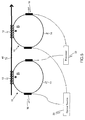
- FIG. 6 is a schematic view of a reactive compensation system incorporating an embodiment of a current system in accordance with an embodiment of the present invention.
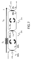
- FIG. 7 is a schematic view of a double ring system in accordance with one example of the present invention.
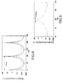
- FIG. 8 is a graph illustrating expected spectral responses of the double ring system for the example of FIG. 7.
- FIG. 9 is an enlarged view of a section of interest in the graph of FIG. 8.
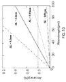
- FIG. 10 is a graph illustrating expected accuracy vs. wavelength resolution and differential length for the example of FIG. 7.
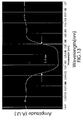
- FIG. 11 is a graph illustrating experimental results of wavelength shift vs. phase shift for the example of FIG. 7.
- FIG. 12 is a graph illustrating experimental results of current vs. amplitude for the example of FIG. 7.
- FIG. 13 is a graph illustrating experimental results of a spectrum including a demonstrated channel for the example of FIG. 7.
- As used herein, "adapted to", "configured" and the like refer to devices in a system to allow the elements of the system to cooperate to provide a described effect; these terms also refer to operation capabilities of electrical or optical elements such as analog or digital computers or application specific devices (such as an application specific integrated circuit (ASIC)), amplifiers or the like that are programmed to provide an output in response to given input signals, and to mechanical devices for optically or electrically coupling components together.
- As used herein, the term "current" can refer to either alternating current (AC) or direct current (DC).
- The drawings and illustrations herein are for the purpose of describing an embodiment or aspect of the invention and are not intended to limit the invention.
- Embodiments of the present invention relate to magneto optical sensors for estimating a parameter selected from the group consisting of a current, a magnetic field, or combinations thereof. In one embodiment of the present invention, as shown in FIG. 1, a resonant frequency tunable magneto-
optical loop resonator 10, is configured to receive an originating optical signal and to counter propagate the signal through the resonator. The loop resonator comprises a magneto-optical sensing element 12 coupled to awaveguide 14 to form a resonator structure. The waveguide may comprise either a guided waveguide or a free-space beam.Light splitter 16, which may comprises a beam splitter, fiber, or waveguide directional coupler, for example, separates the incoming light into the two counter-propagating arms of the loop resonator. Theloop resonator 10 is further configured to send a recombined signal or modulated signal out of the loop resonator into a transmitted port (shown as optical fiber 24) and reflected port (shown as optical fiber 22). - Faraday rotation is the rotation of polarization of light by a magneto-optic material due to the presence of a magnetic field parallel to the direction of propagation of light. Faraday effect induced non-reciprocal phase shift or non-reciprocal refractive index shift is a change in the velocity of propagation in the presence of a magnetic field parallel to the direction of propagation of light. This change reverses sign if either the field or the propagation direction is reversed. The non-reciprocal phase shift is proportional to the Faraday rotation or the Verdet constant of the material.
- The current I in a conductor is proportional to the line integral of the magnetic flux density B enclosed by a closed loop s, and is given by

- If a magneto-optical sensing element is placed in the magnetic field of a current carrying conductor, a light propagating through a magneto-optical sensing element in a direction parallel to the magnetic field intensity H, experiences a non reciprocal phase shift due to Faraday effect. The non-reciprocal phase shift ΔΦ is given by

- The phase shift reverses sign if either the field or the propagation direction is reversed. Therefore the phase shift change between counter two propagating light waves is given by

- If the magneto-optical sensing element is a coiled optical fiber element with N turns, then the phase shift is given by

- The resonant frequency f of a loop resonator is a function of the refractive index n of the resonator material and the length L1 of the loop resonator. The free spectral range (FSR), the frequency spacing between two adjacent modes of the resonator, is given by

- If a resonator loop with a magneto-optical sensing element with counter propagating light waves is placed in the magnetic field of a current carrying conductor, the resonance frequency of the loop resonator will be a sensitive function of the non-reciprocal phase changes experienced by the two counter-propagating light waves in the loop. The resonant frequency of the resonator (or wavelength) is obtained by the frequency filtered by the resonator and can give a precise estimation of the applied magnetic field. The non-reciprocal index change within the resonator results in a frequency shift Δf of the resonant frequency. A phase shift of 2π corresponds to a frequency shift equal to the FSR. Therefore, the non-reciprocal phase shift corresponding to a frequency shift Δf is given by

- The estimated current for a single loop resonator is therefore given by

- If a ring filter with a resonator length L2 is coupled to the loop resonator with the sensing element, the estimated current is then given by

- Obtaining the frequency of the resonator or the frequency filtered by the resonator can provide a precise estimation of the applied magnetic field. The current carried through the conductor can then be estimated. All other effects such as stress and temperature are reciprocal in regards to the counter-propagating light inside the loop, such that the relative phase noises cancel each when the two waves combine at the
light splitter 16. - In the embodiment shown in FIG. 1, a non-limiting example of the magneto-
optical sensing element 12 includes a coiled optical fiber element. The optical fiber coil may be looped around the current carrying conductor in several turns to sense the magnetic field. In one embodiment of the sensing element, the sensing element comprises an erbium or ytterbium doped multiple-turn coiled optical fiber element. For example, the number of turns in a multiple-turn coiled optical fiber element coil is about 200. - Non-limiting examples of
optical waveguides 14 include optical fibers, waveguide structures including glass, polymer waveguide structures, semiconductor material waveguide structures or period of free-space connection structures. Loop resonators with optical waveguides of different geometries, different mode structures and varying refractive index distribution are within the scope of this invention - An
optical source 20 is configured for sending an originating optical signal that is coupled into at least one magneto-optical loop resonator 10 through anoptical fiber 22. A non-limiting example of anoptical source 20 includes a broadband source. A broadband source is defined as a source or collection of sources capable of emitting light over a range of wavelengths. The broadband source may comprise a single wavelength tunable laser or a multi-wavelength broadband laser, for example. At least onelight splitter 16 is used to couple the originating signal into the loop resonator and the modulated signal out of the loop resonator. - A
processor 30 is configured for receiving the modulated signal from the magneto-optical loop resonator 10 through anoptical fiber 24. Typically, the processor also functions as a wavelength demultiplexer to resolve the resonance responses from each sensor. The processor may include one or more wavelength de-multiplexing elements, optical spectral meters, wavelength meters, photodetectors, differential amplifiers, and analog to digital converters. The wavelength demultiplexing element may comprise an array waveguide grating, a transmission or a deflection grating with a detection circuit tunable device such as a Fabry Perot interferometer, a ring resonator or a filter, for example. In a further embodiment of the present invention, theprocessor 40 and theoptical source 30 are integrated into a single unit to form anoptical interrogator module 50. In still further an embodiment of the present invention, part of the originating signal is sent to the processor as a reference signal to help extract a substantially accurate parameter value. - In another embodiment of the present invention as shown in FIG 2, the magneto-
optical loop resonator 10 is coupled to at least onering filter 18. This enables the adjustment of a wide range of parameters such as Free Spectral Ranges (FSR), Full Width Half Maximum (FWHM) and filter finesse. Furthermore, the ring filter can be used as a reference for temperature compensation of the loop resonator. Non-limiting examples of a ring filter include a loop resonator and a ring resonator. By choosing a desired coupling ratio, the frequency characteristics of the loop resonator―ring filter combination can be configured. - In a non-limiting example, a magneto-optical loop resonator with a 200-turn optical fiber sensing element is coupled to a resonator filter, wherein the difference in resonator lengths ΔL is in the range of about 0.01 mm to about 0.1mm. A lower ΔL value results in higher frequency resolution and higher accuracy in the estimated current. Such a system would typically exhibit a sub-nanometer resolution and could, for example, estimate a 3000 ampere current flowing through a conductor with an accuracy of 1% or better.
- In a further embodiment of the present invention as shown in FIG 3, the magneto-
optical sensing head 12 is a magneto-optical crystal 12 with a desirable Verdet constant. Non-limiting examples of magneto-optical crystals include terbium gallium garnet (TGG), terbium doped borosillicate glass, rare earth ion, erbium doped glass, ytterbium doped glass or LiNbO3. - The above described embodiments were primarily described in terms of a single magneto-optical loop resonator sensor, an optical source, and a processor, for purposes of example, however, each system may include one or more of such elements and "a" as used herein is intended to mean "at least one." When a plurality of loop resonators are used, the output signal from one loop resonator may be coupled into the input of a second loop resonator. In one example, a system in accordance with an embodiment of the present invention has at least two of the magneto optical loop resonators having different resonant frequencies. In a second example, the system has at least two resonators with the same resonant frequency.
- One embodiment of the present invention where a plurality of magneto-optical loop resonators is used is a distributed current estimation system as shown in FIG 4. The sensors are used in a distributed architecture with magneto
optical loop resonators 10 with different resonant frequencies being located in multiple locations to sense current flowing throughdifferent conductors 40. An originating signal from abroadband source 20 is coupled into the input of afirst loop resonator 10. The modulated signal from the final resonator is input into the processor. The sensors can be cascaded and can be remotely distinguished by their different resonant frequency. - In one embodiment of the present invention, the distributed current estimation system is embodied in a power substation. In a power grid, power distribution to multiple transmission lines typically occurs in a power substation. Desirably, a power station includes a distributed current estimation system to monitor current flow in multiple transmission lines.
- In another embodiment of the present invention, the distributed current estimation system is embodied in a power monitoring system in a transportation system. In a non-limiting example, a transportation system, wherein electrical power generation and distribution occurs within the transportation system, includes a power monitoring system comprising a distributed current estimation system for sensing current .
- An embodiment of the present invention where a plurality of magneto-optical loop resonators are used, is a differential current estimation system as shown in Fig. 5. It is desirable to have a system to estimate the difference between current flowing at two points along the same conductor. Such measurements may be used for differential fault current relaying in electric power systems.
- Difference in current can also provide information about the condition of the insulation surrounding the conductor. For example, small leakage currents to ground, through defective insulation at one point along a conductor, will typically lead to unequal currents being estimated at two points on either side of the defective insulation.
- The system is capable of obtaining the differential signal between current flowing at two points along the same conductor. At least two magneto-optical
loop resonator sensors 10 are placed in the field of a current carryingconductor 40 at different points along the same conductor. The optical signal from anoptical source 20 is coupled into each loop resonator and the modulated optical signal from each loop resonator is detected and processed by aprocessor 30 to extract the difference current between two points in a conductor. - In another embodiment of the present system is a ground fault detection system. In one example, a ground fault detection system comprises two or more magneto-optical sensors configured to measure current in two or more conductors or power lines to measure unbalanced load in the conductors or power lines. Such a ground fault detection system can be implemented in a three-phase AC system with a balanced load, to detect any imbalance in the system and is within the scope of this invention.
- In an illustrated embodiment in accordance with the present invention as shown in FIG 6 is a reactive compensation system for power transmission and distribution (T&D) networks. In reactive compensation systems for power T&D networks several magneto-
optical loop resonators 10 with magneto-optic sensing elements 12 completely isolated from ground potential are mounted at several points on conductors in atransmission network 60. Each loop resonator may further be coupled to at least onering filter 18. Theoptical interrogator module 50 interrogates the sensors by sending an originating broadband signal along at least oneoptical fiber 22. Eachloop resonator sensor 10 is configured to respond in different wavelength regions. The loop resonator sensor responds to changes in current causing the filtered frequency to change. Theoptical interrogator module 50, from at least oneoptical fiber 24, receives the resulting modulated optical signal. The optical signal originating from different magneto-optical sensors is demultiplexed by demultiplexers, and converted to electric signals by photodetectors housed in theoptical interrogator module 50. The signal is further processed and the information on current flow at various points on the network is passed on to a controller to enable dynamic control of the power flow in the system. - In an aspect of the present invention, a method for estimating a parameter selected from the group consisting of a current, a magnetic field, or combinations thereof, comprises the steps of providing at least one frequency tunable magneto-optical loop resonator with a sensing element, positioning the sensing element in a magnetic field to be sensed, coupling an originating signal from a source into the at least one loop resonator; propagating the originating signal along two counter propagating directions through two arms of the loop resonator and detecting a modulated signal from the at least one resonator. The method further includes providing a processor for determining the value of the parameter. The method further includes configuring the processor for difference current estimation.
- In a further aspect of this invention a method for estimating a parameter selected from the group consisting of a current, a magnetic field, or combinations thereof includes configuring multiple resonators with different resonant frequencies and positioning them in the magnetic field of different conductors to form a distributed network, sending an originating signal through the multiple loop resonators, configuring the processor for demultiplexing the received modulated signal and estimating the parameter.
- In an embodiment, which may be an alternative or used in combination with the frequency-multiplexing embodiment, a time division-multiplexing scheme is used. In this embodiment, modulated signals from the magneto-optical sensors are resolved by observing the signals at different times. In such an embodiment the magneto-optical sensors are connected at different fiber lengths to the source and or the processor, the time of arrival of modulated signals will be different for each sensor.
- A non-limiting example is illustrated in FIG. 7. Two
resonators coupler 116. Aninput coupler 216 inresonator 210 is 50:50 and anoutput coupler 316 inresonator 310 is 98:2. The coupling ratios in the couplers are chosen to optimize the spectral responses per as shown in FIGs. 8 and 9 (graphs illustrating an expected spectral response of the double ring system for the example of FIG. 7) with the solid line representing the system at room temperature and the dashed line representing the system at a temperature of about 200 degrees Celsius above room temperature. The temperature induced wavelength shift is estimated to be less than about 1 GHz (0.008nm) over a 200 degree Celsius span. Based on a dual ring model with 200 turns and maximum current I=3000A, the accuracy of the current measurement can be estimated versus differential length ΔL=L1-L2 and wavelength resolution of the interrogation system as shown in FIG. 10. High accuracy of 0.3% can be achieved, for example, using ΔL=0.1mm and wavelength resolution of 40 pm. - A system in accordance with one embodiment of the present invention was used to measure a current flowing though a conductor sourced from an Agilent DC power source with variable current output. The current output by the source was variable from 0 Amperes to 700 Amperes. A magneto-optical loop resonator with a sensing element comprising a 120-turn optical fiber coil wrapped around the conductor was used to sense the current flowing through the conductor. A laser diode lasing in the region of about 1545 nm was used as an optical source, and the output used to interrogate the loop resonator. An interrogation system comprising a sweep meter was used to estimate the current. A sweep meter, for example from Precision Photonics, is typically used for sweeping the laser diode output wavelength. A wavelength monitor was used to monitor the wavelength. The resonance frequency of the loop resonator exhibited a wavelength shift of about 1.3 nm (1546 nm to 1547.3 nm) for a non-reciprocal phase shift of about .16 π. As the current was varied from about 0 to about 600 amperes, a wavelength shift of about 0.4 nm was observed as shown in FIG. 11. The wavelength shifts were converted to corresponding amplitude shifts using a wavelength filter around the center wavelength, and the current estimated by measuring the amplitudes is shown in FIG. 12. The response is linear within the current measurement range. The potential for multiplexing more wavelength length channels, in the above example, is high due to the over-all available spectrum of 50 nm (from 1520 nanometer to 1570 nanometer), and the demonstrated channel occupying a width of 1.4 nm, as shown in FIG. 13.
- The previously described embodiments of the present invention have many advantages, including eliminating polarization components, which consist of one third of the measurement setup being used in the polarimetric current sensors, hence increasing robustness against the environmental noises such as fiber bending and material stress. Sensing in the optical wavelength (frequency) domain allows linear, scalable and precision estimation for a high dynamic range without suffering saturation effects. The system for estimating current of the present invention desirably has a linear response over a large dynamic range.
Claims (9)
- A system for estimating a parameter selected from the group consisting of a current, a magnetic field, or combinations thereof, the system comprising resonant frequency tunable magneto-optical loop resonator (10), wherein the loop resonator comprises a magneto-optical sensing element (12) coupled to an optical waveguide (14); wherein the loop resonator is configured for receiving an originating optical signal, propagating the originating optical signal in two counter directions, and providing a modulated signal indicative of the parameter.
- The system of claim 1, wherein the sensing element (12) comprises an optical fiber coil comprising at least one looped element.
- The system of claim 1, wherein the sensing element comprises a magneto-optic crystal.
- The system of claim 1, further comprising a ring resonator filter (18), wherein the loop resonator is coupled to the ring resonator filter.
- A system for estimating a parameter selected from the group consisting of a current, a magnetic field, a change in current, a change in magnetic field, or combinations thereof, the system comprising a plurality of resonant frequency tunable magneto-optical loop resonators (10), wherein each loop resonator comprises a magneto-optical sensing element (12) coupled to an optical waveguide (14), wherein the loop resonators are each configured for receiving an originating optical signal, propagating the originating optical signal in two counter directions, and providing a respective modulated signal indicative of the parameter.
- The system of claim 5, wherein at least two of the loop resonators have different resonant frequencies.
- The system of claim 5, wherein at least two of the loop resonators have the same resonant frequency.
- The system of claim 5, wherein the output from at least one of the loop resonators is coupled into at least one other of the loop resonators.
- A distributed current estimation system comprising:a plurality of resonant frequency tunable magneto-optical loop resonators (10) with different resonant frequencies, wherein each loop resonator comprises a magneto-optical sensing element coupled to a waveguide;wherein each sensing element (12) is configured to estimate current flowing in a different conductor;
wherein the loop resonators are configured for receiving an originating optical signal originating from a broadband source (20), propagating the originating optical signal in counter directions, and providing a modulated signal indicative of the estimated currents to a processor (30).
Applications Claiming Priority (1)
| Application Number | Priority Date | Filing Date | Title |
|---|---|---|---|
| US11/010,530 US7277179B2 (en) | 2004-12-13 | 2004-12-13 | Magneto-optical sensors |
Publications (1)
| Publication Number | Publication Date |
|---|---|
| EP1669770A1 true EP1669770A1 (en) | 2006-06-14 |
Family
ID=35892369
Family Applications (1)
| Application Number | Title | Priority Date | Filing Date |
|---|---|---|---|
| EP05257283A Ceased EP1669770A1 (en) | 2004-12-13 | 2005-11-28 | Magneto-optical sensors |
Country Status (4)
| Country | Link |
|---|---|
| US (1) | US7277179B2 (en) |
| EP (1) | EP1669770A1 (en) |
| JP (1) | JP4993252B2 (en) |
| CN (1) | CN1808167B (en) |
Families Citing this family (23)
| Publication number | Priority date | Publication date | Assignee | Title |
|---|---|---|---|---|
| US7277179B2 (en) * | 2004-12-13 | 2007-10-02 | General Electric Company | Magneto-optical sensors |
| US10016148B2 (en) * | 2006-09-27 | 2018-07-10 | General Electric Company | Method and apparatus for correction of multiple EM sensor positions |
| US7460741B2 (en) * | 2006-12-29 | 2008-12-02 | Honeywell International Inc. | Fiber optic current sensor and method for sensing current using the same |
| US20080183064A1 (en) * | 2007-01-30 | 2008-07-31 | General Electric Company | Multi-sensor distortion detection method and system |
| CN100462756C (en) * | 2007-05-31 | 2009-02-18 | 浙江大学 | Nonreciprocal devices based on magneto-optic resonators |
| US20100309473A1 (en) * | 2007-12-21 | 2010-12-09 | Honeywell International Inc. | Fiber optic current sensor and method for sensing current using the same |
| US8068232B2 (en) * | 2008-04-01 | 2011-11-29 | The Board Of Trustees Of The Leland Stanford Junior University | Unidirectional crow gyroscope |
| US8718421B2 (en) * | 2008-09-05 | 2014-05-06 | Morton Photonics | Super-ring resonator based devices |
| JP5447002B2 (en) * | 2009-03-19 | 2014-03-19 | セイコーエプソン株式会社 | Magnetic field measuring device |
| US9019482B2 (en) | 2009-06-05 | 2015-04-28 | The Board Of Trustees Of The Leland Stanford Junior University | Optical device with fiber Bragg grating and narrowband optical source |
| US9025157B2 (en) | 2010-09-08 | 2015-05-05 | The Board Of Trustees Of The Leland Stanford Junior University | System and method for measuring perturbations using a slow-light fiber Bragg grating sensor |
| US8797540B2 (en) | 2010-09-08 | 2014-08-05 | The Board Of Trustees Of The Leland Stanford Junior University | Slow-light fiber Bragg grating sensor |
| CN102141691A (en) * | 2011-04-25 | 2011-08-03 | 东北大学 | Magnetic control tunable optical fiber comb filter |
| CN104377712A (en) * | 2014-11-28 | 2015-02-25 | 中电博瑞技术(北京)有限公司 | STATCOM (static VAR compensator) |
| EP3264110B1 (en) * | 2015-02-24 | 2022-05-18 | Hitachi, Ltd. | Optical fiber sensor and measurement device using same |
| EP3104183A1 (en) * | 2015-06-10 | 2016-12-14 | Lumiker Aplicaciones Tecnologicas S.L. | Current measuring equipment based on optical fiber for measuring the current circulating through a conductor and the associated method |
| US11408854B2 (en) | 2017-08-25 | 2022-08-09 | Case Western Reserve University | Magneto-optical detection and discernment of biofluid crystals |
| CN108957152B (en) * | 2018-07-02 | 2021-06-18 | 昆明理工大学 | An integrated optical waveguide field sensor system based on wavelength demodulation and its measurement method |
| JP7194327B2 (en) | 2018-07-03 | 2022-12-22 | スミダコーポレーション株式会社 | Magnetic field measuring device and magnetic field measuring method |
| CN108680780A (en) * | 2018-07-06 | 2018-10-19 | 南京溯极源电子科技有限公司 | A kind of leakage current measurement device and method |
| MY203105A (en) * | 2019-08-22 | 2024-06-09 | Petroliam Nasional Berhad Petronas | Magnetic field measurement cable and distributed-type well inside magnetic field measurement system |
| CN112578173B (en) * | 2019-09-27 | 2024-07-09 | 上海康阔光智能技术有限公司 | Optical lightning current measuring system and measuring method |
| CN115932364B (en) * | 2022-12-30 | 2026-03-03 | 湖北工业大学 | Dual-ring electromagnetic magneto-optical hybrid current transformer |
Citations (5)
| Publication number | Priority date | Publication date | Assignee | Title |
|---|---|---|---|---|
| US5564832A (en) | 1993-01-29 | 1996-10-15 | United Technologies Corporation | Birefringent active fiber laser sensor |
| JP2001028272A (en) | 1999-07-15 | 2001-01-30 | Mitsubishi Chemicals Corp | Electrolyte for lithium secondary battery and lithium secondary battery using the same |
| JP2001281272A (en) * | 2000-03-31 | 2001-10-10 | Toshiba Corp | Current / magnetic field measuring device |
| EP1195582A1 (en) | 2000-10-09 | 2002-04-10 | Eidgenössische Technische Hochschule Zürich | Fiber optic sensor with an optical resonator |
| JP2004301769A (en) | 2003-03-31 | 2004-10-28 | Toshiba Corp | Photocurrent measuring instrument and current differential protection system using the same |
Family Cites Families (14)
| Publication number | Priority date | Publication date | Assignee | Title |
|---|---|---|---|---|
| US4375680A (en) * | 1981-01-16 | 1983-03-01 | Mcdonnell Douglas Corporation | Optical acoustic sensor |
| EP0089275B1 (en) * | 1982-03-12 | 1986-05-28 | Thomson-Csf | Interferometric glass fibre current measuring device |
| US5108183A (en) * | 1989-08-31 | 1992-04-28 | The Board Of Trustees Of The Leland Stanford Junior University | Interferometer utilizing superfluorescent optical source |
| GB9213736D0 (en) | 1992-06-29 | 1992-08-12 | Univ Kent Kanterbury | Optical current sensor |
| JPH07191060A (en) * | 1993-12-27 | 1995-07-28 | Toshiba Corp | Photocurrent sensor |
| US5587791A (en) | 1994-09-27 | 1996-12-24 | Citeq | Optical interferometric current sensor and method using a single mode birefringent waveguide and a pseudo-depolarizer for measuring electrical current |
| US5644397A (en) * | 1994-10-07 | 1997-07-01 | The Texas A&M University System | Fiber optic interferometric circuit and magnetic field sensor |
| US6188811B1 (en) * | 1998-10-31 | 2001-02-13 | The Texas A&M Universtiy System | Fiber optic current sensor |
| US6301400B1 (en) * | 1998-11-12 | 2001-10-09 | Nxtphase Technologies Srl | Fiber optic current sensor having rotation immunity |
| US6434285B1 (en) * | 1998-12-31 | 2002-08-13 | Nxtphase Technologies Srl | Fiber optic difference current sensor |
| US6370289B1 (en) * | 2000-01-12 | 2002-04-09 | Kvh Industries, Inc. | Apparatus and method for electronic RIN reduction in fiber-optic sensors |
| US6670799B1 (en) * | 2000-05-03 | 2003-12-30 | Nxt Phase Corporation | Optical current measuring for high voltage systems |
| US6946827B2 (en) | 2001-11-13 | 2005-09-20 | Nxtphase T & D Corporation | Optical electric field or voltage sensing system |
| US7277179B2 (en) * | 2004-12-13 | 2007-10-02 | General Electric Company | Magneto-optical sensors |
-
2004
- 2004-12-13 US US11/010,530 patent/US7277179B2/en not_active Expired - Fee Related
-
2005
- 2005-11-28 EP EP05257283A patent/EP1669770A1/en not_active Ceased
- 2005-12-01 JP JP2005347491A patent/JP4993252B2/en not_active Expired - Fee Related
- 2005-12-13 CN CN2005101191793A patent/CN1808167B/en not_active Expired - Fee Related
Patent Citations (5)
| Publication number | Priority date | Publication date | Assignee | Title |
|---|---|---|---|---|
| US5564832A (en) | 1993-01-29 | 1996-10-15 | United Technologies Corporation | Birefringent active fiber laser sensor |
| JP2001028272A (en) | 1999-07-15 | 2001-01-30 | Mitsubishi Chemicals Corp | Electrolyte for lithium secondary battery and lithium secondary battery using the same |
| JP2001281272A (en) * | 2000-03-31 | 2001-10-10 | Toshiba Corp | Current / magnetic field measuring device |
| EP1195582A1 (en) | 2000-10-09 | 2002-04-10 | Eidgenössische Technische Hochschule Zürich | Fiber optic sensor with an optical resonator |
| JP2004301769A (en) | 2003-03-31 | 2004-10-28 | Toshiba Corp | Photocurrent measuring instrument and current differential protection system using the same |
Non-Patent Citations (3)
| Title |
|---|
| DONATI S ET AL: "MAGNETO-OPTICAL FIBRE SENSORS FOR ELECTRICAL INDUSTRY: ANALYSIS OF PERFORMANCES", IEE PROCEEDINGS J. OPTOELECTRONICS, INSTITUTION OF ELECTRICAL ENGINEERS. STEVENAGE, GB, vol. 135, no. 5, PART J, 1 October 1988 (1988-10-01), pages 372 - 382, XP000027004, ISSN: 0267-3932 * |
| PATENT ABSTRACTS OF JAPAN vol. 2002, no. 02 2 April 2002 (2002-04-02) * |
| PATENT ABSTRACTS OF JAPAN vol. 2003, no. 12 5 December 2003 (2003-12-05) * |
Also Published As
| Publication number | Publication date |
|---|---|
| CN1808167A (en) | 2006-07-26 |
| JP2006170983A (en) | 2006-06-29 |
| US20060126990A1 (en) | 2006-06-15 |
| JP4993252B2 (en) | 2012-08-08 |
| US7277179B2 (en) | 2007-10-02 |
| CN1808167B (en) | 2010-09-08 |
Similar Documents
| Publication | Publication Date | Title |
|---|---|---|
| US7277179B2 (en) | Magneto-optical sensors | |
| US5963034A (en) | Electro-optic electromagnetic field sensor system with optical bias adjustment | |
| KR100488221B1 (en) | Fiber Bragg grating sensor system | |
| US4370612A (en) | Interferometric optical fiber electric current measuring device | |
| EP3066423B1 (en) | Single-end brillouin optical distributed sensing device and method | |
| WO1998008105A1 (en) | Fiber optics apparatus and method for accurate current sensing | |
| EP2274569B1 (en) | High voltage measurement device using poled fibers | |
| EP1302774B1 (en) | Sagnac interferometer current sensor | |
| US6434285B1 (en) | Fiber optic difference current sensor | |
| EP4103913B1 (en) | High sampling rate optical fiber sensor | |
| Chu et al. | Optical voltage sensors based on integrated optical polarization-rotated reflection interferometry | |
| Abad et al. | Interrogation of wavelength multiplexed fiber Bragg gratings using spectral filtering and amplitude-to-phase optical conversion | |
| WO1992015895A1 (en) | Apparatus and methods for measuring magnetic fields and electric currents | |
| Bohnert et al. | Coherence-tuned interrogation of a remote elliptical-core, dual-mode fiber strain sensor | |
| US7394982B2 (en) | Current sensing system | |
| Zhao et al. | Fiber Bragg grating sensor interrogation using chirped fiber grating-based Sagnac loop | |
| US6211982B1 (en) | Remote sensor with waveguide optics telemetry | |
| Nascimento et al. | Intensity-modulated optical fiber sensor for AC magnetic field detection | |
| Heredero et al. | Micromachined low-finesse Fabry-Perot interferometer for the measurement of DC and AC electrical currents | |
| US20250044326A1 (en) | Optically isolated lightwave current sensor | |
| EP3602092B1 (en) | A voltage measuring system with an optical fibre cable | |
| EP2570799A1 (en) | Optical sensor arrangement and method for measuring an observable | |
| Swart et al. | Differentiating fiber optic reflective ring interferometer for alternating current measurements | |
| KR100307639B1 (en) | Current / temperature measurement optical sensor using multi-wavelength light source and its method | |
| KR100335244B1 (en) | An apparatus and a method for the measurement of phase fluctuation of optical fiber |
Legal Events
| Date | Code | Title | Description |
|---|---|---|---|
| PUAI | Public reference made under article 153(3) epc to a published international application that has entered the european phase |
Free format text: ORIGINAL CODE: 0009012 |
|
| AK | Designated contracting states |
Kind code of ref document: A1 Designated state(s): AT BE BG CH CY CZ DE DK EE ES FI FR GB GR HU IE IS IT LI LT LU LV MC NL PL PT RO SE SI SK TR |
|
| AX | Request for extension of the european patent |
Extension state: AL BA HR MK YU |
|
| 17P | Request for examination filed |
Effective date: 20061214 |
|
| 17Q | First examination report despatched |
Effective date: 20070112 |
|
| AKX | Designation fees paid |
Designated state(s): DE FR GB |
|
| APBK | Appeal reference recorded |
Free format text: ORIGINAL CODE: EPIDOSNREFNE |
|
| APBN | Date of receipt of notice of appeal recorded |
Free format text: ORIGINAL CODE: EPIDOSNNOA2E |
|
| APBR | Date of receipt of statement of grounds of appeal recorded |
Free format text: ORIGINAL CODE: EPIDOSNNOA3E |
|
| APAF | Appeal reference modified |
Free format text: ORIGINAL CODE: EPIDOSCREFNE |
|
| APBT | Appeal procedure closed |
Free format text: ORIGINAL CODE: EPIDOSNNOA9E |
|
| STAA | Information on the status of an ep patent application or granted ep patent |
Free format text: STATUS: THE APPLICATION HAS BEEN REFUSED |
|
| 18R | Application refused |
Effective date: 20140925 |