EP1669716A1 - Steering angle estimating device for vehicle - Google Patents
Steering angle estimating device for vehicle Download PDFInfo
- Publication number
- EP1669716A1 EP1669716A1 EP04773330A EP04773330A EP1669716A1 EP 1669716 A1 EP1669716 A1 EP 1669716A1 EP 04773330 A EP04773330 A EP 04773330A EP 04773330 A EP04773330 A EP 04773330A EP 1669716 A1 EP1669716 A1 EP 1669716A1
- Authority
- EP
- European Patent Office
- Prior art keywords
- wheels
- wheel
- steering angle
- vehicle
- estimating apparatus
- Prior art date
- Legal status (The legal status is an assumption and is not a legal conclusion. Google has not performed a legal analysis and makes no representation as to the accuracy of the status listed.)
- Withdrawn
Links
Images

Classifications
-
- B—PERFORMING OPERATIONS; TRANSPORTING
- B62—LAND VEHICLES FOR TRAVELLING OTHERWISE THAN ON RAILS
- B62D—MOTOR VEHICLES; TRAILERS
- B62D15/00—Steering not otherwise provided for
- B62D15/02—Steering position indicators ; Steering position determination; Steering aids
-
- B—PERFORMING OPERATIONS; TRANSPORTING
- B62—LAND VEHICLES FOR TRAVELLING OTHERWISE THAN ON RAILS
- B62D—MOTOR VEHICLES; TRAILERS
- B62D15/00—Steering not otherwise provided for
- B62D15/02—Steering position indicators ; Steering position determination; Steering aids
- B62D15/021—Determination of steering angle
- B62D15/024—Other means for determination of steering angle without directly measuring it, e.g. deriving from wheel speeds on different sides of the car
-
- B—PERFORMING OPERATIONS; TRANSPORTING
- B62—LAND VEHICLES FOR TRAVELLING OTHERWISE THAN ON RAILS
- B62D—MOTOR VEHICLES; TRAILERS
- B62D15/00—Steering not otherwise provided for
Definitions
- the present invention relates to a steering angle estimating apparatus for vehicle that estimates a steering angle of a vehicle using a steering wheel rotational velocity of the vehicle, and an electric power steering apparatus containing the estimating apparatus.
- a conventional steering angle estimating apparatus for vehicle is disclosed in, for example, Japanese Patent No. 2614348 B2 (document 1).
- the estimating apparatus has a steering angle detecting sensor that detects a steering angle of a steering wheel, a left wheel velocity sensor that detects a velocity of the left wheels, a right wheel velocity sensor that detects a velocity of the right wheels, an estimated steering angle calculating means that calculates an estimated steering angle based on the velocity of the left wheels obtained by the left wheel velocity sensor and the velocity of the right wheels obtained by the right wheel velocity sensor, and a neutral position calculating means that calculates a neutral position of the steering angle of the steering wheel after a phase difference between a signal from the steering angle detecting sensor and the estimated steering angle obtained by the estimated steering angle calculating mean is taken into consideration.
- Japanese Patent Application Laid-Open No. 2003-14450 A discloses a steering angle estimating apparatus for vehicle, which estimates a steering angle of a vehicle using a pair of rotating sensors which detect rotating states of the right and left wheels, having: a velocity detecting means that detects rotational velocities of the right and left wheels based on outputs from the paired rotating sensors; a velocity ratio calculating means that calculates a rotational velocity ratio of the rotational velocity of the left wheels to the rotational velocity of the right wheels detected by the velocity detecting means; a steering angle calculating means that calculates the steering angle of the vehicle based on the rotational velocity ratio calculated by the velocity ratio calculating means.
- the estimating apparatus in the document 2 determines a steady state by comparing a rotational velocity ratio of two front wheels with a rotational velocity ratio of two rear wheels, a difference in turning radius between the front wheels and the rear wheels is not accurately reflected, and thus the above steady determination accuracy is not occasionally exact according to the steering angle. When only one wheel slips, the steering angle cannot be estimated.
- the present invention is devised in view of the above problems, and it is an object of the present invention to provide a steering angle estimating apparatus for vehicle that can accurately determine the steady state at all steering angles, and can estimate the steering angle as much as possible even in the case of a non-steady state such that one wheel slips. Its another object is to provide an electric power steering apparatus which contains the steering angle estimating apparatus for vehicle which can accurately determine the steady state at all the steering angles and can estimate the steering angle as much as possible even in a case where the steady state is not obtained.
- the present invention relates to a steering angle estimating apparatus for vehicle that has wheel rotational velocity sensors for four wheels, respectively, and estimates a steering angle of a vehicle based on wheel rotational velocities from the wheel rotational velocity sensors, and the object of the present invention is achieved by comparing relationships in the wheel rotational velocities between two combinations of front and rear wheels on right and left sides and detecting that slip of the four wheels is detected.
- the object of the present invention is achieved more effectively by that when the two combinations of the front and rear wheels on the right and left sides match with each other, even if one of the four wheels slips, this wheel is specified and the correct steering angle can be estimated.
- turning radiuses of four wheels fl, fr, rl and rr are respectively designated by Rfl, Rfr, Rrl and Rrr
- steering angles of the front wheels fl and fr are respectively designated by ⁇ 1 and ⁇ r
- an axle distance of a vehicle is designated by L
- a vehicle width is designated by E.
- a turning radius of the center of the front wheel axle is designated by Rf
- a turning radius of the center of the rear wheel axle is designated by Rr.
- the relationships among the steering angle ⁇ of the center of the front wheel axle, the steering angle ⁇ 1 of the left front wheel and the steering angle ⁇ r of the right front wheel is determined by a vehicle type. If they establish the following mathematical formulas 5 and 6, the mathematical formulas 1 to 4 hold by the common steering angle ⁇ , axle distance L of the vehicle and vehicle width E. As shown in FIG. 2, k1 designates a ratio of the steering angle to a steering angle of an inner ring, and k2 designates a ratio of the steering angle to a steering angle of an outer ring.
- the wheel velocities ⁇ fl , ⁇ fr , ⁇ rl and ⁇ rr establish all the mathematical formulas 1 to 4, but when a wheel slips, a mathematical formula which does not establish these mathematical formulas holds. Since this mathematical formula contains a wheel which slips, all the mathematical formulas 1 to 4 are checked so that the slipped wheel can be specified (excluding the case where two or more wheels slip). For example, in the case where the relationship between the rear wheels and the right front wheel is appropriate, as shown in FIG. 3, a determination can be made that only the left front wheel slips. Since one wheel starts to slip in most cases, the present invention is a method which is sufficient for specifying the wheel which slips first.
- FIGs . 4 and 5 show flowcharts of the estimating calculation and the present invention is explained.
- a vehicle is constituted so that all the four wheels are equipped with a wheel rotational velocity sensor that detects a rotational velocity of a wheel.
- Step S2 After the vehicle repeats an operation for clearing all duration times (Step S2) for which a condition is satisfied until the vehicle is accelerated to a predetermined velocity v 0 (Step S1), when the wheels reach the predetermined velocity v 0 , the rotational velocities ⁇ fl , ⁇ fr , ⁇ rl and ⁇ rr of the wheels are read from the wheel rotational velocity sensors (Step S3).
- the rotational velocities ⁇ fl and ⁇ fr of the front wheels, and the rotational velocities ⁇ rl and ⁇ rr of the rear wheels are used so that the estimated steering angles ⁇ front and ⁇ rear are calculated according to the mathematical formulas 1 and 2 (Step S4).
- the steering angles of the inner and outer rings may be estimated not by a determination at the time of right-hand turn and left-hand turn and the multiplication of the coefficients (k1 and k2) but by a data table about the steering angles which is prepared. Further, a data table for obtaining cosine values of the inner and outer rings directly based on the steering angle ⁇ of the center of the front wheel axle may be utilized.
- are obtained, and a determination is made whether the absolute value
- Step S11 When the absolute value
- Is larger than the set value do the condition is regarded as being unsatisfied, so that the timer for d rr is cleared (Step S12) and the sequence goes to a next operation.
- the condition (the error is small) is regarded as being satisfied, so that a timer for d r1 is counted up (Step S14).
- is larger than the set value do, the condition is regarded as being unsatisfied so that the timer for d r1 is cleared (Step S15) and the sequence goes to a next operation.
- Step S20 a determination is made whether the absolute value
- is not more than the set value do, the condition (the error is small) is regarded as being satisfied, so that a timer for d fr is counted up (Step S21).
- is larger than the set value do, the condition is regarded as being unsatisfied, so that the timer for d fr is cleared (Step S22) and the sequence goes to a next operation.
- is not more than the set value do, the condition (the error is small) is regarded as being satisfied, the timer for d fl is counted up (Step S24).
- is larger than the set value d 0 , the condition is regarded as being unsatisfied, so that the timer for d f1 is cleared (Step S25) and the sequence goes to next duration time processes.
- a module of the flowchart in FIGs. 4 and 5 is repeated in constant cycle, and when the condition is continuously satisfied, the respective timers are kept to be counted up, but when the condition is not satisfied, the timers are cleared to 0 immediately.
- the estimated angle is determined as ⁇ rear and the operation is ended (Step S27).
- the duration time for d rr or the duration time for d r1 is shorter than the predetermined time t, a determination is made whether duration time for d fr or duration time for d f1 is not less than the predetermined time t (Step S28).
- Step S29 When the duration time for d fr or the duration time for d fl is not less than the predetermined time t, the estimated angle is determined as ⁇ front and the operation is ended (Step S29).
- the sequence returns to the step S1 so that the above operation is repeated.
- the rotational ratios of the front and rear wheels ⁇ rl / ⁇ fl and ⁇ rr/ ⁇ fr are calculated based on the rotational velocities ⁇ fl , ⁇ fr , ⁇ rl and ⁇ rr of the front and rear wheels on the right and left, so that the calculated rotational ratios are compared with cos ⁇ fl , cos ⁇ fr , cos ⁇ rl and cos ⁇ rr .
- the determination is made as to the right rear wheel, the left rear wheel, the right front wheel and the left front wheel in this order, but the order is arbitrary.
- the steering angle estimating apparatus for vehicle of the present invention the relational expression on which the ratio of the wheel turning radiuses in the steady state is accurately reflected is used, so that the steady state can be determined more definitely than conventional methods. Further, in the case where one wheel slips, the estimated steering angles of the four sets of the right and left front wheels, the right and left rear wheels, left front and rear wheels and the right front and rear wheels are compared, so that the wheel which slips can be specified, and the correct estimated steering angle can be selected from the other wheels.
- the steering angle estimating apparatus for vehicle of the present invention can accurately determine the steady states at all the steering angles, the estimating apparatus can be applied to vehicles such as automobiles optimally. Since this estimating apparatus can estimate the steering angle as much as possible even in the case of a non-steady state, this estimating apparatus is effective for vehicle apparatuses.
Landscapes
- Engineering & Computer Science (AREA)
- Chemical & Material Sciences (AREA)
- Combustion & Propulsion (AREA)
- Transportation (AREA)
- Mechanical Engineering (AREA)
- Steering Control In Accordance With Driving Conditions (AREA)
- Length Measuring Devices With Unspecified Measuring Means (AREA)
Abstract
The present invention provides a steering angle estimating apparatus for vehicle that can accurately determine a steady state at all the steering angles, and can estimate the steering angle as much as possible even in a non-steady state. In the steering angle estimating apparatus for vehicle that has wheel rotational velocity sensors for four wheels, respectively, and estimates the steering angle of the vehicle based on wheel rotational velocities from the wheel rotational velocity sensors, relationships in the wheel rotational velocities between respective combinations of two wheels of the front and rear wheels on right and left sides are compared so that slip of the four wheels is detected.
Description
- The present invention relates to a steering angle estimating apparatus for vehicle that estimates a steering angle of a vehicle using a steering wheel rotational velocity of the vehicle, and an electric power steering apparatus containing the estimating apparatus.
- A conventional steering angle estimating apparatus for vehicle is disclosed in, for example, Japanese Patent No. 2614348 B2 (document 1). The estimating apparatus has a steering angle detecting sensor that detects a steering angle of a steering wheel, a left wheel velocity sensor that detects a velocity of the left wheels, a right wheel velocity sensor that detects a velocity of the right wheels, an estimated steering angle calculating means that calculates an estimated steering angle based on the velocity of the left wheels obtained by the left wheel velocity sensor and the velocity of the right wheels obtained by the right wheel velocity sensor, and a neutral position calculating means that calculates a neutral position of the steering angle of the steering wheel after a phase difference between a signal from the steering angle detecting sensor and the estimated steering angle obtained by the estimated steering angle calculating mean is taken into consideration.
- Further, Japanese Patent Application Laid-Open No. 2003-14450 A (document 2) discloses a steering angle estimating apparatus for vehicle, which estimates a steering angle of a vehicle using a pair of rotating sensors which detect rotating states of the right and left wheels, having: a velocity detecting means that detects rotational velocities of the right and left wheels based on outputs from the paired rotating sensors; a velocity ratio calculating means that calculates a rotational velocity ratio of the rotational velocity of the left wheels to the rotational velocity of the right wheels detected by the velocity detecting means; a steering angle calculating means that calculates the steering angle of the vehicle based on the rotational velocity ratio calculated by the velocity ratio calculating means.
- In document 3 (Journal of the Institute of Electrical Engineers of Japan, vol. 120, No. 2 "New tire slipping detecting method which does not require vehicle velocity information in electronic vehicle", 2000), a motion equation of wheels and a motion equation of a vehicle body are obtained so that a slip ratio is estimated by using wheel velocities and a vehicle velocity as state variables.
- However, with the technique in the
document 1, only a neutral point of steering is estimated, and thus an estimation possible range is narrow. Since only a velocity of one set of the right wheel and left wheel is used for the estimation, accurate estimation cannot be made. - Since the estimating apparatus in the
document 2 determines a steady state by comparing a rotational velocity ratio of two front wheels with a rotational velocity ratio of two rear wheels, a difference in turning radius between the front wheels and the rear wheels is not accurately reflected, and thus the above steady determination accuracy is not occasionally exact according to the steering angle. When only one wheel slips, the steering angle cannot be estimated. - Further, in the technique in the document 3, a torque for driving the tires should be detected, and motor driving is necessary or a driving torque sensor is necessary.
- The present invention is devised in view of the above problems, and it is an object of the present invention to provide a steering angle estimating apparatus for vehicle that can accurately determine the steady state at all steering angles, and can estimate the steering angle as much as possible even in the case of a non-steady state such that one wheel slips. Its another object is to provide an electric power steering apparatus which contains the steering angle estimating apparatus for vehicle which can accurately determine the steady state at all the steering angles and can estimate the steering angle as much as possible even in a case where the steady state is not obtained.
- The present invention relates to a steering angle estimating apparatus for vehicle that has wheel rotational velocity sensors for four wheels, respectively, and estimates a steering angle of a vehicle based on wheel rotational velocities from the wheel rotational velocity sensors, and the object of the present invention is achieved by comparing relationships in the wheel rotational velocities between two combinations of front and rear wheels on right and left sides and detecting that slip of the four wheels is detected.
- Further, the object of the present invention is achieved more effectively by that when the two combinations of the front and rear wheels on the right and left sides match with each other, even if one of the four wheels slips, this wheel is specified and the correct steering angle can be estimated.
-
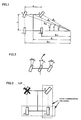
- FIG. 1 is a diagram explaining a principle of the present invention;
- FIG. 2 is a diagram explaining a steering angle;
- FIG. 3 is a diagram illustrating an example of slipping wheel;
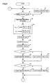
- FIG. 4 is a part of a flowchart illustrating an operation example of the present invention; and
- FIG. 5 is a part of a flowchart illustrating the operation example of the present invention.
- As shown in FIG. 1, in the present invention, turning radiuses of four wheels fl, fr, rl and rr are respectively designated by Rfl, Rfr, Rrl and Rrr, steering angles of the front wheels fl and fr are respectively designated by α1 and αr, an axle distance of a vehicle is designated by L, and a vehicle width is designated by E. A turning radius of the center of the front wheel axle is designated by Rf, and a turning radius of the center of the rear wheel axle is designated by Rr. When wheel velocities (wheel angular velocities) of the left front wheel wheels fl, the right front wheel fr, the left rear wheel rl and the right rear wheel rr are respectively designated by ωfl, ωfr, ωrl and ωrr, it is known that the steering angle α of the center of the vehicle body and the wheel velocities ωf1, ωfr, ωrl and ωrr establish the following relationships:


- According to any one of the
mathematical formulas 

- The relationships among the steering angle α of the center of the front wheel axle, the steering angle α1 of the left front wheel and the steering angle αr of the right front wheel is determined by a vehicle type. If they establish the following mathematical formulas 5 and 6, the
mathematical formulas 1 to 4 hold by the common steering angle α, axle distance L of the vehicle and vehicle width E. As shown in FIG. 2, k1 designates a ratio of the steering angle to a steering angle of an inner ring, and k2 designates a ratio of the steering angle to a steering angle of an outer ring.

- When the vehicle can be turned in a steady state, the wheel velocities ωfl, ωfr, ωrl and ωrr establish all the
mathematical formulas 1 to 4, but when a wheel slips, a mathematical formula which does not establish these mathematical formulas holds. Since this mathematical formula contains a wheel which slips, all themathematical formulas 1 to 4 are checked so that the slipped wheel can be specified (excluding the case where two or more wheels slip). For example, in the case where the relationship between the rear wheels and the right front wheel is appropriate, as shown in FIG. 3, a determination can be made that only the left front wheel slips. Since one wheel starts to slip in most cases, the present invention is a method which is sufficient for specifying the wheel which slips first. - FIGs . 4 and 5 show flowcharts of the estimating calculation and the present invention is explained. In the present invention, a vehicle is constituted so that all the four wheels are equipped with a wheel rotational velocity sensor that detects a rotational velocity of a wheel.
- After the vehicle repeats an operation for clearing all duration times (Step S2) for which a condition is satisfied until the vehicle is accelerated to a predetermined velocity v0 (Step S1), when the wheels reach the predetermined velocity v0, the rotational velocities ωfl, ωfr, ωrl and ωrr of the wheels are read from the wheel rotational velocity sensors (Step S3). The rotational velocities ωfl and ωfr of the front wheels, and the rotational velocities ωrl and ωrr of the rear wheels are used so that the estimated steering angles αfront and αrear are calculated according to the
mathematical formulas 1 and 2 (Step S4). - A determination is made whether the right wheels or the left wheels are inner rings or outer rings based on the estimated steering angles αfront and αrear, the ratio k1 of the preset steering angle to the steering angle of the inner rings is multiplied by the ratio k2 of the steering angle to the steering angle of the outer ring, and the steering angle α1 of the left wheels and the steering angle αr of the right angles are estimated so that their cosine values are calculated (Step S5, cosαfl and cosαfr from the front wheels, and cosαrl and cosαrr from the rear wheels) . The steering angles of the inner and outer rings may be estimated not by a determination at the time of right-hand turn and left-hand turn and the multiplication of the coefficients (k1 and k2) but by a data table about the steering angles which is prepared. Further, a data table for obtaining cosine values of the inner and outer rings directly based on the steering angle α of the center of the front wheel axle may be utilized.
- The rotational ratios of the front wheels to the rear wheels ωrl/ωfl and ωrr/ωfr are calculated based on the wheel rotational velocities ωfl, ωfr, ωrl and ωrr of the front and rear wheels on the right and left sides (Step S6), so that the calculated rotational ratios are compared with the cosine values cosαfl, cosαfr, cosαrl and cosαrr (Step S7). That is to say, the following mathematical formula 7 is operated. x designates 1 for left or r for right.

- An absolute value |dx| of a difference dx obtained according to the mathematical formula 7, namely, the absolute values |dfl|, |dfr|, |drl| and |drr| are obtained, and a determination is made whether the absolute value |drr| in the absolute values |dfl|, |dfr|, |drl| and |drr| of an error of the cosine value calculated from the estimated steering angle of the rear wheels and the velocity of the right wheels is not more than a previously set value do (Step S10). When the absolute value |drr| is not more than the set value do, the condition (the error is small) is regarded as being satisfied so that a timer for drr is counted up (Step S11). When the absolute value |drr| Is larger than the set value do, the condition is regarded as being unsatisfied, so that the timer for drr is cleared (Step S12) and the sequence goes to a next operation.
- That is to say, a determination is made whether the absolute value |drl| of an error of the cosine value calculated based on the estimated steering angle of the rear wheels and the velocity of the left wheel is not more than the previously set value do (Step S13). When the absolute value |drl| is not more than the set value do, the condition (the error is small) is regarded as being satisfied, so that a timer for dr1 is counted up (Step S14). When the absolute value |dr1| is larger than the set value do, the condition is regarded as being unsatisfied so that the timer for dr1 is cleared (Step S15) and the sequence goes to a next operation.
- That is to say, a determination is made whether the absolute value |dfr| of an error of the cosine value calculated based on the estimated steering angle of the front wheels and the velocity of the right wheels is not more than the previously set value do (Step S20). When the absolute value |dfr| is not more than the set value do, the condition (the error is small) is regarded as being satisfied, so that a timer for dfr is counted up (Step S21). When the absolute value |dfr| is larger than the set value do, the condition is regarded as being unsatisfied, so that the timer for dfr is cleared (Step S22) and the sequence goes to a next operation.
- That is to say, a determination is made whether the absolute value |dfl| of an error of the cosine value calculated based on the estimated angle of the front wheels and velocity of the right wheels is not more than the previously set value d0 (Step S23). When the absolute value |dfl| is not more than the set value do, the condition (the error is small) is regarded as being satisfied, the timer for dfl is counted up (Step S24). When the absolute value |dfl| is larger than the set value d0, the condition is regarded as being unsatisfied, so that the timer for df1 is cleared (Step S25) and the sequence goes to next duration time processes.
- A module of the flowchart in FIGs. 4 and 5 is repeated in constant cycle, and when the condition is continuously satisfied, the respective timers are kept to be counted up, but when the condition is not satisfied, the timers are cleared to 0 immediately.
- A determination is made whether duration time for drr or duration time for dr1 is not less than predetermined time t (Step S26). When the duration time for drr or the duration time for dr1 is not less than the predetermined time t, the estimated angle is determined as αrear and the operation is ended (Step S27). When the duration time for drr or the duration time for dr1 is shorter than the predetermined time t, a determination is made whether duration time for dfr or duration time for df1 is not less than the predetermined time t (Step S28). When the duration time for dfr or the duration time for dfl is not less than the predetermined time t, the estimated angle is determined as αfront and the operation is ended (Step S29). When the duration time for drr or the duration time for drl is shorter than the predetermined time t, the sequence returns to the step S1 so that the above operation is repeated.
- The rotational ratios of the front and rear wheels ωrl/ωfl and ωrr/ωfr are calculated based on the rotational velocities ωfl, ωfr, ωrl and ωrr of the front and rear wheels on the right and left, so that the calculated rotational ratios are compared with cosαfl, cosαfr, cosαrl and cosαrr. When the absolute values |dfl|, |dfr|, |drl| and |drr| of the differences between the rotational ratios and the cosine values are smaller than the previously set value do for the predetermined time t, a determination is made that combinations (for example, the front wheel and left wheel in the case of dfl) are in the steady state where the wheels do not slip. When the determination is made that one of the absolute values |drl| and |drr| shows the steady state, the value obtained in the mathematic formula 2 (rear wheels) is adopted as the steering angle estimated value, so that both |drl| and |drr| show slip. When the determination is made that any one of |dfl| and |dfr| shows the steady state, the value obtained in the mathematical formula 1 (front wheels) is adopted as the steering angle estimated value.
- In the above example, the determination is made as to the right rear wheel, the left rear wheel, the right front wheel and the left front wheel in this order, but the order is arbitrary.
- According to the steering angle estimating apparatus for vehicle of the present invention, the relational expression on which the ratio of the wheel turning radiuses in the steady state is accurately reflected is used, so that the steady state can be determined more definitely than conventional methods. Further, in the case where one wheel slips, the estimated steering angles of the four sets of the right and left front wheels, the right and left rear wheels, left front and rear wheels and the right front and rear wheels are compared, so that the wheel which slips can be specified, and the correct estimated steering angle can be selected from the other wheels.
- Since the steering angle estimating apparatus for vehicle of the present invention can accurately determine the steady states at all the steering angles, the estimating apparatus can be applied to vehicles such as automobiles optimally. Since this estimating apparatus can estimate the steering angle as much as possible even in the case of a non-steady state, this estimating apparatus is effective for vehicle apparatuses.
Claims (7)
- A steering angle estimating apparatus for vehicle that has wheel rotational velocity sensors for four wheels, respectively, and estimates a steering angle of a vehicle based on wheel rotational velocities from the wheel rotational velocity sensors,
wherein relationships in the wheel rotational velocities between two combinations of front and rear wheels on right and left sides are compared, so that slip of the four wheels is detected. - A steering angle estimating apparatus for vehicle according to claim 1, wherein when the two combinations of the front and rear wheels on the right and left sides match with each other, even if one of the four wheels slips, a siped wheel is specified so that the correct steering angle can be estimated.
- A steering angle estimating apparatus for vehicle, wherein slip of the wheel is detected by checking that when turning radiuses of the four wheels fl, fr, rl and rr are respectively designated by Rfl, Rfr, Rrl and Rff, steering angles of the front wheels fl and fr are respectively designated by αl and αr, an axle distance of the vehicle is designated by L, a vehicle width is designated by E, a turning radius of the center of a front wheel axle is designated by Rf, a turning radius of the center of a rear wheel axle is designated by Rr, and wheel velocities of the wheels fl, fr, rl and rr, namely, left front wheel, right front wheel, left rear wheel and right rear wheel are designates by ωfl, ωfr, ωrl and ωrr, respectively, a steering angle α of the center of the vehicle and the respective wheel velocities ωfl, ωfr, ωrl and ωrr establish the following relationships:

and the front and rear wheels on the right and left sides and the steering angles αl and αr of the right and left wheels establish the following relationships:
- A steering angle estimating apparatus for vehicle according to claim 3, wherein after the vehicle velocity reaches a predetermined velocity, the slip is detected.
- A steering angle estimating apparatus for vehicle according to claim 3, wherein the slip is detected in predetermined cycle.
- An electric power steering apparatus that contains a steering angle estimating apparatus for vehicle which has wheel rotational velocity sensors for four wheels, respectively, and compares relationships in the wheel rotational velocities of two combinations of two of the front and rear wheels on the right and left sides based on signals from the wheel rotational velocity sensors, so as to detect slip of the four wheels.
- An electric power steering apparatus according to claim 6, wherein even if one of the four wheels slips, the steering angle estimating apparatus for vehicle confirms that two combinations of two of the front and rear wheels on the right and left sides so as to specify the slipped wheel and be capable of estimating the correct steering angle.
Applications Claiming Priority (2)
| Application Number | Priority Date | Filing Date | Title |
|---|---|---|---|
| JP2003332625A JP4167959B2 (en) | 2003-09-25 | 2003-09-25 | Steering angle estimation device for vehicle |
| PCT/JP2004/013711 WO2005031256A1 (en) | 2003-09-25 | 2004-09-14 | Steering angle estimating device for vehicle |
Publications (1)
| Publication Number | Publication Date |
|---|---|
| EP1669716A1 true EP1669716A1 (en) | 2006-06-14 |
Family
ID=34385962
Family Applications (1)
| Application Number | Title | Priority Date | Filing Date |
|---|---|---|---|
| EP04773330A Withdrawn EP1669716A1 (en) | 2003-09-25 | 2004-09-14 | Steering angle estimating device for vehicle |
Country Status (5)
| Country | Link |
|---|---|
| US (1) | US7440829B2 (en) |
| EP (1) | EP1669716A1 (en) |
| JP (1) | JP4167959B2 (en) |
| KR (1) | KR100839575B1 (en) |
| WO (1) | WO2005031256A1 (en) |
Cited By (5)
| Publication number | Priority date | Publication date | Assignee | Title |
|---|---|---|---|---|
| DE102013005991A1 (en) * | 2012-12-28 | 2014-07-03 | Bomag Gmbh | Method and device for determining the steering angle of a direction-controllable machine |
| EP2492168A4 (en) * | 2009-10-21 | 2014-11-19 | Toyota Motor Co Ltd | POWER ASSISTED STEERING DEVICE FOR VEHICLE |
| DE102014211131B4 (en) | 2013-06-13 | 2019-02-14 | Suzuki Motor Corporation | Device for estimating the steering angle for a motor vehicle |
| RU2738361C2 (en) * | 2018-06-08 | 2020-12-11 | ООО "Новые технологии" | Wheeled vehicle turning method |
| DE102021212856A1 (en) | 2021-11-16 | 2023-05-17 | Continental Automotive Technologies GmbH | Method and device for detecting wheel slip, and motor vehicle |
Families Citing this family (21)
| Publication number | Priority date | Publication date | Assignee | Title |
|---|---|---|---|---|
| JP4984598B2 (en) * | 2006-03-30 | 2012-07-25 | 日本精工株式会社 | Electric power steering device |
| DE102006046834A1 (en) * | 2006-10-02 | 2008-04-03 | Robert Bosch Gmbh | Controller in vehicle steering system receives as input signal the value of at least one vehicle state parameter to determine initial null position of steering shaft, whereby value is not steering angle parameter |
| JP4899923B2 (en) * | 2007-02-23 | 2012-03-21 | 東洋製罐株式会社 | Method of welding member having layer made of thermoplastic resin and thermoplastic resin container with lid |
| WO2008104056A1 (en) | 2007-02-26 | 2008-09-04 | Groupe Gecko Alliance Inc. | A method, device and system for use in configuring a bathing unit controller |
| EP2022703B1 (en) | 2007-08-10 | 2013-10-09 | NSK Ltd. | Vehicular steering angle estimating apparatus and electric power steering apparatus mounted therewith |
| JP5195132B2 (en) * | 2007-08-10 | 2013-05-08 | 日本精工株式会社 | Steering angle estimation device for vehicle and electric power steering device equipped with the same |
| JP2008249719A (en) * | 2008-05-22 | 2008-10-16 | Nsk Ltd | Vehicle steering angle estimating device and electric power steering device incorporating the same |
| JP5001920B2 (en) * | 2008-08-29 | 2012-08-15 | 三菱電機株式会社 | Vehicle steering system |
| JP4996651B2 (en) * | 2009-06-19 | 2012-08-08 | 日立オートモティブシステムズ株式会社 | Pump device |
| US8825295B2 (en) * | 2010-08-16 | 2014-09-02 | Honda Motor Co., Ltd. | System and method for determining a steering angle for a vehicle and system and method for controlling a vehicle based on same |
| US9205869B2 (en) | 2010-08-16 | 2015-12-08 | Honda Motor Co., Ltd. | System and method for determining a steering angle for a vehicle and system and method for controlling a vehicle based on same |
| EP2450668B1 (en) * | 2010-11-04 | 2014-01-15 | u-blox AG | A method for tracking the position and the heading of a vehicle using dead reckoning and a tracking device for carrying out the method |
| US9445482B2 (en) | 2014-05-23 | 2016-09-13 | Gecko Alliance Group Inc. | Light bulb and method and system for use in configuring same |
| US9641959B2 (en) | 2014-05-23 | 2017-05-02 | Gecko Alliance Group Inc. | Household for industrial device including programmable controller and method device and system for use in configuring same |
| US10538269B2 (en) | 2016-10-07 | 2020-01-21 | Steering Solutions Ip Holding Corporation | Steering system handwheel angle determination |
| JP6919349B2 (en) * | 2017-06-09 | 2021-08-18 | 株式会社アイシン | Driving support system |
| KR102102866B1 (en) * | 2018-10-24 | 2020-04-23 | 한국철도기술연구원 | Fault dianosis and signal recovery method for failure sensors of automatically operated vehicles |
| US12016255B2 (en) * | 2019-07-05 | 2024-06-25 | Deere & Company | Methods and apparatus to control vehicle steering |
| CN112406885A (en) * | 2020-12-03 | 2021-02-26 | 明见(厦门)技术有限公司 | Vehicle turning radius calculation method, terminal device and storage medium |
| US11418423B2 (en) * | 2020-12-15 | 2022-08-16 | Caterpillar Inc. | Systems and methods for establishing a virtualized channel and communicating therewith |
| KR102614555B1 (en) * | 2021-11-15 | 2023-12-20 | 재단법인대구경북과학기술원 | Autonomous vehicle and steering control method thereof |
Family Cites Families (9)
| Publication number | Priority date | Publication date | Assignee | Title |
|---|---|---|---|---|
| JP2773327B2 (en) * | 1989-12-12 | 1998-07-09 | 三菱自動車工業株式会社 | Vehicle behavior display device |
| JP2614348B2 (en) | 1990-06-04 | 1997-05-28 | 株式会社デンソー | Steering angle detector |
| JPH0479260U (en) * | 1990-11-26 | 1992-07-10 | ||
| GB9100168D0 (en) * | 1991-01-04 | 1991-02-20 | Lucas Ind Plc | Method of and apparatus for detecting wheel spin |
| JPH09178464A (en) * | 1995-12-22 | 1997-07-11 | Sanwa Seiki Co Ltd | Vehicle steering angle detection method and detection apparatus |
| JP2002145095A (en) * | 2000-11-08 | 2002-05-22 | Toyoda Mach Works Ltd | Steering angle sensor and power steering device |
| JP2003014450A (en) * | 2001-06-27 | 2003-01-15 | Fuji Heavy Ind Ltd | Vehicle steering angle estimation device |
| JP4369198B2 (en) * | 2003-10-10 | 2009-11-18 | 株式会社ジェイテクト | Vehicle steering control device |
| JP4280682B2 (en) * | 2004-06-23 | 2009-06-17 | トヨタ自動車株式会社 | Vehicle steering device |
-
2003
- 2003-09-25 JP JP2003332625A patent/JP4167959B2/en not_active Expired - Fee Related
-
2004
- 2004-09-14 EP EP04773330A patent/EP1669716A1/en not_active Withdrawn
- 2004-09-14 US US10/573,416 patent/US7440829B2/en not_active Expired - Lifetime
- 2004-09-14 KR KR1020067007981A patent/KR100839575B1/en not_active Expired - Fee Related
- 2004-09-14 WO PCT/JP2004/013711 patent/WO2005031256A1/en not_active Ceased
Non-Patent Citations (1)
| Title |
|---|
| See references of WO2005031256A1 * |
Cited By (7)
| Publication number | Priority date | Publication date | Assignee | Title |
|---|---|---|---|---|
| EP2492168A4 (en) * | 2009-10-21 | 2014-11-19 | Toyota Motor Co Ltd | POWER ASSISTED STEERING DEVICE FOR VEHICLE |
| DE102013005991A1 (en) * | 2012-12-28 | 2014-07-03 | Bomag Gmbh | Method and device for determining the steering angle of a direction-controllable machine |
| US9248859B2 (en) | 2012-12-28 | 2016-02-02 | Bomag Gmbh | Method and device for ascertaining the steering angle of a steerable machine |
| DE102013005991B4 (en) | 2012-12-28 | 2020-01-23 | Bomag Gmbh | Method and device for determining the steering angle of a directionally controllable machine |
| DE102014211131B4 (en) | 2013-06-13 | 2019-02-14 | Suzuki Motor Corporation | Device for estimating the steering angle for a motor vehicle |
| RU2738361C2 (en) * | 2018-06-08 | 2020-12-11 | ООО "Новые технологии" | Wheeled vehicle turning method |
| DE102021212856A1 (en) | 2021-11-16 | 2023-05-17 | Continental Automotive Technologies GmbH | Method and device for detecting wheel slip, and motor vehicle |
Also Published As
| Publication number | Publication date |
|---|---|
| JP2005098827A (en) | 2005-04-14 |
| US7440829B2 (en) | 2008-10-21 |
| KR100839575B1 (en) | 2008-06-19 |
| WO2005031256A1 (en) | 2005-04-07 |
| JP4167959B2 (en) | 2008-10-22 |
| KR20060094093A (en) | 2006-08-28 |
| US20070083308A1 (en) | 2007-04-12 |
Similar Documents
| Publication | Publication Date | Title |
|---|---|---|
| US7440829B2 (en) | Steering angle estimating apparatus for vehicle | |
| US6898966B2 (en) | Road surface friction state estimating apparatus and method thereof | |
| EP0460582B1 (en) | Steering angle detecting apparatus for motor vehicles | |
| EP1275937B1 (en) | Physical amount estimating apparatus; road surface friction condition estimating apparatus, steering angle neutral point estimating apparatus and air pressure reduction estimating apparatus | |
| EP2022703B1 (en) | Vehicular steering angle estimating apparatus and electric power steering apparatus mounted therewith | |
| EP2202101B1 (en) | Tire pressure estimation based on wheel angular speed | |
| US6863150B1 (en) | Electric power steering control apparatus | |
| CN105164001B (en) | Determine the automotive of the steering angle of the steering column of the vehicles, system and method | |
| EP3647148B1 (en) | Vehicular control device | |
| JPH0346505A (en) | Abnormality detecting device of steering angle sensor | |
| EP1350641B1 (en) | Method and apparatus for alarming decrease in tire air-pressure, and program for judging decompression of tire | |
| US6834543B2 (en) | Underinflation detector and method of correcting output of sensor using the same | |
| EP1991451B1 (en) | A method for calculating forces acting on the footprint area of a tyre and apparatus for calculating said forces | |
| US7353096B2 (en) | Diagnosis monitoring device for yaw rate sensor | |
| JP2008213709A (en) | Steering angle estimation device for vehicle | |
| US6865456B2 (en) | Underinflation detector | |
| EP1284205B1 (en) | Method and apparatus for detecting decrease in tire air-pressure, and selecting program for thresholds for judging decompression of tire | |
| KR101048775B1 (en) | Method and system for estimating angular position of steering wheel in vehicle | |
| JP3843798B2 (en) | Steering angle detector for vehicle | |
| JP2006103495A (en) | Anti-lock brake control device | |
| CN116767240A (en) | Wheel speed correction method and device and electronic equipment | |
| JPS6283247A (en) | Car kinetic state estimating device | |
| JP2008249719A (en) | Vehicle steering angle estimating device and electric power steering device incorporating the same | |
| JPH1151668A (en) | Angular velocity detector | |
| JPH10315999A (en) | Steering torque detection device and steering torque detection method |
Legal Events
| Date | Code | Title | Description |
|---|---|---|---|
| PUAI | Public reference made under article 153(3) epc to a published international application that has entered the european phase |
Free format text: ORIGINAL CODE: 0009012 |
|
| 17P | Request for examination filed |
Effective date: 20060321 |
|
| AK | Designated contracting states |
Kind code of ref document: A1 Designated state(s): AT BE BG CH CY CZ DE DK EE ES FI FR GB GR HU IE IT LI LU MC NL PL PT RO SE SI SK TR |
|
| DAX | Request for extension of the european patent (deleted) | ||
| STAA | Information on the status of an ep patent application or granted ep patent |
Free format text: STATUS: THE APPLICATION IS DEEMED TO BE WITHDRAWN |
|
| 18D | Application deemed to be withdrawn |
Effective date: 20100401 |