EP1669661A2 - Electronic apparatus - Google Patents
Electronic apparatus Download PDFInfo
- Publication number
- EP1669661A2 EP1669661A2 EP05025240A EP05025240A EP1669661A2 EP 1669661 A2 EP1669661 A2 EP 1669661A2 EP 05025240 A EP05025240 A EP 05025240A EP 05025240 A EP05025240 A EP 05025240A EP 1669661 A2 EP1669661 A2 EP 1669661A2
- Authority
- EP
- European Patent Office
- Prior art keywords
- hole
- guiding
- engaging
- disposed
- electronic apparatus
- Prior art date
- Legal status (The legal status is an assumption and is not a legal conclusion. Google has not performed a legal analysis and makes no representation as to the accuracy of the status listed.)
- Granted
Links
Images



Classifications
-
- F—MECHANICAL ENGINEERING; LIGHTING; HEATING; WEAPONS; BLASTING
- F16—ENGINEERING ELEMENTS AND UNITS; GENERAL MEASURES FOR PRODUCING AND MAINTAINING EFFECTIVE FUNCTIONING OF MACHINES OR INSTALLATIONS; THERMAL INSULATION IN GENERAL
- F16M—FRAMES, CASINGS OR BEDS OF ENGINES, MACHINES OR APPARATUS, NOT SPECIFIC TO ENGINES, MACHINES OR APPARATUS PROVIDED FOR ELSEWHERE; STANDS; SUPPORTS
- F16M11/00—Stands or trestles as supports for apparatus or articles placed thereon ; Stands for scientific apparatus such as gravitational force meters
- F16M11/02—Heads
- F16M11/04—Means for attachment of apparatus; Means allowing adjustment of the apparatus relatively to the stand
- F16M11/043—Allowing translations
- F16M11/046—Allowing translations adapted to upward-downward translation movement
-
- F—MECHANICAL ENGINEERING; LIGHTING; HEATING; WEAPONS; BLASTING
- F16—ENGINEERING ELEMENTS AND UNITS; GENERAL MEASURES FOR PRODUCING AND MAINTAINING EFFECTIVE FUNCTIONING OF MACHINES OR INSTALLATIONS; THERMAL INSULATION IN GENERAL
- F16M—FRAMES, CASINGS OR BEDS OF ENGINES, MACHINES OR APPARATUS, NOT SPECIFIC TO ENGINES, MACHINES OR APPARATUS PROVIDED FOR ELSEWHERE; STANDS; SUPPORTS
- F16M2200/00—Details of stands or supports
- F16M2200/08—Foot or support base
Definitions
- the invention relates to an electronic apparatus, and in particular to an electronic apparatus providing rapid assembly/disassembly and height adjustment functions.
- a thin TV or display often comprises a monitor and a pedestal.
- the thin TV or display is assembled by fastening bolts to the monitor and pedestal.
- an exemplary embodiment of the invention provides an electronic apparatus providing height adjustment functions.
- the electronic apparatus comprises a pedestal, a main body, and a positioning mechanism.
- the pedestal comprises a guiding member.
- the main body is detachably connected to the guiding member and comprises a guiding groove located in which the guiding member relatively slides.
- the positioning mechanism is movably disposed in the guiding member and guiding groove to control the sliding position of the guiding member with respect to the guiding groove.
- the guiding member further comprises a first through hole.
- the guiding groove further comprises at least one positioning hole. The positioning mechanism engages the positioning hole via the first through hole, controlling the sliding position of the guiding member with respect to the guiding groove.
- the guiding member further comprises a second through hole.
- the positioning mechanism further comprises an engaging member, a resilient member, and a retardant member.
- the second through hole is coaxially connected to the first through hole.
- the engaging member is disposed in the first and second through holes.
- The' retardant member covers and is fixed on the second through hole.
- the resilient member is disposed in the second through hole and between the engaging member and the retardant member, providing resilience to the engaging member.
- the retardant member further comprises a third through hole and the engaging member further comprises a pillar, an abutting portion, and an engaging portion.
- the third through hole is coaxially connected to the second through hole.
- the abutting portion is between the pillar and the engaging portion and is disposed in the second through hole.
- the pillar is disposed in the second and third through holes and extends outside the third through hole.
- the engaging portion is disposed in and extends outside the first through hole, engaging the positioning hole.
- the resilient member is between the abutting portion and the retardant member and is disposed at the periphery of the pillar.
- the main body further comprises a guiding sloped surface connected to the guiding groove.
- the engaging portion engages the positioning hole by sliding on the guiding sloped surface and guiding groove.
- the resilient member comprises a spring.
- the cross sections of the guiding groove and guiding member are substantially the same.
- the main body comprises a monitor.
- the electronic apparatus 100 comprises a pedestal 110, a main body (monitor) 120, and two positioning mechanisms 130.
- the electronic apparatus 100 is, for example, a television. Although provided with two positioning mechanisms 130, the electronic apparatus 100 is not limited to having two positioning mechanisms 130. Namely, the electronic apparatus 100 may selectively comprise only one positioning mechanism 130.
- the pedestal 110 comprises two opposing guiding members 111.
- Each guiding member 111 comprises a first through hole 112 and a second through hole 113 coaxially connected to the first through hole 112.
- the diameter of the second through hole 113 exceeds that of the first through hole 112.
- the diameters of the first through hole 112 and second through hole 113 can be designed as required.
- the diameter of the second through hole 113 may be, alternatively, less than that of the first through hole 112.
- the profile of the pedestal 110 can be changed as required, and the pedestal 110 is not limited to having two opposing guiding members 111. Namely, the pedestal 110 may selectively comprise only one guiding member 111.
- the main body 120 is detachably connected to the guiding members 111 of the pedestal 110.
- the main body 120 comprises two guiding grooves 121 corresponding to the guiding members 111.
- the cross section of the guiding grooves 121 is substantially the same as that of the guiding members 111.
- each guiding groove 121 comprises a plurality of positioning holes (122a, 122b) formed therein and located on different levels.
- the main body 120 comprises two guiding sloped surfaces 123 corresponding and connected to the guiding grooves 121.
- the main body 120 is not limited to having two guiding grooves 121 and two guiding sloped surfaces 123.
- the main body 120 may selectively comprise only one guiding groove 121 and only one guiding sloped surface 123.
- the guiding grooves 121 can be formed on the back of the monitor and a display panel (not shown) can be disposed on the front thereof.
- each positioning mechanism 130 is movably disposed in each guiding member 111 of the pedestal 110 and each guiding groove 121 of the main body 120.
- each positioning mechanism 130 comprises an engaging member 131, a resilient member 132, and a retardant member 133.
- the retardant member 133 covers and is fixed on the second through hole 113 of the guiding member 111.
- the retardant member 133 comprises a third through hole 133a coaxially connected to the second through hole 113.
- the engaging member 131 comprises a pillar 131a, an abutting portion 131b, and an engaging portion 131c.
- the abutting portion 131b is between the pillar 131a and the engaging portion 131c and is disposed in the second through hole 113.
- the pillar 131a is disposed in the second through hole 113 and third through hole 133a of the retardant member 133 and extends outside the third through hole 133a.
- the engaging portion 131c is disposed in the first through hole 112 and extends outside the first through hole 112.
- the resilient member 132 is disposed in the second through hole 113 and between the abutting portion 131b of the engaging member 131 and the retardant member 133. Specifically, the resilient member 132 is disposed at the periphery of the pillar 131a of the engaging member 131. Accordingly, the engaging member 131 of the positioning mechanism 130 can move forward and backward, as indicated by arrow A of FIG. 3.
- the resilient member 132 is, for example, a spring.
- the following description is directed to assembly and disassembly of the electronic apparatus 100 (such as a television).
- the guiding grooves 121 of the main body 120 are respectively aimed at the guiding members 111 of the pedestal 110 and are moved downward (or relatively).
- the guiding members 111 are simultaneously inserted into the corresponding guiding grooves 121.
- the engaging portion 131c of each engaging member 131 slides on each guiding sloped surface 123 of the main body 120.
- the engaging portions 131c and guiding members 111 simultaneously slide in the guiding grooves 121.
- the engaging portions 131c of the engaging members 131 are pushed into (the second through holes 113 of) the guiding members 111.
- the abutting portion 131b and pillar 131a of each engaging member 131 move toward the third through hole 133a, and the resilient member 132 disposed between the abutting portion 131b and the retardant member 133 is compressed to provide resilience.
- the main body 120 continues to move downward until the engaging portion 131c of each engaging member 131 slide to the first positioning hole 122a in each guiding groove 121.
- the engaging portion 131c rapidly ejects and engages the first positioning hole 122a by the resilience provided by the resilient member 132, as shown in FIG. 6.
- the main body 120 and pedestal 110 are completely assembled.
- the engaging member 131 (or pillar 131a) can be pulled outward to separate the engaging portion 131c from the first positioning hole 122a.
- the resilient member 132 disposed between the abutting portion 131b and the retardant member 133 is compressed to again provide resilience.
- the main body 120 is then moved downward and the engaging member 131 (or pillar 131a) is released.
- the engaging portion 131c of each engaging member 131 slides to the second positioning hole 122b in each guiding groove 121, the engaging portion 131c rapidly ejects and engages the second positioning hole 122b by the resilience provided by the resilient member 132, as shown in FIG. 7.
- the electronic apparatus 100 or main body 120 is not limited to having only two positioning holes 122a and 122b.
- the main body 120 may selectively comprise more positioning holes in each guiding groove 121, enabling different adjustment of the height of the main body 120 with respect to the pedestal 110.
- the engaging member 131 can be pulled out of the first positioning hole 122a or second positioning hole 122b.
- the main body 120 is then simultaneously moved upward (or relatively) until it is completely separated from the pedestal 110.
- the electronic apparatus 100 can be rapidly assembled and disassembled, and the height thereof can be easily adjusted. Moreover, the electronic apparatus 100 can be rapidly assembled and disassembled in the absence of any assisting tool. Thus, troubles of missing of bolts are prevented.
Landscapes
- Engineering & Computer Science (AREA)
- General Engineering & Computer Science (AREA)
- Mechanical Engineering (AREA)
- Casings For Electric Apparatus (AREA)
- Telephone Set Structure (AREA)
- Fittings On The Vehicle Exterior For Carrying Loads, And Devices For Holding Or Mounting Articles (AREA)
Abstract
Description
- The invention relates to an electronic apparatus, and in particular to an electronic apparatus providing rapid assembly/disassembly and height adjustment functions.
- A thin TV or display often comprises a monitor and a pedestal. The thin TV or display is assembled by fastening bolts to the monitor and pedestal.
- A few drawbacks exist when the monitor is fixed to the pedestal by bolts. As the size of the thin TVs (or monitors) increases, the weight thereof increases correspondingly. When a thin TV or display is assembled, the monitor and pedestal are often placed at a sloped angle or horizontally. The display panel of the monitor is thus easily scraped or damaged. In another aspect, when the monitor and pedestal are not placed at a sloped angle or horizontally, at least two operators are required to assemble the thin TV or display, thereby increasing the number of laborers. Moreover, a. screwdriver is required for assembly of the monitor and pedestal, causing inconvenience. Furthermore, when the height of the thin TV (or monitor) is adjusted, the bolts must be removed from the monitor and pedestal. The bolts are again fastened to the monitor and pedestal after the height of the thin TV (or monitor) is adjusted, further increasing complexity of height adjustment.
- Accordingly, an exemplary embodiment of the invention provides an electronic apparatus providing height adjustment functions. The electronic apparatus comprises a pedestal, a main body, and a positioning mechanism. The pedestal comprises a guiding member. The main body is detachably connected to the guiding member and comprises a guiding groove located in which the guiding member relatively slides. The positioning mechanism is movably disposed in the guiding member and guiding groove to control the sliding position of the guiding member with respect to the guiding groove.
- In an embodiment of the electronic apparatus, the guiding member further comprises a first through hole. The guiding groove further comprises at least one positioning hole. The positioning mechanism engages the positioning hole via the first through hole, controlling the sliding position of the guiding member with respect to the guiding groove.
- In an embodiment of the electronic apparatus, the guiding member further comprises a second through hole. The positioning mechanism further comprises an engaging member, a resilient member, and a retardant member. The second through hole is coaxially connected to the first through hole. The engaging member is disposed in the first and second through holes. The' retardant member covers and is fixed on the second through hole. The resilient member is disposed in the second through hole and between the engaging member and the retardant member, providing resilience to the engaging member.
- In an embodiment of the electronic apparatus, the retardant member further comprises a third through hole and the engaging member further comprises a pillar, an abutting portion, and an engaging portion. The third through hole is coaxially connected to the second through hole. The abutting portion is between the pillar and the engaging portion and is disposed in the second through hole. The pillar is disposed in the second and third through holes and extends outside the third through hole. The engaging portion is disposed in and extends outside the first through hole, engaging the positioning hole. The resilient member is between the abutting portion and the retardant member and is disposed at the periphery of the pillar.
- In an embodiment of the electronic apparatus, the main body further comprises a guiding sloped surface connected to the guiding groove. The engaging portion engages the positioning hole by sliding on the guiding sloped surface and guiding groove.
- In an embodiment of the electronic apparatus, the resilient member comprises a spring.
- In an embodiment of the electronic apparatus, the cross sections of the guiding groove and guiding member are substantially the same.
- In an embodiment of the electronic apparatus, the main body comprises a monitor.
- The invention can be more fully understood by reading the subsequent detailed description and examples with references made to the accompanying drawings, wherein:
- FIG. 1 is an exploded perspective view of the electronic apparatus of an embodiment of the invention;
- FIG. 2 is a partial enlarged view of FIG. 1;
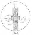
- FIG. 3 is a partial assembly cross section of the guiding member and positioning mechanism of the electronic apparatus of an embodiment of the invention;
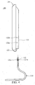
- FIG. 4 is a schematic view showing assembly of the electronic apparatus of an embodiment of the invention;
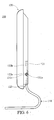
- FIG. 5 is a schematic view showing assembly following FIG. 4;
- FIG. 6 is a schematic view showing assembly following FIG. 5; and
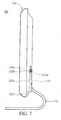
- FIG. 7 is a schematic view showing assembly following FIG. 6.
- Referring to FIG. 1 and FIG. 2, the
electronic apparatus 100 comprises apedestal 110, a main body (monitor) 120, and twopositioning mechanisms 130. Theelectronic apparatus 100 is, for example, a television. Although provided with twopositioning mechanisms 130, theelectronic apparatus 100 is not limited to having twopositioning mechanisms 130. Namely, theelectronic apparatus 100 may selectively comprise only onepositioning mechanism 130. - The
pedestal 110 comprises two opposing guidingmembers 111. Each guidingmember 111 comprises a first throughhole 112 and a second throughhole 113 coaxially connected to the first throughhole 112. In this embodiment, the diameter of the second throughhole 113 exceeds that of the first throughhole 112. Specifically, the diameters of the first throughhole 112 and second throughhole 113 can be designed as required. Namely, the diameter of the second throughhole 113 may be, alternatively, less than that of the first throughhole 112. Moreover, the profile of thepedestal 110 can be changed as required, and thepedestal 110 is not limited to having two opposing guidingmembers 111. Namely, thepedestal 110 may selectively comprise only one guidingmember 111. - The
main body 120 is detachably connected to the guidingmembers 111 of thepedestal 110. Specifically, themain body 120 comprises two guidinggrooves 121 corresponding to the guidingmembers 111. In this embodiment, the cross section of the guidinggrooves 121 is substantially the same as that of the guidingmembers 111. Additionally, each guidinggroove 121 comprises a plurality of positioning holes (122a, 122b) formed therein and located on different levels. Moreover, themain body 120 comprises two guiding slopedsurfaces 123 corresponding and connected to the guidinggrooves 121. Similarly, themain body 120 is not limited to having two guidinggrooves 121 and two guidingsloped surfaces 123. - Alternatively, the
main body 120 may selectively comprise only one guidinggroove 121 and only one guiding slopedsurface 123. - Moreover, when the
main body 120 is a monitor, the guidinggrooves 121 can be formed on the back of the monitor and a display panel (not shown) can be disposed on the front thereof. - Each
positioning mechanism 130 is movably disposed in each guidingmember 111 of thepedestal 110 and each guidinggroove 121 of themain body 120. Specifically, eachpositioning mechanism 130 comprises an engagingmember 131, aresilient member 132, and aretardant member 133. As shown in FIG. 2 and FIG. 3, theretardant member 133 covers and is fixed on the second throughhole 113 of the guidingmember 111. Additionally, theretardant member 133 comprises a third throughhole 133a coaxially connected to the second throughhole 113. The engagingmember 131 comprises apillar 131a, an abuttingportion 131b, and an engagingportion 131c. The abuttingportion 131b is between thepillar 131a and the engagingportion 131c and is disposed in the second throughhole 113. Thepillar 131a is disposed in the second throughhole 113 and third throughhole 133a of theretardant member 133 and extends outside the third throughhole 133a. The engagingportion 131c is disposed in the first throughhole 112 and extends outside the first throughhole 112. Theresilient member 132 is disposed in the second throughhole 113 and between the abuttingportion 131b of the engagingmember 131 and theretardant member 133. Specifically, theresilient member 132 is disposed at the periphery of thepillar 131a of the engagingmember 131. Accordingly, the engagingmember 131 of thepositioning mechanism 130 can move forward and backward, as indicated by arrow A of FIG. 3. - Moreover, the
resilient member 132 is, for example, a spring. - The following description is directed to assembly and disassembly of the electronic apparatus 100 (such as a television).
- When the main body (monitor) 120 is positioned on the
pedestal 110, as shown in FIG. 4, the guidinggrooves 121 of themain body 120 are respectively aimed at the guidingmembers 111 of thepedestal 110 and are moved downward (or relatively). As shown in FIG. 5, the guidingmembers 111 are simultaneously inserted into the corresponding guidinggrooves 121. At this point, the engagingportion 131c of each engagingmember 131 slides on each guiding slopedsurface 123 of themain body 120. Then, the engagingportions 131c and guidingmembers 111 simultaneously slide in the guidinggrooves 121. Because of the profiles of the guidinggrooves 121 and guidingmembers 111, the engagingportions 131c of the engagingmembers 131 are pushed into (the second throughholes 113 of) the guidingmembers 111. At this point, the abuttingportion 131b andpillar 131a of each engagingmember 131 move toward the third throughhole 133a, and theresilient member 132 disposed between the abuttingportion 131b and theretardant member 133 is compressed to provide resilience. Themain body 120 continues to move downward until the engagingportion 131c of each engagingmember 131 slide to thefirst positioning hole 122a in each guidinggroove 121. The engagingportion 131c rapidly ejects and engages thefirst positioning hole 122a by the resilience provided by theresilient member 132, as shown in FIG. 6. At this point, themain body 120 andpedestal 110 are completely assembled. - Moreover, when the height of the
main body 120 relative to thepedestal 110 is adjusted, the engaging member 131 (orpillar 131a) can be pulled outward to separate theengaging portion 131c from thefirst positioning hole 122a. At this point, theresilient member 132 disposed between the abuttingportion 131b and theretardant member 133 is compressed to again provide resilience. Themain body 120 is then moved downward and the engaging member 131 (orpillar 131a) is released. When the engagingportion 131c of each engagingmember 131 slides to thesecond positioning hole 122b in each guidinggroove 121, the engagingportion 131c rapidly ejects and engages thesecond positioning hole 122b by the resilience provided by theresilient member 132, as shown in FIG. 7. At this point, adjustment of the height of themain body 120 with respect to thepedestal 110 is complete. Specifically, theelectronic apparatus 100 ormain body 120 is not limited to having only twopositioning holes main body 120 may selectively comprise more positioning holes in each guidinggroove 121, enabling different adjustment of the height of themain body 120 with respect to thepedestal 110. - In another aspect, when the
main body 120 is separated from thepedestal 110, the engaging member 131 (orpillar 131a) can be pulled out of thefirst positioning hole 122a orsecond positioning hole 122b. Themain body 120 is then simultaneously moved upward (or relatively) until it is completely separated from thepedestal 110. - In conclusion, the
electronic apparatus 100 can be rapidly assembled and disassembled, and the height thereof can be easily adjusted. Moreover, theelectronic apparatus 100 can be rapidly assembled and disassembled in the absence of any assisting tool. Thus, troubles of missing of bolts are prevented. - While the invention has been described by way of example and in terms of preferred embodiment, it is to be understood that the invention is not limited thereto. To the contrary, it is intended to cover various modifications and similar arrangements (as would be apparent to those skilled in the art). Therefore, the scope of the appended claims should be accorded the broadest interpretation so as to encompass all such modifications and similar arrangements.
Claims (15)
- An electronic apparatus, comprising:a pedestal comprising a guiding member;a main body detachably connected to the guiding member and comprising a guiding groove in which the guiding member relatively slides; anda positioning mechanism movably disposed in the guiding member and guiding groove to control the sliding position of the guiding member with respect to the guiding groove.
- The electronic apparatus as claimed in claim 1, wherein the guiding member further comprises a first through hole, the guiding groove further comprises at least one positioning hole, and the positioning mechanism engages the positioning hole via the first through hole, controlling the sliding position of the guiding member with respect to the guiding groove.
- The electronic apparatus as claimed in claim 2, wherein the guiding member further comprises a second through hole, the positioning mechanism further comprises an engaging member, a resilient member, and a retardant member, the second through hole is coaxially connected to the first through hole, the engaging member is disposed in the first and second through holes, the retardant member covers and is fixed on the second through hole, and the resilient member is disposed in the second through hole and between the engaging member and the retardant member, providing resilience to the engaging member.
- The electronic apparatus as claimed in claim 3, wherein the retardant member further comprises a third through hole, the engaging member further comprises a pillar, an abutting portion, and an engaging portion, the third through hole is coaxially connected to the second through hole, the abutting portion is between the pillar and the engaging portion and is disposed in the second through hole, the pillar is disposed in the second and third through holes and extends outside the third through hole, the engaging portion is disposed in and extends outside the first through hole, engaging the positioning hole, and the resilient member is between the abutting portion and the retardant member and is disposed at the periphery of the pillar.
- The electronic apparatus as claimed in claim 4, wherein the main body further comprises a guiding sloped surface connected to the guiding groove, and the engaging portion engages the positioning hole by sliding on the guiding sloped surface and guiding groove.
- The electronic apparatus as claimed in claim 3, wherein the resilient member comprises a spring.
- The electronic apparatus as claimed in claim 1, wherein the cross sections of the guiding groove and guiding member are substantially the same.
- The electronic apparatus as claimed in claim 1, wherein the main body comprises a monitor.
- A television, comprising:a pedestal comprising a guiding member;a monitor detachably connected to the guiding member and comprising a guiding groove in which the guiding member relatively slides; anda positioning mechanism movably disposed in the guiding member and guiding groove to control the sliding position of the guiding member with respect to the guiding groove.
- The television as claimed in claim 9, wherein the guiding member further comprises a first through hole, the guiding groove further comprises at least one positioning hole, and the positioning mechanism engages the positioning hole via the first through hole, controlling the sliding position of the guiding member with respect to the guiding groove.
- The television as claimed in claim 10, wherein the guiding member further comprises a second through hole, the positioning mechanism further comprises an engaging member, a resilient member, and a retardant member, the second through hole is coaxially connected to the first through hole, the engaging member is disposed in the first and second through holes, the retardant member covers and is fixed on the second through hole, and the resilient member is disposed in the second through hole and between the engaging member and the retardant member, providing resilience to the engaging member.
- The television as claimed in claim 11, wherein the retardant member further comprises a third through hole, the engaging member further comprises a pillar, an abutting portion, and an engaging portion, the third through hole is coaxially connected to the second through hole, the abutting portion is between the pillar and the engaging- portion and is disposed in the second through hole, the pillar is disposed in the second and third through holes and extends outside the third through hole, the engaging portion is disposed in and extends outside the first through hole, engaging the positioning hole, and the resilient member is between the abutting portion and the retardant member and is disposed at the periphery of the pillar.
- The television as claimed in claim 12, wherein' the monitor further comprises a guiding sloped surface connected to the guiding groove, and the engaging portion engages the positioning hole by sliding on the guiding sloped surface and guiding groove.
- The television as claimed in claim 11, wherein the resilient member comprises a spring.
- The television as claimed in claim 9, wherein the cross sections of the guiding groove and guiding member are substantially the same.
Applications Claiming Priority (1)
| Application Number | Priority Date | Filing Date | Title |
|---|---|---|---|
| CNA2004101019764A CN1787625A (en) | 2004-12-10 | 2004-12-10 | Electronic device and TV structure |
Publications (3)
| Publication Number | Publication Date |
|---|---|
| EP1669661A2 true EP1669661A2 (en) | 2006-06-14 |
| EP1669661A3 EP1669661A3 (en) | 2007-01-03 |
| EP1669661B1 EP1669661B1 (en) | 2008-12-24 |
Family
ID=36129900
Family Applications (1)
| Application Number | Title | Priority Date | Filing Date |
|---|---|---|---|
| EP05025240A Expired - Lifetime EP1669661B1 (en) | 2004-12-10 | 2005-11-18 | Electronic apparatus |
Country Status (3)
| Country | Link |
|---|---|
| EP (1) | EP1669661B1 (en) |
| CN (1) | CN1787625A (en) |
| DE (1) | DE602005011920D1 (en) |
Cited By (1)
| Publication number | Priority date | Publication date | Assignee | Title |
|---|---|---|---|---|
| CN103093695A (en) * | 2011-11-08 | 2013-05-08 | 鸿富锦精密工业(深圳)有限公司 | Flat panel display |
Families Citing this family (1)
| Publication number | Priority date | Publication date | Assignee | Title |
|---|---|---|---|---|
| CN102829292A (en) * | 2011-06-15 | 2012-12-19 | 冠捷投资有限公司 | monitor stand |
Family Cites Families (6)
| Publication number | Priority date | Publication date | Assignee | Title |
|---|---|---|---|---|
| US2980456A (en) * | 1959-08-14 | 1961-04-18 | Earl L Mcmullin | Telescoping pole |
| US6016171A (en) * | 1998-03-27 | 2000-01-18 | Inventec Corporation | Height-adjustable case structure for the display of portable computers |
| JP2002160586A (en) * | 2000-11-27 | 2002-06-04 | Matsushita Electric Ind Co Ltd | Monitor mounting equipment |
| KR100443981B1 (en) * | 2001-12-04 | 2004-08-09 | 삼성전자주식회사 | Monitor |
| KR100770982B1 (en) * | 2003-02-21 | 2007-10-30 | 삼성전자주식회사 | Display device |
| TWI221954B (en) * | 2003-08-07 | 2004-10-11 | Benq Corp | Flat panel display |
-
2004
- 2004-12-10 CN CNA2004101019764A patent/CN1787625A/en active Pending
-
2005
- 2005-11-18 EP EP05025240A patent/EP1669661B1/en not_active Expired - Lifetime
- 2005-11-18 DE DE602005011920T patent/DE602005011920D1/en not_active Expired - Lifetime
Cited By (1)
| Publication number | Priority date | Publication date | Assignee | Title |
|---|---|---|---|---|
| CN103093695A (en) * | 2011-11-08 | 2013-05-08 | 鸿富锦精密工业(深圳)有限公司 | Flat panel display |
Also Published As
| Publication number | Publication date |
|---|---|
| CN1787625A (en) | 2006-06-14 |
| EP1669661B1 (en) | 2008-12-24 |
| EP1669661A3 (en) | 2007-01-03 |
| DE602005011920D1 (en) | 2009-02-05 |
Similar Documents
| Publication | Publication Date | Title |
|---|---|---|
| US20060208145A1 (en) | Electronic apparatus | |
| EP3398481B1 (en) | Slide rail assembly | |
| US9835398B2 (en) | Firearm trigger group module with pivoting element non-coaxial to assembly pin and method of installing a trigger group module | |
| US7260912B2 (en) | Gun barrel and trigger flashlight and/or laser mount structure | |
| US7611109B2 (en) | Electronic device hanging mechanism | |
| JP6337047B2 (en) | Drawer slide rail kit and mounting device | |
| US20020101139A1 (en) | Elevating device for planer displayer | |
| US9134592B2 (en) | Ceiling hanger | |
| US11598479B2 (en) | Display support structure | |
| US10244867B2 (en) | Slide rail mechanism and adjusting assembly for slide rail | |
| EP2713236B1 (en) | Display device with height adjustment structure and terminal having the same | |
| US8047490B2 (en) | Elevation rotating mechanism and display device using the same | |
| US10728639B1 (en) | Speaker mounting assembly | |
| EP1669661B1 (en) | Electronic apparatus | |
| DE10241132A1 (en) | Headrest for vehicles, aircraft and furniture, incorporates sound transmitter, sound receiver and lighting in adjustable side wings | |
| US7533857B2 (en) | Height-adjustable apparatus | |
| EP3363326A1 (en) | Drawer panel adjusting device | |
| EP3598858B1 (en) | Connection device | |
| JP2006106046A (en) | Connector and video display device | |
| US7403376B2 (en) | Automatic stabilizing device for a display | |
| US7129997B1 (en) | Monitor case comprising facile detach structure | |
| EP3603450A1 (en) | Adjustment mechanism | |
| WO2006084052A3 (en) | Decorative computer monitor frame | |
| KR100296283B1 (en) | Device for adjusting height of display monitor | |
| EP4174889B1 (en) | Illuminated electrical installation device such as a switch or button |
Legal Events
| Date | Code | Title | Description |
|---|---|---|---|
| PUAI | Public reference made under article 153(3) epc to a published international application that has entered the european phase |
Free format text: ORIGINAL CODE: 0009012 |
|
| AK | Designated contracting states |
Kind code of ref document: A2 Designated state(s): AT BE BG CH CY CZ DE DK EE ES FI FR GB GR HU IE IS IT LI LT LU LV MC NL PL PT RO SE SI SK TR |
|
| AX | Request for extension of the european patent |
Extension state: AL BA HR MK YU |
|
| PUAL | Search report despatched |
Free format text: ORIGINAL CODE: 0009013 |
|
| AK | Designated contracting states |
Kind code of ref document: A3 Designated state(s): AT BE BG CH CY CZ DE DK EE ES FI FR GB GR HU IE IS IT LI LT LU LV MC NL PL PT RO SE SI SK TR |
|
| AX | Request for extension of the european patent |
Extension state: AL BA HR MK YU |
|
| 17P | Request for examination filed |
Effective date: 20070612 |
|
| AKX | Designation fees paid |
Designated state(s): DE FR GB |
|
| GRAP | Despatch of communication of intention to grant a patent |
Free format text: ORIGINAL CODE: EPIDOSNIGR1 |
|
| GRAS | Grant fee paid |
Free format text: ORIGINAL CODE: EPIDOSNIGR3 |
|
| GRAA | (expected) grant |
Free format text: ORIGINAL CODE: 0009210 |
|
| RIN1 | Information on inventor provided before grant (corrected) |
Inventor name: CHEN, YI-JEN |
|
| AK | Designated contracting states |
Kind code of ref document: B1 Designated state(s): DE FR GB |
|
| REG | Reference to a national code |
Ref country code: GB Ref legal event code: FG4D |
|
| REF | Corresponds to: |
Ref document number: 602005011920 Country of ref document: DE Date of ref document: 20090205 Kind code of ref document: P |
|
| PLBE | No opposition filed within time limit |
Free format text: ORIGINAL CODE: 0009261 |
|
| STAA | Information on the status of an ep patent application or granted ep patent |
Free format text: STATUS: NO OPPOSITION FILED WITHIN TIME LIMIT |
|
| 26N | No opposition filed |
Effective date: 20090925 |
|
| REG | Reference to a national code |
Ref country code: FR Ref legal event code: PLFP Year of fee payment: 12 |
|
| REG | Reference to a national code |
Ref country code: FR Ref legal event code: PLFP Year of fee payment: 13 |
|
| REG | Reference to a national code |
Ref country code: FR Ref legal event code: PLFP Year of fee payment: 14 |
|
| P01 | Opt-out of the competence of the unified patent court (upc) registered |
Effective date: 20230428 |
|
| PGFP | Annual fee paid to national office [announced via postgrant information from national office to epo] |
Ref country code: GB Payment date: 20240902 Year of fee payment: 20 |
|
| PGFP | Annual fee paid to national office [announced via postgrant information from national office to epo] |
Ref country code: FR Payment date: 20240829 Year of fee payment: 20 |
|
| PGFP | Annual fee paid to national office [announced via postgrant information from national office to epo] |
Ref country code: DE Payment date: 20240822 Year of fee payment: 20 |
|
| REG | Reference to a national code |
Ref country code: DE Ref legal event code: R071 Ref document number: 602005011920 Country of ref document: DE |
|
| REG | Reference to a national code |
Ref country code: GB Ref legal event code: PE20 Expiry date: 20251117 |