EP1669649A1 - Fluid control valve with angled seal - Google Patents
Fluid control valve with angled seal Download PDFInfo
- Publication number
- EP1669649A1 EP1669649A1 EP20050026947 EP05026947A EP1669649A1 EP 1669649 A1 EP1669649 A1 EP 1669649A1 EP 20050026947 EP20050026947 EP 20050026947 EP 05026947 A EP05026947 A EP 05026947A EP 1669649 A1 EP1669649 A1 EP 1669649A1
- Authority
- EP
- European Patent Office
- Prior art keywords
- valve
- pressure control
- port
- fluid control
- outlet port
- Prior art date
- Legal status (The legal status is an assumption and is not a legal conclusion. Google has not performed a legal analysis and makes no representation as to the accuracy of the status listed.)
- Withdrawn
Links
- 239000012530 fluid Substances 0.000 title claims abstract description 106
- 238000000034 method Methods 0.000 claims abstract description 5
- 238000004806 packaging method and process Methods 0.000 claims description 16
- 230000005540 biological transmission Effects 0.000 claims description 10
- 230000000712 assembly Effects 0.000 abstract description 9
- 238000000429 assembly Methods 0.000 abstract description 9
- 230000004907 flux Effects 0.000 description 8
- 230000009467 reduction Effects 0.000 description 6
- 239000000463 material Substances 0.000 description 4
- 238000004519 manufacturing process Methods 0.000 description 3
- 230000007246 mechanism Effects 0.000 description 3
- 230000008859 change Effects 0.000 description 2
- 238000004891 communication Methods 0.000 description 2
- 230000000670 limiting effect Effects 0.000 description 2
- 230000002829 reductive effect Effects 0.000 description 2
- 230000004044 response Effects 0.000 description 2
- 244000043261 Hevea brasiliensis Species 0.000 description 1
- 229920000459 Nitrile rubber Polymers 0.000 description 1
- 230000009471 action Effects 0.000 description 1
- 230000004075 alteration Effects 0.000 description 1
- 230000009286 beneficial effect Effects 0.000 description 1
- 230000008901 benefit Effects 0.000 description 1
- -1 but not limited to Substances 0.000 description 1
- 229920005549 butyl rubber Polymers 0.000 description 1
- 230000000052 comparative effect Effects 0.000 description 1
- 230000002860 competitive effect Effects 0.000 description 1
- 230000003247 decreasing effect Effects 0.000 description 1
- 230000001627 detrimental effect Effects 0.000 description 1
- 230000000694 effects Effects 0.000 description 1
- 238000005516 engineering process Methods 0.000 description 1
- 238000002955 isolation Methods 0.000 description 1
- 230000004048 modification Effects 0.000 description 1
- 238000012986 modification Methods 0.000 description 1
- 229920003052 natural elastomer Polymers 0.000 description 1
- 229920001194 natural rubber Polymers 0.000 description 1
- 230000037361 pathway Effects 0.000 description 1
- 239000004033 plastic Substances 0.000 description 1
- 230000002265 prevention Effects 0.000 description 1
- 230000000717 retained effect Effects 0.000 description 1
- 229920002379 silicone rubber Polymers 0.000 description 1
- 239000004945 silicone rubber Substances 0.000 description 1
- 229920003051 synthetic elastomer Polymers 0.000 description 1
- 239000005061 synthetic rubber Substances 0.000 description 1
- XLYOFNOQVPJJNP-UHFFFAOYSA-N water Substances O XLYOFNOQVPJJNP-UHFFFAOYSA-N 0.000 description 1
Images



Classifications
-
- F—MECHANICAL ENGINEERING; LIGHTING; HEATING; WEAPONS; BLASTING
- F16—ENGINEERING ELEMENTS AND UNITS; GENERAL MEASURES FOR PRODUCING AND MAINTAINING EFFECTIVE FUNCTIONING OF MACHINES OR INSTALLATIONS; THERMAL INSULATION IN GENERAL
- F16K—VALVES; TAPS; COCKS; ACTUATING-FLOATS; DEVICES FOR VENTING OR AERATING
- F16K31/00—Actuating devices; Operating means; Releasing devices
- F16K31/02—Actuating devices; Operating means; Releasing devices electric; magnetic
- F16K31/06—Actuating devices; Operating means; Releasing devices electric; magnetic using a magnet, e.g. diaphragm valves, cutting off by means of a liquid
- F16K31/0603—Multiple-way valves
- F16K31/0624—Lift valves
- F16K31/0627—Lift valves with movable valve member positioned between seats
- F16K31/0631—Lift valves with movable valve member positioned between seats with ball shaped valve members
-
- Y—GENERAL TAGGING OF NEW TECHNOLOGICAL DEVELOPMENTS; GENERAL TAGGING OF CROSS-SECTIONAL TECHNOLOGIES SPANNING OVER SEVERAL SECTIONS OF THE IPC; TECHNICAL SUBJECTS COVERED BY FORMER USPC CROSS-REFERENCE ART COLLECTIONS [XRACs] AND DIGESTS
- Y10—TECHNICAL SUBJECTS COVERED BY FORMER USPC
- Y10T—TECHNICAL SUBJECTS COVERED BY FORMER US CLASSIFICATION
- Y10T137/00—Fluid handling
- Y10T137/8593—Systems
- Y10T137/86493—Multi-way valve unit
- Y10T137/86574—Supply and exhaust
- Y10T137/86622—Motor-operated
Definitions
- the present disclosure relates to fluid control valves and seals associated therewith.
- valves are used to control a variety of fluids and in a variety of ways.
- fluid flow is controlled in one or more of a variety of ways.
- Pulse-width-modulated, on/off, and variable pressure a re a few coined manners of controlling fluid flow known to those of skill in the art.
- solenoid (i.e ., electrically actuated) valves that include electrical systems are often used due to their ability to efficiently and effectively control fluid flow in a variety of ways.
- Solenoid valves are used in many applications.
- solenoid valves are useful in controlling the flow of hydraulic fluid in, for example, automatic transmission systems of motor vehicles.
- shifting of transmission speed ratios is controlled by an electronic controller that provides an electrical signal to the solenoid valve, which then provides a corresponding fluid pressure signal to a pressure responsive actuator for effecting a desired transmission speed ratio change.
- solenoid valves typically include at least a supply port (also referred to as an "inlet port”) and a pressure control output port, which provide respective fluid flow to and from a valves housing for operation of an external component in communication therewith.
- a supply port also referred to as an "inlet port”
- a pressure control output port which provide respective fluid flow to and from a valves housing for operation of an external component in communication therewith.
- the internal valve mechanics of solenoid valves vary widely within the valve housing.
- solenoid valve comprises a ball valve having an inlet port, a pressure control outlet port, and an exhaust port through which fluid is discharged to a sump or is returned to rejoin the fluid supply.
- Such valves provide electrical control of a fluid pressure by controlling the flow of fluid from the inlet port to a valving chamber within the valve housing.
- the valving chamber in such valves is in communication with the pressure control outlet port.
- a desired pressure at the pressure control outlet port is maintained by controlling the amount of fluid bleed to the exhaust port.
- ball valves include a ball disposed in the valving chamber, whereby the ball moves with respect to a valve seat that's adjacent the inlet port.
- Ball valves can provide many advantages over standard solenoid valves, some of which include, for example, higher permissible flow rates, lower resistance to flow resulting in a lower pressure drop across a valve, higher permissible pressure ratings, compatibility with a wide range of media, no minimum pressure requirements (differential pressure), and smoother operation (reducing water hammer).
- exhaust and pressure control outlet ports of fluid control valves are generally defined in isolation by a seal that is interposed between openings to the two ports on the outer surface of a solenoid valve.
- a seal is formed by horizontally stacking installed "o"-rings around the valve housing.
- Such an arrangement defines isolated ports into and out of the valve housing.
- vertical space required by the valve assembly includes the vertical space accommodating a supported o-ring adjacent to the exhaust port, and the vertical space accommodating a supported o-ring adjacent to the pressure control outlet port.
- Each o-ring is conventionally supported by associated grooves and similar structures defined within a valve housing outer surface, all of which increase vertical packaging space requirements of such valves.
- a method of the invention comprises reducing vertical packaging space requirements associated with an assembly utilizing one or more fluid control valves by replacing one or more fluid control valves of the assembly with a corresponding number of fluid control valves of the invention.
- the fluid control valves of the assembly lack an angled seal between exterior openings of the pressure control outlet port and the exhaust port.
- a fluid control valve comprises an inlet port; a pressure control outlet port; an exhaust port; and an angled seal, wherein the seal is angled between the pressure control outlet port and the exhaust port external to body of the valve.
- the angled seal comprises any suitable material such as, for example, an o-ring.
- fluid control valves of the invention comprise an annular groove for receipt of the angled seal.
- fluid control valves of the invention comprises multiple openings associated with at least one of the pressure control outlet port and the exhaust port extend circumferentially around only about one-half of the circumference of the valve.
- multiple openings associated with the pressure control outlet port and multiple openings associated with the exhaust port can be positioned on opposite sides of the angled seal.
- an opening associated with the pressure control outlet port and an opening associated with the exhaust port are positioned on opposite sides of the angled seal.
- the inlet port of fluid control valves of the invention comprises multiple openings exterior to the valve.
- the pressure control outlet port of fluid control valves of the invention comprises multiple openings exterior to the valve.
- the exhaust port of fluid control valves of the invention comprises multiple openings exterior to the valve.
- Valve assemblies included within the invention include, but are not limited to, ball valves and spool valves.
- An exemplary valve assembly of the invention comprises a pressure control outlet port; an exhaust port; and a seal disposed at an angle exterior to the valve and between exterior openings of the pressure control outlet port and the exhaust port.
- the pressure control outlet port and the exhaust port are vertically spaced at a minimal distance that prevents openings of the pressure control outlet port and the exhaust port from vertically overlapping with respect to a vertical axis through the valve.
- the seal vertically overlaps with at least one of the pressure control outlet port or exhaust port openings with respect to a vertical axis through the valve.
- the seal can vertically overlaps with both of the pressure control outlet port and exhaust port openings with respect to a vertical axis through the valve.
- an exemplary fluid control valve of the invention comprises a solenoid operating assembly.
- a solenoid ball valve of the invention comprises an inlet port; a pressure control outlet port; an exhaust port; and an angled seal, wherein the seal is angled between the pressure control outlet port and the exhaust port external to body of the valve.
- Fluid control valves and valve assemblies of the invention are useful in a variety of applications.
- One particular application involves the automotive industry.
- an automatic transmission system for a motorized vehicle comprises at least one fluid control valve of the invention in one application.
- the fluid control valve can provide fluid pressure to a pressure responsive actuator for effecting transmission speed ratio change.
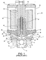
- FIG. 1 is a cross-section view of a prior art solenoid fluid control valve assembly.
- FIG. 2A is a cross-section view of an improved disclosed fluid control valve assembly, illustrated in a closed position.
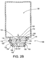
- FIG. 2B is a cross-section view of the fluid control valve assembly of FIG. 2A, illustrated in an open position.
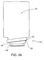
- FIG. 3A is an exterior view of the fluid control valve assembly of FIGS. 2A and 2B.
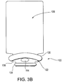
- FIG. 3B is an exterior view of the fluid control valve assembly of FIGS. 2A and 2B, viewed perpendicular to the cross-sectional view of FIGS. 2A and 2B and from the side of the valve assembly, having an exterior pressure control outlet port opening.
- FIG. 3C is an exterior view of the fluid control valve assembly of FIGS. 2A and 2B, viewed perpendicular to the cross-sectional view of FIGS. 2A and 2B and from the side of the valve assembly, having an exterior exhaust port opening.
- FIG. 4A is an exterior view of a further embodiment of a fluid control valve assembly of FIGS. 2A and 2B, viewed perpendicular to the cross-sectional view of FIGS. 2A and 2B and from the side of the valve assembly, having multiple exterior pressure control outlet port openings.
- FIG. 4B is an exterior view of the fluid control valve assembly of FIG. 4A, viewed perpendicular to the cross-sectional view of FIGS. 2A and 2B and from the side of the valve assembly, having multiple exhaust port openings.
- FIGURE 1 shows a prior art fluid control valve.
- many variations in types of fluid control valves, as well as components included therein and associated geometries, are known. It is not necessary to the practice of the present disclosed fluid control valve, or for understanding of comparative background technology to provide further details about such variations, as one of ordinary skill in the fluid control valve arts can adapt the present disclosure for use with any suitable fluid control valve according to known principles and apparatus.
- fluid control valves generally include at least two ports, and more typically at least three ports, each with one or more external openings.
- valve assembly 1 includes an inlet port 6 isolated from other valve ports by a resilient seal ring 8 disposed in an annular groove 10 formed in an outer surface of a valve body 12.
- the inlet port 6 selectively facilitates fluid flow into an adjacent enlarged diameter bore 14 during operation based on opening and closing of inlet port 6 by respective upward and downward movement of a ball 16 within the valve.
- the bore 14 provides a passageway within the valve assembly 1 for selective fluid flow between two or more of inlet port 6, pressure control outlet port 18 (i.e., the port through which fluid is discharged to at least one operatively connected component that is at least partially controlled by the solenoid ball valve), and the exhaust port 20 ( i.e ., the port through which fluid is discharged to a sump or is returned to rejoin the fluid supply).
- the valve assembly 1 is capable of averting or limiting fluid flow to the exhaust port 20 by selective seating of the ball 16 against flanged exhaust seats 22 extending within the bore 14.
- the pressure control outlet port 18 is isolated from the exhaust port 20 and the inlet port 6 by a pair of resilient seal rings 24, 26.
- the seal rings 24, 26 are disposed in a spaced relationship on opposite sides of the pressure control outlet port 18 and in annular grooves 28, 30 formed in an outer surface of the valve body 12.
- multiple openings typically associated with the pressure control outlet port 18 and the exhaust port 20 are isolated from each other external to the valve body 12. Owing to this configuration, fluid flow is permitted to flow only internally to the valve assembly 1 in a controlled manner based on the positioning of the ball 16 within bore 14.
- the pressure control outlet port 18 includes multiple openings extending circumferentially a round the valve body 12 for se lective egress of fluid from the valve assembly 1.
- the exhaust port 20 conventionally includes multiple openings extending circumferentially around the valve body 12 for selective egress of fluid from the valve assembly 1.
- Multiple openings associated with each port are typically spaced approximately equidistant from each other around the entire circumference of a fluid control valve.
- each port typically includes two openings spaced horizontally 180 degrees apart around the circumference with respect to a vertical axis extending through the valve, as shown in the configuration illustrated in FIG. 1.
- more than two circumferentially spaced openings are typical for each type of port (e.g., the pressure control outlet port 18 and the exhaust port 20). While only one opening for the inlet port 6 is illustrated in FIG. 1, it is known that the inlet port 6 can also include more than one opening, all of which facilitate the selective flow of fluid into the valve assembly 1.
- a solenoid operating assembly indicated generally at 34 controls movement of the ball 16.
- the solenoid operating assembly 34 typically includes a coil bobbin 36 with coil wound thereon and received over a lower flux ring 40 (also known as a "flux collector”) attached to an upper end of the valve body 12.
- An upper flux ring 42 (also known as a "flux collector”) rests above upper end of bobbin 36.
- the flux rings 40, 42 and the bobbin 36 are retained adjacent the valve body 12 as an operating assembly encompassed by an outer casing 44.
- a moveable armature 46 containing an armature spring 47 is slidably disposed within the upper end of the lower flux ring 40.
- a working air gap is defined between poll piece 50 and the moveable armature 46.
- An operating rod 48 is received through the armature 46, secured thereto for movement therewith.
- the operating rod 48 extends downwardly through the lower flux ring 40.
- the operating rod 48 extends down into the bore 14 of the valve assembly 1.
- the lower end of the operating rod 48 operatively engages the ball 16 during operation.
- the normally closed valve assembly 6 shown in FIG. 1 includes a ball 16 sealably seated against the valve housing 12 with a solenoid operator 34 d e-energized.
- the pressure control outlet port 18 is open to the exhaust port 20, and thus no pressure signal is provided at the port 16.
- the arrangement of the flux rings 40, 42 is such that a pole piece 50 attracts the armature 46.
- the armature 46 thereby moves up such that the ball 16 moves progressively away from its seated position at the inlet port 6 and closer to the flanged exhaust seats 22.
- This movement of the ball 16 reduces or eliminates the flow of fluid to the exhaust port 20 and thereby increases pressure to the pressure control outlet port 18.
- the armature 46 moves down to return the ball 16 to a seated position adjacent the inlet port 6.
- FIG. 2A and FIG. 2B an exemplary embodiment of a valve assembly 100 of the present disclosed fluid control valve is illustrated. Note that components similar to those referenced in the embodiment of FIGS. 2A and 2B may be denoted by the same reference number in a later figure in order to highlight corresponding parts and minimize duplication in the description. Utilizing this format, although they may be identified in later figures, certain components may be described only once with reference to the first figure in which they are shown.
- the valve assembly 100 includes an inlet port 102 that is isolated from other valve ports by a resilient seal ring 104 disposed in annular groove 106 formed in an outer surface of the valve body 108.
- the inlet port 102 selectively facilitates fluid flow into an adjacent enlarged diameter bore 110 based on the opening and closing of the inlet port 102 by respective upward and downward movement of the ball 112.
- the bore 110 provides a passageway within the valve assembly 100 for selective fluid flow between two or more of the inlet port 102, a pressure control outlet port 114 (i.e., the port through which fluid is discharged to at least one operatively connected component that is at least partially controlled by the valve), and an exhaust port 116 (i.e., the port through which fluid is discharged to a sump or is returned to rejoin the fluid supply).
- the valve assembly 100 is capable of averting or limiting fluid flow to the exhaust port 116 by selective seating of the ball 112 against flanged exhaust seats 118 of the valve housing 108 that extend within the bore 110.
- the pressure control outlet port 114 is isolated from the exhaust port 116 and the inlet port 102 by a single resilient seal ring 120 disposed in a similarly angled annular groove 122.
- the seal ring 120 provides an angled seal between the pressure control outlet p ort 114 and the exhaust port 116 around an outer surface of the valve body 108.
- Use of the term "angled" throughout is in reference to a vertical plane extending longitudinally through the valve assembly 100 (i.e., from the inlet port 102 upward through the operating assembly 126 illustrated in FIGS. 2A and 2B) and a horizontal plane orthogonal thereto.
- FIGS. 3A-3C An exterior appearance of the valve assembly 100 is illustrated generally in FIGS. 3A-3C.
- FIG. 3A illustrates the exterior of valve assembly 100 as taken from the same side of the valve assembly 100 as that illustrated in cross-section in FIGS. 2A and 2B.
- FIG. 3B illustrates the exterior of the valve assembly 100 taken from a view that is perpendicular to that shown in FIG. 3A, specifically, as viewed from the side of the valve assembly 100 having the pressure control outlet port 114 opening extending therefrom.
- FIG. 3C is a view perpendicular to that shown in FIG. 3A, as viewed from the side of the valve assembly 100 having the exhaust port 116 opening extending therefrom.
- the seal ring 120 and associated annular groove 122 are angled with respect to their conventional horizontal positioning around an exterior surface of the valve housing 108.
- vertically s paced openings associated with the pressure control outlet port 114 and the exhaust port 116 are isolated from each other external to the valve body 108, such that fluid flow is permitted only internal to the valve assembly 100, and in a controlled manner, based upon positioning of the ball 112, or other suitable valve closure mechanism within the bore 110, or other suitable fluid pathway.
- Vertical spacing between the openings of the pressure control outlet port 114 and the exhaust port 116 is often necessitated and dictated by the internal mechanics and structure of a fluid control valve.
- the seal ring 120 overlaps with at least one of the pressure control outlet port 114 or the exhaust port 116 openings in relation to a vertical axis through the valve 100.
- the seal ring 120 overlaps with both the pressure control outlet port 114 and the exhaust port 116 openings in relation to a vertical axis through the valve.
- the seal ring 120 between the pressure control outlet port 114 and the exhaust port 116 is angled with respect to the seal ring 104 adjacent the inlet port 102. It is to be understood, however, that more than one seal ring within the valve can be angled. For example, when the inlet port 102 includes one or more circumferentially positioned openings, a se al r ing between the inlet p ort and the pressure control outlet port 114 may optionally be angled. Although vertical packaging space requirements may not be decreased to the extent made possible by use of only one angled seal ring positioned between the pressure control outlet port 114 and the exhaust port 116, more than one angled seal ring may also be positioned between the pressure control outlet port 114 and the exhaust port 116. If multiple seal rings within a valve are angled, they need not be angled by the same degree. For maximum vertical packaging space reduction, however, it is desirable to position all angled seal rings at the same relative degree of angle with respect to vertical and horizontal planes extending through the valve.
- the angles at which the seal ring 120 and associated annular groove 122 are positioned can vary depending on the desired effect, as well as internal mechanics of the valve assembly 100, and the dimensions of the individual valve assembly 100 components (e.g., the pressure control outlet port 114, the exhaust port 116, the ball 112, the seal ring 1 20, and other valve components).
- each of the individual valve ports within a fluid control valve may include multiple openings exterior to the valve housing 108.
- multiple openings associated with the pressure control outlet port 114 and the exhaust port 116 extend circumferentially around only about one-half of the circumference of the valve body 108 due to the angled positioning of the resilient seal ring 120 between the pressure control outlet port 114 and the exhaust port 116.
- FIGS. 4A and 4B illustrate an exterior surface of a further embodiment of the disclosed valve, whereby multiple openings are provided for each of the pressure control outlet port 114 and the exhaust port 116. While only one opening for the inlet port 102 is illustrated in FIGS. 2A and 2B, the inlet port 102 can also comprise more than one opening, all of which provide selective flow of fluid into the valve assembly 100.
- Operatively engaging the ball 112 is a rod 124 coupled to any suitable operating assembly generally shown in FIGS. 2A and 2B as 126.
- the operating assembly 126 comprises a solenoid operator such as that described with reference to FIG. 1.
- any suitable operating mechanism can be used with the disclosed improved valve assemblies.
- the seal ring 120 fits within a rectangular-shaped annular groove 122. In another embodiment, the seal ring 120 fits within a semicylindrical annual groove 122. Variations in dimension and shape of the annular groove 122 fall within the scope of the invention.
- the annular groove 122 may have varying depths as it extends around the circumference of the valve assembly 100. Further, the annular groove 122 may be discontinuous, or lack symmetry, in extending around the circumference of the valve assembly 100. Any convenient annular groove, or similar structure, can be used to maintain the seal ring 120 at a desired angle and position along the outside of the valve housing 108. Such variations fall within the scope of the present invention.
- the seal ring 120 can be made from any suitable material.
- the seal ring 120 can be made from materials including, but not limited to, synthetic rubbers and natural rubbers.
- synthetic rubbers and natural rubbers For example, buna-N, silicone rubber, and butyl rubber are two generally suitable materials for manufacturing the seal ring 120.
- any suitable seal can be used to reliably isolate the exhaust port 116 and the pressure control outlet port 114 external to the valve housing 108.
- any seal that reliably prevents leaking between the exhaust port 116 and the pressure control outlet port 114 can function as the seal ring 120, whether or not it is shaped as a continuous ring.
- the seal ring 120 comprises an O-ring. It is well known to those of ordinary skill in the art that O-rings impart compliancy and resiliency in a seal. Thus, manufacturing tolerances need not be as stringent when using O-rings as compared to when using other seals that are less compliant and resilient. This provides even greater flexibility in the design and manufacture of improved fluid control valves utilizing seals of the present disclosure.
- valve assemblies include, but are not limited to, normally closed (i.e., valve assemblies wherein essentially no fluid flow exits the valve assembly via the pressure control outlet port, whether or not fluid flow is allowed into the valve assembly via the inlet port) and normally open (i.e ., valve assemblies wherein fluid flows into and through the valve assembly via the inlet port and from which fluid flows from the valve assembly via the pressure control outlet port valve assemblies).
- FIGS. 2A and 2B An exemplary "normally closed” improved valve assembly 100 is shown in FIGS. 2A and 2B.
- the normally closed valve assembly 100 includes the ball 112 sealably seated against the valve housing 108 with the operating assembly 126 in its normal state whereby the rod 124 and the ball 112 are situated in their lower most position within the bore 118 as illustrated in FIG. 2A.
- the pressure control outlet port 114 In this normal state, where the inlet port 102 is closed, the pressure control outlet port 114 is open to the exhaust port 116; thus, no pressure signal is provided at the port 114.
- the rod 124 moves upward such that the ball 112 moves progressively away from its seated position at the inlet port 102 and closer to the exhaust seats 118.
- the presently disclosed improved valves are advantageously used in many applications.
- the improved valves provide significant reductions in packaging space requirements, particularly those associated with vehicle packaging space. These reductions in packaging space are particularly beneficial when the valves are used in the automobile (and other motorized vehicle) industrial segment.
- Many subassemblies within motorized vehicles utilize multiple valves for control of many types of fluids therein.
- one such subassembly is an automatic transmission system.
- Multiple valves are used in automatic transmission systems to provide a fluid pressure signal to a pressure responsive actuator in response to, e.g., an electric signal for effecting desired transmission speed ratio changes.
Landscapes
- Engineering & Computer Science (AREA)
- General Engineering & Computer Science (AREA)
- Mechanical Engineering (AREA)
- Magnetically Actuated Valves (AREA)
- Valve Housings (AREA)
Abstract
Description
- The present disclosure relates to fluid control valves and seals associated therewith.
- Many different types of valves are used to control a variety of fluids and in a variety of ways. Depending on the application, fluid flow is controlled in one or more of a variety of ways. Pulse-width-modulated, on/off, and variable pressure a re a few coined manners of controlling fluid flow known to those of skill in the art. To assist in control of fluid flow, solenoid (i.e., electrically actuated) valves that include electrical systems are often used due to their ability to efficiently and effectively control fluid flow in a variety of ways.
- Solenoid valves are used in many applications. For example, solenoid valves are useful in controlling the flow of hydraulic fluid in, for example, automatic transmission systems of motor vehicles. In automatic transmission systems, shifting of transmission speed ratios is controlled by an electronic controller that provides an electrical signal to the solenoid valve, which then provides a corresponding fluid pressure signal to a pressure responsive actuator for effecting a desired transmission speed ratio change.
- Generally, solenoid valves typically include at least a supply port (also referred to as an "inlet port") and a pressure control output port, which provide respective fluid flow to and from a valves housing for operation of an external component in communication therewith. The internal valve mechanics of solenoid valves vary widely within the valve housing.
- One particular type of solenoid valve comprises a ball valve having an inlet port, a pressure control outlet port, and an exhaust port through which fluid is discharged to a sump or is returned to rejoin the fluid supply. Such valves provide electrical control of a fluid pressure by controlling the flow of fluid from the inlet port to a valving chamber within the valve housing. The valving chamber in such valves is in communication with the pressure control outlet port. A desired pressure at the pressure control outlet port is maintained by controlling the amount of fluid bleed to the exhaust port. Implicitly, ball valves include a ball disposed in the valving chamber, whereby the ball moves with respect to a valve seat that's adjacent the inlet port. The ball moves via an operating rod mechanism disposed between the ball and a solenoid armature operating in response to an electric signal. In this arrangement, two electrical circuits are typically used - one for opening the valve, and one for closing the valve. Ball valves can provide many advantages over standard solenoid valves, some of which include, for example, higher permissible flow rates, lower resistance to flow resulting in a lower pressure drop across a valve, higher permissible pressure ratings, compatibility with a wide range of media, no minimum pressure requirements (differential pressure), and smoother operation (reducing water hammer).
- No matter what type of internal valve mechanics are arranged within the valve housing, exhaust and pressure control outlet ports of fluid control valves, such as solenoid valves, are generally defined in isolation by a seal that is interposed between openings to the two ports on the outer surface of a solenoid valve. Conventionally, such a seal is formed by horizontally stacking installed "o"-rings around the valve housing. Such an arrangement defines isolated ports into and out of the valve housing. When o-rings are stacked in this conventional manner, vertical space required by the valve assembly includes the vertical space accommodating a supported o-ring adjacent to the exhaust port, and the vertical space accommodating a supported o-ring adjacent to the pressure control outlet port. Each o-ring is conventionally supported by associated grooves and similar structures defined within a valve housing outer surface, all of which increase vertical packaging space requirements of such valves.
- As consumer-driven demands for tighter packaging and miniaturization of components increases, it is desirable to decrease packaging space requirements of individual components within an overall assembly in order to reduce the size and weight of the assembly. Consumer demands influence, for example, the highly competitive automobile industrial segment. Assembled automobiles and other motorized vehicles typically include multiple solenoid valves, each of which contributes to overall packaging space requirements. T hus, reduction of packaging s pace requirements associated with valves including, for example, solenoid valves is particularly desirable and furthers meeting consumer demands.
- The present invention facilitates reduced vertical packaging space requirements by use of an angled seal in a fluid control valve. A method of the invention comprises reducing vertical packaging space requirements associated with an assembly utilizing one or more fluid control valves by replacing one or more fluid control valves of the assembly with a corresponding number of fluid control valves of the invention. In this method, the fluid control valves of the assembly lack an angled seal between exterior openings of the pressure control outlet port and the exhaust port.
- According to one embodiment of the invention, a fluid control valve comprises an inlet port; a pressure control outlet port; an exhaust port; and an angled seal, wherein the seal is angled between the pressure control outlet port and the exhaust port external to body of the valve. The angled seal comprises any suitable material such as, for example, an o-ring. In a further embodiment, fluid control valves of the invention comprise an annular groove for receipt of the angled seal.
- In yet a further embodiment, fluid control valves of the invention comprises multiple openings associated with at least one of the pressure control outlet port and the exhaust port extend circumferentially around only about one-half of the circumference of the valve. For example, multiple openings associated with the pressure control outlet port and multiple openings associated with the exhaust port can be positioned on opposite sides of the angled seal. In another example, an opening associated with the pressure control outlet port and an opening associated with the exhaust port are positioned on opposite sides of the angled seal.
- In still a further embodiment, the inlet port of fluid control valves of the invention comprises multiple openings exterior to the valve. Similarly, according to another embodiment, the pressure control outlet port of fluid control valves of the invention comprises multiple openings exterior to the valve. Likewise, according to another embodiment, the exhaust port of fluid control valves of the invention comprises multiple openings exterior to the valve.
- Valve assemblies included within the invention include, but are not limited to, ball valves and spool valves. An exemplary valve assembly of the invention comprises a pressure control outlet port; an exhaust port; and a seal disposed at an angle exterior to the valve and between exterior openings of the pressure control outlet port and the exhaust port. According to one aspect of this embodiment, the pressure control outlet port and the exhaust port are vertically spaced at a minimal distance that prevents openings of the pressure control outlet port and the exhaust port from vertically overlapping with respect to a vertical axis through the valve. According to another aspect of this embodiment, the seal vertically overlaps with at least one of the pressure control outlet port or exhaust port openings with respect to a vertical axis through the valve. As an example, the seal can vertically overlaps with both of the pressure control outlet port and exhaust port openings with respect to a vertical axis through the valve.
- Although not limited to solenoid valves, an exemplary fluid control valve of the invention comprises a solenoid operating assembly. For example, a solenoid ball valve of the invention comprises an inlet port; a pressure control outlet port; an exhaust port; and an angled seal, wherein the seal is angled between the pressure control outlet port and the exhaust port external to body of the valve.
- Fluid control valves and valve assemblies of the invention are useful in a variety of applications. One particular application involves the automotive industry. For example, an automatic transmission system for a motorized vehicle comprises at least one fluid control valve of the invention in one application. In this embodiment, the fluid control valve can provide fluid pressure to a pressure responsive actuator for effecting transmission speed ratio change.
- FIG. 1 is a cross-section view of a prior art solenoid fluid control valve assembly.
- FIG. 2A is a cross-section view of an improved disclosed fluid control valve assembly, illustrated in a closed position.
- FIG. 2B is a cross-section view of the fluid control valve assembly of FIG. 2A, illustrated in an open position.
- FIG. 3A is an exterior view of the fluid control valve assembly of FIGS. 2A and 2B.
- FIG. 3B is an exterior view of the fluid control valve assembly of FIGS. 2A and 2B, viewed perpendicular to the cross-sectional view of FIGS. 2A and 2B and from the side of the valve assembly, having an exterior pressure control outlet port opening.
- FIG. 3C is an exterior view of the fluid control valve assembly of FIGS. 2A and 2B, viewed perpendicular to the cross-sectional view of FIGS. 2A and 2B and from the side of the valve assembly, having an exterior exhaust port opening.
- FIG. 4A is an exterior view of a further embodiment of a fluid control valve assembly of FIGS. 2A and 2B, viewed perpendicular to the cross-sectional view of FIGS. 2A and 2B and from the side of the valve assembly, having multiple exterior pressure control outlet port openings.
- FIG. 4B is an exterior view of the fluid control valve assembly of FIG. 4A, viewed perpendicular to the cross-sectional view of FIGS. 2A and 2B and from the side of the valve assembly, having multiple exhaust port openings.
- For ease of comparison with the fluid control valves disclosed herein, FIGURE 1 shows a prior art fluid control valve. As can be appreciated, many variations in types of fluid control valves, as well as components included therein and associated geometries, are known. It is not necessary to the practice of the present disclosed fluid control valve, or for understanding of comparative background technology to provide further details about such variations, as one of ordinary skill in the fluid control valve arts can adapt the present disclosure for use with any suitable fluid control valve according to known principles and apparatus.
- The prior art valve assembly indicated generally at 1 is encompassed within a solenoid ball valve. No matter how the valve is internally constructed, and how fluid flow is controlled therethrough, fluid control valves generally include at least two ports, and more typically at least three ports, each with one or more external openings.
- As shown in FIGURE 1, valve assembly 1 includes an
inlet port 6 isolated from other valve ports by aresilient seal ring 8 disposed in anannular groove 10 formed in an outer surface of avalve body 12. In the valve exemplified, theinlet port 6 selectively facilitates fluid flow into an adjacent enlarged diameter bore 14 during operation based on opening and closing ofinlet port 6 by respective upward and downward movement of aball 16 within the valve. Thebore 14 provides a passageway within the valve assembly 1 for selective fluid flow between two or more ofinlet port 6, pressure control outlet port 18 (i.e., the port through which fluid is discharged to at least one operatively connected component that is at least partially controlled by the solenoid ball valve), and the exhaust port 20 (i.e., the port through which fluid is discharged to a sump or is returned to rejoin the fluid supply). The valve assembly 1 is capable of averting or limiting fluid flow to theexhaust port 20 by selective seating of theball 16 againstflanged exhaust seats 22 extending within thebore 14. - As illustrated in FIG. 1, the pressure
control outlet port 18 is isolated from theexhaust port 20 and theinlet port 6 by a pair of resilient seal rings 24, 26. The seal rings 24, 26 are disposed in a spaced relationship on opposite sides of the pressurecontrol outlet port 18 and inannular grooves valve body 12. In this manner, multiple openings typically associated with the pressurecontrol outlet port 18 and the exhaust port 20 (such as the two openings for each of those elements shown in the cross-sectional view of FIG. 1) are isolated from each other external to thevalve body 12. Owing to this configuration, fluid flow is permitted to flow only internally to the valve assembly 1 in a controlled manner based on the positioning of theball 16 withinbore 14. - Conventionally, the pressure
control outlet port 18 includes multiple openings extending circumferentially a round thevalve body 12 for se lective egress of fluid from the valve assembly 1. Likewise, theexhaust port 20 conventionally includes multiple openings extending circumferentially around thevalve body 12 for selective egress of fluid from the valve assembly 1. Multiple openings associated with each port are typically spaced approximately equidistant from each other around the entire circumference of a fluid control valve. For example, each port typically includes two openings spaced horizontally 180 degrees apart around the circumference with respect to a vertical axis extending through the valve, as shown in the configuration illustrated in FIG. 1. In many valve assemblies, more than two circumferentially spaced openings (e.g., three, four, five, six, etc.) are typical for each type of port (e.g., the pressurecontrol outlet port 18 and the exhaust port 20). While only one opening for theinlet port 6 is illustrated in FIG. 1, it is known that theinlet port 6 can also include more than one opening, all of which facilitate the selective flow of fluid into the valve assembly 1. - Referring again to FIG. 1, a solenoid operating assembly indicated generally at 34 controls movement of the
ball 16. Thesolenoid operating assembly 34 typically includes acoil bobbin 36 with coil wound thereon and received over a lower flux ring 40 (also known as a "flux collector") attached to an upper end of thevalve body 12. An upper flux ring 42 (also known as a "flux collector") rests above upper end ofbobbin 36. The flux rings 40, 42 and thebobbin 36 are retained adjacent thevalve body 12 as an operating assembly encompassed by anouter casing 44. - A
moveable armature 46 containing anarmature spring 47 is slidably disposed within the upper end of thelower flux ring 40. A working air gap is defined betweenpoll piece 50 and themoveable armature 46. An operatingrod 48 is received through thearmature 46, secured thereto for movement therewith. The operatingrod 48 extends downwardly through thelower flux ring 40. The operatingrod 48 extends down into thebore 14 of the valve assembly 1. The lower end of the operatingrod 48 operatively engages theball 16 during operation. - In operation, the normally closed
valve assembly 6 shown in FIG. 1 includes aball 16 sealably seated against thevalve housing 12 with a solenoid operator 34 d e-energized. In t his s tate, wherein theinlet port 6 is closed, the pressurecontrol outlet port 18 is open to theexhaust port 20, and thus no pressure signal is provided at theport 16. Upon energization of thesolenoid operator 34, the arrangement of the flux rings 40, 42 is such that apole piece 50 attracts thearmature 46. Thearmature 46 thereby moves up such that theball 16 moves progressively away from its seated position at theinlet port 6 and closer to the flanged exhaust seats 22. This movement of theball 16 reduces or eliminates the flow of fluid to theexhaust port 20 and thereby increases pressure to the pressurecontrol outlet port 18. Upon de-energization, thearmature 46 moves down to return theball 16 to a seated position adjacent theinlet port 6. - Referring now to FIG. 2A and FIG. 2B, an exemplary embodiment of a
valve assembly 100 of the present disclosed fluid control valve is illustrated. Note that components similar to those referenced in the embodiment of FIGS. 2A and 2B may be denoted by the same reference number in a later figure in order to highlight corresponding parts and minimize duplication in the description. Utilizing this format, although they may be identified in later figures, certain components may be described only once with reference to the first figure in which they are shown. - The
valve assembly 100 includes aninlet port 102 that is isolated from other valve ports by aresilient seal ring 104 disposed inannular groove 106 formed in an outer surface of thevalve body 108. During operation, theinlet port 102 selectively facilitates fluid flow into an adjacent enlarged diameter bore 110 based on the opening and closing of theinlet port 102 by respective upward and downward movement of theball 112. Thebore 110 provides a passageway within thevalve assembly 100 for selective fluid flow between two or more of theinlet port 102, a pressure control outlet port 114 (i.e., the port through which fluid is discharged to at least one operatively connected component that is at least partially controlled by the valve), and an exhaust port 116 (i.e., the port through which fluid is discharged to a sump or is returned to rejoin the fluid supply). Thevalve assembly 100 is capable of averting or limiting fluid flow to theexhaust port 116 by selective seating of theball 112 againstflanged exhaust seats 118 of thevalve housing 108 that extend within thebore 110. - In an exemplary embodiment, the pressure
control outlet port 114 is isolated from theexhaust port 116 and theinlet port 102 by a singleresilient seal ring 120 disposed in a similarly angledannular groove 122. Theseal ring 120 provides an angled seal between the pressure controloutlet p ort 114 and theexhaust port 116 around an outer surface of thevalve body 108. Use of the term "angled" throughout is in reference to a vertical plane extending longitudinally through the valve assembly 100 (i.e., from theinlet port 102 upward through the operating assembly 126 illustrated in FIGS. 2A and 2B) and a horizontal plane orthogonal thereto. - An exterior appearance of the
valve assembly 100 is illustrated generally in FIGS. 3A-3C. FIG. 3A illustrates the exterior ofvalve assembly 100 as taken from the same side of thevalve assembly 100 as that illustrated in cross-section in FIGS. 2A and 2B. FIG. 3B illustrates the exterior of thevalve assembly 100 taken from a view that is perpendicular to that shown in FIG. 3A, specifically, as viewed from the side of thevalve assembly 100 having the pressurecontrol outlet port 114 opening extending therefrom. FIG. 3C is a view perpendicular to that shown in FIG. 3A, as viewed from the side of thevalve assembly 100 having theexhaust port 116 opening extending therefrom. - As shown in FIGURE 3A, the
seal ring 120 and associatedannular groove 122 are angled with respect to their conventional horizontal positioning around an exterior surface of thevalve housing 108. In this manner, vertically s paced openings associated with the pressurecontrol outlet port 114 and the exhaust port 116 (shown in FIGURES 3B and 3C) are isolated from each other external to thevalve body 108, such that fluid flow is permitted only internal to thevalve assembly 100, and in a controlled manner, based upon positioning of theball 112, or other suitable valve closure mechanism within thebore 110, or other suitable fluid pathway. - Vertical spacing between the openings of the pressure
control outlet port 114 and theexhaust port 116 is often necessitated and dictated by the internal mechanics and structure of a fluid control valve. In order to reduce the vertical packaging space requirements associated with a fluid control valve, it is desirable to minimize the vertical distance that prevents openings of the pressurecontrol outlet port 114 and theexhaust port 116 from overlapping with respect to a vertical axis through the valve, when prevention of overlapping is required for effective operation of the valve. If the overlapping of openings is not detrimental to valve operation, vertical spacing is reduced to the minimum vertical spacing needed for effective valve operation. - According to these exemplary embodiments, the
seal ring 120 overlaps with at least one of the pressurecontrol outlet port 114 or theexhaust port 116 openings in relation to a vertical axis through thevalve 100. In a particularly compact vertically arrangement, for example, theseal ring 120 overlaps with both the pressurecontrol outlet port 114 and theexhaust port 116 openings in relation to a vertical axis through the valve. - As compared to prior art fluid control valves, such as the prior art solenoid ball valve shown in FIG. 1, where openings of the pressure
control outlet port 18 and theexhaust port 20 are vertically spaced by a distance including that associated with the thickness of theseal ring 26, and its associated components, includingannular groove 30, a substantial reduction in vertical packaging space requirements is possible using the disclosed valve. For example, use of o-rings of about 2 to about 2 ½ millimeters within annular grooves of about 3 millimeters is common in fluid control valves. Supporting annular grooves of 3 millimeters in diameter can require adjacent supports (e.g., plastic supports ― not shown in FIG. 1) of about 1 millimeter each. Thus, vertical packaging space reductions made possible by adapting a valve including such an o-ring asseal ring 26 according to the present disclosed valve are at least 5 millimeters. - In an exemplary embodiment, the
seal ring 120 between the pressurecontrol outlet port 114 and theexhaust port 116 is angled with respect to theseal ring 104 adjacent theinlet port 102. It is to be understood, however, that more than one seal ring within the valve can be angled. For example, when theinlet port 102 includes one or more circumferentially positioned openings, a se al r ing between the inlet p ort and the pressurecontrol outlet port 114 may optionally be angled. Although vertical packaging space requirements may not be decreased to the extent made possible by use of only one angled seal ring positioned between the pressurecontrol outlet port 114 and theexhaust port 116, more than one angled seal ring may also be positioned between the pressurecontrol outlet port 114 and theexhaust port 116. If multiple seal rings within a valve are angled, they need not be angled by the same degree. For maximum vertical packaging space reduction, however, it is desirable to position all angled seal rings at the same relative degree of angle with respect to vertical and horizontal planes extending through the valve. - Vertical spacing between openings of the pressure
control outlet port 114 and theexhaust port 116 impacts the angle ofseal ring 120. Further, the angles at which theseal ring 120 and associatedannular groove 122 are positioned can vary depending on the desired effect, as well as internal mechanics of thevalve assembly 100, and the dimensions of theindividual valve assembly 100 components (e.g., the pressurecontrol outlet port 114, theexhaust port 116, theball 112, the seal ring 1 20, and other valve components). - As noted above, each of the individual valve ports within a fluid control valve may include multiple openings exterior to the
valve housing 108. However, unlike conventional valves, multiple openings associated with the pressurecontrol outlet port 114 and theexhaust port 116 extend circumferentially around only about one-half of the circumference of thevalve body 108 due to the angled positioning of theresilient seal ring 120 between the pressurecontrol outlet port 114 and theexhaust port 116. For example, FIGS. 4A and 4B illustrate an exterior surface of a further embodiment of the disclosed valve, whereby multiple openings are provided for each of the pressurecontrol outlet port 114 and theexhaust port 116. While only one opening for theinlet port 102 is illustrated in FIGS. 2A and 2B, theinlet port 102 can also comprise more than one opening, all of which provide selective flow of fluid into thevalve assembly 100. - Operatively engaging the
ball 112 is arod 124 coupled to any suitable operating assembly generally shown in FIGS. 2A and 2B as 126. In an exemplary embodiment, the operatingassembly 126 comprises a solenoid operator such as that described with reference to FIG. 1. However, it is to be understood that any suitable operating mechanism can be used with the disclosed improved valve assemblies. - In one embodiment, the
seal ring 120 fits within a rectangular-shapedannular groove 122. In another embodiment, theseal ring 120 fits within a semicylindricalannual groove 122. Variations in dimension and shape of theannular groove 122 fall within the scope of the invention. For example, theannular groove 122 may have varying depths as it extends around the circumference of thevalve assembly 100. Further, theannular groove 122 may be discontinuous, or lack symmetry, in extending around the circumference of thevalve assembly 100. Any convenient annular groove, or similar structure, can be used to maintain theseal ring 120 at a desired angle and position along the outside of thevalve housing 108. Such variations fall within the scope of the present invention. - The
seal ring 120 can be made from any suitable material. For example, theseal ring 120 can be made from materials including, but not limited to, synthetic rubbers and natural rubbers. For example, buna-N, silicone rubber, and butyl rubber are two generally suitable materials for manufacturing theseal ring 120. - Further, although reference throughout has been made herein to a seal ring, any suitable seal can be used to reliably isolate the
exhaust port 116 and the pressurecontrol outlet port 114 external to thevalve housing 108. As understood by one of ordinary skill in the art, any seal that reliably prevents leaking between theexhaust port 116 and the pressurecontrol outlet port 114 can function as theseal ring 120, whether or not it is shaped as a continuous ring. - In an exemplary embodiment, the
seal ring 120 comprises an O-ring. It is well known to those of ordinary skill in the art that O-rings impart compliancy and resiliency in a seal. Thus, manufacturing tolerances need not be as stringent when using O-rings as compared to when using other seals that are less compliant and resilient. This provides even greater flexibility in the design and manufacture of improved fluid control valves utilizing seals of the present disclosure. - The present disclosed valve assemblies include, but are not limited to, normally closed (i.e., valve assemblies wherein essentially no fluid flow exits the valve assembly via the pressure control outlet port, whether or not fluid flow is allowed into the valve assembly via the inlet port) and normally open (i.e., valve assemblies wherein fluid flows into and through the valve assembly via the inlet port and from which fluid flows from the valve assembly via the pressure control outlet port valve assemblies).
- An exemplary "normally closed"
improved valve assembly 100 is shown in FIGS. 2A and 2B. In operation, the normally closedvalve assembly 100 includes theball 112 sealably seated against thevalve housing 108 with the operating assembly 126 in its normal state whereby therod 124 and theball 112 are situated in their lower most position within thebore 118 as illustrated in FIG. 2A. In this normal state, where theinlet port 102 is closed, the pressurecontrol outlet port 114 is open to theexhaust port 116; thus, no pressure signal is provided at theport 114. Upon departure from a "normal state", therod 124 moves upward such that theball 112 moves progressively away from its seated position at theinlet port 102 and closer to the exhaust seats 118. This action reduces or eliminates the fluid flow to theexhaust port 116 and increases the pressure to the pressurecontrol outlet port 114, as illustrated in FIG. 2B. Upon return to the normal state, therod 124 moves downward to return theball 112 to a seated position adjacent theinlet port 102, again as illustrated in FIG. 2A. - The presently disclosed improved valves are advantageously used in many applications. In an exemplary embodiment, the improved valves provide significant reductions in packaging space requirements, particularly those associated with vehicle packaging space. These reductions in packaging space are particularly beneficial when the valves are used in the automobile (and other motorized vehicle) industrial segment. Many subassemblies within motorized vehicles utilize multiple valves for control of many types of fluids therein. For example, one such subassembly is an automatic transmission system. Multiple valves are used in automatic transmission systems to provide a fluid pressure signal to a pressure responsive actuator in response to, e.g., an electric signal for effecting desired transmission speed ratio changes.
- Various modifications and alterations of the invention will become apparent to those skilled in the art of fluid control valves without departing from the spirit and scope of the present invention, which is defined by the accompanying claims. The appended claims are to be construed accordingly. For example, while a solenoid ball valve is described in an exemplary embodiment, the disclosed improved valve is applicable to other types of fluid control valves with two vertically spaced valve ports extending therefrom. Other types of fluid control valves are known to those of ordinary skill in the art and include, but are not limited to, spool valves and others. Similarly, suitable fluid control valves in which the invention is useful are not limited to electrically actuated solenoid-type valves, but include for example, valves actuated by pneumatic and other means.
- It should also be noted that steps recited in any method claims below do not necessarily need to be performed in the order that they are recited. Those of ordinary skill in the art will recognize variations in performing the steps from the order in which they are recited.
Claims (19)
- A fluid control valve (100) comprising:an inlet port (102);a pressure control outlet port (114);an exhaust port (116); andan angled seal (120),wherein the seal (120) is angled between the pressure control outlet port (114) and the exhaust port (116) external to body (108) of the valve (100).
- The fluid control valve (100) of claim 1, wherein the valve (100) comprises a solenoid operating assembly (34).
- The fluid control valve (100) of claim 1, wherein the valve (100) comprises a ball valve.
- The fluid control valve (100) of claim 1, wherein the valve (100) comprises a spool valve.
- The fluid control valve (100) of claim 1, comprising an annular groove (106) for receipt of the angled seal (120).
- The fluid control valve (100) of claim 1, wherein multiple openings associated with at least one of the pressure control outlet port (114) and the exhaust port (116) extend circumferentially around only about one-half of the circumference of the valve (100).
- The fluid control valve (100) of claim 6, wherein multiple openings associated with the pressure control outlet port (114) and multiple openings associated with the exhaust port (116) are positioned on opposite sides of the angled seal (120).
- The fluid control valve (100) of claim 1, wherein an opening associated with the pressure control outlet port (114) and an opening associated with the exhaust port (116) are positioned on opposite sides of the angled seal (120).
- The fluid control valve (100) of claim 1, wherein the angled seal (120) comprises an o-ring.
- The fluid control valve (100) of claim 1, wherein the inlet port (102) comprises multiple openings exterior to the valve (100).
- The fluid control valve (100) of claim 1, wherein the pressure control outlet port (114) comprises multiple openings exterior to the valve (100).
- The fluid control valve (100) of claim 1, wherein the exhaust port (116) comprises multiple openings exterior to the valve (100).
- A solenoid ball valve comprising:an inlet port (102);a pressure control outlet port (114);an exhaust port (116); andan angled seal (120),wherein the seal (120) is angled between the pressure control outlet port (114) and the exhaust port (116) external to body of the valve.
- A valve assembly for a fluid control valve (100), comprising:a pressure control outlet port (114);an exhaust port (116); anda seal (120) disposed at an angle exterior to the valve (100) and between exterior openings of the pressure control outlet port (114) and the exhaust port (116).
- The valve assembly of claim 14, wherein the pressure control outlet port (114) and the exhaust port (116) are vertically spaced at a minimal distance that prevents openings of the pressure control outlet port (114) and the exhaust port (116) from vertically overlapping with respect to a vertical axis through the valve.
- The valve assembly of claim 14, wherein the seal vertically overlaps with at least one of the pressure control outlet port (114) or exhaust port (116) openings with respect to a vertical axis through the valve.
- The valve assembly of claim 16, wherein the seal vertically overlaps with the pressure control outlet port (114) and exhaust port (116) openings with respect to the vertical axis through the valve.
- An automatic transmission system for a motorized vehicle comprising at least one fluid control valve of claim 1.
- A method of reducing vertical packaging space requirements associated with an assembly utilizing one or more fluid control valves, comprising replacing one or more fluid control valves of the assembly with a corresponding number of fluid control valves (100) of claim 1, wherein the fluid control valves (100) of the assembly lack an angled seal between exterior openings of the pressure control outlet port (114) and the exhaust port (116).
Applications Claiming Priority (1)
| Application Number | Priority Date | Filing Date | Title |
|---|---|---|---|
| US11/008,897 US20060124182A1 (en) | 2004-12-10 | 2004-12-10 | Angled fluid control valve seal |
Publications (1)
| Publication Number | Publication Date |
|---|---|
| EP1669649A1 true EP1669649A1 (en) | 2006-06-14 |
Family
ID=35852592
Family Applications (1)
| Application Number | Title | Priority Date | Filing Date |
|---|---|---|---|
| EP20050026947 Withdrawn EP1669649A1 (en) | 2004-12-10 | 2005-12-09 | Fluid control valve with angled seal |
Country Status (2)
| Country | Link |
|---|---|
| US (1) | US20060124182A1 (en) |
| EP (1) | EP1669649A1 (en) |
Families Citing this family (5)
| Publication number | Priority date | Publication date | Assignee | Title |
|---|---|---|---|---|
| US8597849B2 (en) * | 2005-08-30 | 2013-12-03 | GM Global Technology Operations LLC | Pressure activated shut-off valve |
| USD595809S1 (en) * | 2006-08-30 | 2009-07-07 | Alfa Laval Kolding A/S | Fluid distribution equipment |
| US8240433B2 (en) * | 2007-09-28 | 2012-08-14 | Chuan Jiing Enterprises Co., Ltd. | Oil drain and suction pump |
| CN108603611B (en) * | 2016-02-11 | 2020-09-18 | 3M创新有限公司 | Rotatable valve cartridge for a manifold |
| US11692629B2 (en) * | 2020-12-04 | 2023-07-04 | Forum Us, Inc. | Oval seal assembly for pressure containing bodies |
Citations (4)
| Publication number | Priority date | Publication date | Assignee | Title |
|---|---|---|---|---|
| EP0676573A1 (en) * | 1994-04-06 | 1995-10-11 | MANNESMANN Aktiengesellschaft | Directional valve with a base-plate |
| US6254061B1 (en) * | 1999-04-30 | 2001-07-03 | Scimed Life Systems, Inc. | Medical suction valve |
| US20010052368A1 (en) * | 1991-08-19 | 2001-12-20 | Harms Louis C. | Proportional pressure control valve |
| US20020145125A1 (en) * | 2001-04-06 | 2002-10-10 | Shinichiro Tomoda | Solenoid valve |
Family Cites Families (7)
| Publication number | Priority date | Publication date | Assignee | Title |
|---|---|---|---|---|
| US4678006A (en) * | 1986-03-24 | 1987-07-07 | Lectron Products, Inc. | Electrically operated automatic transmission controller assembly |
| US4947893A (en) * | 1989-02-28 | 1990-08-14 | Lectron Products, Inc. | Variable force solenoid pressure regulator for electronic transmission controller |
| DE19842333C2 (en) * | 1998-09-16 | 2000-10-19 | Bosch Gmbh Robert | Module of an electro-hydraulic transmission control |
| DE10163235A1 (en) * | 2001-12-21 | 2003-07-10 | Daimler Chrysler Ag | Electromagnetic valve, in particular for automatic transmission |
| US6810909B2 (en) * | 2002-08-08 | 2004-11-02 | Eaton Corporation | Solenoid operated pressure control valve |
| US6871668B2 (en) * | 2003-01-13 | 2005-03-29 | Delphi Technologies Inc. | Variable force actuator with a double needle poppet assembly |
| US8528599B2 (en) * | 2003-11-26 | 2013-09-10 | Borgwarner Inc. | Pulse width modulated solenoid |
-
2004
- 2004-12-10 US US11/008,897 patent/US20060124182A1/en not_active Abandoned
-
2005
- 2005-12-09 EP EP20050026947 patent/EP1669649A1/en not_active Withdrawn
Patent Citations (4)
| Publication number | Priority date | Publication date | Assignee | Title |
|---|---|---|---|---|
| US20010052368A1 (en) * | 1991-08-19 | 2001-12-20 | Harms Louis C. | Proportional pressure control valve |
| EP0676573A1 (en) * | 1994-04-06 | 1995-10-11 | MANNESMANN Aktiengesellschaft | Directional valve with a base-plate |
| US6254061B1 (en) * | 1999-04-30 | 2001-07-03 | Scimed Life Systems, Inc. | Medical suction valve |
| US20020145125A1 (en) * | 2001-04-06 | 2002-10-10 | Shinichiro Tomoda | Solenoid valve |
Also Published As
| Publication number | Publication date |
|---|---|
| US20060124182A1 (en) | 2006-06-15 |
Similar Documents
| Publication | Publication Date | Title |
|---|---|---|
| JP6692215B2 (en) | Flow control valve | |
| KR101561747B1 (en) | Solenoid operated fluid control valve | |
| EP1437539B1 (en) | Variable force actuator with a double needle poppet assembly | |
| AU2008242314B2 (en) | Two-piece trim for use with fluid regulators | |
| EP2924373B1 (en) | Electrically operated valve | |
| CN106168304B (en) | Electric valve | |
| JP5690722B2 (en) | Balance solenoid valve | |
| CA2922818C (en) | Combined thermal management unit | |
| EP3129660B1 (en) | Servo valve | |
| CN107795696B (en) | Control valve | |
| US20080072975A1 (en) | Oil pressure control valve having actuator | |
| JP2017211034A (en) | Flow rate regulating valve | |
| CN102384281A (en) | Pressure control valve having an axial supply port | |
| JP3185943B2 (en) | Pressure regulator | |
| WO2017169319A1 (en) | Motorized valve and refrigeration cycle system | |
| JP2008232272A (en) | Spool valve | |
| KR20210083344A (en) | flow diverter valve | |
| US20060124182A1 (en) | Angled fluid control valve seal | |
| WO2019146345A1 (en) | Flow regulating valve | |
| US12234842B2 (en) | Pressure control valve with reduced pilot flow and hydraulic control system with the same | |
| CN113357381B (en) | Flow control valve | |
| US5957161A (en) | Long stroke balanced solenoid | |
| JP2016217409A (en) | Motorized valve | |
| JP2007100829A (en) | Valve device | |
| CN116464830B (en) | Electric valve |
Legal Events
| Date | Code | Title | Description |
|---|---|---|---|
| PUAI | Public reference made under article 153(3) epc to a published international application that has entered the european phase |
Free format text: ORIGINAL CODE: 0009012 |
|
| AK | Designated contracting states |
Kind code of ref document: A1 Designated state(s): AT BE BG CH CY CZ DE DK EE ES FI FR GB GR HU IE IS IT LI LT LU LV MC NL PL PT RO SE SI SK TR |
|
| AX | Request for extension of the european patent |
Extension state: AL BA HR MK YU |
|
| 17P | Request for examination filed |
Effective date: 20061025 |
|
| 17Q | First examination report despatched |
Effective date: 20061129 |
|
| AKX | Designation fees paid |
Designated state(s): AT BE BG CH CY CZ DE DK EE ES FI FR GB GR HU IE IS IT LI LT LU LV MC NL PL PT RO SE SI SK TR |
|
| STAA | Information on the status of an ep patent application or granted ep patent |
Free format text: STATUS: THE APPLICATION IS DEEMED TO BE WITHDRAWN |
|
| 18D | Application deemed to be withdrawn |
Effective date: 20080103 |