EP1669292A1 - Optimized land mobile satellite configuration and steering method - Google Patents
Optimized land mobile satellite configuration and steering method Download PDFInfo
- Publication number
- EP1669292A1 EP1669292A1 EP05256912A EP05256912A EP1669292A1 EP 1669292 A1 EP1669292 A1 EP 1669292A1 EP 05256912 A EP05256912 A EP 05256912A EP 05256912 A EP05256912 A EP 05256912A EP 1669292 A1 EP1669292 A1 EP 1669292A1
- Authority
- EP
- European Patent Office
- Prior art keywords
- spacecraft
- angle
- nom
- antenna
- axis
- Prior art date
- Legal status (The legal status is an assumption and is not a legal conclusion. Google has not performed a legal analysis and makes no representation as to the accuracy of the status listed.)
- Withdrawn
Links
- 238000000034 method Methods 0.000 title claims abstract description 36
- 239000013598 vector Substances 0.000 claims abstract description 28
- 238000012937 correction Methods 0.000 claims description 12
- 239000011159 matrix material Substances 0.000 claims description 9
- 238000013459 approach Methods 0.000 description 11
- 238000013461 design Methods 0.000 description 9
- 238000004891 communication Methods 0.000 description 5
- 238000003491 array Methods 0.000 description 4
- 238000010586 diagram Methods 0.000 description 4
- 230000002349 favourable effect Effects 0.000 description 4
- 238000000638 solvent extraction Methods 0.000 description 4
- 230000007812 deficiency Effects 0.000 description 3
- 238000007796 conventional method Methods 0.000 description 2
- 230000000694 effects Effects 0.000 description 2
- 230000006872 improvement Effects 0.000 description 2
- 238000005192 partition Methods 0.000 description 2
- 238000010248 power generation Methods 0.000 description 2
- 230000008569 process Effects 0.000 description 2
- 230000009466 transformation Effects 0.000 description 2
- 230000000712 assembly Effects 0.000 description 1
- 238000000429 assembly Methods 0.000 description 1
- 230000003190 augmentative effect Effects 0.000 description 1
- 230000009286 beneficial effect Effects 0.000 description 1
- 230000008859 change Effects 0.000 description 1
- 230000003247 decreasing effect Effects 0.000 description 1
- 238000005259 measurement Methods 0.000 description 1
- 238000012986 modification Methods 0.000 description 1
- 230000004048 modification Effects 0.000 description 1
- 230000005855 radiation Effects 0.000 description 1
- 239000002918 waste heat Substances 0.000 description 1
Images






Classifications
-
- B—PERFORMING OPERATIONS; TRANSPORTING
- B64—AIRCRAFT; AVIATION; COSMONAUTICS
- B64G—COSMONAUTICS; VEHICLES OR EQUIPMENT THEREFOR
- B64G1/00—Cosmonautic vehicles
- B64G1/10—Artificial satellites; Systems of such satellites; Interplanetary vehicles
- B64G1/1007—Communications satellites
-
- B—PERFORMING OPERATIONS; TRANSPORTING
- B64—AIRCRAFT; AVIATION; COSMONAUTICS
- B64G—COSMONAUTICS; VEHICLES OR EQUIPMENT THEREFOR
- B64G1/00—Cosmonautic vehicles
- B64G1/22—Parts of, or equipment specially adapted for fitting in or to, cosmonautic vehicles
- B64G1/24—Guiding or controlling apparatus, e.g. for attitude control
- B64G1/244—Spacecraft control systems
-
- H—ELECTRICITY
- H04—ELECTRIC COMMUNICATION TECHNIQUE
- H04B—TRANSMISSION
- H04B7/00—Radio transmission systems, i.e. using radiation field
- H04B7/14—Relay systems
- H04B7/15—Active relay systems
- H04B7/185—Space-based or airborne stations; Stations for satellite systems
- H04B7/1851—Systems using a satellite or space-based relay
Definitions
- the present invention relates generally to optimized spacecraft configurations and, more particularly, relates to the steering of spacecraft deployed in highly inclined orbits ("HIOs") so as to provide high performance land mobile satellite services (“LMSSs”), while maintaining a favorable sun-spacecraft geometry.
- HIOs highly inclined orbits
- LMSSs land mobile satellite services
- Figure 1 depicts a typical arrangement for a conventional geostationary earth orbit (“GEO") communications spacecraft.
- GEO geostationary earth orbit
- the yaw axis of a conventional spacecraft (such as conventional spacecraft 100) is directed at Earth's center
- the yaw/roll plane is parallel to the equatorial plane
- solar arrays 102 rotate about the pitch axis and orbit normal
- transponder panels 104 face in the north/south direction.
- Communications antennas 105 remain fixed, pointed at their Earth coverage regions.
- the SIRIUS SATELLITE RADIO® mobile satellite system provides S-band Digital Audio Radio Service (“S-DARS”) using three satellites in 24-hour period repeating ground track orbits with inclination of 63.4 degrees, eccentricity of 0.27, argument of perigee of 270°, and apogee longitude of 96° west.
- S-DARS S-band Digital Audio Radio Service
- the maximum yaw/roll plane sun angle, or the sum of the maximum sun declination and the orbit inclination would be 87°, resulting in insufficient power and heat rejection to operate a communications payload.
- SIRIUS SATELLITE RADIO® mobile satellite system satellites use a sun nadir pointing (“SNP") yaw steering approach, rather than the conventional approach outlined above.
- SNP sun nadir pointing
- the yaw axis of the spacecraft remains pointed to Earth, while the spacecraft continuously rotates about the yaw axis to keep the sun vector in the spacecraft's yaw/roll plane.
- FIG. 2 is a chart depicting the required yaw rotation for SNP, illustrates that a 160° rotation is required for a sun beta angle of 10°.
- SNP also restricts the antenna designs that can be utilized to specific types which can compensate for the spacecraft yaw rotation.
- the SIRIUS SATELLITE RADIO® mobile satellite system S-band antenna utilizes a folded optics design that provides elliptically shaped coverage for North America. As the spacecraft rotates in yaw to follow the yaw steering profile, the antenna sub-reflector counter-rotates correspondingly, so that the elliptical pattern remains properly oriented over the coverage region.
- next-generation antennas may have large reflector surfaces (e.g., 12 meters compared to 2.5 meters for the conventional systems), which are contoured to provide a coverage pattern that closely matches the shape of the continental United States.
- the next generation approach will increase the signal directivity by up to 2 to 3 dB, increasing the quality of service, and increasing the probability that the signal strength will be sufficient for mobile receivers to operate.
- the Cheng patent describes an improved arrangement for a spacecraft which remedies some of the deficiencies of other conventional spacecraft.
- the Cheng patent describes a system which utilizes body steering only, fixing the antenna boresight in the spacecraft body frame, with a roll angle equal to the orbit inclination.
- the arrangement described in the Cheng patent is generally limited to spacecraft which operate in a narrow region about orbit apogee, such as spacecraft which operate over a limited range of latitudes and only 8 hours of a 24-hour orbit period.
- the present invention relates generally to spacecraft configurations and steering and, more particularly, relates to the steering of spacecraft deployed in HIOs so as to provide high performance LMSSs, while maintaining a favorable sun-spacecraft geometry.
- the optimized land mobile satellite configuration and steering method addresses the limitations of conventional systems by providing a spacecraft configuration, and an attitude and antenna steering approach that provides higher performance LMSS.
- the enhanced spacecraft configuration and steering method provides sun-spacecraft geometry compatible with payload power and thermal requirements, without the need for yaw steering, and also provides compatibility with next-generation high-directivity LMSS transmit antenna designs.
- the present invention is a method for configuring and operating a spacecraft in an orbit that is inclined with respect to Earth's equatorial plane, the spacecraft including at least a solar array, a receive antenna, a transmit antenna, and radiator panels.
- the method includes the step of nominally orienting the yaw axis of the spacecraft, the roll axis of the spacecraft, and the radiator panels substantially parallel to Earth's equatorial plane, the pitch axis of the spacecraft and rotation axis of the solar array substantially parallel to Earth's polar axis, the Nadir vector in the yaw-pitch plane of the spacecraft, and the transmit antenna and receive antenna to angle ⁇ nom .
- the method also includes the step of correcting the attitude of the receive antenna and the transmit antenna to maintain a desired degree of the receive antenna and the transmit antenna steered toward a coverage region on Earth's surface.
- the correcting step further includes the steps of offsetting the attitude of the spacecraft by angle ⁇ with respect to the pitch axis of the nominal orientation, and by angle ⁇ b with respect to the roll axis of the spacecraft, and offsetting the receive antenna and the transmit antenna at angle ⁇ a with respect to the spacecraft.
- the present invention is a spacecraft operable in an inclined orbit with respect to Earth's equator, including at least one solar array rotatable about the pitch axis of the spacecraft, a receive antenna, and a transmit antenna further including an antenna attitude adjuster.
- the spacecraft also includes at least one radiator panel, and a spacecraft attitude adjustor.
- the spacecraft is configured such that the spacecraft has a nominal orientation in which the yaw axis of the spacecraft, the roll axis of the spacecraft, and the radiator panels are substantially parallel to Earth's equatorial plane, in which the pitch axis of the spacecraft is substantially parallel to Earth's polar axis, in which the Nadir vector is in the yaw-pitch plane of the spacecraft, and in which the transmit antenna and receive antenna are oriented at angle ⁇ nom .
- the antenna attitude adjustor and the spacecraft attitude adjustor correct the attitude of the transmit antenna to maintain a desired degree of the receive antenna and the transmit antenna steered toward a coverage region on Earth's surface, by offsetting the attitude of spacecraft by angle ⁇ with respect to the pitch axis of the nominal orientation, and by angle ⁇ b with respect to the roll axis of the spacecraft, and by offsetting the receive antenna and the transmit antenna at angle ⁇ a with respect to the spacecraft.
- Angle ⁇ nom is based upon orbit parameters, orbital region of broadcast service, and/or the coverage region. Offset angles are determined based upon maximum allowable sun angle, or roll offset from the nominal orientation.
- the coverage region is North America, although in alternate embodiments of the present invention the coverage region is another region aside from North America.
- the optimized spacecraft configuration and steering method according to the present invention applies to spacecraft that may operate for extended periods over a wide range of latitudes, such as 16 of 24 hours, and over the entire Northern hemisphere, as required for the SIRIUS SATELLITE RADIO® mobile satellite system.
- the approach used by the present invention partitions the steering to both the spacecraft and the antenna to provide improved sun geometry for power generation and thermal control. In doing so, the present invention represents a significant improvement over the conventional methods.
- the present invention provides an LMSS for North American coverage, which overcomes the deficiencies of conventional MSS systems. Specifically, the present invention provides an enhanced LMSS using an optimized land mobile satellite configuration and steering method, which provides a favorable sun-spacecraft geometry compatible with current and future payload power and thermal requirements, without the need for yaw steering.
- Figure 3 is a diagram depicting the optimized spacecraft configuration according to one embodiment of the present invention.
- the present invention is a method for configuring and operating a spacecraft in an orbit that is inclined with respect to Earth's equatorial plane, the spacecraft including at least a solar array, a receive antenna, a transmit antenna, and radiator panels.
- the method includes the step of nominally orienting the yaw axis of the spacecraft, the roll axis of the spacecraft, and the radiator panels substantially parallel to Earth's equatorial plane, the pitch axis of the spacecraft and rotation axis of the solar array substantially parallel to Earth's polar axis, the Nadir vector in the yaw-pitch plane of the spacecraft, and the transmit antenna and receive antenna to angle ⁇ nom .
- the method also includes the step of correcting the attitude of the receive antenna and the transmit antenna to maintain a desired degree of the receive antenna and the transmit antenna steered toward a coverage region on Earth's surface.
- the correcting step further includes the steps of offsetting the attitude of the spacecraft by angle ⁇ with respect to the pitch axis of the nominal orientation, and by angle ⁇ b with respect to the roll axis of the spacecraft, and offsetting the receive antenna and the transmit antenna at angle ⁇ a with respect to the spacecraft.
- spacecraft 301 includes solar arrays 302 and 303, receive antenna 305, transmit antenna 306, and radiator panels 307.
- Inherent to spacecraft 301 are yaw axis X b , roll axis Y b , pitch axis Z b , and Nadir vector N (not shown).
- FIGs 4A and 4B are a flow charts illustrating the method for configuring and operating spacecraft 301 in an orbit which is inclined with respect to Earth's equatorial plane.
- the process begins (step S401), and yaw axis X b of spacecraft 301, roll axis Y b of spacecraft 301, and radiator panels 307 are nominally oriented substantially parallel to Earth's equatorial plane, and pitch axis Z b of spacecraft 301 and the rotation axis of solar arrays 302 and 303 are nominally oriented substantially parallel to Earth's polar axis (step S402).
- the Nadir vector N is oriented in the yaw-pitch plane of spacecraft 301, and transmit antenna 306 and receive antenna 307 are oriented to angle ⁇ nom (step S402).
- the attitude of receive antenna 305 and transmit antenna 306 are corrected to maintain a desired degree of receive antenna 305 and transmit antenna 306 steered toward a coverage region on Earth's surface (step S403), and the process ends (step S408).
- the correcting step begins at sub-step S404, and further includes the sub-steps of offsetting the attitude of spacecraft 301 by angle ⁇ with respect to the pitch axis of the nominal orientation, and by angle ⁇ b with respect to the roll axis of the spacecraft, (sub-step S405), and offsetting receive antenna 305 and transmit antenna 306 at angle ⁇ a with respect to the spacecraft (sub-step S406).
- Sub-step S407 ends correcting step S403.
- Offset angles are determined based upon maximum allowable sun angle, or roll offset from the nominal orientation.
- the coverage region is North America, although in alternate aspects of the present invention, the coverage region includes areas outside of North America.
- the optimized spacecraft configuration and steering method according to the present invention applies to spacecraft that may operate for extended periods over a wide range of latitudes, such as 16 of 24 hours, and over the entire Northern hemisphere, as required for the SIRIUS SATELLITE RADIO® mobile satellite system.
- the approach used by the present invention partitions the steering to both the spacecraft and the antenna to provide improved sun geometry for power generation and thermal control. In doing so, the present invention represents a significant improvement over the conventional methods.
- spacecraft 301 includes both receive antenna 305 and transmit antenna 306 that are oriented with their boresights canted at a specified angle ⁇ nom about the body roll (Y b ) axis.
- the antenna design facilitates a roll rotation ⁇ scan over a specified range about the nominal roll offset.
- the nominal angle ⁇ nom is selected based on the orbit parameters, the orbital region of broadcast service, and the coverage region to which service is to be provided.
- FIG. 5 further illustrates attitude steering according to the present invention, showing the spacecraft in-orbit geometry in a typical highly inclined orbit where LMSS is provided to a coverage region in the Northern hemisphere.
- T ⁇ is the roll correction matrix
- T ⁇ is the pitch correction matrix
- T ENP is the Equatorial Nadir Pointing ("ENP") matrix. Antenna pointing is accomplished by a combination of spacecraft body steering and antenna boresight steering, as described more fully below.
- T ENP [ X i Y i Z i ]
- N is the inertial frame spacecraft Nadir vector.
- Aligning the body frame with the inertial attitude represented by T ENP causes the spacecraft yaw/roll plane to remain parallel to Earth equatorial plane and the spacecraft pitch axis to remain aligned with Earth pole axis.
- the Nadir vector remains in the spacecraft yaw/pitch plane, and when the spacecraft crosses the equator, the Nadir vector is aligned with the spacecraft yaw axis.
- the ENP pointing strategy results in sun angles within ⁇ 23.5°, which are compatible with existing GEO spacecraft designs.
- antenna pointing is accomplished by commanding the spacecraft body and antenna pointing offsets represented by the matrices of Equation (4):
- T ⁇ [ cos ⁇ 0 ⁇ sin ⁇ 0 1 0 sin ⁇ cos ⁇ ]
- T ⁇ [ cos ⁇ sin ⁇ 0 ⁇ sin ⁇ cos ⁇ 0 0 0 1 ]
- V t is a unit vector from the spacecraft to a specified location on Earth's surface in the coverage region, such that the antenna remains correctly pointed.
- V t could be the sub-satellite point when the spacecraft is at orbit apogee.
- the pitch correction is generally implemented as a spacecraft body rotation from the ENP attitude, and does not impact the sun angles from the spacecraft yaw/roll plane.
- the body and antenna roll corrections ⁇ b and ⁇ a may be determined in any number of ways, depending on the maximum allowable antenna roll scan angle range or the allowable sun angles from the spacecraft yaw/roll plane.
- Equations (7) and (8) ⁇ nom is the nominal antenna roll offset in the spacecraft body frame, and ⁇ is the roll angle excursion required about the nominal offset, i.e., ⁇ nom - ⁇ ⁇ ⁇ a ⁇ ⁇ nom + ⁇ .
- ⁇ max and ⁇ min are the maximum and minimum roll offsets required from the ENP frame over the broadcast service region of the orbit (e.g., the Northern hemisphere).
- the maximum spacecraft body roll offset is (1 - c) ⁇
- the maximum sun angle from the spacecraft yaw/roll plane is the sum of this angle and the sun declination of 23.5°.
- Alternate methods for partitioning the antenna and body roll pointing offsets are also contemplated by the present invention, such as partitioning based on the maximum allowable sun angle or roll offset from the ENP frame.
- the optimized orbits listed in Table 1 have substantially teardrop-shaped or oval-shaped ground tracks, and are optimized based upon performance criteria.
- a full explanation of the methodology and performance criteria used to select the optimized orbits is available in U.S. Patent Application No. 11/030,282, entitled “Optimized Land Mobile Satellite System For North American Coverage,” filed January 7, 2005 ("the Goodzeit '282 application”).
- Both the Briskman patent and the Goodzeit '282 application are incorporated by reference herein in the entirety for all purposes, although further details relating to the content of both references are omitted for the sake of brevity.
- Table 1 The optimized orbits listed in Table 1 have substantially teardrop-shaped or oval-shaped ground tracks, and are optimized based upon performance criteria.
- Figure 6A is a chart depicting the total roll offset (denoted by reference 601), the antenna roll offset (denoted by reference 602), and the body roll offset (denoted by reference 603) for the orbit described in the Briskman patent
- Figure 6B is a chart depicting the body pitch offset (denoted by reference 604) for the same orbit.
- Figure 7A is a chart depicting the total roll offset (denoted by reference 701), the antenna roll offset (denoted by reference 702), and the body roll offset (denoted by reference 703) for the Option 1 orbit
- Figure 7B is a chart depicting the body pitch offset (denoted by reference 704) for the same orbit.
- Figure 8A is a chart depicting the total roll offset (denoted by reference 801), the antenna roll offset (denoted by reference 802), and the body roll offset (denoted by reference 803) for the Option 2 orbit
- Figure 8B is a chart depicting the body pitch offset (denoted by reference 804) for the same orbit.
- Figure 9A is a chart depicting the total roll offset (denoted by reference 901), the antenna roll offset (denoted by reference 902), and the body roll offset (denoted by reference 903) for the Option 3 orbit
- Figure 9B is a chart depicting the body pitch offset (denoted by reference 904) for the same orbit.
- the maximum required roll and pitch offsets of 20.9° and 4.8° necessary to implement the steering approach according to the present invention are far smaller than the yaw offsets required to implement a conventional SNP steering approach, which is shown in Figure 2.
- the reduced spacecraft maneuvering requirements improve attitude pointing performance and allow the use of smaller and lighter reaction wheels assemblies ("RWAs").
- RWAs reaction wheels assemblies
- the optimized orbits result in a smaller body roll offsets than the conventional orbit, thereby reducing the sun angle from the yaw/roll plane and improving spacecraft power and thermal performance.
- FIG 10 is a block diagram of a system that implements the attitude and antenna steering approach according to the present invention.
- Inertial Attitude Determination Logic 1001 computes the spacecraft inertial attitude using gyro angular rate data from Inertial Measurement Unit ("IMU") 1002, and attitude data from star trackers 1004 and sun sensors 1005.
- IMU Inertial Measurement Unit
- attitude data from star trackers 1004 and sun sensors 1005.
- attitude sensors may be used for attitude determination including earth sensors and other sun sensors.
- Spacecraft Ephemeris Generator 1006 computes the spacecraft orbital position and velocity and provides an estimate of the Nadir vector N , the vector from the spacecraft to Earth's center. Using this vector, the Attitude And Antenna Steering Logic 1007 computes the commanded spacecraft inertial-to-body frame transformation and commanded antenna roll angle according to the steps described above in Equations (1) to (8).
- the spacecraft body portion of the commanded attitude T ⁇ b T ⁇ T ENP shown in Figure 9, is input to the Attitude Error Logic 1008, which computes the attitude pointing and rate errors representative of the error between the present spacecraft attitude and the commanded inertial attitude.
- the attitude and rate errors are input to a Proportional-Integral-Derivative ("PID") controller 1009 that computes torque commands for attitude control.
- PID Proportional-Integral-Derivative
- the torque commands are then input to RWA Torque Distribution Logic 1010 that commands individual RWAs 1011 to produce control torque that causes the spacecraft to track the commanded attitude.
- the antenna roll pointing correction represented by T ⁇ a or ⁇ a is input to the Antenna Pointing Control Logic 1012. This logic commands the Antenna Pointing Electronics 1013 to achieve the commanded antenna boresight roll pointing.
- the antenna pointing is controlled either mechanically or electrically, depending on the antenna design.
- the antenna may include a gimbaled reflector that may be rotated to change the antenna boresight pointing.
- the antenna may be a phased array antenna design, such that the phases of the individual antenna phase elements are commanded to achieve the desired pointing.
- the steering method according to the invention may be augmented with additional spacecraft body and antenna pointing corrections to maximize LMSS signal strength to the overage region as the spacecraft position in orbit changes. Furthermore, the coverage pattern can be enlarged or decreased to compensate for the effects of changes in spacecraft altitude. Additionally, although the steering of antennas has been described above using mechanical steering, other methods, such as electrical steering using a phased array antenna, are also contemplated by the present invention. All of these enhancements are possible without departing from the spirit and scope of the invention.
Landscapes
- Engineering & Computer Science (AREA)
- Remote Sensing (AREA)
- Aviation & Aerospace Engineering (AREA)
- Physics & Mathematics (AREA)
- Astronomy & Astrophysics (AREA)
- General Physics & Mathematics (AREA)
- Combustion & Propulsion (AREA)
- Automation & Control Theory (AREA)
- Chemical & Material Sciences (AREA)
- Radar, Positioning & Navigation (AREA)
- Signal Processing (AREA)
- Computer Networks & Wireless Communication (AREA)
- Details Of Aerials (AREA)
- Variable-Direction Aerials And Aerial Arrays (AREA)
Abstract
Description
- The present invention relates generally to optimized spacecraft configurations and, more particularly, relates to the steering of spacecraft deployed in highly inclined orbits ("HIOs") so as to provide high performance land mobile satellite services ("LMSSs"), while maintaining a favorable sun-spacecraft geometry.
- Figure 1 depicts a typical arrangement for a conventional geostationary earth orbit ("GEO") communications spacecraft. Normally, the yaw axis of a conventional spacecraft (such as conventional spacecraft 100) is directed at Earth's center, the yaw/roll plane is parallel to the equatorial plane,
solar arrays 102 rotate about the pitch axis and orbit normal, andtransponder panels 104 face in the north/south direction.Communications antennas 105 remain fixed, pointed at their Earth coverage regions. - As the angle from the sun to the spacecraft's yaw/roll plane increases, the solar radiation input to the spacecraft's heat-rejecting transponder panels increases, reducing the spacecraft's ability to reject waste heat. The increase in the sun's angle also increases the angle between the solar panels and the sun vector, thereby reducing the power produced by the solar arrays. Both of these effects potentially limit the payload that a spacecraft can carry. The typical arrangement depicted in Figure 1 provides a conventional GEO communication spacecraft with adequate solar array power and thermal heat rejection, because it limits the angle between the sun and the spacecraft's yaw/roll plane to within the range of sun declination angles, or ± 23.5°.
- Despite its elegance and simplicity, a problem arises when conventional GEO spacecraft, such as
spacecraft 100, are adapted to highly inclined orbits of the type presently in use to provide LMSS. For example, the SIRIUS SATELLITE RADIO® mobile satellite system provides S-band Digital Audio Radio Service ("S-DARS") using three satellites in 24-hour period repeating ground track orbits with inclination of 63.4 degrees, eccentricity of 0.27, argument of perigee of 270°, and apogee longitude of 96° west. Using the Figure 1 spacecraft arrangement, the maximum yaw/roll plane sun angle, or the sum of the maximum sun declination and the orbit inclination, would be 87°, resulting in insufficient power and heat rejection to operate a communications payload. - To address this problem, the SIRIUS SATELLITE RADIO® mobile satellite system satellites use a sun nadir pointing ("SNP") yaw steering approach, rather than the conventional approach outlined above. See, e.g., R. Briskman et al., S-DARS Broadcast For Inclined elliptical Orbits, 52nd International Astronautical Congress, October 1 to 5, Toulouse, France. Using SNP, the yaw axis of the spacecraft remains pointed to Earth, while the spacecraft continuously rotates about the yaw axis to keep the sun vector in the spacecraft's yaw/roll plane. Although this strategy provides beneficial power and thermal conditions using a conventional GEO spacecraft, SNP requires that the spacecraft be capable of executing large-angle yaw rotations. Figure 2, which is a chart depicting the required yaw rotation for SNP, illustrates that a 160° rotation is required for a sun beta angle of 10°.
- Further to these disadvantages, SNP also restricts the antenna designs that can be utilized to specific types which can compensate for the spacecraft yaw rotation. For example, the SIRIUS SATELLITE RADIO® mobile satellite system S-band antenna utilizes a folded optics design that provides elliptically shaped coverage for North America. As the spacecraft rotates in yaw to follow the yaw steering profile, the antenna sub-reflector counter-rotates correspondingly, so that the elliptical pattern remains properly oriented over the coverage region.
- This known rotating sub-reflector approach is not feasible for the next generation of the antennas envisioned for LMSS. The next-generation antennas may have large reflector surfaces (e.g., 12 meters compared to 2.5 meters for the conventional systems), which are contoured to provide a coverage pattern that closely matches the shape of the continental United States. The next generation approach will increase the signal directivity by up to 2 to 3 dB, increasing the quality of service, and increasing the probability that the signal strength will be sufficient for mobile receivers to operate.
- Commonly-assigned U.S. Patent No. 6,616,104 ("the Cheng patent") describes an improved arrangement for a spacecraft which remedies some of the deficiencies of other conventional spacecraft. The Cheng patent describes a system which utilizes body steering only, fixing the antenna boresight in the spacecraft body frame, with a roll angle equal to the orbit inclination. With a fixed antenna boresight, the arrangement described in the Cheng patent is generally limited to spacecraft which operate in a narrow region about orbit apogee, such as spacecraft which operate over a limited range of latitudes and only 8 hours of a 24-hour orbit period.
- Due to their substantial build, launch and operational costs, it is considered highly desirable to overcome the deficiencies of conventional LMSS spacecraft configurations and attitude steering methods. Specifically, it is desirable to provide an enhanced land mobile satellite configuration and steering method which provides a favorable sun-spacecraft geometry compatible with current and future payload power and thermal requirements, without the need for yaw steering.
- The present invention relates generally to spacecraft configurations and steering and, more particularly, relates to the steering of spacecraft deployed in HIOs so as to provide high performance LMSSs, while maintaining a favorable sun-spacecraft geometry.
- The optimized land mobile satellite configuration and steering method according to the present invention addresses the limitations of conventional systems by providing a spacecraft configuration, and an attitude and antenna steering approach that provides higher performance LMSS. Specifically, the enhanced spacecraft configuration and steering method provides sun-spacecraft geometry compatible with payload power and thermal requirements, without the need for yaw steering, and also provides compatibility with next-generation high-directivity LMSS transmit antenna designs.
- According to one arrangement, the present invention is a method for configuring and operating a spacecraft in an orbit that is inclined with respect to Earth's equatorial plane, the spacecraft including at least a solar array, a receive antenna, a transmit antenna, and radiator panels. The method includes the step of nominally orienting the yaw axis of the spacecraft, the roll axis of the spacecraft, and the radiator panels substantially parallel to Earth's equatorial plane, the pitch axis of the spacecraft and rotation axis of the solar array substantially parallel to Earth's polar axis, the Nadir vector in the yaw-pitch plane of the spacecraft, and the transmit antenna and receive antenna to angle φ nom . The method also includes the step of correcting the attitude of the receive antenna and the transmit antenna to maintain a desired degree of the receive antenna and the transmit antenna steered toward a coverage region on Earth's surface. The correcting step further includes the steps of offsetting the attitude of the spacecraft by angle θ with respect to the pitch axis of the nominal orientation, and by angle φ b with respect to the roll axis of the spacecraft, and offsetting the receive antenna and the transmit antenna at angle φ a with respect to the spacecraft.
- According to a second arrangement, the present invention is a spacecraft operable in an inclined orbit with respect to Earth's equator, including at least one solar array rotatable about the pitch axis of the spacecraft, a receive antenna, and a transmit antenna further including an antenna attitude adjuster. The spacecraft also includes at least one radiator panel, and a spacecraft attitude adjustor. The spacecraft is configured such that the spacecraft has a nominal orientation in which the yaw axis of the spacecraft, the roll axis of the spacecraft, and the radiator panels are substantially parallel to Earth's equatorial plane, in which the pitch axis of the spacecraft is substantially parallel to Earth's polar axis, in which the Nadir vector is in the yaw-pitch plane of the spacecraft, and in which the transmit antenna and receive antenna are oriented at angle φ nom . The antenna attitude adjustor and the spacecraft attitude adjustor correct the attitude of the transmit antenna to maintain a desired degree of the receive antenna and the transmit antenna steered toward a coverage region on Earth's surface, by offsetting the attitude of spacecraft by angle θ with respect to the pitch axis of the nominal orientation, and by angle φ b with respect to the roll axis of the spacecraft, and by offsetting the receive antenna and the transmit antenna at angle φ a with respect to the spacecraft.
- Angle φ nom is based upon orbit parameters, orbital region of broadcast service, and/or the coverage region. Offset angles are determined based upon maximum allowable sun angle, or roll offset from the nominal orientation. The coverage region is North America, although in alternate embodiments of the present invention the coverage region is another region aside from North America.
- In contrast to conventional designs, the optimized spacecraft configuration and steering method according to the present invention applies to spacecraft that may operate for extended periods over a wide range of latitudes, such as 16 of 24 hours, and over the entire Northern hemisphere, as required for the SIRIUS SATELLITE RADIO® mobile satellite system. The approach used by the present invention partitions the steering to both the spacecraft and the antenna to provide improved sun geometry for power generation and thermal control. In doing so, the present invention represents a significant improvement over the conventional methods.
- In the following description of the preferred embodiment, reference is made to the accompanying drawings that form a part thereof, and in which is shown by way of illustration a specific embodiment in which the invention may be practiced. It is to be understood that other embodiments may be utilized and changes may be made without departing from the scope of the present invention.
- Referring now to the drawings in which like reference numbers represent corresponding parts throughout:
- Figure 1 depicts the a typical arrangement for a conventional geostationary earth orbit ("GEO") communications spacecraft;
- Figure 2 depicts the required yaw rotation for SNP;
- Figure 3 is a diagram depicting the optimized spacecraft configuration according to one embodiment of the present invention;
- Figures 4A and 4B illustrate the method for configuring and operating a spacecraft in an orbit which is inclined with respect to Earth's equatorial plane;
- Figure 5 illustrates attitude steering according to the present invention, showing the spacecraft in-orbit geometry in a typical highly inclined orbit where LMSS is provided to a coverage region in the Northern hemisphere;
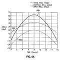
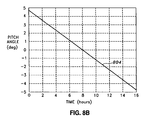
- Figures 6A and 6B depict the total roll offset, the antenna roll offset, the body roll offset, and the body pitch offset for a conventional orbit;
- Figures 7A and 7B depict the total roll offset, the antenna roll offset, the body roll offset, and the body pitch offset for an "
Option 1" orbit; - Figures 8A and 8B depict the total roll offset, the antenna roll offset, the body roll offset, and the body pitch offset for an "
Option 2" orbit; - Figures 9A and 9B depict the total roll offset, the antenna roll offset, the body roll offset, and the body pitch offset for an "
Option 3" orbit; and - Figure 10 is a block diagram of a system that implements the attitude and antenna steering approach according to the present invention.
- The present invention provides an LMSS for North American coverage, which overcomes the deficiencies of conventional MSS systems. Specifically, the present invention provides an enhanced LMSS using an optimized land mobile satellite configuration and steering method, which provides a favorable sun-spacecraft geometry compatible with current and future payload power and thermal requirements, without the need for yaw steering.
- Figure 3 is a diagram depicting the optimized spacecraft configuration according to one embodiment of the present invention. Briefly, the present invention is a method for configuring and operating a spacecraft in an orbit that is inclined with respect to Earth's equatorial plane, the spacecraft including at least a solar array, a receive antenna, a transmit antenna, and radiator panels. The method includes the step of nominally orienting the yaw axis of the spacecraft, the roll axis of the spacecraft, and the radiator panels substantially parallel to Earth's equatorial plane, the pitch axis of the spacecraft and rotation axis of the solar array substantially parallel to Earth's polar axis, the Nadir vector in the yaw-pitch plane of the spacecraft, and the transmit antenna and receive antenna to angle φ nom . The method also includes the step of correcting the attitude of the receive antenna and the transmit antenna to maintain a desired degree of the receive antenna and the transmit antenna steered toward a coverage region on Earth's surface. The correcting step further includes the steps of offsetting the attitude of the spacecraft by angle θ with respect to the pitch axis of the nominal orientation, and by angle φ b with respect to the roll axis of the spacecraft, and offsetting the receive antenna and the transmit antenna at angle φ a with respect to the spacecraft.
- In more detail,
spacecraft 301 includessolar arrays antenna 305, transmitantenna 306, andradiator panels 307. Inherent tospacecraft 301 are yaw axis X b , roll axis Y b , pitch axis Z b , and Nadir vector N (not shown). - Figures 4A and 4B are a flow charts illustrating the method for configuring and operating
spacecraft 301 in an orbit which is inclined with respect to Earth's equatorial plane. As depicted in Figure 4A, the process begins (step S401), and yaw axis X b ofspacecraft 301, roll axis Y b ofspacecraft 301, andradiator panels 307 are nominally oriented substantially parallel to Earth's equatorial plane, and pitch axis Z b ofspacecraft 301 and the rotation axis ofsolar arrays spacecraft 301, and transmitantenna 306 and receiveantenna 307 are oriented to angle φ nom (step S402). - The attitude of receive
antenna 305 and transmitantenna 306 are corrected to maintain a desired degree of receiveantenna 305 and transmitantenna 306 steered toward a coverage region on Earth's surface (step S403), and the process ends (step S408). - As shown in Figure 4B, the correcting step (step S403) begins at sub-step S404, and further includes the sub-steps of offsetting the attitude of
spacecraft 301 by angle θ with respect to the pitch axis of the nominal orientation, and by angle φb with respect to the roll axis of the spacecraft, (sub-step S405), and offsetting receiveantenna 305 and transmitantenna 306 at angle φ a with respect to the spacecraft (sub-step S406). Sub-step S407 ends correcting step S403. - Offset angles are determined based upon maximum allowable sun angle, or roll offset from the nominal orientation. The coverage region is North America, although in alternate aspects of the present invention, the coverage region includes areas outside of North America.
- In contrast to conventional designs, the optimized spacecraft configuration and steering method according to the present invention applies to spacecraft that may operate for extended periods over a wide range of latitudes, such as 16 of 24 hours, and over the entire Northern hemisphere, as required for the SIRIUS SATELLITE RADIO® mobile satellite system. The approach used by the present invention partitions the steering to both the spacecraft and the antenna to provide improved sun geometry for power generation and thermal control. In doing so, the present invention represents a significant improvement over the conventional methods.
- As shown in Figure 3,
spacecraft 301 includes both receiveantenna 305 and transmitantenna 306 that are oriented with their boresights canted at a specified angle φ nom about the body roll (Yb) axis. The antenna design facilitates a roll rotation Δφ scan over a specified range about the nominal roll offset. The nominal angle φ nom is selected based on the orbit parameters, the orbital region of broadcast service, and the coverage region to which service is to be provided. - Figure 5 further illustrates attitude steering according to the present invention, showing the spacecraft in-orbit geometry in a typical highly inclined orbit where LMSS is provided to a coverage region in the Northern hemisphere. As shown in Figure 5, to provide antenna pointing to the coverage region, the antenna boresight tracks a commanded attitude represented by the 3 x 3 transformation matrix expressed below in Equation (1):

- In Equation (1), T φ is the roll correction matrix, T θ is the pitch correction matrix, and T ENP is the Equatorial Nadir Pointing ("ENP") matrix. Antenna pointing is accomplished by a combination of spacecraft body steering and antenna boresight steering, as described more fully below.
- The matrix T ENP describes the nominal spacecraft body pointing direction in inertial space in the absence of additional body pointing corrections, and is expressed below in Equation (2):

- In Equation (2), Z i is the inertial frame earth pole axis vector, and vectors X i and Y i are expressed by Equation (3), below:

- In Equation (3), N is the inertial frame spacecraft Nadir vector. Aligning the body frame with the inertial attitude represented by T ENP causes the spacecraft yaw/roll plane to remain parallel to Earth equatorial plane and the spacecraft pitch axis to remain aligned with Earth pole axis. The Nadir vector remains in the spacecraft yaw/pitch plane, and when the spacecraft crosses the equator, the Nadir vector is aligned with the spacecraft yaw axis. As can be seen from Figure 4, the ENP pointing strategy results in sun angles within ±23.5°, which are compatible with existing GEO spacecraft designs.
- Starting from the ENP attitude, as the spacecraft orbital position changes, antenna pointing is accomplished by commanding the spacecraft body and antenna pointing offsets represented by the matrices of Equation (4):

- In Equation (4), pitch and roll angles θ,φ are as expressed below in Equation (5):

- In Equation (5), V t is a unit vector from the spacecraft to a specified location on Earth's surface in the coverage region, such that the antenna remains correctly pointed. V t , for example, could be the sub-satellite point when the spacecraft is at orbit apogee. The pitch correction is generally implemented as a spacecraft body rotation from the ENP attitude, and does not impact the sun angles from the spacecraft yaw/roll plane. The roll rotation is generally implemented as a combination of body and antenna pointing corrections, as expressed in Equation (6):

- The body and antenna roll corrections φ b and φ a may be determined in any number of ways, depending on the maximum allowable antenna roll scan angle range or the allowable sun angles from the spacecraft yaw/roll plane. One method for partitioning the offsets based on the maximum antenna scan angle Δφ scan is

- In Equation (7), c and φ nom are expressed as shown below in Equation (8):

- In Equations (7) and (8), φ nom is the nominal antenna roll offset in the spacecraft body frame, and Δφ is the roll angle excursion required about the nominal offset, i.e., φ nom - Δφ ≤ φ a ≤ φ nom + Δφ. These quantities are computed based on φmax and φmin, which are the maximum and minimum roll offsets required from the ENP frame over the broadcast service region of the orbit (e.g., the Northern hemisphere).
- Using the pointing strategy outlined above, the maximum spacecraft body roll offset is (1 - c) Δφ , and the maximum sun angle from the spacecraft yaw/roll plane is the sum of this angle and the sun declination of 23.5°. Alternate methods for partitioning the antenna and body roll pointing offsets are also contemplated by the present invention, such as partitioning based on the maximum allowable sun angle or roll offset from the ENP frame.
- Examples of the steering profiles are now given for the orbits given in Table 1, which includes the Sirius Satellite Radio orbit disclosed in U.S. Patent No. 6,564,053 ("the Briskman patent"). Several other optimized orbits which are selected to provide enhanced elevation angles and probability of signal availability for LMSS, denoted as "
Option 1," "Option 2," and "Option 3", are also listed. - The optimized orbits listed in Table 1 have substantially teardrop-shaped or oval-shaped ground tracks, and are optimized based upon performance criteria. A full explanation of the methodology and performance criteria used to select the optimized orbits is available in U.S. Patent Application No. 11/030,282, entitled "Optimized Land Mobile Satellite System For North American Coverage," filed January 7, 2005 ("the Goodzeit '282 application"). Both the Briskman patent and the Goodzeit '282 application are incorporated by reference herein in the entirety for all purposes, although further details relating to the content of both references are omitted for the sake of brevity.
Table 1. Orbits for North American LMSS Parameter SIRIUS Orbit Option 1 Option 2Option 3Inclination 63.4 48.2 45.4 58.9 Eccentricity 0.27 0.24 0.40 0.35 Apogee longitude (° W) 96 95 95 95 Antenna roll offset (°) φ nom 27.5 19.2 25.5 28.7 Roll angle variation about nominal (°) Δφ 35.9 29.0 19.8 30.2 Maximum body roll offset (°) 20.9 14.0 4.8 15.2 Maximum pitch angle (°) 2.2 3.2 4.8 3.0 - All of the orbits listed in Table 1 have a semi-major axis of 42,164 km and an argument of perigee of 270°. Also provided in Table 1 are the nominal antenna roll offset, the roll angle variation about the nominal offset, and the maximum body roll offset, based on Equations (7) and (8). The results of these equations assume an antenna roll scan angle range of ±15°, where the spacecraft operates for ±8 hours about orbit apogee, and where the vector V t in Equation (5) is from the spacecraft to the sub-satellite point at orbit apogee. Table 1 also provides the maximum pitch angle, which is computed using Equation (5).
- Figure 6A is a chart depicting the total roll offset (denoted by reference 601), the antenna roll offset (denoted by reference 602), and the body roll offset (denoted by reference 603) for the orbit described in the Briskman patent, and Figure 6B is a chart depicting the body pitch offset (denoted by reference 604) for the same orbit.
- Figure 7A is a chart depicting the total roll offset (denoted by reference 701), the antenna roll offset (denoted by reference 702), and the body roll offset (denoted by reference 703) for the
Option 1 orbit, and Figure 7B is a chart depicting the body pitch offset (denoted by reference 704) for the same orbit. - Figure 8A is a chart depicting the total roll offset (denoted by reference 801), the antenna roll offset (denoted by reference 802), and the body roll offset (denoted by reference 803) for the
Option 2 orbit, and Figure 8B is a chart depicting the body pitch offset (denoted by reference 804) for the same orbit. - Figure 9A is a chart depicting the total roll offset (denoted by reference 901), the antenna roll offset (denoted by reference 902), and the body roll offset (denoted by reference 903) for the
Option 3 orbit, and Figure 9B is a chart depicting the body pitch offset (denoted by reference 904) for the same orbit. - As can be seen from Table 1 and Figures 6 to 9, the maximum required roll and pitch offsets of 20.9° and 4.8° necessary to implement the steering approach according to the present invention are far smaller than the yaw offsets required to implement a conventional SNP steering approach, which is shown in Figure 2. The reduced spacecraft maneuvering requirements improve attitude pointing performance and allow the use of smaller and lighter reaction wheels assemblies ("RWAs"). Also, it should be noted that the optimized orbits result in a smaller body roll offsets than the conventional orbit, thereby reducing the sun angle from the yaw/roll plane and improving spacecraft power and thermal performance.
- Figure 10 is a block diagram of a system that implements the attitude and antenna steering approach according to the present invention. Inertial
Attitude Determination Logic 1001 computes the spacecraft inertial attitude using gyro angular rate data from Inertial Measurement Unit ("IMU") 1002, and attitude data fromstar trackers 1004 andsun sensors 1005. Those skilled in the art will recognize that other combinations of attitude sensors may be used for attitude determination including earth sensors and other sun sensors. -
Spacecraft Ephemeris Generator 1006 computes the spacecraft orbital position and velocity and provides an estimate of the Nadir vector N , the vector from the spacecraft to Earth's center. Using this vector, the Attitude AndAntenna Steering Logic 1007 computes the commanded spacecraft inertial-to-body frame transformation and commanded antenna roll angle according to the steps described above in Equations (1) to (8). - As described in Equation (6), a portion of the roll pointing command is allocated to the antenna and a portion is allocated to the spacecraft body. In consideration of this partitioning, Equation (1) can also be expressed as Equation (9):

- The spacecraft body portion of the commanded attitude T θ
b T θ T ENP shown in Figure 9, is input to theAttitude Error Logic 1008, which computes the attitude pointing and rate errors representative of the error between the present spacecraft attitude and the commanded inertial attitude. The attitude and rate errors are input to a Proportional-Integral-Derivative ("PID")controller 1009 that computes torque commands for attitude control. The torque commands are then input to RWATorque Distribution Logic 1010 that commandsindividual RWAs 1011 to produce control torque that causes the spacecraft to track the commanded attitude. - The antenna roll pointing correction represented by T φ
a or φ a is input to the AntennaPointing Control Logic 1012. This logic commands theAntenna Pointing Electronics 1013 to achieve the commanded antenna boresight roll pointing. The antenna pointing is controlled either mechanically or electrically, depending on the antenna design. For example, the antenna may include a gimbaled reflector that may be rotated to change the antenna boresight pointing. Alternatively, the antenna may be a phased array antenna design, such that the phases of the individual antenna phase elements are commanded to achieve the desired pointing. - The steering method according to the invention may be augmented with additional spacecraft body and antenna pointing corrections to maximize LMSS signal strength to the overage region as the spacecraft position in orbit changes. Furthermore, the coverage pattern can be enlarged or decreased to compensate for the effects of changes in spacecraft altitude. Additionally, although the steering of antennas has been described above using mechanical steering, other methods, such as electrical steering using a phased array antenna, are also contemplated by the present invention. All of these enhancements are possible without departing from the spirit and scope of the invention.
- The invention has been described with particular illustrative embodiments. It is to be understood that the invention is not limited to the above-described embodiments and that various changes and modifications may be made by those of ordinary skill in the art without departing from the scope of the invention, as defined in the claims.
Claims (17)
- A method for configuring and operating a spacecraft in an orbit that is inclined with respect to Earth's equatorial plane, the spacecraft including at least a solar array, a receive antenna, a transmit antenna, and radiator panels, the method comprising the steps of:nominally orienting the yaw axis of the spacecraft, the roll axis of the spacecraft, and the radiator panels substantially parallel to Earth's equatorial plane, the pitch axis of the spacecraft and rotation axis of the solar array substantially parallel to Earth's polar axis, the Nadir vector in the yaw-pitch plane of the spacecraft, and the transmit antenna and receive antenna to angle φ nom ; andcorrecting the attitude of the receive antenna and the transmit antenna to maintain a desired degree of the receive antenna and the transmit antenna steered toward a coverage region on Earth's surface, further comprising the steps of:offsetting the attitude of the spacecraft by angle θ with respect to the pitch axis of the nominal orientation and by angle φ b with respect to the roll axis of the spacecraft; andoffsetting the receive antenna and the transmit antenna at angle φ a with respect to the spacecraft.
- The method according to Claim 1, wherein angle φ nom is based upon orbit parameters, orbital region of broadcast service, and/or the coverage region.
- The method according to Claim 1, wherein in the correcting step, the receive antenna and the transmit antenna track a commanded attitude expressed by:

wherein T φ is a roll correction matrix, T θ is a pitch correction matrix, and T ENP is expressed by:

wherein T φ and T θ are expressed by:
wherein angles θ and φ are expressed by:
wherein V i is a unit vector from the spacecraft to a location within the coverage region. - The method according to Claim 1, wherein angle φ is expressed by:

wherein φ b and φ a are expressed by:
wherein c and φ nom is expressed by:


wherein Δφ scan is maximum antenna scan angle, φ max is maximum roll offset from the nominal orientation over at least a portion of the orbit, and φ min is minimum roll offset from the nominal orientation over at least a portion of the orbit. - The method according to Claim 1, wherein angle φ b and/or angle φ a are determined based upon maximum allowable sun angle, or roll offset from the nominal orientation.
- The method according to Claim 4, wherein the orbit has a semi-major axis of 42,164 km and an argument of perigee of 270°, and
wherein φ nom is 19.2°, φ scan is 29.0°, φ max is 14.0°, and φ min is 3.2°. - The method according to Claim 4, wherein the orbit has a semi-major axis of 42,164 km and an argument of perigee of 270°, and
wherein φ nom is 25.5°, φ scan is 19.8°, φ max is 4.8°, and φ min is 4.8° - The method according to Claim 4, wherein the orbit has a semi-major axis of 42,164 km and an argument of perigee of 270°, and
wherein φ nom is 28.7°, φ scan is 30.2°, φ max is 15.2°, and φ min is 3.0° - The method according to Claim 1, wherein the coverage region is North America.
- A spacecraft operable in an inclined orbit with respect to Earth's equator, comprising:at least one solar array rotatable about the pitch axis of the spacecraft;a receive antenna;a transmit antenna further comprising an antenna attitude adjuster;at least one radiator panel; anda spacecraft attitude adjustor,wherein the spacecraft is configured such that the spacecraft has a nominal orientation in which the yaw axis of the spacecraft, the roll axis of the spacecraft, and the radiator panels are substantially parallel to Earth's equatorial plane, in which the pitch axis of the spacecraft is substantially parallel to Earth's polar axis, in which the Nadir vector is in the yaw-pitch plane of the spacecraft, and in which the transmit antenna and receive antenna are oriented at angle φ nom , and
wherein the antenna attitude adjustor and the spacecraft attitude adjustor correct the attitude of the transmit antenna to maintain a desired degree of the receive antenna and the transmit antenna steered toward a coverage region on Earth's surface, by offsetting the attitude of spacecraft by angle θ with respect to the pitch axis of the nominal orientation, and by angle φ b with respect to the roll axis of the spacecraft, and by offsetting the receive antenna and the transmit antenna at angle φ a with respect to the spacecraft. - The spacecraft according to Claim 10, wherein angle φ nom is based upon orbit parameters, orbital region of broadcast service, and/or the coverage region.
- The spacecraft according to Claim 10, wherein in the correcting step, the receive antenna and the transmit antenna track a commanded attitude expressed by:

wherein T φ is a roll correction matrix, T θ is a pitch correction matrix, and T ENP is expressed by:
wherein Z i is the Earth's polar axis vector, and vectors X i and Y i are expressed by:
wherein N is a vector from the spacecraft to Earth's center, and
wherein T φ and T θ are expressed by:
wherein angles θ and φ are expressed by:
wherein V i is a unit vector from the spacecraft to a location within the coverage region. - The spacecraft according to Claim 10, wherein angle φ is expressed by:

wherein φ b and φ a are expressed by:
wherein c and φ nom is expressed by:


wherein Δφ scan is maximum antenna scan angle, φ max is maximum roll offset from the nominal orientation over at least a portion of the orbit, and φ min is minimum roll offset from the nominal orientation over at least a portion of the orbit. - The spacecraft according to Claim 10, wherein angle φ b and/or angle φ a are determined based upon maximum allowable sun angle, or roll offset from the nominal orientation.
- The spacecraft according to Claim 13, wherein the orbit has a semi-major axis of 42,164 km and an argument of perigee of 270°, and
wherein φ nom is 19.2°, φ scan is 29.0°, φ max is 14.0°, and φ min is 3.2°. - The spacecraft according to Claim 13, wherein the orbit has a semi-major axis of 42,164 km and an argument of perigee of 270°, and
wherein φ nom is 25.5°, φ scan is 19.8°, φ max is 4.8°, and φ min is 4.8° - The spacecraft according to Claim 13, wherein the orbit has a semi-major axis of 42,164 km and an argument of perigee of 270°, and
wherein φ nom is 28.7°, φ scan is 30.2°, φ max is 15.2°, and φ min is 3.0°
Applications Claiming Priority (2)
| Application Number | Priority Date | Filing Date | Title |
|---|---|---|---|
| US63396204P | 2004-12-07 | 2004-12-07 | |
| US11/048,760 US7624948B2 (en) | 2004-12-07 | 2005-02-03 | Optimized land mobile satellite configuration and steering method |
Publications (1)
| Publication Number | Publication Date |
|---|---|
| EP1669292A1 true EP1669292A1 (en) | 2006-06-14 |
Family
ID=35841902
Family Applications (1)
| Application Number | Title | Priority Date | Filing Date |
|---|---|---|---|
| EP05256912A Withdrawn EP1669292A1 (en) | 2004-12-07 | 2005-11-08 | Optimized land mobile satellite configuration and steering method |
Country Status (2)
| Country | Link |
|---|---|
| US (2) | US7624948B2 (en) |
| EP (1) | EP1669292A1 (en) |
Cited By (1)
| Publication number | Priority date | Publication date | Assignee | Title |
|---|---|---|---|---|
| CN104267735A (en) * | 2014-09-02 | 2015-01-07 | 上海新跃仪表厂 | Inclined orbit satellite yaw maneuvering opportunity judgment method |
Families Citing this family (15)
| Publication number | Priority date | Publication date | Assignee | Title |
|---|---|---|---|---|
| US7357356B1 (en) * | 2005-02-28 | 2008-04-15 | Lockheed Martin Corporation | Attitude and antenna steering system for geosynchronous earth orbit (GEO) spacecraft |
| US7911376B2 (en) * | 2009-04-01 | 2011-03-22 | Sony Corporation | Systems and methods for antenna array calibration |
| US8640994B1 (en) * | 2010-09-27 | 2014-02-04 | The Boeing Company | Agile dedicated spacecraft for spinning microwave imagers and sounders |
| US10587332B2 (en) * | 2014-01-27 | 2020-03-10 | Peter Lemme | System and method for communicating via a satellite in an inclined geosynchronous orbit |
| CN104064869B (en) * | 2014-06-13 | 2016-10-05 | 北京航天万达高科技有限公司 | Biquaternion antenna for satellite communication in motion control method and system based on MEMS inertial navigation |
| CN104181930B (en) * | 2014-09-02 | 2017-02-15 | 上海新跃仪表厂 | Autonomous control method for inclined orbit satellite yaw maneuvering |
| US10135520B2 (en) * | 2015-03-13 | 2018-11-20 | Peter Lemme | System and method for communicating via a satellite in an inclined geosynchronous orbit |
| WO2017008304A1 (en) * | 2015-07-16 | 2017-01-19 | 华为技术有限公司 | Antenna attitude detection method and apparatus |
| CN105253330B (en) * | 2015-10-30 | 2017-04-05 | 中国空间技术研究院 | A kind of information fusion GEO satellite control system menu-type design method based on optimization |
| AU2017260347B2 (en) * | 2016-05-03 | 2021-10-21 | Theia Group, Incorporated | Low earth orbit satellite constellation system for communications with re-use of geostationary satellite spectrum |
| KR101898641B1 (en) * | 2017-08-16 | 2018-10-31 | 한국항공우주연구원 | Satellite and method for controlling the same |
| US10841389B2 (en) * | 2018-02-13 | 2020-11-17 | Oracle International Corporation | Increasing reliability of push notification-based authentication or authorization |
| CN112389681B (en) * | 2018-04-08 | 2022-05-17 | 上海微小卫星工程中心 | A magnetron method for satellite orientation to the sun |
| CN112278325B (en) * | 2020-09-21 | 2022-05-24 | 北京控制工程研究所 | A Total Angle of Attack Control Method Based on Normal Overload |
| CN115180178A (en) * | 2022-07-26 | 2022-10-14 | 北京航空航天大学 | Solar sail based on distributed configuration |
Citations (2)
| Publication number | Priority date | Publication date | Assignee | Title |
|---|---|---|---|---|
| EP1116657A2 (en) * | 2000-01-10 | 2001-07-18 | Space Systems / Loral, Inc. | Equatorial-normal body-stabilized spacecraft and control method for inclined orbit operation |
| US6616104B1 (en) | 2002-06-24 | 2003-09-09 | Lockheed Martin Corporation | Spacecraft configuration and attitude steering method for highly inclined orbit (HIO) communications |
Family Cites Families (14)
| Publication number | Priority date | Publication date | Assignee | Title |
|---|---|---|---|---|
| US6223019B1 (en) * | 1996-03-14 | 2001-04-24 | Sirius Satellite Radio Inc. | Efficient high latitude service area satellite mobile broadcasting systems |
| GB2320232B (en) * | 1996-12-12 | 2000-09-27 | Ico Services Ltd | Satellite and Method of Operating a Satellite |
| US6695259B1 (en) | 1997-05-21 | 2004-02-24 | Hitachi, Ltd. | Communication system, communication receiving device and communication terminal in the system |
| US6019318A (en) | 1997-06-16 | 2000-02-01 | Hugehs Electronics Corporation | Coordinatable system of inclined geosynchronous satellite orbits |
| US20030189136A1 (en) | 1998-05-20 | 2003-10-09 | Toshihide Maeda | Communication system, communication receiving device and communication terminal in the system |
| US6283415B1 (en) * | 1999-04-29 | 2001-09-04 | Hughes Electronics Corporation | Simplified yaw steering method for satellite antenna beam control |
| US6442385B1 (en) | 1999-11-04 | 2002-08-27 | Xm Satellite Radio, Inc. | Method and apparatus for selectively operating satellites in tundra orbits to reduce receiver buffering requirements for time diversity signals |
| US6511020B2 (en) * | 2000-01-07 | 2003-01-28 | The Boeing Company | Method for limiting interference between satellite communications systems |
| US7369809B1 (en) | 2000-10-30 | 2008-05-06 | The Directv Group, Inc. | System and method for continuous broadcast service from non-geostationary orbits |
| US6714521B2 (en) | 2000-12-29 | 2004-03-30 | Space Resources International Ltd. | System and method for implementing a constellation of non-geostationary satellites that provides simplified satellite tracking |
| EP1512233A2 (en) | 2001-12-21 | 2005-03-09 | Global Radio S.A. | A highly elliptical orbit for communications satellites |
| WO2003065595A2 (en) | 2002-01-29 | 2003-08-07 | Virtual Geosatellite, L.L.C. | Virtually geostationary satellite array with optimized parameters |
| US6851651B2 (en) | 2002-02-15 | 2005-02-08 | Lockheed Martin Corporation | Constellation of spacecraft, and broadcasting method using said constellation |
| US7357356B1 (en) * | 2005-02-28 | 2008-04-15 | Lockheed Martin Corporation | Attitude and antenna steering system for geosynchronous earth orbit (GEO) spacecraft |
-
2005
- 2005-02-03 US US11/048,760 patent/US7624948B2/en not_active Expired - Fee Related
- 2005-11-08 EP EP05256912A patent/EP1669292A1/en not_active Withdrawn
-
2009
- 2009-09-14 US US12/559,246 patent/US7832688B2/en not_active Expired - Fee Related
Patent Citations (2)
| Publication number | Priority date | Publication date | Assignee | Title |
|---|---|---|---|---|
| EP1116657A2 (en) * | 2000-01-10 | 2001-07-18 | Space Systems / Loral, Inc. | Equatorial-normal body-stabilized spacecraft and control method for inclined orbit operation |
| US6616104B1 (en) | 2002-06-24 | 2003-09-09 | Lockheed Martin Corporation | Spacecraft configuration and attitude steering method for highly inclined orbit (HIO) communications |
Non-Patent Citations (1)
| Title |
|---|
| R. BRISKMAN: "S-DARS Broadcast For Inclined elliptical Orbits", 52ND INTERNATIONAL ASTRONAUTICAL CONGRESS |
Cited By (2)
| Publication number | Priority date | Publication date | Assignee | Title |
|---|---|---|---|---|
| CN104267735A (en) * | 2014-09-02 | 2015-01-07 | 上海新跃仪表厂 | Inclined orbit satellite yaw maneuvering opportunity judgment method |
| CN104267735B (en) * | 2014-09-02 | 2017-06-06 | 上海新跃仪表厂 | A kind of inclined plane satellite yawing maneuvering opportunity determination methods |
Also Published As
| Publication number | Publication date |
|---|---|
| US7624948B2 (en) | 2009-12-01 |
| US7832688B2 (en) | 2010-11-16 |
| US20100001142A1 (en) | 2010-01-07 |
| US20060118677A1 (en) | 2006-06-08 |
Similar Documents
| Publication | Publication Date | Title |
|---|---|---|
| US7832688B2 (en) | Optimized land mobile satellite configuration and steering | |
| US6637701B1 (en) | Gimbaled ion thruster arrangement for high efficiency stationkeeping | |
| EP0648027B1 (en) | Medium-earth-altitude satellite based cellular telecommunications | |
| US11101553B2 (en) | Antenna system with active array on tracking pedestal | |
| US8511617B2 (en) | Satellites and satellite fleet implementation methods and apparatus | |
| JP6391650B2 (en) | Satellite system and method for polar latitudes | |
| US9045239B2 (en) | Spacecraft payload orientation steering | |
| US8123173B1 (en) | Attitude and antenna steering system and method for spacecraft | |
| US6616104B1 (en) | Spacecraft configuration and attitude steering method for highly inclined orbit (HIO) communications | |
| JP2003507951A (en) | General-purpose replacement communication satellite | |
| US12431623B2 (en) | Antenna module grounding for phased array antennas | |
| US6288670B1 (en) | Combined roll-yaw spacecraft steering method for low earth orbit target trajectory compensation | |
| EP3381812B1 (en) | A low earth orbiting spacecraft | |
| US20130062471A1 (en) | Inclined orbit satellite communication system | |
| CA3006500C (en) | Satellite system and method for global coverage | |
| Briskman et al. | S-DARS broadcast from inclined, elliptical orbits | |
| US6570528B1 (en) | Antenna system for multiple orbits and multiple areas | |
| EP1116657A2 (en) | Equatorial-normal body-stabilized spacecraft and control method for inclined orbit operation | |
| Briskman et al. | DARS satellite constellation performance | |
| US12463716B1 (en) | Low earth orbit satellite constellation system | |
| Rao et al. | Reconfigurable antenna system for satellite communications | |
| US20230369737A1 (en) | Antenna reflector spacecraft temperature regulation during orbit raising | |
| Ichikawa | The results of initial checkup of Japanese broadcasting satellite for experimental purpose | |
| JP2001063700A (en) | Orbit control method of artificial satellite, control method of beam irradiation area, and artificial satellite system | |
| JP2000115050A (en) | Satellite communication system |
Legal Events
| Date | Code | Title | Description |
|---|---|---|---|
| PUAI | Public reference made under article 153(3) epc to a published international application that has entered the european phase |
Free format text: ORIGINAL CODE: 0009012 |
|
| AK | Designated contracting states |
Kind code of ref document: A1 Designated state(s): AT BE BG CH CY CZ DE DK EE ES FI FR GB GR HU IE IS IT LI LT LU LV MC NL PL PT RO SE SI SK TR |
|
| AX | Request for extension of the european patent |
Extension state: AL BA HR MK YU |
|
| 17P | Request for examination filed |
Effective date: 20060920 |
|
| AKX | Designation fees paid |
Designated state(s): FR |
|
| REG | Reference to a national code |
Ref country code: DE Ref legal event code: 8566 |
|
| GRAP | Despatch of communication of intention to grant a patent |
Free format text: ORIGINAL CODE: EPIDOSNIGR1 |
|
| STAA | Information on the status of an ep patent application or granted ep patent |
Free format text: STATUS: THE APPLICATION IS DEEMED TO BE WITHDRAWN |
|
| 18D | Application deemed to be withdrawn |
Effective date: 20071019 |